EP1010967B1 - Kodierer zur Lieferung von inkrementalen und absoluten Positionswerten - Google Patents
Kodierer zur Lieferung von inkrementalen und absoluten Positionswerten Download PDFInfo
- Publication number
- EP1010967B1 EP1010967B1 EP99121038A EP99121038A EP1010967B1 EP 1010967 B1 EP1010967 B1 EP 1010967B1 EP 99121038 A EP99121038 A EP 99121038A EP 99121038 A EP99121038 A EP 99121038A EP 1010967 B1 EP1010967 B1 EP 1010967B1
- Authority
- EP
- European Patent Office
- Prior art keywords
- photodetectors
- optical encoder
- detecting unit
- incremental
- code
- Prior art date
- Legal status (The legal status is an assumption and is not a legal conclusion. Google has not performed a legal analysis and makes no representation as to the accuracy of the status listed.)
- Expired - Lifetime
Links
- 230000003287 optical effect Effects 0.000 claims abstract description 29
- 230000010363 phase shift Effects 0.000 description 5
- 238000000034 method Methods 0.000 description 2
- VYZAMTAEIAYCRO-UHFFFAOYSA-N Chromium Chemical compound [Cr] VYZAMTAEIAYCRO-UHFFFAOYSA-N 0.000 description 1
- 230000005534 acoustic noise Effects 0.000 description 1
- 229910052804 chromium Inorganic materials 0.000 description 1
- 239000011651 chromium Substances 0.000 description 1
- 238000010276 construction Methods 0.000 description 1
- 238000011109 contamination Methods 0.000 description 1
- 230000001419 dependent effect Effects 0.000 description 1
- 238000011156 evaluation Methods 0.000 description 1
- 239000011521 glass Substances 0.000 description 1
- 238000012986 modification Methods 0.000 description 1
- 230000004048 modification Effects 0.000 description 1
- 239000000758 substrate Substances 0.000 description 1
- 230000001131 transforming effect Effects 0.000 description 1
- 238000004804 winding Methods 0.000 description 1
Images
Classifications
-
- G—PHYSICS
- G01—MEASURING; TESTING
- G01D—MEASURING NOT SPECIALLY ADAPTED FOR A SPECIFIC VARIABLE; ARRANGEMENTS FOR MEASURING TWO OR MORE VARIABLES NOT COVERED IN A SINGLE OTHER SUBCLASS; TARIFF METERING APPARATUS; MEASURING OR TESTING NOT OTHERWISE PROVIDED FOR
- G01D5/00—Mechanical means for transferring the output of a sensing member; Means for converting the output of a sensing member to another variable where the form or nature of the sensing member does not constrain the means for converting; Transducers not specially adapted for a specific variable
- G01D5/26—Mechanical means for transferring the output of a sensing member; Means for converting the output of a sensing member to another variable where the form or nature of the sensing member does not constrain the means for converting; Transducers not specially adapted for a specific variable characterised by optical transfer means, i.e. using infrared, visible, or ultraviolet light
- G01D5/32—Mechanical means for transferring the output of a sensing member; Means for converting the output of a sensing member to another variable where the form or nature of the sensing member does not constrain the means for converting; Transducers not specially adapted for a specific variable characterised by optical transfer means, i.e. using infrared, visible, or ultraviolet light with attenuation or whole or partial obturation of beams of light
- G01D5/34—Mechanical means for transferring the output of a sensing member; Means for converting the output of a sensing member to another variable where the form or nature of the sensing member does not constrain the means for converting; Transducers not specially adapted for a specific variable characterised by optical transfer means, i.e. using infrared, visible, or ultraviolet light with attenuation or whole or partial obturation of beams of light the beams of light being detected by photocells
- G01D5/347—Mechanical means for transferring the output of a sensing member; Means for converting the output of a sensing member to another variable where the form or nature of the sensing member does not constrain the means for converting; Transducers not specially adapted for a specific variable characterised by optical transfer means, i.e. using infrared, visible, or ultraviolet light with attenuation or whole or partial obturation of beams of light the beams of light being detected by photocells using displacement encoding scales
- G01D5/34776—Absolute encoders with analogue or digital scales
- G01D5/34792—Absolute encoders with analogue or digital scales with only digital scales or both digital and incremental scales
Definitions
- This invention relates to position sensors or encoders which produce electrical signals indicative of the position of a moving object.
- the invention relates to an encoder that provides incremental position data as well as coarse absolute position data.
- rotary encoders which provide incremental output signals as well as coarse absolute output signals, e.g. commutation output signals.
- Commutation output signals are necessary in brushless motors where commutation is performed by electronically steering drive current in the motor to the appropriate winding.
- the absolute rotor position has to be determined with a certain accuracy.
- Hall switches are used to determine the absolute rotor position. The Hall devices are arranged on a circuit board, which is aligned with a magnet on the rotor so that a defined relationship between the Hall outputs and the motor back EMF can be established.
- each of the code tracks is scanned by a further photodetector which provides either a HIGH output or a LOW output.
- the combination of the three commutation output signals allows determination of the absolute rotor position within a certain range.
- An optical encoder is able to provide absolute and incremental positional information of an object which moves along a certain measuring direction.
- the encoder has a single data track positioned along the measuring direction, having a fine incremental track and a plurality of separate coarse code tracks overlying said incremental track.
- a light source is provided for emitting light in the direction of the data track.
- a first detecting unit is arranged with respect to the data track for receiving light modulated by said incremental graduation.
- the first detecting unit consists of an array of separate photodetectors, each of the photodetectors providing phase shifted incremental signals.
- a second detecting unit is arranged with respect to the data track for receiving light modulated by said at least three separate coarse code tracks.
- the second detecting unit has a number of separate photodetectors and the number of photodetectors is equal to the number of coarse code tracks.
- An optical rotary encoder is able to provide incremental output signals and commutation output signals suitable for controlling a brushless motor.
- the encoder has a single circular data track arranged on a code wheel, having a fine incremental track with a defined incremental graduation period and three separate concentrically arranged coarse code tracks overlying said incremental graduation.
- a light source is provided for emitting light in the direction of the data track.
- a first detecting unit is arranged with respect to the data track for receiving light modulated by said incremental track.
- the first detecting unit consists of an array of separate photodetectors, each of the photodetectors providing phase shifted incremental output signals. Those photodetectors of the first detecting unit are connected electrically with each other, which provides output signals with the same phase relationship.
- a second detecting unit is arranged with respect to the data track for receiving light modulated by said plurality of code tracks.
- the second detecting unit has three separate photodetectors. The combination of the output signals of the photodetectors of the second detecting unit provides absolute position information within a certain angular range.
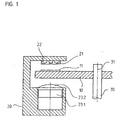
- Figure 1 illustrates schematically a cross section of an optical encoder according to a preferred embodiment of the present invention.
- the optical encoder is a rotary encoder and as described below is able to generate positional information with respect to the movement of two rotating objects.
- the encoder can be used, for example, in applications together with brushless motors.
- the optical encoder of this preferred embodiment includes a code wheel 10 with a single data track 11, the code wheel 10 being mounted on a shaft 30 which rotates around axis 31.
- the rotating shaft 30 can be the rotor of a brushless DC motor for example.
- the encoder has a scanning unit 20 for photoelectrically scanning the data track 11.
- the scanning unit 20 comprises two detecting units 21, 22, a light source 23.1 and a lens 23.2, preferably a condenser lens.
- the data track 11 of the rotating code wheel 10 is arranged between light source 23.1 and condenser lens 23.2 on one side and the detecting units 21, 22 on the other side.
- the emitted light of the light source 23.1 is collimated by condenser lens 23.2 and transmitted through data track 11 on the code wheel 10.
- the detecting units 21, 22 receive the light which is modulated by the data track 11 if the code wheel 10 rotates.
- the detected signals are processed in an evaluation unit which is not shown in FIG. 1.
- the encoder structure is illustrated only schematically because details of mechanical construction are well known to those of ordinary skill in the art. It should be mentioned furthermore that the present invention is not limited to rotary encoders. It is also applicable in linear encoders with linearly arranged data tracks. Additionally it should be mentioned that different optical principles can be realized on the basis of the present invention, such as transmitted light arrangements as described in FIGS. 1 - 5 as well as reflected light arrangements. Details of the inventive data track and the inventive detector unit arrangement will be described now with reference to FIG. 2, 5 and the following FIGS. 3, 4 which show details of FIG. 2 in enlarged views. FIG.
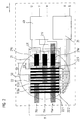
- FIG. 2 is a schematic illustration of a view onto the detector units 21, 22 and the single data track 11 which is photoelectrically scanned by the detector units 21, 22 when the code wheel rotates. Furthermore a part of the signal processing electronics 35, 40 is schematically illustrated in FIG. 2.
- the circle 50 in FIG. 2 should indicate the area on the single data track 11 on the code wheel which is illuminated by the light source and which is scanned by the detector units 21, 22 to generate position dependent output signals.
- the single data track 11 of the inventive rotary encoder is arranged along the measuring direction of the encoder. In the present case of a rotary encoder the measuring direction is defined by the circumferential arrangement of the data track on the code wheel.
- the measuring direction is given by the linear direction of motion of the scanning unit with respect to a linear scale.
- the measuring direction is defined by the direction of movement of the data track and the scanning unit.
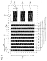
- the data track 11 according to the present invention has a first graduation which is embodied as fine incremental track with a defined incremental graduation period TP. Accordingly this track serves to generate incremental output signals which are indicative of the relative position of two objects which are moving with respect to each other.
- the incremental track consists of opaque and clear areas 11.lo, 11.lc which are alternately arranged in the measuring direction on the code wheel.
- the incremental track consists of opaque chromium lines arranged on a transparent glass substrate.
- Opaque and clear areas 11.lo, 11.lc both have the same width DX in the measuring direction and the same length LR perpendicular to the measuring direction.
- the single data track of the inventive encoder has additional coarse graduations which are embodied as coarse code tracks 11.U, 11.V, 11.W and which are overlying the fine incremental track.
- the opaque and clear areas 11.lo, 11.lc of the incremental track have a length in radial direction which is bigger than the width of the three parallel arranged code tracks in radial direction.
- the code tracks 11.U, 11.V, 11.W are used to generate coarse absolute position information with respect to the rotary movement of the code wheel.
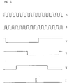
- FIGS. 2 - 4 there are three coarse code tracks 11.U, 11.V, 11.W shown which are especially suitable to generate commutation signals U, V, W (FIG. 5) having a certain phase shift with respect to each other.
- a coarse absolute position value can be determined in a suitable processing electronics in a matter which is known to those of ordinary skill in the art.
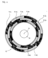
- Each of the coarse code tracks 11.U, 11.V, 11.W has alternately arranged clear and opaque areas 11.Uc, 11.Uo, 11.Vc, 11.Vo, 11.Wc, 11 .Wo. These areas all have the shape of arc segments which is shown in FIG. 4. The segment angle of all these areas is chosen identically in the described embodiment.
- the three code tracks 11.U, 11.V, 11 .W are arranged circumferentially around the rotational axis 31 with a relationship to each other so that a coarse absolute position within a certain angular range can be determined.
- the output signals of the three detectors which are used to scan the coarse code tracks are combined logically in a well known manner.
- four opaque areas 11 .Uo. 11.Vo, 11 .Wo and four clear areas 11.Uc, 11 .Vc, 11 .We are arranged alternately in each code track 11U, 11.V, 11.W.
- Each of these code areas 11.Uc, 11.Uo, 11.Vc, 11 .Vo, 11 .We, 11.Wo covers an arc segment of 45°.
- the code areas 11.Uc, 11.Uo, 11.Vc, 11.Vo, 11 .We, 11.Wo of adjacent code tracks are shifted with respect to each other by 30°.
- This configuration provides a resolution of 15° with each 90° segment, and is suitable for commutation of an 8-pole brushless motor.
- This pattern can be modified to repeat every 120° or every 180° for commutation of 6- or 4-pole motors, respectively.
- the inventive encoder integrates an incremental track and a plurality of separate code tracks within one single data track. Accordingly both tracks exist in the same space so that it becomes possible to build a very compact optical encoder. It is only necessary to illuminate a relatively small area on the code wheel, which allows a smaller optic assembly to be incorporated in the inventive encoder. Now the arrangement of the detecting units should be described which are provided in the inventive encoder to scan the single data track 11 on code wheel 10.
- a first detecting unit 22 is used to scan the incremental track of data track 1 and to provide incremental output signals A, B which are phase shifted by 90°.
- the first detecting unit 22 comprises an array of separate photodetectors 22.1 - 22.9. In FIG. 2 only a part of all the photodetectors is shown for reasons of clarity.
- the first detecting unit 22 has e.g. 100 separate photodetectors. All photodetectors of the first detecting unit 22 have a rectangular shaped light sensitive area.
- the longitudinal axis of the rectangular shaped photodetectors is oriented perpendicular to the measuring direction.
- the photodetectors 22.1 - 22.9 have a length l INC and a width w INC whereas adjacent photodetectors 22.1 - 22.9 are arranged in a distance d INC with respect to each other.
- these parameters of the first detecting unit are chosen as follows:
- this arrangement provides signals from adjacent photodetectors which are phase shifted with respect to each other by 90°.
- the photodetectors are arranged in groups of four so that one group of photodetectors generates incremental output signals a, b, a*, b*.
- These signals a, b, a*, b* are derived from one grating period TP of the incremental track on the code wheel so that a so called “one-field-scanning" arrangement results. It offers significant advantages with respect to the influence of possible contaminations on the code wheel.
- signal b has a phase shift of 90°, signal a' a phase shift of 180° and signal b* a phase shift of 270° with respect to the phase of signal a which is generated by the first photodetector of each group.
- Those photodetectors of all groups are connected, electrically with each other which provide incremental output signals with the same phase relationship. So, for example, photodector 22.1 of the first group and photodetector 22.5 of the second group are connected with each other etc..
- the resulting four incremental output signals a, b, a*, b* are further processed in conventional manner in a push-pull circuit within a subsequent processing unit 35.
- the output signals A, B of the processing unit 35 are incremental signals with balanced amplitudes which are phase shifted with respect to each other by 90°. If the resulting resolution of the graduation period is not high enough it is possible to interpolate these signals.
- the incremental signals A, B generated by the processing unit may be TTL square wave signals or sine shaped signals.
- the suggested arrangement of the first detecting unit for scanning the incremental track offers certain advantages if the graduation is contaminated locally. In this case all signals are influenced in the same way so that very stable incremental scanning signals result even in this case. It can be seen in FIG. 2 that the length LR of the incremental graduation is chosen bigger than the length l INC of the photodetectors of the first detecting unit 22.
- the second detecting unit 21 Adjacent to the first detecting unit 22 there is a second detecting unit 21 arranged in the scanning unit to scan the coarse code tracks of the single data track on the code wheel.
- the photodetectors 21 U, 21 V, 21 W of the second detecting unit are arranged parallel to each other whereas their longitudinal axis coincide with the measuring direction or are parallel oriented therewith. By this arrangement it is possible to scan the coarse code tracks which are integrated together with the fine incremental track within a single data track.
- Each of the photodetectors 21 U, 21V, 21W provides an analog output signal which is either in a HIGH state or in a LOW state depending on the area of the code track which is actually scanned. So scanning of a clear code area provides an analog HIGH signal whereas scanning of an opaque area provides an analog LOW signal.
- a subsequent processing unit 40 which comprises especially a number of comparators to transform the analog output signals of photodetectors 21 U, 21 V, 21W into digital output signals U, V, W having two possible logical states 1 or 0.
- a subsequent processing unit 40 which comprises especially a number of comparators to transform the analog output signals of photodetectors 21 U, 21 V, 21W into digital output signals U, V, W having two possible logical states 1 or 0.
- a subsequent processing unit 40 which comprises especially a number of comparators to transform the analog output signals of photodetectors 21 U, 21 V, 21W into digital output signals U, V, W having two possible logical states 1 or 0.
- the inventive arrangement of the detecting units as described above ensures: a) that the incremental output signals A, B are not disturbed by the code track structure in the data track; and b) that the incremental track structure does not impact the generation of the absolute output signals U, V, W.
- the output signals A, B as well as U, V, W generated with the inventive encoder of FIGS. 1 ⁇ 4 are shown in FIG. 5.
- a further reference signal Z is shown in Fig. 5 which can be generated in well known manner.
- These signals can be processed in a suitable control of a brushless motor, for example.
- n photodetectors are arranged within one group which has an extension of TP in the measuring direction so that n incremental output signals result having a phase relationship of 360°/n with respect to each other.
- the number of groups of photodetectors in the first detecting unit can be varied in accordance with the available space in the scanning unit.
Claims (17)
- Optische Positionsmesseinrichtung zur Erzeugung absoluter und inkrementeller Positionsinformationen bzgl. eines Objekts, das sich entlang einer bestimmten Meßrichtung bewegt, wobei die Positionsmesseinrichtung Folgendes umfaßt:eine einzelne Datenspur (11), die entlang der Meßrichtung angeordnet ist und eine feine Inkrementalspur mit einer definierten inkrementellen Teilungsperiode undmehrere gesonderte grobe Codespuren aufweist, die der Inkrementalspur überlagert ist;eine Lichtquelle (23.1), um Licht in die Richtung der Datenspur auszustrahlen;eine erste Detektoreinheit (22), die in Bezug auf die Datenspur angeordnet ist, um Licht, das durch die Inkrementalspur moduliert wurde, zu empfangen;wobei die erste Detektoreinheit aus einer Anordnung von gesonderten Photodetektoren (22.1 bis 22.9) besteht, und jeder der Photodetektoren phasenverschobene inkrementelle Ausgangssignale (A, B) bereitstellt;eine zweite Detektoreinheit (21), die in Bezug auf die Datenspur angeordnet ist, um Licht, das durch die mehreren Codespuren moduliert wurde, zu empfangen;wobei die zweite Detektoreinheit eine Anzahl von gesonderten Photodetektoren (21U, 21V, 21W) aufweist, und die Anzahl der Photodetektoren gleich der Anzahl der Codespuren ist;wobei die Kombination der Ausgangssignale der Photodetektoren der zweiten Detektoreinheit absolute Positionsinformationen bereitstellt.
- Optische Positionsmesseinrichtung nach Anspruch 1, wobei die Datenspur drei gesonderte grobe Codespuren (11.U, 11.V, 11.W) aufweist.
- Optische Positionsmesseinrichtung nach Anspruch 1, wobei die Datenspur umfänglich auf einer Codescheibe (10) angeordnet ist.
- Optische Positionsmesseinrichtung nach Anspruch 3, wobei die Codescheibe an einer Welle (30) angebracht ist.
- Optische Positionsmesseinrichtung nach Anspruch 4, wobei die feine Inkrementalteilung abwechselnd angeordnete durchsichtige Bereiche (11.Ic) und undurchsichtige Bereiche (11.Io) aufweist, die alle eine gleiche Breite (DX) und eine gleiche Länge (LR) aufweisen.
- Optische Positionsmesseinrichtung nach Anspruch 3, wobei jede der drei groben Codespuren vier durchsichtige Bereiche (11.Uc, 11.Vc, 11.Wc) und vier undurchsichtige Bereiche (11.Uo, 11.Vo, 11.Wo) aufweist, die abwechselnd um den Umfang der Codescheibe angeordnet sind.
- Optische Positionsmesseinrichtung nach Anspruch 6, wobei die drei Codespuren in Bezug zueinander um einen vorbestimmten Winkel verschoben sind, so daß aus den Ausgangssignalen der zweiten Detektoreinheit eine bestimmte Anzahl von Umfangsbereichen absolut bestimmt werden kann.
- Optische Positionsmesseinrichtung nach Anspruch 1, wobei die Inkrementalteilung aus abwechselnd angeordneten rechteckigen Bereichen mit unterschiedlichen optischen Eigenschaften besteht.
- Optische Positionsmesseinrichtung nach Anspruch 8, wobei die rechteckigen Bereiche jeweils eine Längsachse aufweisen, die in Bezug auf die Meßrichtung senkrecht verläuft.
- Optische Positionsmesseinrichtung nach Anspruch 2, wobei die zumindest drei gesonderten groben Codespuren jeweils aus abwechselnd angeordneten Codebereichen mit unterschiedlichen optischen Eigenschaften bestehen.
- Optische Positionsmesseinrichtung nach Anspruch 10, wobei die Codebereiche jeweils eine Längsachse aufweisen, die parallel zur Meßrichtung verläuft.
- Optische Positionsmesseinrichtung nach Anspruch 1, wobei die Photodetektoren der ersten Detektoreinheit eine rechteckige Form aufweisen.
- Optische Positionsmesseinrichtung nach Anspruch 12, wobei die Photodetektoren jeweils eine Längsachse aufweisen, die senkrecht zur Meßrichtung angeordnet ist.
- Optische Positionsmesseinrichtung nach Anspruch 12, wobei benachbarte Photodetektoren der ersten Detektoreinheit in Bezug zueinander angeordnet sind, so daß sich von benachbarten Photodetektoren inkrementelle Ausgangssignale ergeben, die um 90 ° phasenverschoben sind.
- Optische Positionsmesseinrichtung nach Anspruch 12, wobei die Photodetektoren der zweiten Detektoreinheit eine rechteckige Form aufweisen und neben den Photodetektoren der ersten Detektoreinheit angeordnet sind.
- Optische Positionsmesseinrichtung nach Anspruch 15, wobei die Photodetektoren der zweiten Detektoreinheit jeweils eine Längsachse aufweisen, die senkrecht zur Längsachse der Photodetektoren der ersten Detektoreinheit angeordnet ist.
- Optische Positionsmesseinrichtung nach Anspruch 14, wobei jeder vierte Photodetektor verbunden ist.
Applications Claiming Priority (2)
| Application Number | Priority Date | Filing Date | Title |
|---|---|---|---|
| US212782 | 1980-12-04 | ||
| US09/212,782 US6175109B1 (en) | 1998-12-16 | 1998-12-16 | Encoder for providing incremental and absolute position data |
Publications (3)
| Publication Number | Publication Date |
|---|---|
| EP1010967A2 EP1010967A2 (de) | 2000-06-21 |
| EP1010967A3 EP1010967A3 (de) | 2001-06-06 |
| EP1010967B1 true EP1010967B1 (de) | 2006-03-15 |
Family
ID=22792404
Family Applications (1)
| Application Number | Title | Priority Date | Filing Date |
|---|---|---|---|
| EP99121038A Expired - Lifetime EP1010967B1 (de) | 1998-12-16 | 1999-10-21 | Kodierer zur Lieferung von inkrementalen und absoluten Positionswerten |
Country Status (5)
| Country | Link |
|---|---|
| US (1) | US6175109B1 (de) |
| EP (1) | EP1010967B1 (de) |
| JP (1) | JP2000180213A (de) |
| AT (1) | ATE320589T1 (de) |
| DE (1) | DE69930341T2 (de) |
Families Citing this family (23)
| Publication number | Priority date | Publication date | Assignee | Title |
|---|---|---|---|---|
| DE19944005A1 (de) * | 1999-09-14 | 2001-03-15 | Kostal Leopold Gmbh & Co Kg | Optoelektronischer Drehwinkelsensor |
| GB9926574D0 (en) | 1999-11-11 | 2000-01-12 | Renishaw Plc | Absolute position measurement |
| DE10100619C2 (de) * | 2001-01-09 | 2003-05-08 | Siemens Production Und Logisti | Einrichtung zu Positionierung einer Bauelementeaufnahmeeinheit eines Bestückautomaten für Leiterplatten |
| WO2002027270A1 (de) † | 2000-09-28 | 2002-04-04 | Carl Zeiss | Koordinatenmessgerät |
| GB0103582D0 (en) | 2001-02-14 | 2001-03-28 | Renishaw Plc | Position determination system |
| US6660996B1 (en) | 2001-07-03 | 2003-12-09 | Lexmark International, Inc. | System and method for examining relationship between intersecting encoder output signals |
| FR2830139B1 (fr) * | 2001-09-26 | 2004-08-27 | Roulements Soc Nouvelle | Dispositif a commutation electronique commande par impulsions |
| US6727493B2 (en) | 2001-11-06 | 2004-04-27 | Renco Incoders, Inc. | Multiple resolution photodiode sensor array for an optical encoder |
| US6963064B2 (en) * | 2002-06-14 | 2005-11-08 | Pem Management, Inc. | Multi-resolution reflective optical incremental encoder |
| US6731032B1 (en) * | 2002-10-09 | 2004-05-04 | Dana Corporation | Electric motor with magnetic sensor wheel |
| DE10256333A1 (de) * | 2002-12-03 | 2004-06-17 | Leopold Kostal Gmbh & Co Kg | Optoelektronische Messeinrichtung zum Erfassen einer Relativbewegung zwischen einem Geber und einer Sensorzeile sowie optoelektronische Sensorzeile |
| DE10309679B4 (de) * | 2003-02-27 | 2014-05-22 | Dr. Johannes Heidenhain Gmbh | Abtasteinheit zum Abtasten einer Maßverkörperung |
| JP2005017116A (ja) * | 2003-06-26 | 2005-01-20 | Sharp Corp | 光学式エンコーダ用受光素子 |
| EP2072133A1 (de) * | 2007-12-20 | 2009-06-24 | Koninklijke Philips Electronics N.V. | Mehrkammervorrichtung mit magnetischen Partikeln |
| US8309906B2 (en) | 2010-06-10 | 2012-11-13 | Mitutoyo Corporation | Absolute optical encoder with long range intensity modulation on scale |
| US8525459B2 (en) * | 2010-07-15 | 2013-09-03 | Heidenhain Corporation | Code disk, optical encoder, and motor system |
| DE102012212767A1 (de) * | 2012-07-20 | 2014-01-23 | Dr. Johannes Heidenhain Gmbh | Positionsmesseinrichtung |
| EP3148499A4 (de) * | 2014-05-29 | 2018-02-21 | Resuscitation International, LLC | Elektromechanisches thoraxkompressionssystem und -verfahren |
| US9933284B2 (en) * | 2015-08-26 | 2018-04-03 | Novanta Corporation | Multi-track absolute encoder |
| DE102016122862A1 (de) | 2016-11-28 | 2018-05-30 | Wobben Properties Gmbh | Messsystem und ein Messverfahren zum Vermessen eines Stators einer getriebelosen Windenergieanlage |
| TWI646311B (zh) * | 2018-01-02 | 2019-01-01 | 大銀微系統股份有限公司 | 光學編碼感測裝置 |
| DE102020134604B4 (de) | 2020-12-22 | 2022-07-14 | Smaract Gmbh | Vorrichtung und Verfahren zur Positionsbestimmung |
| CN113028962B (zh) * | 2021-03-09 | 2023-06-02 | 浙江禾川科技股份有限公司 | 一种编码器 |
Family Cites Families (17)
| Publication number | Priority date | Publication date | Assignee | Title |
|---|---|---|---|---|
| GB1143542A (de) * | 1965-11-16 | |||
| FR2310549A1 (fr) * | 1975-05-07 | 1976-12-03 | Sagem | Perfectionnements aux dispositifs optiques de determination de la position d'un organe mobile |
| DE3010611C2 (de) | 1980-03-20 | 1983-06-01 | Dr. Johannes Heidenhain Gmbh, 8225 Traunreut | Digitale elektrische Längen- oder Winkelmeßeinrichtung |
| JPS6047915A (ja) * | 1983-08-26 | 1985-03-15 | Hitachi Ltd | 磁気式ロ−タリ−エンコ−ダ |
| DE3342940A1 (de) | 1983-11-26 | 1985-06-05 | Dr. Johannes Heidenhain Gmbh, 8225 Traunreut | Mehrstufiger winkelkodierer |
| DE3429648A1 (de) | 1984-08-11 | 1986-02-13 | Dr. Johannes Heidenhain Gmbh, 8225 Traunreut | Lagemesseinrichtung |
| DE3834676A1 (de) | 1988-10-12 | 1990-04-19 | Heidenhain Gmbh Dr Johannes | Photoelektrische positionsmesseinrichtung |
| DE3900464A1 (de) * | 1989-01-10 | 1990-07-12 | Heidelberger Druckmasch Ag | Vorrichtung zur rotorlage- und drehzahlermittlung eines elektromotors |
| JPH04232814A (ja) * | 1990-12-28 | 1992-08-21 | Citizen Watch Co Ltd | 高分解能絶対値エンコ−ダ |
| US5274229A (en) * | 1991-06-11 | 1993-12-28 | Hewlett-Packard Company | Absolute position encoder |
| EP0662603B1 (de) | 1993-12-08 | 1997-03-12 | Dr. Johannes Heidenhain GmbH | Längenmesssystem |
| JPH07159200A (ja) * | 1993-12-10 | 1995-06-23 | Fanuc Ltd | 光学式ロータリエンコーダ |
| DE4428590C2 (de) | 1994-08-12 | 1996-06-20 | Heidenhain Gmbh Dr Johannes | Positionsmeßeinrichtung |
| JPH08327401A (ja) * | 1995-05-30 | 1996-12-13 | Canon Inc | 変位情報検出装置、駆動制御装置、及び変位情報検出用スケール |
| JP3632711B2 (ja) * | 1995-12-25 | 2005-03-23 | 株式会社安川電機 | モータ磁極検出用ロータリエンコーダ |
| JPH10132612A (ja) * | 1996-10-28 | 1998-05-22 | Mitsutoyo Corp | 光学式変位検出装置 |
| US5936236A (en) * | 1997-11-26 | 1999-08-10 | Renco Encoders, Inc. | Method for generating a synthetic reference signal for comparison with scanning signals of a position measuring device |
-
1998
- 1998-12-16 US US09/212,782 patent/US6175109B1/en not_active Expired - Lifetime
-
1999
- 1999-10-21 EP EP99121038A patent/EP1010967B1/de not_active Expired - Lifetime
- 1999-10-21 AT AT99121038T patent/ATE320589T1/de not_active IP Right Cessation
- 1999-10-21 DE DE69930341T patent/DE69930341T2/de not_active Expired - Lifetime
- 1999-11-22 JP JP11331538A patent/JP2000180213A/ja active Pending
Also Published As
| Publication number | Publication date |
|---|---|
| EP1010967A3 (de) | 2001-06-06 |
| US6175109B1 (en) | 2001-01-16 |
| ATE320589T1 (de) | 2006-04-15 |
| EP1010967A2 (de) | 2000-06-21 |
| JP2000180213A (ja) | 2000-06-30 |
| DE69930341D1 (de) | 2006-05-11 |
| DE69930341T2 (de) | 2006-08-03 |
Similar Documents
| Publication | Publication Date | Title |
|---|---|---|
| EP1010967B1 (de) | Kodierer zur Lieferung von inkrementalen und absoluten Positionswerten | |
| US5241172A (en) | Variable pitch position encoder | |
| US5029304A (en) | Sensor with absolute digital output utilizing Hall Effect devices | |
| US6914543B2 (en) | Method for initializing position with an encoder | |
| EP1630528B1 (de) | Detektormatrix für optische Codierer | |
| JPH0445764B2 (de) | ||
| US5243187A (en) | High resolution absolute encoder for position measurement | |
| US6727493B2 (en) | Multiple resolution photodiode sensor array for an optical encoder | |
| US7022975B2 (en) | Angular position sensor | |
| US5148020A (en) | Optical encoder with photodetectors of width equal to and one-half of code wheel's window and spoke width | |
| WO1999032854A1 (fr) | Codeur | |
| JP2670193B2 (ja) | 位置検出器 | |
| JP3262842B2 (ja) | 光エンコーダ | |
| US4888986A (en) | Rotational position indicator | |
| CA2003143C (en) | Sensor with absolute digital output | |
| JP3195117B2 (ja) | ロータリエンコーダ | |
| JP4580060B2 (ja) | 光学位置測定装置の走査ユニット | |
| JP2007071732A (ja) | 光学式絶対値エンコーダ | |
| US6759647B2 (en) | Projection encoder | |
| JP4900140B2 (ja) | 光学式エンコーダ | |
| KR100247790B1 (ko) | 모터 회전자의 속도 및 위치 검출장치 | |
| KR100458235B1 (ko) | 각도 검출기 | |
| JP2541171Y2 (ja) | 光学式エンコ―ダ | |
| JP2008298592A (ja) | 光学式エンコーダ | |
| JPH0515138A (ja) | リニアパルスモータ |
Legal Events
| Date | Code | Title | Description |
|---|---|---|---|
| PUAI | Public reference made under article 153(3) epc to a published international application that has entered the european phase |
Free format text: ORIGINAL CODE: 0009012 |
|
| AK | Designated contracting states |
Kind code of ref document: A2 Designated state(s): AT BE CH CY DE DK ES FI FR GB GR IE IT LI LU MC NL PT SE |
|
| AX | Request for extension of the european patent |
Free format text: AL;LT;LV;MK;RO;SI |
|
| PUAL | Search report despatched |
Free format text: ORIGINAL CODE: 0009013 |
|
| AK | Designated contracting states |
Kind code of ref document: A3 Designated state(s): AT BE CH CY DE DK ES FI FR GB GR IE IT LI LU MC NL PT SE |
|
| AX | Request for extension of the european patent |
Free format text: AL;LT;LV;MK;RO;SI |
|
| 17P | Request for examination filed |
Effective date: 20011206 |
|
| AKX | Designation fees paid |
Free format text: AT BE CH CY DE DK ES FI FR GB GR IE IT LI LU MC NL PT SE |
|
| GRAP | Despatch of communication of intention to grant a patent |
Free format text: ORIGINAL CODE: EPIDOSNIGR1 |
|
| GRAS | Grant fee paid |
Free format text: ORIGINAL CODE: EPIDOSNIGR3 |
|
| GRAA | (expected) grant |
Free format text: ORIGINAL CODE: 0009210 |
|
| AK | Designated contracting states |
Kind code of ref document: B1 Designated state(s): AT BE CH CY DE DK ES FI FR GB GR IE IT LI LU MC NL PT SE |
|
| PG25 | Lapsed in a contracting state [announced via postgrant information from national office to epo] |
Ref country code: NL Free format text: LAPSE BECAUSE OF FAILURE TO SUBMIT A TRANSLATION OF THE DESCRIPTION OR TO PAY THE FEE WITHIN THE PRESCRIBED TIME-LIMIT Effective date: 20060315 Ref country code: IT Free format text: LAPSE BECAUSE OF FAILURE TO SUBMIT A TRANSLATION OF THE DESCRIPTION OR TO PAY THE FEE WITHIN THE PRESCRIBED TIME-LIMIT;WARNING: LAPSES OF ITALIAN PATENTS WITH EFFECTIVE DATE BEFORE 2007 MAY HAVE OCCURRED AT ANY TIME BEFORE 2007. THE CORRECT EFFECTIVE DATE MAY BE DIFFERENT FROM THE ONE RECORDED. Effective date: 20060315 Ref country code: FI Free format text: LAPSE BECAUSE OF FAILURE TO SUBMIT A TRANSLATION OF THE DESCRIPTION OR TO PAY THE FEE WITHIN THE PRESCRIBED TIME-LIMIT Effective date: 20060315 Ref country code: BE Free format text: LAPSE BECAUSE OF FAILURE TO SUBMIT A TRANSLATION OF THE DESCRIPTION OR TO PAY THE FEE WITHIN THE PRESCRIBED TIME-LIMIT Effective date: 20060315 Ref country code: AT Free format text: LAPSE BECAUSE OF FAILURE TO SUBMIT A TRANSLATION OF THE DESCRIPTION OR TO PAY THE FEE WITHIN THE PRESCRIBED TIME-LIMIT Effective date: 20060315 |
|
| REG | Reference to a national code |
Ref country code: CH Ref legal event code: NV Representative=s name: TROESCH SCHEIDEGGER WERNER AG Ref country code: GB Ref legal event code: FG4D Ref country code: CH Ref legal event code: EP |
|
| REG | Reference to a national code |
Ref country code: IE Ref legal event code: FG4D |
|
| REF | Corresponds to: |
Ref document number: 69930341 Country of ref document: DE Date of ref document: 20060511 Kind code of ref document: P |
|
| PG25 | Lapsed in a contracting state [announced via postgrant information from national office to epo] |
Ref country code: SE Free format text: LAPSE BECAUSE OF FAILURE TO SUBMIT A TRANSLATION OF THE DESCRIPTION OR TO PAY THE FEE WITHIN THE PRESCRIBED TIME-LIMIT Effective date: 20060615 Ref country code: DK Free format text: LAPSE BECAUSE OF FAILURE TO SUBMIT A TRANSLATION OF THE DESCRIPTION OR TO PAY THE FEE WITHIN THE PRESCRIBED TIME-LIMIT Effective date: 20060615 |
|
| PG25 | Lapsed in a contracting state [announced via postgrant information from national office to epo] |
Ref country code: ES Free format text: LAPSE BECAUSE OF FAILURE TO SUBMIT A TRANSLATION OF THE DESCRIPTION OR TO PAY THE FEE WITHIN THE PRESCRIBED TIME-LIMIT Effective date: 20060626 |
|
| PG25 | Lapsed in a contracting state [announced via postgrant information from national office to epo] |
Ref country code: PT Free format text: LAPSE BECAUSE OF FAILURE TO SUBMIT A TRANSLATION OF THE DESCRIPTION OR TO PAY THE FEE WITHIN THE PRESCRIBED TIME-LIMIT Effective date: 20060816 |
|
| NLV1 | Nl: lapsed or annulled due to failure to fulfill the requirements of art. 29p and 29m of the patents act | ||
| ET | Fr: translation filed | ||
| PG25 | Lapsed in a contracting state [announced via postgrant information from national office to epo] |
Ref country code: IE Free format text: LAPSE BECAUSE OF NON-PAYMENT OF DUE FEES Effective date: 20061023 |
|
| PG25 | Lapsed in a contracting state [announced via postgrant information from national office to epo] |
Ref country code: MC Free format text: LAPSE BECAUSE OF NON-PAYMENT OF DUE FEES Effective date: 20061031 |
|
| PLBE | No opposition filed within time limit |
Free format text: ORIGINAL CODE: 0009261 |
|
| STAA | Information on the status of an ep patent application or granted ep patent |
Free format text: STATUS: NO OPPOSITION FILED WITHIN TIME LIMIT |
|
| 26N | No opposition filed |
Effective date: 20061218 |
|
| PG25 | Lapsed in a contracting state [announced via postgrant information from national office to epo] |
Ref country code: GR Free format text: LAPSE BECAUSE OF FAILURE TO SUBMIT A TRANSLATION OF THE DESCRIPTION OR TO PAY THE FEE WITHIN THE PRESCRIBED TIME-LIMIT Effective date: 20060616 |
|
| PG25 | Lapsed in a contracting state [announced via postgrant information from national office to epo] |
Ref country code: LU Free format text: LAPSE BECAUSE OF NON-PAYMENT OF DUE FEES Effective date: 20061021 |
|
| PG25 | Lapsed in a contracting state [announced via postgrant information from national office to epo] |
Ref country code: CY Free format text: LAPSE BECAUSE OF FAILURE TO SUBMIT A TRANSLATION OF THE DESCRIPTION OR TO PAY THE FEE WITHIN THE PRESCRIBED TIME-LIMIT Effective date: 20060315 |
|
| PGFP | Annual fee paid to national office [announced via postgrant information from national office to epo] |
Ref country code: CH Payment date: 20091026 Year of fee payment: 11 |
|
| PGFP | Annual fee paid to national office [announced via postgrant information from national office to epo] |
Ref country code: FR Payment date: 20091110 Year of fee payment: 11 |
|
| PGFP | Annual fee paid to national office [announced via postgrant information from national office to epo] |
Ref country code: IT Payment date: 20101025 Year of fee payment: 12 Ref country code: GB Payment date: 20101021 Year of fee payment: 12 |
|
| REG | Reference to a national code |
Ref country code: CH Ref legal event code: PL |
|
| PG25 | Lapsed in a contracting state [announced via postgrant information from national office to epo] |
Ref country code: FR Free format text: LAPSE BECAUSE OF NON-PAYMENT OF DUE FEES Effective date: 20101102 Ref country code: CH Free format text: LAPSE BECAUSE OF NON-PAYMENT OF DUE FEES Effective date: 20101031 Ref country code: LI Free format text: LAPSE BECAUSE OF NON-PAYMENT OF DUE FEES Effective date: 20101031 |
|
| REG | Reference to a national code |
Ref country code: FR Ref legal event code: ST Effective date: 20110630 |
|
| GBPC | Gb: european patent ceased through non-payment of renewal fee |
Effective date: 20111021 |
|
| PG25 | Lapsed in a contracting state [announced via postgrant information from national office to epo] |
Ref country code: IT Free format text: LAPSE BECAUSE OF NON-PAYMENT OF DUE FEES Effective date: 20111021 Ref country code: GB Free format text: LAPSE BECAUSE OF NON-PAYMENT OF DUE FEES Effective date: 20111021 |
|
| PGFP | Annual fee paid to national office [announced via postgrant information from national office to epo] |
Ref country code: DE Payment date: 20161020 Year of fee payment: 18 |
|
| REG | Reference to a national code |
Ref country code: DE Ref legal event code: R119 Ref document number: 69930341 Country of ref document: DE |
|
| PG25 | Lapsed in a contracting state [announced via postgrant information from national office to epo] |
Ref country code: DE Free format text: LAPSE BECAUSE OF NON-PAYMENT OF DUE FEES Effective date: 20180501 |