EP1630442A1 - Kupplungssteuerungsvorrichtung - Google Patents
Kupplungssteuerungsvorrichtung Download PDFInfo
- Publication number
- EP1630442A1 EP1630442A1 EP05017306A EP05017306A EP1630442A1 EP 1630442 A1 EP1630442 A1 EP 1630442A1 EP 05017306 A EP05017306 A EP 05017306A EP 05017306 A EP05017306 A EP 05017306A EP 1630442 A1 EP1630442 A1 EP 1630442A1
- Authority
- EP
- European Patent Office
- Prior art keywords
- clutch
- temperature
- torque
- stroke
- correction
- Prior art date
- Legal status (The legal status is an assumption and is not a legal conclusion. Google has not performed a legal analysis and makes no representation as to the accuracy of the status listed.)
- Granted
Links
Images


Classifications
-
- F—MECHANICAL ENGINEERING; LIGHTING; HEATING; WEAPONS; BLASTING
- F16—ENGINEERING ELEMENTS AND UNITS; GENERAL MEASURES FOR PRODUCING AND MAINTAINING EFFECTIVE FUNCTIONING OF MACHINES OR INSTALLATIONS; THERMAL INSULATION IN GENERAL
- F16D—COUPLINGS FOR TRANSMITTING ROTATION; CLUTCHES; BRAKES
- F16D48/00—External control of clutches
- F16D48/06—Control by electric or electronic means, e.g. of fluid pressure
- F16D48/064—Control of electrically or electromagnetically actuated clutches
-
- B—PERFORMING OPERATIONS; TRANSPORTING
- B60—VEHICLES IN GENERAL
- B60W—CONJOINT CONTROL OF VEHICLE SUB-UNITS OF DIFFERENT TYPE OR DIFFERENT FUNCTION; CONTROL SYSTEMS SPECIALLY ADAPTED FOR HYBRID VEHICLES; ROAD VEHICLE DRIVE CONTROL SYSTEMS FOR PURPOSES NOT RELATED TO THE CONTROL OF A PARTICULAR SUB-UNIT
- B60W2510/00—Input parameters relating to a particular sub-units
- B60W2510/02—Clutches
- B60W2510/0258—Clutch friction coefficient
-
- B—PERFORMING OPERATIONS; TRANSPORTING
- B60—VEHICLES IN GENERAL
- B60W—CONJOINT CONTROL OF VEHICLE SUB-UNITS OF DIFFERENT TYPE OR DIFFERENT FUNCTION; CONTROL SYSTEMS SPECIALLY ADAPTED FOR HYBRID VEHICLES; ROAD VEHICLE DRIVE CONTROL SYSTEMS FOR PURPOSES NOT RELATED TO THE CONTROL OF A PARTICULAR SUB-UNIT
- B60W2510/00—Input parameters relating to a particular sub-units
- B60W2510/02—Clutches
- B60W2510/0291—Clutch temperature
-
- F—MECHANICAL ENGINEERING; LIGHTING; HEATING; WEAPONS; BLASTING
- F16—ENGINEERING ELEMENTS AND UNITS; GENERAL MEASURES FOR PRODUCING AND MAINTAINING EFFECTIVE FUNCTIONING OF MACHINES OR INSTALLATIONS; THERMAL INSULATION IN GENERAL
- F16D—COUPLINGS FOR TRANSMITTING ROTATION; CLUTCHES; BRAKES
- F16D2500/00—External control of clutches by electric or electronic means
- F16D2500/10—System to be controlled
- F16D2500/102—Actuator
- F16D2500/1021—Electrical type
- F16D2500/1023—Electric motor
- F16D2500/1025—Electric motor with threaded transmission
-
- F—MECHANICAL ENGINEERING; LIGHTING; HEATING; WEAPONS; BLASTING
- F16—ENGINEERING ELEMENTS AND UNITS; GENERAL MEASURES FOR PRODUCING AND MAINTAINING EFFECTIVE FUNCTIONING OF MACHINES OR INSTALLATIONS; THERMAL INSULATION IN GENERAL
- F16D—COUPLINGS FOR TRANSMITTING ROTATION; CLUTCHES; BRAKES
- F16D2500/00—External control of clutches by electric or electronic means
- F16D2500/10—System to be controlled
- F16D2500/104—Clutch
- F16D2500/10406—Clutch position
- F16D2500/10412—Transmission line of a vehicle
-
- F—MECHANICAL ENGINEERING; LIGHTING; HEATING; WEAPONS; BLASTING
- F16—ENGINEERING ELEMENTS AND UNITS; GENERAL MEASURES FOR PRODUCING AND MAINTAINING EFFECTIVE FUNCTIONING OF MACHINES OR INSTALLATIONS; THERMAL INSULATION IN GENERAL
- F16D—COUPLINGS FOR TRANSMITTING ROTATION; CLUTCHES; BRAKES
- F16D2500/00—External control of clutches by electric or electronic means
- F16D2500/10—System to be controlled
- F16D2500/104—Clutch
- F16D2500/10443—Clutch type
- F16D2500/1045—Friction clutch
-
- F—MECHANICAL ENGINEERING; LIGHTING; HEATING; WEAPONS; BLASTING
- F16—ENGINEERING ELEMENTS AND UNITS; GENERAL MEASURES FOR PRODUCING AND MAINTAINING EFFECTIVE FUNCTIONING OF MACHINES OR INSTALLATIONS; THERMAL INSULATION IN GENERAL
- F16D—COUPLINGS FOR TRANSMITTING ROTATION; CLUTCHES; BRAKES
- F16D2500/00—External control of clutches by electric or electronic means
- F16D2500/30—Signal inputs
- F16D2500/302—Signal inputs from the actuator
- F16D2500/3026—Stroke
-
- F—MECHANICAL ENGINEERING; LIGHTING; HEATING; WEAPONS; BLASTING
- F16—ENGINEERING ELEMENTS AND UNITS; GENERAL MEASURES FOR PRODUCING AND MAINTAINING EFFECTIVE FUNCTIONING OF MACHINES OR INSTALLATIONS; THERMAL INSULATION IN GENERAL
- F16D—COUPLINGS FOR TRANSMITTING ROTATION; CLUTCHES; BRAKES
- F16D2500/00—External control of clutches by electric or electronic means
- F16D2500/30—Signal inputs
- F16D2500/304—Signal inputs from the clutch
- F16D2500/30402—Clutch friction coefficient
-
- F—MECHANICAL ENGINEERING; LIGHTING; HEATING; WEAPONS; BLASTING
- F16—ENGINEERING ELEMENTS AND UNITS; GENERAL MEASURES FOR PRODUCING AND MAINTAINING EFFECTIVE FUNCTIONING OF MACHINES OR INSTALLATIONS; THERMAL INSULATION IN GENERAL
- F16D—COUPLINGS FOR TRANSMITTING ROTATION; CLUTCHES; BRAKES
- F16D2500/00—External control of clutches by electric or electronic means
- F16D2500/30—Signal inputs
- F16D2500/304—Signal inputs from the clutch
- F16D2500/30404—Clutch temperature
- F16D2500/30405—Estimated clutch temperature
-
- F—MECHANICAL ENGINEERING; LIGHTING; HEATING; WEAPONS; BLASTING
- F16—ENGINEERING ELEMENTS AND UNITS; GENERAL MEASURES FOR PRODUCING AND MAINTAINING EFFECTIVE FUNCTIONING OF MACHINES OR INSTALLATIONS; THERMAL INSULATION IN GENERAL
- F16D—COUPLINGS FOR TRANSMITTING ROTATION; CLUTCHES; BRAKES
- F16D2500/00—External control of clutches by electric or electronic means
- F16D2500/50—Problem to be solved by the control system
- F16D2500/502—Relating the clutch
- F16D2500/50245—Calibration or recalibration of the clutch touch-point
- F16D2500/50266—Way of detection
- F16D2500/50275—Estimation of the displacement of the clutch touch-point due to the modification of relevant parameters, e.g. temperature, wear
-
- F—MECHANICAL ENGINEERING; LIGHTING; HEATING; WEAPONS; BLASTING
- F16—ENGINEERING ELEMENTS AND UNITS; GENERAL MEASURES FOR PRODUCING AND MAINTAINING EFFECTIVE FUNCTIONING OF MACHINES OR INSTALLATIONS; THERMAL INSULATION IN GENERAL
- F16D—COUPLINGS FOR TRANSMITTING ROTATION; CLUTCHES; BRAKES
- F16D2500/00—External control of clutches by electric or electronic means
- F16D2500/50—Problem to be solved by the control system
- F16D2500/502—Relating the clutch
- F16D2500/50287—Torque control
-
- F—MECHANICAL ENGINEERING; LIGHTING; HEATING; WEAPONS; BLASTING
- F16—ENGINEERING ELEMENTS AND UNITS; GENERAL MEASURES FOR PRODUCING AND MAINTAINING EFFECTIVE FUNCTIONING OF MACHINES OR INSTALLATIONS; THERMAL INSULATION IN GENERAL
- F16D—COUPLINGS FOR TRANSMITTING ROTATION; CLUTCHES; BRAKES
- F16D2500/00—External control of clutches by electric or electronic means
- F16D2500/70—Details about the implementation of the control system
- F16D2500/702—Look-up tables
- F16D2500/70252—Clutch torque
- F16D2500/70264—Stroke
-
- F—MECHANICAL ENGINEERING; LIGHTING; HEATING; WEAPONS; BLASTING
- F16—ENGINEERING ELEMENTS AND UNITS; GENERAL MEASURES FOR PRODUCING AND MAINTAINING EFFECTIVE FUNCTIONING OF MACHINES OR INSTALLATIONS; THERMAL INSULATION IN GENERAL
- F16D—COUPLINGS FOR TRANSMITTING ROTATION; CLUTCHES; BRAKES
- F16D2500/00—External control of clutches by electric or electronic means
- F16D2500/70—Details about the implementation of the control system
- F16D2500/704—Output parameters from the control unit; Target parameters to be controlled
- F16D2500/70422—Clutch parameters
- F16D2500/70438—From the output shaft
- F16D2500/7044—Output shaft torque
Definitions
- This invention relates to a clutch control device for changing an engaging stage between a clutch disc and a flywheel by controlling actuation of an actuator. More particularly, the present invention pertains to a clutch control device, which responds a change of an actual clutch stroke due to a fluctuation of a thermal expansion of the clutch disc.
- a system which automatically performs a series of gear ratio change operations (i.e., a clutch engaging or disengaging operation, a gear shift operation, and a gear select operation) by assembling an actuator to a conventional manual transmission.
- the series of gear ratio change operations is performed by driver's intention or vehicle driving conditions.
- the system controls a torque (i.e., a clutch torque) transmitted between a flywheel and a clutch disc by controlling actuation of a clutch actuator.
- An optimal clutch operation can be hence performed in response to the vehicle driving conditions by controlling the clutch torque using the actuator.
- the actuator controls pressure load on the flywheel applied from the clutch disc and the clutch torque is thereby controlled.
- the clutch control device is described in JP2004-150513A, which focuses on temperature dependency of a friction coefficient ⁇ of the clutch disc and corrects a control amount of the actuator on the basis of a fluctuation of the friction coefficient in response to a detected clutch disc temperature.
- the actual clutch stroke (a control amount [mm] between the clutch disc and the flywheel) is assumed to change by 0.5mm in consequence of an influence due to the increase of the clutch disc temperature.
- the control device performs a multiple correction of the clutch torque. It is also necessary to respond the change of the actual clutch stroke due to the fluctuation of the thermal expansion of the clutch disc in a whole area where nonlinearity being indicated in a characteristic between the clutch stroke and the clutch torque.
- the optimal clutch torque feedback operation can be performed since the target clutch torque (i.e., the target clutch stroke) is corrected to absorb the influence due to the fluctuation of the friction coefficient ⁇ and the thermal expansion of the clutch disc on the basis of the clutch temperature.
- Fig. 1 is a block diagram showing a structure of a vehicle control system applied to a clutch control device according to a first embodiment of the present invention.
- Fig. 2 is a block diagram showing a structure of the clutch control device and peripheral devices of the clutch control device according to the first embodiment of the present invention.
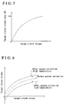
- Fig. 3 is a graph showing a basic relationship of a clutch torque relative to a moving amount of a rod (i.e., a clutch stroke) of the vehicle control system applied to the clutch control device according to the first embodiment of the present invention.
- Fig. 4 is a flow chart showing a control condition of the clutch control device according to the first embodiment of the present invention.
- Fig. 5 is a graph showing a relationship between a clutch temperature and a friction coefficient ⁇ of the vehicle control system applied to the clutch control device according to the first embodiment of the present invention.
- Fig. 6 is a graph showing a relationship between a target clutch torque and a target clutch stroke of the clutch control device before and after a first correction according to the first embodiment of the present invention.
- Fig. 7 is a graph showing a characteristic map related to the target clutch torque and a first correction target clutch stroke rate of the clutch control device according to the first embodiment of the present invention.
- Fig. 8 is a graph showing a relationship between the target clutch torque and the target clutch stroke of the clutch control device before and after a second correction according to the first embodiment of the present invention.
- Fig. 9 is a graph showing a characteristic map related to the target clutch torque and the first correction target clutch stroke rate of the clutch control device before and after a third correction according to the first embodiment of the present invention.
- Fig. 10 is a graph showing a relationship between the target clutch torque and the target clutch stroke for explaining an operation of a conventional clutch control device.
- a clutch control device according to a first embodiment of the present invention will be explained with reference to illustrations of drawings as follows.
- an automatic clutch 20 is assembled to a flywheel 10a which is configured to rotate integrally with an output shaft (i.e., a crank shaft) of an engine 10 (i.e., an internal combustion engine).
- An automatic manual transmission 30 i.e., a transmission is connected to the flywheel 10a through the automatic clutch 20.
- the engine 10 is provided with an ignition switch 11 for an ignition, an engine rotational speed sensor 16 for detecting an engine rotational speed Ne, and an engine water temperature sensor 17 for detecting engine water temperature Tw.
- the automatic clutch 20 includes a mechanical (i.e., dry type - single) friction clutch 21, a clutch lever 22, and a clutch actuator 23 which is configured to control a rotational transmission of the friction clutch 21 through the clutch lever 22.
- the friction clutch 21 includes a clutch disc 21a which is disposed facing the flywheel 10a and is integrally rotatable with an input shaft 31 of the automatic manual transmission 30.
- rotational transmission i.e., a clutch torque
- the clutch actuator 23 is provided with a direct current electric motor 24 (i.e., an electric motor) serving as a driving power source.
- the clutch lever 22 varies its position in response to forward or rearward movement of a rod 25 operated by the motor 24.
- a diaphragm spring 28 is resiliently attached to a release bearing 27 and distorted by the release bearing 27 operated by the clutch lever 22.
- a pressure plate 29 is applied with a pressure load from the distorted diaphragm spring 28.
- the pressure plate 29 is supported by a clutch cover 21b of the friction clutch 21 which is integrally rotatable with the flywheel 10a.
- a relationship between a moved position of the rod 25 and the rotational transmission by the friction clutch 21 is explained as follows.
- the pressure load of the clutch disc 21a relative to the flywheel 10a will eventually become approximately zero.
- the clutch disc 21a is disconnected with the flywheel 10a and there is no rotational transmission between the flywheel 10a and the clutch disc 21a.
- This state of the friction clutch 21 refers to as a clutch disengaged condition and the position of the rod 25 at this time refers to as a standby position.
- the moving amount relative to the position of the rod 25 refers to as a clutch stroke as a control amount.
- the clutch actuator 23 controls the slip amount between the flywheel 10a and the clutch disc 21a by controlling the moving amount (i.e., the clutch stroke) of the rod 25 between the standby position and the moving position of the synchronized rotation (i.e., a clutch fully engaged position).
- a condition where the flywheel 10a and the clutch disc 21a slips when the moving amount (i.e., the clutch stroke) of the rod 25 being part way between the standby position and the fully engaged position refers to as a clutch half-engaged condition. Both the clutch fully engaged condition and the clutch half-engaged condition mean clutch engaged conditions.
- a zero point of the clutch stroke corresponds to the standby position.
- the clutch stroke at the positive side of the zero point corresponds to the moving amount of the rod 25 in the direction of the clutch fully engaged position.
- the clutch torque can be transmitted from the flywheel 10a to the clutch disc 21a.
- the clutch torque is increased in response to the movement of the rod 25 in the direction of the clutch fully engaged position with along to the increase of the clutch stroke.
- the vehicle can be, for example, smoothly started and accurately accelerated by controlling the clutch torque in response to vehicle driving conditions.
- the automatic clutch 20 is provided with a stroke sensor 26 (i.e., a second detecting means) for detecting a clutch stroke St which represents a moving position of the rod 25 of the clutch actuator 23.
- the clutch stroke St serves for judging a condition of the rotational transmission through the friction clutch 21.
- the automatic manual transmission 30 is a parallel axis type gear transmission which performs, for example, five forward shift stages and a single reverse shift stage.
- the automatic manual transmission 30 includes the input shaft 31, an output shaft 32, and plural gear trains.
- the input shaft 31 of the transmission 30 is operatively linked to the clutch disc 21a of the friction clutch 21 and the output shaft 32 of the transmission 30 is operatively linked to an axle (not shown).
- the input shaft 31 is provided with a rotational speed sensor 33 for detecting the rotational speed (i.e., an input shaft rotational speed Ni).
- the automatic manual transmission 30 is provided with a shift actuator 41 for changing gear trains (shift stages) capable of transmitting a driving power.
- the automatic manual transmission 30 selects desirable shift stages by means of the shift actuator 41.
- the vehicle control system illustrated in FIG. 1 is provided with an electronic control unit (i.e., an ECU) 50.
- the ECU 50 includes a detecting means 51 (i.e., a first detecting means), a calculating means 52, and a correcting means 53 (i.e., a first correction means and a second correction means) as illustrated in Fig. 2.
- the detecting means 51 detects the vehicle driving conditions (i.e., a driving speed, the engine water temperature, the engine rotational speed, an input rotational speed, an engine torque, a clutch estimate temperature, and a clutch estimate torque, etc.) on the basis of detecting signals of the various sensors.
- the calculating means 52 calculates numerical information (i.e., the clutch estimate torque, the clutch estimate temperature, a reference target clutch torque, a correction coefficient of the clutch torque temperature, a first correction target clutch torque, a first correction target clutch stroke rate, a first correction target clutch stroke, a corresponding correction amount of the thermal expansion, a second correction target clutch stroke, a back-calculated first correction target clutch stroke, a back-calculated first correction target clutch stroke rate, a back-calculated first correction target clutch torque, and a back-calculated reference target clutch torque, etc.) for the clutch control with reference to, for example, a database and a predetermined characteristic map on the basis of information of the vehicle driving conditions.
- numerical information i.e., the clutch estimate torque, the clutch estimate temperature, a reference target clutch torque, a correction coefficient of the clutch torque temperature, a first correction target clutch torque, a first correction target clutch stroke rate, a first correction target clutch stroke, a corresponding correction amount of the thermal expansion, a second correction target clutch stroke
- the correcting means 53 corrects a control amount of the clutch actuator 23 on the basis of detected clutch temperature. More particularly, the correcting means 53 corrects the control amount of the clutch actuator 23 on the basis of the fluctuation of the friction coefficient ⁇ and the thermal expansion of the clutch disc in response to the clutch temperature.
- the ECU 50 includes main elements such as a well-known central processing unit (i.e., a CPU) with a microcomputer, a read-only-memory (i.e., a ROM) for memorizing various programs, characteristic maps, updated values of the fully engaged position and the standby position, a random-access-memory (i.e., a RAM) for reading out and writing down various data, and an electronically erasable and programmable read only memory (i.e., an EEPROM) for storing data without a back-up power source.
- the ECU 50 is connected with the ignition switch 11, various sensors including the engine rotational speed sensor 16, the engine water temperature sensor 17, the stroke sensor 26, and the rotational speed sensor 33, the clutch actuator 23, and the shift actuator 41.
- the ECU 50 receives the detecting signals of the various sensors so as to detect the vehicle driving conditions (i.e., an on/off condition of the ignition switch 11, the engine rotational speed Ne, the engine water temperature Tw, the clutch stroke St, the input shaft rotational speed Ni, etc.).
- the ECU 50 further operates the clutch actuator 23 and the shift actuator 41 on the basis of the vehicle driving conditions.
- the ECU 50 operates the clutch actuator 23 for adjusting the rotational transmission by the friction clutch 21. Therefore, the rotational transmission by the friction clutch 21 in response to the vehicle driving conditions can be automatically controlled.
- the ECU 50 operates the shift actuator 41 for selecting the gear trains (i.e., the shift stages) capable of transmitting the driving power in the transmission 30. Accordingly, the shift stages in the transmission 30 in response to the vehicle driving conditions can be automatically performed.
- step A1 the ECU 50 calculates the reference target clutch torque.
- the ECU 50 calculates the reference target clutch torque which is suitable for the clutch control in response to the vehicle driving conditions on the basis of the detecting signals of the various sensors.
- the reference target clutch torque refers to as the target clutch torque which is calculated on the assumption that the clutch disc 21a being at a predetermined reference temperature and there being no fluctuation of the friction coefficient ⁇ and the thermal expansion due to the temperature of the clutch disc 21a. Accordingly, the clutch estimate temperature is not considered in step A1. (The vehicle driving conditions in step A1 do not include the clutch estimate temperature).
- the ECU 50 calculates the correction coefficient of the clutch torque temperature with reference to a characteristic map relating to the clutch temperature and the correction coefficient of the clutch torque temperature on the basis of the detected (calculated) clutch estimate temperature (i.e., an estimate temperature of the clutch disc 21a).
- the clutch estimate temperature is calculated with reference to a predetermined characteristic map on the basis of, for example, the clutch estimate toque calculated on the basis of the engine torque and the engine rotational speed, the driving speed, the engine water temperature, the engine rotational speed, and the input rotational speed.
- the clutch stroke detected by the stroke sensor 26 is preferably not to be used as a parameter for the calculation of the clutch estimate temperature so as to avoid a circle consultation of the correction amount.
- the ECU 50 includes an initializing means.
- the parameter used in the calculation of the clutch estimate temperature is desirably initialized by a predetermine timing so as to improve stability of the estimate accuracy and capability of initial driving.
- the correction coefficient of the clutch torque temperature is described as follows. Referring to Fig. 5, when the clutch temperature (i.e., the temperature of the clutch disc 21a) increases beyond a predetermined temperature, the friction coefficient ⁇ is gradually decreased. On the other hand, the relationship of the clutch torque relative to the clutch stroke illustrated in Fig. 3 is assumed that there is no clutch temperature influence. In practice, the clutch torque is estimated by multiplying the clutch load by the friction coefficient ⁇ while the clutch load is estimated on the basis of the clutch stroke. In other words, the relationship of the clutch torque relative to the clutch stroke shown in Fig. 3 is calculated on the assumption that the friction coefficient ⁇ is constant. A correction coefficient of the clutch torque temperature absorbs the influences of the friction coefficient ⁇ in the relationship of the clutch torque relative to the clutch stroke illustrated in Fig.
- the correction coefficient of the clutch torque temperature is calculated so as to increase the target clutch torque in consideration of a decrease of the clutch torque relative to the clutch stroke (i.e., clutch load).
- the correction coefficient of the clutch torque temperature does not consider the influence due to the thermal expansion of the clutch disc.
- step A3 the ECU 50 calculates the first correction target clutch torque on the basis of the calculated reference target clutch torque and the correction coefficient of the clutch torque temperature.
- the ECU 50 calculates the target clutch torque (i.e., the first correction target clutch torque) in light of the influence due to the fluctuation of the friction coefficient ⁇ by multiplying the reference target clutch torque by the correction coefficient of the clutch torque temperature. Multiplication of the reference target clutch torque and the correction coefficient of the clutch torque temperature refers to as a first correction.
- a relationship between the target clutch torque and the target clutch stroke before and after the first correction is illustrated in Fig. 6.
- step A4 the ECU 50 calculates the first correction target clutch stroke rate with reference to a characteristic map related to the target clutch torque and the target clutch stroke rate on the basis of the first correction target clutch torque calculated in step A3.
- the first correction target clutch stroke rate refers to as a ratio of the target clutch stroke in a condition where the clutch stroke of the standby position is assumed to be zero percent and the clutch stroke of the fully engaged position is assumed to be one hundred percent when the correction due to the fluctuation of the friction coefficient ⁇ being made.
- An example of the characteristic map related to the target clutch torque and the target clutch stroke rate is illustrated in Fig. 7.
- step A5 the ECU 50 calculates the first correction target clutch stroke with reference to a position information related to the fully engaged position and the standby position on the basis of the first correction target clutch stroke rate calculated in step A4.
- the first correction target clutch stroke is calculated by multiplying the difference between the fully engaged position and the standby position by the first correction target clutch stroke rate.
- the updated values of the fully engaged position and the standby position which is obtained in a condition where the correction due to the wear of the clutch disc being made, is used for the position information related to the fully engaged position and the standby position.
- step A6 the ECU 50 calculates the corresponding correction amount of the thermal expansion with reference to a characteristic map related to the clutch temperature and the correction amount on the basis of the detected (calculated) clutch estimate temperature.
- the corresponding correction amount of the thermal expansion refers to as a fluctuation amount of the thermal expansion of the clutch disc 21a due to an increase of the clutch disc temperature in a condition where the temperature of the clutch disc 21a being higher than a predetermined reference temperature.
- the corresponding correction amount of the thermal expansion refers to as a fluctuation amount of thermal contraction of the clutch disc 21a due to a decrease of the clutch disc temperature in a condition where the temperature of the clutch disc 21a being lower than a predetermined reference temperature.
- the clutch estimate temperature used in step A6 is same as which used in step A2.
- the corresponding correction amount of the thermal expansion is indicated as a positive value when the clutch disc 21a is thermally expanded, meanwhile, the corresponding correction amount of the thermal expansion is indicated as a negative value when the clutch disc 21a is thermally contracted.
- step A7 the ECU 50 calculates the second correction target clutch stroke on the basis of the first correction target clutch stroke calculated in step A5 and the corresponding correction amount of the thermal expansion calculated in step A6.
- the second correction target clutch stroke refers to as the clutch stroke in light of the influence due to the fluctuation of the friction coefficient ⁇ and the thermal expansion.
- the second correction target clutch stroke is calculated by adding the corresponding correction amount of the thermal expansion to the first correction target clutch stroke.
- An addition of the first correction target clutch stroke and the corresponding correction amount of the thermal expansion refers to as a second correction.
- a relationship between the target clutch torque and the target clutch stroke before and after the second correction is illustrated in Fig. 8.
- the target clutch stroke shifts upward in Fig. 8 when the clutch temperature is higher than the reference temperature and the clutch disc is thermally expanded.
- the target clutch stroke shifts downward in Fig. 8 when the clutch temperature is lower than the reference temperature and the clutch disc is thermally contracted.
- step A8 the ECU 50 performs a feed back operation so as to make the clutch stroke St detected by the stroke sensor 26 substantially match with the second correction target clutch stroke calculated in step A7. Accordingly, the clutch control system is achieved which absorbs the influence due to the fluctuation of the friction coefficient ⁇ and the thermal expansion of the clutch disc.
- step A9 the ECU 50 calculates the back-calculated first correction target clutch stroke on the basis of the detected clutch stroke St and the calculated corresponding correction amount of the thermal expansion.
- the back-calculated first correction target clutch stroke is calculated by calculating back the first correction target clutch stroke on the basis of the clutch stroke St and the corresponding correction amount of the thermal expansion. That is, the back-calculated first correction target is calculated by subtracting the corresponding correction amount of the thermal expansion from the clutch stroke St.
- the corresponding correction amount of the thermal expansion used in step A9 is calculated in step A6 and same as which used in step 7.
- step A10 the ECU 50 calculates the back-calculated first correction target clutch stroke rate with reference to the position information related to the fully engaged position and the standby position on the basis of the back-calculated first correction target clutch stroke calculated in step A9.
- the back-calculated first correction target clutch stroke rate is calculated by calculating back the first correction target clutch stroke rate on the basis of the position information (i.e. the updated values) related to the fully engaged position and the standby position. That is, the back-calculated first correction target clutch stroke rate is calculated by dividing the back-calculated first correction target clutch stroke by the difference between the fully engaged position and the standby position.
- step A11 the ECU 50 calculates the back-calculated first correction target clutch torque with reference to the characteristic map related to the target clutch torque and the target clutch stroke rate on the basis of the back-calculated first correction target clutch stroke rate calculated in step A10.
- the back-calculated first correction target clutch torque is calculated by calculating back the first correction target clutch torque corresponding to the back-calculated first correction target clutch stroke rate from the characteristic map related to the target clutch torque and the target clutch stroke rate.
- the characteristic map related to the target clutch torque and the target clutch stroke rate used in this step is same as which used in step A4.
- step A12 the ECU 50 calculates the back-calculated reference target clutch torque on the basis of the back-calculated first correction target clutch torque and the correction coefficient of the clutch torque temperature.
- the back-calculated reference target clutch torque is calculated by calculating back the reference target clutch torque on the basis of the back-calculated first correction target clutch torque and the correction coefficient of the clutch torque temperature. That is, the back-calculated reference target clutch torque is calculated by dividing the back-calculated first correction target clutch torque by the correction coefficient of the clutch torque temperature.
- the correction coefficient of the clutch torque temperature used in step A12 is same as which used in step A3.
- step A13 the ECU 50 corrects the characteristic map related to the target clutch torque and the target clutch stroke rate on the basis of the back-calculated reference target clutch torque and the clutch estimate torque.
- This correction refers to as a multipoint correction or a third correction.
- the clutch estimate torque is calculated on the basis of the engine torque and the engine rotational speed.
- a characteristic map related to the corrected target clutch torque and the target clutch stroke rate would be used in step A4 and step A11 of next routine.
- An image of the target clutch torque and the target clutch stroke rate before and after the third correction is illustrated in Fig. 9. The operation is temporarily terminated after step A13.
- the first embodiment of the present invention and known arts are compared with an example of the clutch torque in a condition where the clutch torque desirably be controlled at 20 Nm.
- optimal moving amount of the actual clutch stroke in the direction of the clutch engaged position from the first correction target clutch torque of 20Nm is calculated by using the characteristic map.
- the first correction target clutch stroke is assumed to be 4.5mm.
- An error of the clutch stroke in practice becomes 10Nm when the clutch torque is assumed to be 30Nm in a condition where the clutch stroke is 5.0mm.
- the clutch is desired to be engaged in a condition where the first correction target clutch torque being 20Nm and the first correction target clutch stroke being 4.5mm.
- the target clutch torque (i.e., the target clutch stroke) is corrected on the basis of the estimated clutch temperature.
- the target clutch torque i.e., the target clutch stroke
- the optimal clutch torque feed back operation can be performed by absorbing the influence on the clutch torque due to the clutch temperature on the basis of the corrected target clutch torque (i.e., the target clutch stroke).
- the clutch control device of the present invention performs the clutch temperature correction not only at low temperature, but also at any temperature including high temperature period. Further, the clutch control device calculates the clutch estimate temperature by using the clutch estimate torque calculated on the basis of the engine torque and the engine rotational speed so as to avoid divergence of the correction.
- the clutch actuator 23 is provided for varying the clutch lever 22 by forward and rearward movement of the rod 25.
- the clutch actuator which operates the release bearing 27, the diaphragm spring 28, and the pressure plate 29, may be provided for controlling the clutch torque.
- the clutch temperature is estimated in response to the vehicle driving conditions.
- the clutch disc 21a may be provided with a temperature detecting sensor for detecting the clutch temperature directly.
- the optimal clutch torque feedback operation can be performed since the target clutch torque (i.e., the target clutch stroke) is corrected to absorb the influence due to the fluctuation of the friction coefficient ⁇ and the thermal expansion of the clutch disc on the basis of the clutch temperature.
- the target clutch torque is calculated (back calculation) on the basis of the clutch stroke (i.e., the actual clutch stroke) detected by the detecting means so as to estimate an accurate clutch torque.
- the clutch stroke detected by the detecting means is not used as a parameter in the calculation of the clutch estimate temperature so as to avoid a circle consultation of the correction amount. Therefore, the improvement of stability of the estimate accuracy is achieved.
- the parameter is initialized by the predetermine timing so as to achieve the improvement of stability of the estimate accuracy and capability of the initial driving.
- the initial driving refers to as the driving in a little while after the ignition switch be turned on.
Applications Claiming Priority (1)
| Application Number | Priority Date | Filing Date | Title |
|---|---|---|---|
| JP2004245881A JP4715132B2 (ja) | 2004-08-25 | 2004-08-25 | クラッチ制御装置 |
Publications (2)
| Publication Number | Publication Date |
|---|---|
| EP1630442A1 true EP1630442A1 (de) | 2006-03-01 |
| EP1630442B1 EP1630442B1 (de) | 2010-11-17 |
Family
ID=35240956
Family Applications (1)
| Application Number | Title | Priority Date | Filing Date |
|---|---|---|---|
| EP05017306A Expired - Fee Related EP1630442B1 (de) | 2004-08-25 | 2005-08-09 | Kupplungssteuerungsvorrichtung |
Country Status (3)
| Country | Link |
|---|---|
| EP (1) | EP1630442B1 (de) |
| JP (1) | JP4715132B2 (de) |
| DE (1) | DE602005024747D1 (de) |
Cited By (15)
| Publication number | Priority date | Publication date | Assignee | Title |
|---|---|---|---|---|
| FR2901335A1 (fr) * | 2006-05-22 | 2007-11-23 | Peugeot Citroen Automobiles Sa | Procede de pilotage d'un embrayage robotise. |
| WO2008000598A1 (de) * | 2006-06-29 | 2008-01-03 | Zf Friedrichshafen Ag | Verfahren zur steuerung einer automatisierten reibungskupplung |
| FR2907867A1 (fr) * | 2006-10-25 | 2008-05-02 | Peugeot Citroen Automobiles Sa | Systeme et procede d'estimation d'un couple transmis par un embrayage a friction de vehicule automobile |
| FR2908484A1 (fr) * | 2006-11-10 | 2008-05-16 | Peugeot Citroen Automobiles Sa | Procede et systeme de diagnostic de l'etat de fonctionnement d'un embrayage a friction seche de vehicule automobile. |
| FR2920382A1 (fr) * | 2007-08-31 | 2009-03-06 | Renault Sas | Dispositif et procede de determination d'une cartographie du couple transmis par un embrayage equipant un vehicule automobile. |
| EP2116735A1 (de) * | 2007-02-08 | 2009-11-11 | Univance Corporation | Steuervorrichtung für lamellenkupplung und übertragungsvorrichtung |
| WO2009146815A1 (de) * | 2008-06-03 | 2009-12-10 | Magna Powertrain Ag & Co Kg | Verfahren zum steuern einer kupplungseinheit |
| WO2010020523A1 (de) * | 2008-08-19 | 2010-02-25 | Robert Bosch Gmbh | Verfahren zur kompensation von volumenänderungen eines hydraulikfluids in einer hydraulischen betätigungseinrichtung zur betätigung einer kupplung, sowie hydraulische betätigungseinrichtung |
| WO2010043471A1 (de) * | 2008-10-16 | 2010-04-22 | Robert Bosch Gmbh | Verfahren zur automatischen tastpunktadaption |
| EP2192319A1 (de) * | 2008-12-01 | 2010-06-02 | GM Global Technology Operations, Inc. | Kupplungssystem |
| US20100138121A1 (en) * | 2008-12-03 | 2010-06-03 | C.R.F. Societa' Consortile Per Azioni | Method of controlling a friction clutch in a motor-vehicle transmission |
| US20110004380A1 (en) * | 2008-03-31 | 2011-01-06 | Honda Motor Co., Ltd. | CLUTCH CONTROL DEVICE AND µ CORRECTION COEFFICIENT CALCULATING METHOD |
| FR2998346A1 (fr) * | 2012-11-20 | 2014-05-23 | Peugeot Citroen Automobiles Sa | Procede et dispositif de conversion d'une consigne de couple devant etre transmis par un embrayage en une consigne de position d'actionneur |
| EP3135945A1 (de) * | 2014-04-25 | 2017-03-01 | Aisin Seiki Kabushiki Kaisha | Vorrichtung zur steuerung einer fahrzeugantriebskraft |
| DE102017129571A1 (de) | 2017-12-12 | 2019-06-13 | Schaeffler Technologies AG & Co. KG | Temperaturmodell für Hybridmodul und Verfahren zum Schutz eines Hybridmoduls |
Families Citing this family (6)
| Publication number | Priority date | Publication date | Assignee | Title |
|---|---|---|---|---|
| JP2008057575A (ja) * | 2006-08-29 | 2008-03-13 | Aisin Seiki Co Ltd | マニュアルトランスミッションの自動変速用アクチュエータ |
| JP5471981B2 (ja) * | 2010-09-02 | 2014-04-16 | トヨタ自動車株式会社 | 車両用自動クラッチの制御装置 |
| JP5630229B2 (ja) * | 2010-11-15 | 2014-11-26 | トヨタ自動車株式会社 | 車両用摩擦クラッチの制御装置 |
| JP2014214678A (ja) | 2013-04-25 | 2014-11-17 | アイシン精機株式会社 | 車両用駆動装置 |
| JP6260202B2 (ja) * | 2013-10-31 | 2018-01-17 | アイシン精機株式会社 | 動力伝達装置およびクラッチ駆動制御装置 |
| KR101655692B1 (ko) * | 2015-07-07 | 2016-09-08 | 현대자동차주식회사 | 차량의 클러치 과열 방지방법 |
Citations (3)
| Publication number | Priority date | Publication date | Assignee | Title |
|---|---|---|---|---|
| DE4124722A1 (de) * | 1991-07-25 | 1993-01-28 | Steyr Daimler Puch Ag | Einrichtung und verfahren zum schutz einer reibungskupplung vor thermischer ueberlastung |
| EP1416182A2 (de) * | 2002-10-30 | 2004-05-06 | Aisin Seiki Kabushiki Kaisha | Kupplungssteuerung |
| FR2854848A1 (fr) * | 2003-05-14 | 2004-11-19 | Valeo Embrayages | Dispositif adaptatif pilote d'accouplement entre un moteur et une boite de vitesse dans un vehicule automobile |
Family Cites Families (2)
| Publication number | Priority date | Publication date | Assignee | Title |
|---|---|---|---|---|
| JPH0379850A (ja) * | 1989-08-19 | 1991-04-04 | Toyota Autom Loom Works Ltd | 変速機の制御装置 |
| JP4178865B2 (ja) * | 2002-07-29 | 2008-11-12 | アイシン精機株式会社 | クラッチ制御装置 |
-
2004
- 2004-08-25 JP JP2004245881A patent/JP4715132B2/ja not_active Expired - Fee Related
-
2005
- 2005-08-09 EP EP05017306A patent/EP1630442B1/de not_active Expired - Fee Related
- 2005-08-09 DE DE602005024747T patent/DE602005024747D1/de active Active
Patent Citations (4)
| Publication number | Priority date | Publication date | Assignee | Title |
|---|---|---|---|---|
| DE4124722A1 (de) * | 1991-07-25 | 1993-01-28 | Steyr Daimler Puch Ag | Einrichtung und verfahren zum schutz einer reibungskupplung vor thermischer ueberlastung |
| EP1416182A2 (de) * | 2002-10-30 | 2004-05-06 | Aisin Seiki Kabushiki Kaisha | Kupplungssteuerung |
| JP2004150513A (ja) | 2002-10-30 | 2004-05-27 | Aisin Seiki Co Ltd | クラッチ制御装置 |
| FR2854848A1 (fr) * | 2003-05-14 | 2004-11-19 | Valeo Embrayages | Dispositif adaptatif pilote d'accouplement entre un moteur et une boite de vitesse dans un vehicule automobile |
Cited By (27)
| Publication number | Priority date | Publication date | Assignee | Title |
|---|---|---|---|---|
| FR2901335A1 (fr) * | 2006-05-22 | 2007-11-23 | Peugeot Citroen Automobiles Sa | Procede de pilotage d'un embrayage robotise. |
| WO2008000598A1 (de) * | 2006-06-29 | 2008-01-03 | Zf Friedrichshafen Ag | Verfahren zur steuerung einer automatisierten reibungskupplung |
| FR2907867A1 (fr) * | 2006-10-25 | 2008-05-02 | Peugeot Citroen Automobiles Sa | Systeme et procede d'estimation d'un couple transmis par un embrayage a friction de vehicule automobile |
| FR2908484A1 (fr) * | 2006-11-10 | 2008-05-16 | Peugeot Citroen Automobiles Sa | Procede et systeme de diagnostic de l'etat de fonctionnement d'un embrayage a friction seche de vehicule automobile. |
| EP2116735A1 (de) * | 2007-02-08 | 2009-11-11 | Univance Corporation | Steuervorrichtung für lamellenkupplung und übertragungsvorrichtung |
| EP2116735A4 (de) * | 2007-02-08 | 2012-11-21 | Univance Corp | Steuervorrichtung für lamellenkupplung und übertragungsvorrichtung |
| FR2920382A1 (fr) * | 2007-08-31 | 2009-03-06 | Renault Sas | Dispositif et procede de determination d'une cartographie du couple transmis par un embrayage equipant un vehicule automobile. |
| WO2009030848A1 (fr) * | 2007-08-31 | 2009-03-12 | Renault S.A.S. | Dispositif et procede de determination d'une cartographie du couple transmis par un embrayage equipant un vehicule automobile et systeme d'assistance a un demarrage en cote d'un vehicule automobile equipe d'un tel dispositif |
| CN101842608A (zh) * | 2007-08-31 | 2010-09-22 | 雷诺股份公司 | 用于确定由汽车的离合器传输的扭矩的一种映射的装置和方法以及用于装备有这种装置的汽车的坡启动辅助系统 |
| US8515640B2 (en) | 2007-08-31 | 2013-08-20 | Renault S. A. S. | Device and method for determining a mapping of the torque transmitted by a clutch in an automobile and hill-start assistance system for an automobile equipped with such device |
| US20110004380A1 (en) * | 2008-03-31 | 2011-01-06 | Honda Motor Co., Ltd. | CLUTCH CONTROL DEVICE AND µ CORRECTION COEFFICIENT CALCULATING METHOD |
| US8612104B2 (en) * | 2008-03-31 | 2013-12-17 | Honda Motor Co., Ltd. | Clutch control device and μ correction coefficient calculating method |
| WO2009146815A1 (de) * | 2008-06-03 | 2009-12-10 | Magna Powertrain Ag & Co Kg | Verfahren zum steuern einer kupplungseinheit |
| DE102008026554B4 (de) | 2008-06-03 | 2022-12-15 | Magna powertrain gmbh & co kg | Verfahren zum Steuern einer Kupplungseinheit, sowie Drehmomentübertragungsanordnung |
| US8645036B2 (en) | 2008-06-03 | 2014-02-04 | Magna Powertrain Ag & Co Kg | Method for controlling a clutch unit |
| WO2010020523A1 (de) * | 2008-08-19 | 2010-02-25 | Robert Bosch Gmbh | Verfahren zur kompensation von volumenänderungen eines hydraulikfluids in einer hydraulischen betätigungseinrichtung zur betätigung einer kupplung, sowie hydraulische betätigungseinrichtung |
| WO2010043471A1 (de) * | 2008-10-16 | 2010-04-22 | Robert Bosch Gmbh | Verfahren zur automatischen tastpunktadaption |
| EP2192319A1 (de) * | 2008-12-01 | 2010-06-02 | GM Global Technology Operations, Inc. | Kupplungssystem |
| WO2010063337A1 (en) * | 2008-12-01 | 2010-06-10 | Gm Global Technology Operations, Inc. | Clutch system |
| EP2194287A1 (de) * | 2008-12-03 | 2010-06-09 | C.R.F. Società Consortile per Azioni | Verfahren zur Steuerung einer Reibungskupplung in einem Kraftfahrzeugantriebsstrang |
| CN101749414B (zh) * | 2008-12-03 | 2013-12-11 | C.R.F.阿西安尼顾问公司 | 一种控制机动车辆传动装置中的摩擦离合器的方法 |
| US8571767B2 (en) | 2008-12-03 | 2013-10-29 | Crf Societa Consortile Per Azioni | Method of controlling a friction clutch in a motor-vehicle transmission |
| US20100138121A1 (en) * | 2008-12-03 | 2010-06-03 | C.R.F. Societa' Consortile Per Azioni | Method of controlling a friction clutch in a motor-vehicle transmission |
| FR2998346A1 (fr) * | 2012-11-20 | 2014-05-23 | Peugeot Citroen Automobiles Sa | Procede et dispositif de conversion d'une consigne de couple devant etre transmis par un embrayage en une consigne de position d'actionneur |
| EP3135945A1 (de) * | 2014-04-25 | 2017-03-01 | Aisin Seiki Kabushiki Kaisha | Vorrichtung zur steuerung einer fahrzeugantriebskraft |
| EP3135945A4 (de) * | 2014-04-25 | 2017-04-26 | Aisin Seiki Kabushiki Kaisha | Vorrichtung zur steuerung einer fahrzeugantriebskraft |
| DE102017129571A1 (de) | 2017-12-12 | 2019-06-13 | Schaeffler Technologies AG & Co. KG | Temperaturmodell für Hybridmodul und Verfahren zum Schutz eines Hybridmoduls |
Also Published As
| Publication number | Publication date |
|---|---|
| JP4715132B2 (ja) | 2011-07-06 |
| DE602005024747D1 (de) | 2010-12-30 |
| JP2006064039A (ja) | 2006-03-09 |
| EP1630442B1 (de) | 2010-11-17 |
Similar Documents
| Publication | Publication Date | Title |
|---|---|---|
| EP1630442B1 (de) | Kupplungssteuerungsvorrichtung | |
| US6050379A (en) | Algorithm for electro-mechanical clutch actuator | |
| EP0572951B1 (de) | Vorrichtung zur Feststellung einer Referenzposition eines servogesteuerten Stellgliedes | |
| US8131438B2 (en) | Method for controlling an automated friction clutch | |
| US7384358B2 (en) | Automatic transmission control apparatus | |
| EP1496281A1 (de) | Kupplungssteuerungsvorrichtung | |
| EP1416182B1 (de) | Kupplungssteuerung | |
| US8202200B2 (en) | Clutch control device | |
| JP4542307B2 (ja) | クラッチ制御装置 | |
| JP4178865B2 (ja) | クラッチ制御装置 | |
| WO2017051733A1 (ja) | 車両用駆動装置 | |
| JP2004197842A (ja) | クラッチ制御装置 | |
| US6581488B2 (en) | Control device for an actuator applied in a transmission | |
| KR101876871B1 (ko) | 다단 자동변속기의 클러치 마찰계수 학습 제어 장치 및 방법, 그리고 클러치 마찰계수 학습 제어 장치를 포함하는 다단 자동변속기 | |
| EP1375950B1 (de) | Kupplungssteuerungsgerät | |
| EP1384912B1 (de) | Kupplungssteuerungvorrichtung | |
| US6431338B1 (en) | Clutch apparatus | |
| JP2008185217A (ja) | クラッチ制御装置 | |
| JP5030634B2 (ja) | クラッチ制御装置 | |
| EP1437255B1 (de) | Steuerungssystem einer automatischen Kupplung | |
| JP2005273875A (ja) | クラッチ制御装置 | |
| JP4910852B2 (ja) | 車両の制御装置 | |
| CN109555796B (zh) | 用于控制车辆的离合器的方法 | |
| EP1245850B1 (de) | Kupplungsteuereinrichtung | |
| JP4175305B2 (ja) | 自動変速機の変速過渡制御装置 |
Legal Events
| Date | Code | Title | Description |
|---|---|---|---|
| PUAI | Public reference made under article 153(3) epc to a published international application that has entered the european phase |
Free format text: ORIGINAL CODE: 0009012 |
|
| AK | Designated contracting states |
Kind code of ref document: A1 Designated state(s): AT BE BG CH CY CZ DE DK EE ES FI FR GB GR HU IE IS IT LI LT LU LV MC NL PL PT RO SE SI SK TR |
|
| AX | Request for extension of the european patent |
Extension state: AL BA HR MK YU |
|
| 17P | Request for examination filed |
Effective date: 20060831 |
|
| AKX | Designation fees paid |
Designated state(s): DE FR GB |
|
| 17Q | First examination report despatched |
Effective date: 20081107 |
|
| GRAP | Despatch of communication of intention to grant a patent |
Free format text: ORIGINAL CODE: EPIDOSNIGR1 |
|
| GRAS | Grant fee paid |
Free format text: ORIGINAL CODE: EPIDOSNIGR3 |
|
| GRAA | (expected) grant |
Free format text: ORIGINAL CODE: 0009210 |
|
| AK | Designated contracting states |
Kind code of ref document: B1 Designated state(s): DE FR GB |
|
| REG | Reference to a national code |
Ref country code: GB Ref legal event code: FG4D |
|
| REF | Corresponds to: |
Ref document number: 602005024747 Country of ref document: DE Date of ref document: 20101230 Kind code of ref document: P |
|
| PLBE | No opposition filed within time limit |
Free format text: ORIGINAL CODE: 0009261 |
|
| STAA | Information on the status of an ep patent application or granted ep patent |
Free format text: STATUS: NO OPPOSITION FILED WITHIN TIME LIMIT |
|
| 26N | No opposition filed |
Effective date: 20110818 |
|
| REG | Reference to a national code |
Ref country code: DE Ref legal event code: R097 Ref document number: 602005024747 Country of ref document: DE Effective date: 20110818 |
|
| REG | Reference to a national code |
Ref country code: FR Ref legal event code: PLFP Year of fee payment: 12 |
|
| REG | Reference to a national code |
Ref country code: FR Ref legal event code: PLFP Year of fee payment: 13 |
|
| REG | Reference to a national code |
Ref country code: FR Ref legal event code: PLFP Year of fee payment: 14 |
|
| REG | Reference to a national code |
Ref country code: DE Ref legal event code: R084 Ref document number: 602005024747 Country of ref document: DE |
|
| REG | Reference to a national code |
Ref country code: GB Ref legal event code: 746 Effective date: 20181228 |
|
| PGFP | Annual fee paid to national office [announced via postgrant information from national office to epo] |
Ref country code: FR Payment date: 20210714 Year of fee payment: 17 |
|
| PGFP | Annual fee paid to national office [announced via postgrant information from national office to epo] |
Ref country code: GB Payment date: 20210701 Year of fee payment: 17 Ref country code: DE Payment date: 20210630 Year of fee payment: 17 |
|
| REG | Reference to a national code |
Ref country code: DE Ref legal event code: R119 Ref document number: 602005024747 Country of ref document: DE |
|
| GBPC | Gb: european patent ceased through non-payment of renewal fee |
Effective date: 20220809 |
|
| PG25 | Lapsed in a contracting state [announced via postgrant information from national office to epo] |
Ref country code: FR Free format text: LAPSE BECAUSE OF NON-PAYMENT OF DUE FEES Effective date: 20220831 Ref country code: DE Free format text: LAPSE BECAUSE OF NON-PAYMENT OF DUE FEES Effective date: 20230301 |
|
| PG25 | Lapsed in a contracting state [announced via postgrant information from national office to epo] |
Ref country code: GB Free format text: LAPSE BECAUSE OF NON-PAYMENT OF DUE FEES Effective date: 20220809 |