EP1629261B1 - Apparatus and method of belt dynamic tension measurement - Google Patents
Apparatus and method of belt dynamic tension measurement Download PDFInfo
- Publication number
- EP1629261B1 EP1629261B1 EP04753319A EP04753319A EP1629261B1 EP 1629261 B1 EP1629261 B1 EP 1629261B1 EP 04753319 A EP04753319 A EP 04753319A EP 04753319 A EP04753319 A EP 04753319A EP 1629261 B1 EP1629261 B1 EP 1629261B1
- Authority
- EP
- European Patent Office
- Prior art keywords
- transducer
- torque
- hubload
- belt
- ring
- Prior art date
- Legal status (The legal status is an assumption and is not a legal conclusion. Google has not performed a legal analysis and makes no representation as to the accuracy of the status listed.)
- Expired - Lifetime
Links
- 238000000034 method Methods 0.000 title claims abstract description 15
- 238000005259 measurement Methods 0.000 title description 11
- 239000013598 vector Substances 0.000 description 17
- 238000009434 installation Methods 0.000 description 11
- 230000035945 sensitivity Effects 0.000 description 9
- 238000010586 diagram Methods 0.000 description 8
- 238000012360 testing method Methods 0.000 description 8
- 239000000463 material Substances 0.000 description 7
- 239000004033 plastic Substances 0.000 description 6
- 239000000853 adhesive Substances 0.000 description 4
- 230000001070 adhesive effect Effects 0.000 description 4
- 230000005284 excitation Effects 0.000 description 4
- 230000036961 partial effect Effects 0.000 description 4
- 239000007769 metal material Substances 0.000 description 3
- XLYOFNOQVPJJNP-UHFFFAOYSA-N water Substances O XLYOFNOQVPJJNP-UHFFFAOYSA-N 0.000 description 3
- FYYHWMGAXLPEAU-UHFFFAOYSA-N Magnesium Chemical compound [Mg] FYYHWMGAXLPEAU-UHFFFAOYSA-N 0.000 description 2
- 229910000831 Steel Inorganic materials 0.000 description 2
- RTAQQCXQSZGOHL-UHFFFAOYSA-N Titanium Chemical compound [Ti] RTAQQCXQSZGOHL-UHFFFAOYSA-N 0.000 description 2
- 239000000956 alloy Substances 0.000 description 2
- 229910045601 alloy Inorganic materials 0.000 description 2
- 229910052782 aluminium Inorganic materials 0.000 description 2
- XAGFODPZIPBFFR-UHFFFAOYSA-N aluminium Chemical compound [Al] XAGFODPZIPBFFR-UHFFFAOYSA-N 0.000 description 2
- 229910010293 ceramic material Inorganic materials 0.000 description 2
- 230000007423 decrease Effects 0.000 description 2
- 230000001419 dependent effect Effects 0.000 description 2
- 238000013461 design Methods 0.000 description 2
- 238000004134 energy conservation Methods 0.000 description 2
- 238000010348 incorporation Methods 0.000 description 2
- WABPQHHGFIMREM-UHFFFAOYSA-N lead(0) Chemical compound [Pb] WABPQHHGFIMREM-UHFFFAOYSA-N 0.000 description 2
- 239000011777 magnesium Substances 0.000 description 2
- 229910052749 magnesium Inorganic materials 0.000 description 2
- 238000012986 modification Methods 0.000 description 2
- 230000004048 modification Effects 0.000 description 2
- 230000002829 reductive effect Effects 0.000 description 2
- 230000003068 static effect Effects 0.000 description 2
- 239000010959 steel Substances 0.000 description 2
- 239000010936 titanium Substances 0.000 description 2
- 229910052719 titanium Inorganic materials 0.000 description 2
- 229920002943 EPDM rubber Polymers 0.000 description 1
- 244000043261 Hevea brasiliensis Species 0.000 description 1
- 238000004378 air conditioning Methods 0.000 description 1
- 230000005540 biological transmission Effects 0.000 description 1
- 239000000919 ceramic Substances 0.000 description 1
- 238000006243 chemical reaction Methods 0.000 description 1
- 230000006835 compression Effects 0.000 description 1
- 238000007906 compression Methods 0.000 description 1
- 238000010276 construction Methods 0.000 description 1
- 238000005336 cracking Methods 0.000 description 1
- 125000004122 cyclic group Chemical group 0.000 description 1
- 238000013016 damping Methods 0.000 description 1
- 238000011161 development Methods 0.000 description 1
- 230000009977 dual effect Effects 0.000 description 1
- 229920006168 hydrated nitrile rubber Polymers 0.000 description 1
- 230000000670 limiting effect Effects 0.000 description 1
- 238000000691 measurement method Methods 0.000 description 1
- 229910052751 metal Inorganic materials 0.000 description 1
- 239000002184 metal Substances 0.000 description 1
- 229920003052 natural elastomer Polymers 0.000 description 1
- 229920001194 natural rubber Polymers 0.000 description 1
- 230000010355 oscillation Effects 0.000 description 1
- ISWSIDIOOBJBQZ-UHFFFAOYSA-N phenol group Chemical group C1(=CC=CC=C1)O ISWSIDIOOBJBQZ-UHFFFAOYSA-N 0.000 description 1
- 239000012255 powdered metal Substances 0.000 description 1
- 230000000717 retained effect Effects 0.000 description 1
- 229920003051 synthetic elastomer Polymers 0.000 description 1
- 239000005061 synthetic rubber Substances 0.000 description 1
- 238000003466 welding Methods 0.000 description 1
Images


Classifications
-
- G—PHYSICS
- G01—MEASURING; TESTING
- G01L—MEASURING FORCE, STRESS, TORQUE, WORK, MECHANICAL POWER, MECHANICAL EFFICIENCY, OR FLUID PRESSURE
- G01L5/00—Apparatus for, or methods of, measuring force, work, mechanical power, or torque, specially adapted for specific purposes
- G01L5/04—Apparatus for, or methods of, measuring force, work, mechanical power, or torque, specially adapted for specific purposes for measuring tension in flexible members, e.g. ropes, cables, wires, threads, belts or bands
- G01L5/10—Apparatus for, or methods of, measuring force, work, mechanical power, or torque, specially adapted for specific purposes for measuring tension in flexible members, e.g. ropes, cables, wires, threads, belts or bands using electrical means
-
- G—PHYSICS
- G01—MEASURING; TESTING
- G01L—MEASURING FORCE, STRESS, TORQUE, WORK, MECHANICAL POWER, MECHANICAL EFFICIENCY, OR FLUID PRESSURE
- G01L3/00—Measuring torque, work, mechanical power, or mechanical efficiency, in general
- G01L3/02—Rotary-transmission dynamometers
- G01L3/04—Rotary-transmission dynamometers wherein the torque-transmitting element comprises a torsionally-flexible shaft
- G01L3/10—Rotary-transmission dynamometers wherein the torque-transmitting element comprises a torsionally-flexible shaft involving electric or magnetic means for indicating
- G01L3/108—Rotary-transmission dynamometers wherein the torque-transmitting element comprises a torsionally-flexible shaft involving electric or magnetic means for indicating involving resistance strain gauges
-
- G—PHYSICS
- G01—MEASURING; TESTING
- G01L—MEASURING FORCE, STRESS, TORQUE, WORK, MECHANICAL POWER, MECHANICAL EFFICIENCY, OR FLUID PRESSURE
- G01L1/00—Measuring force or stress, in general
- G01L1/20—Measuring force or stress, in general by measuring variations in ohmic resistance of solid materials or of electrically-conductive fluids; by making use of electrokinetic cells, i.e. liquid-containing cells wherein an electrical potential is produced or varied upon the application of stress
- G01L1/22—Measuring force or stress, in general by measuring variations in ohmic resistance of solid materials or of electrically-conductive fluids; by making use of electrokinetic cells, i.e. liquid-containing cells wherein an electrical potential is produced or varied upon the application of stress using resistance strain gauges
-
- G—PHYSICS
- G01—MEASURING; TESTING
- G01L—MEASURING FORCE, STRESS, TORQUE, WORK, MECHANICAL POWER, MECHANICAL EFFICIENCY, OR FLUID PRESSURE
- G01L3/00—Measuring torque, work, mechanical power, or mechanical efficiency, in general
- G01L3/02—Rotary-transmission dynamometers
- G01L3/04—Rotary-transmission dynamometers wherein the torque-transmitting element comprises a torsionally-flexible shaft
- G01L3/10—Rotary-transmission dynamometers wherein the torque-transmitting element comprises a torsionally-flexible shaft involving electric or magnetic means for indicating
Definitions
- the invention relates to a method of belt dynamic tension measurement and more particularly to a method of belt dynamic tension measurement for drive efficiency measurement using a hubload transducer and a torque transducer.
- strain measuring devices can generally comprise a strainable member to which a load is imparted and to which a strain gage is fixed.
- devices which comprise an annular gage ring having strainable beam members and flexing beam members.
- the flexible beam members interconnect ring portions.
- dual beam sensing members which include spaced end wall members connected integrally by parallel spaced beam members, which beam members are relatively flexible or bendable in one direction only.
- One of the end walls is generally attached to a support structure and the other end wall is operatively or directly attached to a shaft.
- pulleys for measuring torque loads comprising a cylindrical shape connected to a pulley with the other end connected to a shaft and having strain gages attached to the cylindrical shape.
- Japanese patent application publication number 2001099271 which discloses a cylindrical shape connected to a pulley with the other end connected to a shaft and having strain gages attached to the cylindrical shape.
- GB2304902 discloses a hubload transducer as well as torgue transducers.
- the prior art does not teach hubload and torque transducers combined to operate on a system basis. Further, the hubload transducers are relatively complex comprising flexing beam members and strainable beam members. The prior art torque transducer lacks means to torsionally isolate the cylindrical portion from the other supporting structures.
- the invention solves these problems with a method according to claim 1.
- the primary aspect is to provide a method and apparatus for measuring an operating belt span tension and a crankshaft torque using a hubload transducer and a torque transducer.
- Another aspect is to provide a method and apparatus for measuring a belt drive efficiency using a hubload transducer and a torque transducer.
- the invention comprises a method for measuring an operating front end accessory belt tension using a hubload transducer and a torque transducer.
- the hubload transducer comprises concentric rings with a strainable member disposed in a coplanar fashion between an inner and outer ring.
- the hubload transducer is used with a non-torque transmitting idler pulley.
- the torque transducer comprises a strainable cylindrical member connected to a belt bearing surface and a rotating shaft.
- the torque transducer will transmit a torque to a driven accessory. It is used on accessories such as an air conditioner compressor or power steering pump. Signals from the hubload transducer and torque transducer are used to calculate a drive efficiency as well as belt span tensions between the driver and driven accessories.
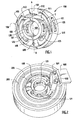
- Fig. 1 is a perspective view of the hubload transducer.
- the hubload transducer is relatively compact and may be used in a pulley to measure a shaft load or shaft dynamic behavior. This includes measuring a hubload and thereby a belt span tension.
- a hubload is a load applied to a pulley and its shaft by a belt tension in a belt drive system.
- Transducer 100 generally comprises an arcuate inner member or hub ring 101, sensor ring 102 and arcuate outer member or outer ring 103.
- Hub ring 101 comprises a bore 104 which acts as a means for attaching the transducer to a mounting surface.
- a fastener such as a bolt engages hub ring 101 through bore 104 to connect the transducer to a mounting surface.
- Hub ring 101 is relatively rigid to provide a firm means of connecting the transducer to the mounting surface.
- Hub ring 101 may also comprise an integral shaft for attaching the hub ring to a mounting surface.
- Hub ring 101 is connected to sensor ring 102 by connecting portion or member 108.
- Apertures 120 and 121 in each side of hub ring 101 provide access to an inner surface 122, 123, of sensor ring 102. Access through apertures 120 and 121 is used for mounting strain gages 302 and 303 to sensor ring 102. Use of apertures 120 and 121 is dependent upon the width of a slot 511. Incorporation of apertures 120 and 121 allows the width of slot 511 to be minimized to where sensor ring 102 would just avoid touching hub ring 101 at a hub ring lateral movement range limit, thereby allowing the overall diameter of the transducer to be reduced over the prior art. For example, in the case where slot 511 is particularly narrow, for example less than approximately 2 mm, access for mounting a strain gage on sensor ring 102 would be very limited and perhaps would not otherwise be possible in the absence of apertures 120, 121.
- Sensor ring 102 is connected between hub ring 101 and outer ring 103.
- Sensor ring 102 comprises an arcuate strainable member which concentrically cooperates with the arcuate shape of inner hub ring 101 and outer ring 103.
- the concentric relationship between the hub ring, sensor ring and outer ring allows the inventive transducer to have a minimal diameter, for example less than 60 mm, for use in confined areas, such as in a pulley.
- Slot 510 is disposed between sensor ring 102 and outer ring 103.
- Slot 511 is disposed between sensor ring 102 and inner ring 101.
- sensor ring 102 deforms to become elongated or elliptically shaped, having a major axis in direction A-A and a minor axis in direction B-B, see Fig. 3 .
- a width of slot 511 is determined by a desired total deformation of sensor ring 102 in direction B-B when under load.
- a width of slot 511 is also a function of the thickness T of sensor ring 102. Thickness (T) is determined by the dynamic conditions to which the sensor ring is exposed, including maximum design load. Using finite element analysis, thickness (T) is optimized to give a good dynamic range under the expected loading conditions.
- At least one strain gage is attached to the sensor ring as described in Fig. 3 .
- a hubload force vector is represented by vector 600.
- Sensor ring 102 is sufficiently flexible to cause a surface strain to be realized at a strain gage location upon application of a hubload to the hub ring.
- Sensor ring 102 is connected through arcuate connecting members 512 to outer ring 103 and portion 107. Portion 107 and connecting member 108 are disposed on substantially opposing sides of sensor ring 102. Connecting sensor ring 102 to outer ring 103 at members 512 enhances a deformation of sensor ring 102, and therefore enhances surface strains in sensor ring 102 when subjected to a hubload force 600 along axis A-A.
- the transducer is capable of detecting loads having vectors in any direction.
- an overall sensitivity may be affected depending upon the spatial relationship between vector 600 and the strain gage(s) position with respect thereto.
- sensitivity of the transducer is optimized based upon the direction of vector 600 in relation to portion 107 and member 108, the position of the strain gages, and the thickness of sensor ring 102.
- Each connecting member 512 partially deforms in conjunction with sensor ring 102 when the transducer is under load.
- Members 512 have a predetermined spring rate that is a function of the dynamic loading to be borne by the transducer, and more particularly, by sensor ring 102.
- the predetermined spring rate in turn determines an arcuate form of each member 512.
- sensor ring 102 will be constantly subjected to vibrations and cyclic loading. This will in turn impose stresses on the connection between sensor ring 102 and outer ring 103.
- the arcuate form of members 512 enhances a transducer operating life by distributing and dispersing, thereby reducing, stress risers that might otherwise be present at a connection between the sensor ring 102 and the outer ring 103. This, in turn, minimizes potential fatigue cracking that may otherwise be caused by stress risers at the connection.
- Apertures 105, 106 in outer ring 103 are used to facilitate installation of strain gages 301 and 304 on sensor ring 102, see Fig. 3 . Access through apertures 105 and 106 is used for mounting strain gages 301 and 304 to sensor ring 102. Use of apertures 105, 106 is dependent upon the width of a slot 510. Incorporation of apertures 105 and 106 allows the width of slot 510 to be minimized to where sensor ring 102 would just avoid touching ring 103 at a sensor ring lateral movement range limit, thereby allowing the an overall diameter of the transducer to be reduced over the prior art. For example, in the case where slot 510 is particularly narrow, for example less than approximately 2 mm, access for mounting a strain gage on sensor ring 102 would be very limited and perhaps would not otherwise be possible in the absence of apertures 105, 106.
- Bracket 500 may be used to accept a strain-gage signal conditioner. Bracket 500 is attached to outer ring 103. Bracket may be formed or cast as an integral part of outer ring 103 as well.
- Outer ring 103 provides structural strength to the device as well as provides a means for engaging the transducer to a bearing and pulley. Outer ring 103 is press fit into a pulley bearing, which bearing is in turn engaged with a pulley for engaging a belt. Outer ring 103 is sufficiently rigid to permit rotational operation of a pulley about the transducer in a belt drive system.
- Hub ring 101, sensor ring 102, and outer ring 103 are substantially coplanar. More particularly, each of the rings is concentrically nested within the other. Nesting the rings reduces a thickness of the device to a minimum, thereby allowing use of the transducer in a pulley, for example, in an existing vehicle front end accessory drive where equipment space may be limited.
- the transducer can be used to replace an existing pulley in a belt drive system, thus allowing retrofit for instrument installation with little or no modification to an existing system.
- the transducer may also be used in a tensioner between a tensioner pulley and tensioner arm on a tensioner pulley shaft in order to measure a shaft dynamic behavior or a tensioner arm dynamic behavior.
- the transducer can be machined from a single piece of material, such as metal, including aluminum, steel, titanium, magnesium or combinations or alloys thereof.
- the device may also be cast, cut or molded from a suitable material such as plastic, ceramic, phenolic, or powdered metal depending upon the load to be borne by the transducer.
- the hub ring and the outer ring may comprise a ceramic material and the sensor ring comprises a metallic material.
- the hub ring and the outer ring may comprise a plastic material in particularly low load applications. The plastic need only have a sufficient modulus and have a sufficient resistance to the operating temperature of the engine to which it is mounted as well as the design load.
- the senor ring and the outer ring comprise a single machined piece, with the hub ring attached by screws or adhesives to the sensor ring.
- the sensor ring and outer ring may comprise a metallic material and the hub ring may comprise a ceramic material.
- the hub ring may also comprise a plastic material in a relatively low load application. The plastic need only have a sufficient modulus and have a sufficient resistance to the operating temperature of the engine to which it is mounted.
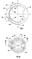
- Fig. 2 is a perspective view of the transducer.
- Transducer 100 is shown contained within a pulley 200.
- a bearing or bearings 205 are pressed onto the outside of outer ring 103 to occupy an annular space between outer ring 103 and pulley 200.
- Bracket 500 is attached to transducer 100 with fasteners 501, 502.
- Pulley 200 may have any belt bearing profile known in the art.
- Fig. 3 is a plan view of the transducer sensor ring.
- Sensor ring 102 is shown with strain gages 301, 302, 303, 304 mounted thereto in a full bridge configuration.
- the strain gages are connected by wires 401, 402, 403, 404. Wires 402 and 403 are routed to bracket 500 for connection to an instrument lead wire.
- Strain gages 301 and 304 may be attached to sensor ring 102 through apertures 105 and 106.
- Strain gages 302 and 303 are mounted to sensor ring 102 through apertures 120, 121.
- the strain gages are oriented so that a force vector axis A-A is perpendicular to an imaginary line B-B between the strain gages.
- the strain gage full bridge configuration is substantially as described in Fig. 12 and Fig. 14 .
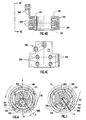
- Fig. 4A is a plan view of the hubload transducer. This is the embodiment using a separate hub ring 101, sensor ring 102 and outer ring 103 as described elsewhere herein.
- Sensor ring 102 is fastened to outer ring 103 using screws 203 and 204.
- Hub ring 101 is fastened to sensor ring 102 using screws 201 and 202.
- Other means of fastening the rings may comprise welding, adhesives, riveting, or other appropriate means known in the art.
- Screws 201, 202, 203, 204 are oriented as shown with respect to a hubload axis A-A.
- Fig. 4B is a cross-sectional view of Fig. 4A at line 4B-4B. Screws 201 and 204 are shown connecting sensor ring 102 to outer ring 103. Bracket 500 provides a means to connect the strain gage wires to an instrument lead wire as described elsewhere herein.
- Fig. 4C is a side view at 4C-4C in Fig. 4B . Screws 203 and 204 are shown connecting outer ring 103 to sensor ring 102 .
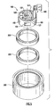
- Fig. 5 is a perspective exploded view of the transducer.
- Bearings 205 are pressed on outer ring 103 of transducer 100.
- Pulley 200 is pressed onto bearings 205.
- Apertures 120 and 121 provide access for mounting strain gages on sensor ring 102.
- Fig. 6 is a partial plan view of the self-aligning portion.
- the sensor ring be disposed to the hubload vector 600 such that vector 600 aligns with axis A-A, thereby aligning the strain gages with an axis B-B, see Fig. 3 . This can be accomplished using a self-aligning member 700.
- an eccentric self-aligning member 700 is disposed in inner ring bore 104.
- eccentric member 700 is press fit into bore 104.
- member 700 may also simply comprise an integral part of arcuate inner member 101, namely, arcuate inner member comprises a bore 701 having a center 705 which is not aligned with a transducer geometric center.
- Eccentric member 700 comprises a bore 701. Center 705 of bore 701 is eccentrically disposed a distance from an eccentric member geometric center 704. Eccentric member geometric center 704 also coincides with a transducer geometric center and sensor ring geometric center. Bearing 702 is pressed into bore 701. A fastening member 703, such as a bolt, projects through and attaches bearing 702, and thereby the transducer, to a mounting surface (not shown). By action of bearing 702 the transducer is freely rotatable about fastening member 703.
- a hubload vector 600 acting upon the transducer.
- the hubload is caused by a belt BT having a tension.
- vector 600 is initially laterally offset from bore center 705 by a distance (D).
- distance (D) acts as a lever arm which causes a torque to be applied to eccentric member 700.
- the torque causes eccentric member 700, and thereby transducer 100 and sensor ring 102, to rotate about bearing 702 until vector 600 aligns with center 705, thereby eliminating the self-aligning torque and restoring equilibrium. This manner of operation of self-alignment applies regardless of the direction of vector 600.
- Fig. 7 is a partial plan view of the self-aligning portion.
- Vector 600 is aligned with bore center 705. This orientation results in strain gages 301, 302, 303, 304 being in an optimum sensing position, that is, aligned with axis B-B as described in Fig. 3 .
- the transducer can operate with or without the self-aligning member 700 as described in Figs. 6 and 7 .
- Use of the self-aligning member 700 depends upon a desired sensitivity and operating condition for the transducer. This may also depend in part upon a range of movement of vector 600 during operation.
- the sensitivity of the transducer is a function of the alignment of the strain gage(s) with a load vector 600. For example, if the inventive transducer is used with an idler with a narrow range of directions for vector 600, the need for the self-aligning member may be less important.
- use of the self-aligning member is advantageous to maintain a desired sensitivity for the transducer.
- Fig. 8 is a schematic view of a belt accessory drive.
- the drive described herein uses both the multiple-ribbed side and backside of the belt (B). This eliminates the need for multiple belts which otherwise would be needed to drive each accessory component, which in turn reduces the overall front to back engine dimension.
- a typical arrangement of a belt drive is shown in Figure 8 .
- the pulley's are marked: alternator "AL”, power assisted steering pump “PA”, non-torque, no torque load transmitting tensioner idler “IDL”, water pump “WP”, crankshaft “CR”, and air conditioner compressor “AC”.
- Each of the belt spans between the pulleys are marked: PA to IDL “1” , IDL to WP “2”, WP to CR “3”, CR to AC “4", AC to AL “5", AL to PA “6”.
- a hubload transducer is mounted at the tensioner IDL.
- a torque transducer is mounted at AC, AL, PA and WP. Torques are transmitted at each accessory and CR.
- Operating belt tension dynamic measurement means that the measurement is performed while the engine and belt is in operation. This as opposed to the so-called belt tension static measurement which is undertaken while the engine and belt are not in operation.
- a span vibration frequency measurement technique known in the art, can be used to estimate the tension at each belt span by exciting an oscillation in each belt span.
- the hubload transducer as described in Figs. 1-7 herein, is installed at the idler (IDL) pulley. No load (torque) is transmitted at the idler (IDL) pulley.
- a typical single serpentine belt accessory drive system will have at least one idler pulley for either belt routing or belt tension control.
- the idler pulley is mounted on a tensioner, it is called “automatic tension control”.
- the idler pulley is mounted on a jackscrew assembly, it is called "fixed center tension control”.
- the hubload force measured by the transducer, H is referred as the "baseline tension measurement". As described for Figs.
- the strain gages on the hubload transducer generate a signal which is fed to instruments known in the art, for example a signal conditioner/amplifier and oscilloscope or digital meter, which displays the hubload force in newtons.
- a signal conditioner/amplifier and oscilloscope or digital meter which displays the hubload force in newtons.
- An exemplary strain gage signal conditioner/amplifier is an IO Tech strain gage module DBK43A TM 8-channel strain gage module displayed on the web at URL http://www.iotech.com/catalog/dag/catdbk43.html .
- the torque transducer can transmit and measure a torque.
- the torque transducer to connected to a multiple-ribbed pulley for the maximum friction capacity.
- the torque value measured by the torque transducer is referred as the "incremental tension measurement".
- Torques Q CR , Q AC , Q AL , Q PA ,and Q WP are directly measured with torque transducers at each corresponding shaft. Rotational speed, in RPM, is measured at each corresponding shaft as well. Due to the relatively high efficiency of the subject belt pulley system, the quasi-energy conservation state can be closely achieved. Therefore, the total number of required torque transducers can be the total number of torque components minus one.
- driver torque and driven torque will be denoted by “+” and "-” respectively when using equations (2) and (3).
- driver torque is a crankshaft damper torque
- driven torque is the particular components' torque, for example, air conditioner compressor, alternator, and so on.
- the crankshaft torque is calculated using equation (3).
- the baseline tension at span 1 and span 2 is calculated using baseline tension equation (1).
- Adjacent span tensions, e.g., spans 3 through 6 are calculated using torque transducer measurements using the incremental tension equation (2).
- Fig. 9 is a cross-sectional view of a torque transducer.
- Torque sensor 1000 is shown connected to a shaft 1001.
- Shaft 1001 is a rotating shaft for power (torque) input to a driven accessory such as AC, AL, WP, PA, or power output (torque) from a driver such as a crankshaft CRK.
- Sensor 1000 comprises ring 1002 which is used to fasten the transducer to shaft 1001 using threaded fasteners 1003.
- Ring 1002 is also fastened to strainable cylindrical body 1005.
- Strainable cylindrical body 1005 is in turn fastened to belt engaging ring 1007.
- Belt engaging ring 1007 also comprises belt engaging portion 1008.
- Portion 1008 is shown with a multiple-ribbed profile.
- Portion 1008 can also comprise a flat or single groove (v-belt) profile depending upon the belt used in the belt drive system.
- Strainable cylindrical body 1005 is sufficiently thin so as to be torsionally strainable when subjected to an operational torque load.
- Body 1005 may comprise any material with sufficient strength and toughness to survive the torque transmitting service while being sufficiently flexible to strain without failing when under operational loads.
- Acceptable materials include plastic as well as metallic materials, including aluminum, steel, titanium, magnesium, and alloys and combinations thereof. The materials are selected based on the operational requirements of the system.
- ring 1002, ring 1007 and portion 1008 are each sufficiently rigid as compared to body 1005 so that substantially all of the strains in ring 1002, ring 1007 and portion 1008 are insignificantly small as compared to the strain in cylindrical body 1005. It is desirable that substantially all strain in the torque transducer be manifest in cylindrical body 1005. This maximizes the strain to be detected by the strain gages thereby maximizing the resistance change in the strain gages, which in turn optimizes the voltage change as detected by attached instrumentation.
- a low friction bearing 1009 is disposed between ring 1007 and portion 1008 and cylindrical body 1005.
- Bearing 1009 simultaneously radially supports ring 1007 and portion 1008 while preventing ring 1007 from becoming torsionally fixed with respect to ring 1002, thereby confining all torque to be transmitted through cylindrical body 1005.
- Bearing 1009 may comprise any suitable low friction bearing known in the art, including but not limited to ball, needle, and roller bearings. Lubricated, low friction sliding surfaces may also be used in lieu of bearings.
- Fig. 10 is a cross-sectional view of an alternate embodiment of the torque transducer.
- a signal conditioner 2002 and slip ring 2001 used in the inventive torque transducer are known in the art, for example, a one piece unit provided by Michigan Scientific, Inc., part no. Short S6/X/SG1.
- the slip ring 2001 is shown cooperating with adapter 2012.
- Component shaft 2006 is connected to adapter 2012 using key 2015.
- Adapter 2012 is connected to strainable cylindrical body 2009 by fasteners 2011.
- Bearings 2003 and 2004 support the belt bearing surface 2005 at each end while allowing strains to be isolated in the cylindrical body 2009.
- Adapter plate 2010 connects slip ring/signal conditioner to the cylindrical body 2009 using fasteners 2016.
- the strain gage configuration adhered to a surface of cylindrical strainable body 2009 may comprise any of those depicted in Figs. 12 thru 15 .
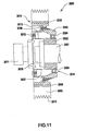
- Fig. 11 is a cross-sectional view of an alternate embodiment of the torque transducer.
- Hub 3002 is connected to crankshaft 3001 using bolt 3005.
- Crankshaft 3001 is part of an automotive engine (not shown).
- Hub 3002 comprises strainable cylindrical or tubular portion 3006. Strain gages are attached to tubular portion surface 3007 as described in Figs. 12-15 herein.
- Strainable tubular portion 3006 is connected to outer ring 3003 by bolts 3013.
- a known slip ring and signal conditioner 3011 is connected to tubular portion 3006 by bolts 3012.
- Portion 3006 and outer ring 3003 may also be machined or manufactured as a single unit thereby eliminating the need for bolts 3012 and 3013 and thereby reducing an overall component weight.
- a bearing 3004 is disposed between outer ring 3003 and hub 3002 in annular space 3015. Annular space 3015 and bearing 3004 are radially disposed from crankshaft 3001 to optimize a torsional strain on tubular portion 3006. When subjected to a torque bearing 3004 allows outer ring 3003 to rotate slightly with respect to hub 3002, thereby straining tubular portion 3006 in proportion to the applied torque. A sufficiently high modulus for outer ring 3003 assures that all torque related strains are substantially isolated to tubular portion 3006. Bearing 3004 supports tubular portion 3006 to prevent it from unduly deforming or twisting under load. Bearing 3004 comprises a sealed ball bearing. In the case where tubular portion 3006 and outer ring 3003 comprise a single unit, bearing 3004 is installed by a press fit.
- Elastomeric member 3008 is disposed between outer ring 3003 and belt bearing member 3009.
- Elastomeric member 3008 may comprise any natural rubber or synthetic rubber or any combination thereof, including but not limited to HNBR and or EPDM.
- Member 3008 is retained between member 3009 and outer ring 3003 by adhesives known in the art or by being compressed in the annular space 3014, or by a combination thereof. Compression of elastomeric member 3008 is in the range of 20% to 70% of an uncompressed thickness.
- Elastomeric member 3008 damps crankshaft vibrations caused by rotation of the crankshaft and operation of the engine. Damping vibrations in this manner reduces wear on the belt drive system driven by the crankshaft, thereby increasing a useful life of the system components and reducing transmission of undesirable noise and vibration to a vehicle frame and occupant.
- Belt bearing member 3009 has a multiple-ribbed profile 3010 for engaging a multiple-ribbed belt.
- An integrated slip ring and signal conditioner 3011 of the type described in Fig. 10 is connected to hub 3002 with bolts 3012.
- the torque transducer is sufficiently compact so it is useable in the same size volume as currently required by a crankshaft damper.
- Fig. 12 is a schematic diagram of a single full bridge strain gage installation as disposed on a strainable member.
- Cylindrical body 1005 is shown "unrolled" in plan view with cylindrical positions marked as 0° and 180°.
- An axis of rotation is R-R.
- a 45° strain gage pair T1C1 and T2C2 are shown at positions 0° and 180° on an outwardly disposed surface of body 1005.
- the term "45°” refers to the angular relationship of each strain gage major axial direction to axis A-A.
- Axis A-A is disposed at an angle of 90 degrees to axis R-R.
- the angular relationship affords maximum sensitivity for detecting a torsional strain since the strain gage axis is substantially aligned with a predominant strain direction.
- the angle may be in the range of approximately 40°-50° with acceptable result.
- the depictions in Figs. 12-15 are also representative of the strain gage configuration on tubular portion 3006.
- Fig. 13 is a schematic diagram of a single full bridge strain gage installation with bipolar excitation.
- Strain gages T1, T2, C1, C2 each comprise known resistances suitable for the service.
- Each is bonded to the surface of the cylindrical body 1005 as shown in Fig. 11 . Deformation of body 1005 is proportional to the torque transmitted by the pulley/sensor combination.
- the signal to the strain gage signal conditioner and connected instrumentation module is denoted S+ and S-.
- the voltage source is denoted P+ and P-.
- Fig. 14 is a schematic diagram of a double bridge strain gage installation disposed on a strainable member.
- Cylindrical body 1005 is shown "unrolled" in plan view with cylindrical positions marked as 0°, 90°, 180°, and 270° on an outwardly disposed surface of body 1005.
- 45° strain gage pairs are disposed as follows: T1C1 at 0°, T2C2 at 90°, T3C3 at 180°, and T4C4 at 270°.
- Strain gages T1, T2, T3, T4, C1, C2, C3, C4 each comprise known resistances suitable for the service.
- Each strain gage is bonded to the surface of the cylindrical body 1005 as shown in Fig.
- the term "45°” refers to the angular relationship of each strain gage major axial direction to axis A-A.
- Axis A-A is disposed at an angle of 90 degrees to axis R-R. This affords maximum sensitivity for detecting a torsional strain since the strain gage axis is substantially aligned with a predominant strain direction.
- the angle may be in the range of approximately 40°-50° with acceptable result.
- Fig. 15 is a schematic diagram of a double bridge strain gage installation with bipolar excitation.
- the double bridge strain gage affords increased sensitivity for detecting small strains.
- the signal to the strain gage signal conditioner and instrumentation module is denoted S+ and S-.
- the voltage source is denoted P+ and P-.
- the system and components can be used in existing vehicle front-end accessory drives with a minimum of modification.
- the hubload transducer fits within an idler pulley.
- the torque transducers offer great flexibility as each can be either installed as original equipment or retrofitted to existing torque transmitting accessory pulleys and crankshaft.
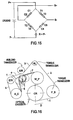
- Fig. 16 is a schematic of a test belt drive system.
- a torque transducer is installed at the P_S, power steering, and ALT, alternator pulley.
- a hubload transducer is installed at the idler (IDL) pulley.
- the belt is driven in direction D by crankshaft pulley CRK.
- a user may instrument (n-1) pulleys using a hubload transducer and torque transducers where (n) is the total number of pulleys.
- Layout data for the test system in Fig. 16 is as follows: Layout Data [mm] Layout # 1 X Coordinate Y Coordinate Flat Diameter Pitch Diameter Effective Diameter CRK n nn n nn 170.31 168.31 P_S 191.20 19.80 139.97 137.97 AL1 -7.00 335.00 53.31 51.31 IDR -158.00 253.50 76.00 78.40 80.40 IDR -266.60 139.25 78.71 76.71 A_C -707.10 -7.40 116.01 114.01 TEN -144.96 160.56 76.00 78.40 80.40 W_P 22.00 172.00 129.00 131.40 133.40 Belt Drive System Geometry Span Length [mm] Wrap Angle Acceler.
- the rotational speed needs to be measured as well in order to determine this quantity.
- the torque at crankshaft should be measured directly using the torque transducer instead of being calculated:
- ⁇ 95.19 %
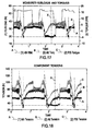
- Fig. 17 is a graph showing measured hubload and torques for the test belt drive system.
- the sample belt span tension calculations performed above are taken at time step 23 seconds. Although torques T 1 , T 2 , T 3 , and T 4 can be calculated at each time step, time step 23 is chosen randomly.
- Curve (A) is the idler hubload.
- Curve (B) is the alternator torque and curve (C) is the power steering pump (P/S) torque.
- P/S power steering pump
- the test system is subjected to three load/unload cycles. From time 0 to approximately time 4 seconds, the alternator torque and idler hubload are substantially constant. At approximately time 2 seconds the power steering torque increases, corresponding to an increase in load. The load holds substantially constant to approximately time 11 seconds. From approximately time 4 seconds to time 5 seconds the alternator torque decreases. At time 5 seconds the alternator torque steadily increases through time 9 seconds, where it levels off. At approximately time 4 seconds the hubload decreases through time 6 seconds. At time 6 seconds it abruptly increases to the value measured at time 4 seconds. At time 11 seconds the cycle repeats through time 25 seconds, and repeats yet again through time 37+ seconds.
- Fig. 18 is a graph of the calculated tensions at each time step for the test belt drive system.
- Cursor X is placed at the 23 second mark to correlate and illustrate results from Fig. 16 .
- Curve (A) is the idler tension, T 4 .
- Curve (B) is the alternator tension, T 3 , and curve (C) is the power steering pump (P/S) tension, T 2 .
- the calculations described herein are preferably performed using a computer programmed to perform the calculations. The computer programming is accomplished using known methods.
- Fig. 18 The progression of each of the cycles described in Fig. 17 is clearly observed in Fig. 18 .
- the idler belt span tension in span 3 and span 4 as shown in Fig. 16 corresponds to the idler hubload shown in Fig. 17 .
- the belt tension in span 2 (curve (B)) is a function of the alternator torque, see Fig. 17 .
- the belt tension in span 1 (curve (C)) is a function of the alternator torque and the power steering torque, see Fig. 17 .
Landscapes
- Physics & Mathematics (AREA)
- General Physics & Mathematics (AREA)
- Force Measurement Appropriate To Specific Purposes (AREA)
- Devices For Conveying Motion By Means Of Endless Flexible Members (AREA)
- Measurement Of Force In General (AREA)
Priority Applications (1)
| Application Number | Priority Date | Filing Date | Title |
|---|---|---|---|
| EP08075773A EP2026055A1 (en) | 2003-06-04 | 2004-05-26 | Apparatus and method of belt dynamic tension measurement |
Applications Claiming Priority (2)
| Application Number | Priority Date | Filing Date | Title |
|---|---|---|---|
| US10/454,989 US20040244504A1 (en) | 2003-06-04 | 2003-06-04 | Apparatus and method of belt dynamic tension measurement |
| PCT/US2004/016474 WO2004109247A2 (en) | 2003-06-04 | 2004-05-26 | Apparatus and method of belt dynamic tension measurement |
Related Child Applications (1)
| Application Number | Title | Priority Date | Filing Date |
|---|---|---|---|
| EP08075773A Division EP2026055A1 (en) | 2003-06-04 | 2004-05-26 | Apparatus and method of belt dynamic tension measurement |
Publications (2)
| Publication Number | Publication Date |
|---|---|
| EP1629261A2 EP1629261A2 (en) | 2006-03-01 |
| EP1629261B1 true EP1629261B1 (en) | 2008-10-01 |
Family
ID=33489835
Family Applications (2)
| Application Number | Title | Priority Date | Filing Date |
|---|---|---|---|
| EP04753319A Expired - Lifetime EP1629261B1 (en) | 2003-06-04 | 2004-05-26 | Apparatus and method of belt dynamic tension measurement |
| EP08075773A Withdrawn EP2026055A1 (en) | 2003-06-04 | 2004-05-26 | Apparatus and method of belt dynamic tension measurement |
Family Applications After (1)
| Application Number | Title | Priority Date | Filing Date |
|---|---|---|---|
| EP08075773A Withdrawn EP2026055A1 (en) | 2003-06-04 | 2004-05-26 | Apparatus and method of belt dynamic tension measurement |
Country Status (13)
| Country | Link |
|---|---|
| US (2) | US20040244504A1 (ja) |
| EP (2) | EP1629261B1 (ja) |
| JP (1) | JP4242423B2 (ja) |
| KR (2) | KR100903836B1 (ja) |
| CN (1) | CN100453990C (ja) |
| AT (1) | ATE409853T1 (ja) |
| AU (1) | AU2004245934B2 (ja) |
| BR (1) | BRPI0410898A (ja) |
| DE (1) | DE602004016843D1 (ja) |
| ES (1) | ES2313041T3 (ja) |
| PL (1) | PL379620A1 (ja) |
| TW (1) | TWI258576B (ja) |
| WO (1) | WO2004109247A2 (ja) |
Families Citing this family (39)
| Publication number | Priority date | Publication date | Assignee | Title |
|---|---|---|---|---|
| JP4656995B2 (ja) * | 2005-04-21 | 2011-03-23 | 本田技研工業株式会社 | 回転体装置 |
| US7771302B2 (en) | 2005-04-21 | 2010-08-10 | Dayco Products, Llc | Apparatus for indicating power transmission belt dynamics |
| US7678002B2 (en) | 2006-08-31 | 2010-03-16 | Dayco Products, Llc | One-way clutched damper for automatic belt tensioner |
| US8038555B2 (en) | 2006-08-31 | 2011-10-18 | Dayco Products, Llc | One-way clutched damper for automatic belt tensioner |
| US8162787B2 (en) | 2006-08-31 | 2012-04-24 | Dayco Products, Llc | One-way clutched damper for automatic belt tensioner |
| EP1923684B1 (de) * | 2006-11-20 | 2011-02-16 | Texmag GmbH Vertriebsgesellschaft | Vorrichtung zum Messen einer Zugkraft innerhalb einer Materialbahn oder eines Materialstranges |
| EP1932791B1 (de) * | 2006-12-15 | 2009-09-09 | Texmag GmbH Vertriebsgesellschaft | Verfahren zur Messung der Zugspannung einer laufenden Bahn |
| KR20100102610A (ko) * | 2007-11-13 | 2010-09-24 | 지아이에프 게젤샤프트 퓌어 인더스트리포르슝 엠베하 | 토크 측정 장치, 토크 측정 플랜지 및 토크 측정 방법 |
| US7931552B2 (en) | 2008-04-30 | 2011-04-26 | Dayco Products, Llc | Pulley with torque-sensitive clutching |
| US8529387B2 (en) | 2008-04-30 | 2013-09-10 | Dayco Ip Holdings, Llc | Pulley with asymmetric torque-sensitive clutching |
| JP2010025574A (ja) * | 2008-07-15 | 2010-02-04 | B L Auto Tec Kk | 起歪体 |
| US8403785B2 (en) | 2008-11-05 | 2013-03-26 | Dayco Ip Holdings, Llc | Clutched damper for a belt tensioner |
| WO2010129699A2 (en) * | 2009-05-05 | 2010-11-11 | Valley Forge & Bolt Manufacturing Co. | Monitoring fastening loading |
| US8888627B2 (en) | 2010-05-25 | 2014-11-18 | Dayco Ip Holdings, Llc | One-way damped over-arm tensioner |
| DE102010024617B4 (de) * | 2010-06-22 | 2014-12-18 | Texmag Gmbh Vertriebsgesellschaft | Vorrichtung zum Messen einer Zugkraft innerhalb einer Materilbahn oder eines Materialstrangs |
| US8439781B2 (en) | 2010-06-22 | 2013-05-14 | Dayco Ip Holdings, Llc | Radial damping mechanism and use for belt tensioning |
| US8604776B2 (en) * | 2010-06-24 | 2013-12-10 | Schrader Electronics Ltd. | Power transmission monitoring and maintenance systems and methods |
| US20120179392A1 (en) * | 2011-01-11 | 2012-07-12 | Bridgestone Americas Tire Operations, Llc | Method and system for measuring strain in twisted cord |
| AU2012352309A1 (en) * | 2011-12-16 | 2014-06-12 | Dayco Ip Holdings, Llc | Pulley assembly with a decoupling mechanism |
| ITTO20130677A1 (it) | 2013-08-06 | 2015-02-07 | Dayco Europe Srl | Puleggia filtrante per una trasmissione a cinghia |
| US9068878B2 (en) * | 2013-08-23 | 2015-06-30 | Trimble Navigation Limited | Vehicle weight sensor based on wheel rim strain measurements |
| US9291217B2 (en) | 2014-04-08 | 2016-03-22 | Dayco Ip Holdings, Llc | Pulley assembly with radially oriented decoupling mechanism |
| CN104458094B (zh) * | 2014-12-22 | 2017-02-22 | 无锡永凯达齿轮有限公司 | 汽车发动机皮带动态张力的采集单元 |
| TWI549666B (zh) * | 2015-01-05 | 2016-09-21 | 國立清華大學 | 具有測量僵硬程度的功能之復健系統 |
| CN104806733B (zh) * | 2015-03-20 | 2017-07-28 | 同济大学 | 一种基于轴承受力的转矩检测结构和方法 |
| JP6092326B2 (ja) * | 2015-07-29 | 2017-03-08 | 株式会社トライフォース・マネジメント | トルクセンサ |
| CN105445122B (zh) * | 2015-11-03 | 2018-01-02 | 江铃控股有限公司 | 汽车发动机曲轴皮带轮紧固工艺测量系统 |
| WO2017130448A1 (ja) * | 2016-01-25 | 2017-08-03 | 三菱電機株式会社 | 荷重検出器 |
| JP6780663B2 (ja) | 2016-02-10 | 2020-11-04 | 株式会社リコー | 情報表示装置 |
| DE102016013890A1 (de) * | 2016-11-21 | 2018-05-24 | Rheinisch-Westfälische Technische Hochschule (Rwth) Aachen | Verfahren zur Bestimmung der Achslast auf Linear- und Rundachsen |
| CN107421665A (zh) * | 2017-06-29 | 2017-12-01 | 太仓市荣驰电机有限公司 | 一种压力测量装置 |
| CN110998268B (zh) * | 2017-07-26 | 2021-06-29 | 三菱电机株式会社 | 载荷检测器 |
| US11345043B2 (en) * | 2018-07-02 | 2022-05-31 | Flexiv Ltd. | Axial force sensor, robot gripper, and robot having the same |
| CN109187010B (zh) * | 2018-07-12 | 2020-10-30 | 四川大学 | 一种带传动系统动态性能测试装置 |
| CN109115487B (zh) * | 2018-07-12 | 2020-09-25 | 四川大学 | 带传动系统动态性能测试工作电路和工作方法 |
| CA3118131A1 (en) * | 2018-10-30 | 2020-05-07 | Superior Industries, Inc. | Conveyor idler monitoring apparatus, systems, and methods |
| US10962100B2 (en) * | 2019-07-24 | 2021-03-30 | Denso International .America, Inc. | Engine pulley movement detection |
| CN112699501B (zh) * | 2020-12-02 | 2024-04-26 | 中国船舶科学研究中心 | 一种基于滑轮轴的缆索拉力监测系统 |
| DE102022203808A1 (de) * | 2022-04-14 | 2023-10-19 | Contitech Antriebssysteme Gmbh | Riemenbetriebene Verstelleinrichtung |
Family Cites Families (29)
| Publication number | Priority date | Publication date | Assignee | Title |
|---|---|---|---|---|
| US3705530A (en) * | 1970-12-14 | 1972-12-12 | Collins Radio Co | Force hub sensor for control wheel steering |
| JPS5525370B2 (ja) * | 1972-03-03 | 1980-07-05 | ||
| FR2278068A1 (fr) * | 1974-07-12 | 1976-02-06 | Simon Francois | Dispositif de mesure de l'effort radial supporte par un organe rotatif |
| CH631013A5 (de) * | 1978-09-20 | 1982-07-15 | Schmid Roost J Sro Kugellagerw | Messvorrichtung. |
| US4326424A (en) * | 1979-03-30 | 1982-04-27 | Cleveland Machine Controls, Inc. | Web tension transducer arrangement |
| GB2109568A (en) * | 1981-11-06 | 1983-06-02 | Exxon Research Engineering Co | Measuring torque on a vehicle wheel |
| DE3336727C2 (de) * | 1983-10-08 | 1985-09-12 | Erhardt & Leimer GmbH, 8900 Augsburg | Vorrichtung zur Linearkraftmessung |
| US4731044A (en) * | 1985-12-18 | 1988-03-15 | Borg-Warner Automotive, Inc. | Tension sensor and control arrangement for a continuously variable transmission |
| DE3603187A1 (de) * | 1986-02-03 | 1987-08-06 | Erhardt & Leimer Gmbh | Vorrichtung zur linearkraftmessung |
| US4735102A (en) * | 1986-03-07 | 1988-04-05 | Cleveland Machine Controls, Inc. | Web tension transducer apparatus |
| US4691579A (en) * | 1986-06-03 | 1987-09-08 | Ekola Kenneth E | Tension transducer |
| US4821583A (en) * | 1987-07-14 | 1989-04-18 | E. I. Du Pont De Nemours And Company | Tension measuring apparatus |
| US4784004A (en) * | 1987-08-20 | 1988-11-15 | Ekola Kenneth E | Web tension transducer |
| US4796474A (en) * | 1987-09-02 | 1989-01-10 | Cleveland Machine Controls, Inc. | Web tension transducer apparatus |
| CN87213769U (zh) * | 1987-09-29 | 1988-08-03 | 东北重型机械学院 | 装卡式扭矩传感器 |
| US4899599A (en) * | 1987-12-07 | 1990-02-13 | Magnetic Power Systems, Inc. | Strain force sensor means |
| US5113709A (en) * | 1990-05-29 | 1992-05-19 | Ekola Kenneth E | Convertible web tension transducer |
| CN2228225Y (zh) * | 1994-11-02 | 1996-05-29 | 印广力 | 传动轴扭矩传感器 |
| JPH0996693A (ja) * | 1995-09-29 | 1997-04-08 | Toshiba Corp | 制御棒駆動機構 |
| JP3163046B2 (ja) * | 1996-10-25 | 2001-05-08 | 三洋電機株式会社 | 補助動力付人力走行車 |
| CA2311673C (en) * | 1997-11-26 | 2009-02-17 | Litens Automotive Partnership | Load sensor having an annular gauge ring |
| US6324919B1 (en) * | 1998-02-04 | 2001-12-04 | Michigan Scientific Corporation | Multi-axis wheel load transducer |
| JP2001099271A (ja) * | 1999-09-30 | 2001-04-10 | Mitsuboshi Belting Ltd | ベルト荷重測定用プーリ |
| JP2001132634A (ja) | 1999-11-01 | 2001-05-18 | Toyota Autom Loom Works Ltd | 容量可変型圧縮機 |
| CN2408448Y (zh) * | 1999-12-03 | 2000-11-29 | 跃进汽车集团公司 | 车轮扭矩传感器 |
| DE19960786A1 (de) * | 1999-12-16 | 2001-06-21 | Schenck Process Gmbh | Radialkraftaufnehmer |
| US6360616B1 (en) * | 2000-10-13 | 2002-03-26 | Donald R. Halliday | Automated diagnosis and monitoring system, equipment, and method |
| US6834228B2 (en) | 2001-10-25 | 2004-12-21 | The Gates Corporation | Belt drive system with automatic belt tension control |
| US7021159B2 (en) * | 2002-09-30 | 2006-04-04 | The Gates Corporation | Transducer |
-
2003
- 2003-06-04 US US10/454,989 patent/US20040244504A1/en not_active Abandoned
-
2004
- 2004-05-26 AT AT04753319T patent/ATE409853T1/de not_active IP Right Cessation
- 2004-05-26 AU AU2004245934A patent/AU2004245934B2/en not_active Ceased
- 2004-05-26 CN CNB2004800154184A patent/CN100453990C/zh not_active Expired - Fee Related
- 2004-05-26 WO PCT/US2004/016474 patent/WO2004109247A2/en active Application Filing
- 2004-05-26 ES ES04753319T patent/ES2313041T3/es not_active Expired - Lifetime
- 2004-05-26 EP EP04753319A patent/EP1629261B1/en not_active Expired - Lifetime
- 2004-05-26 KR KR1020077023651A patent/KR100903836B1/ko not_active IP Right Cessation
- 2004-05-26 PL PL379620A patent/PL379620A1/pl unknown
- 2004-05-26 KR KR1020057023118A patent/KR100793673B1/ko not_active IP Right Cessation
- 2004-05-26 DE DE602004016843T patent/DE602004016843D1/de not_active Expired - Lifetime
- 2004-05-26 EP EP08075773A patent/EP2026055A1/en not_active Withdrawn
- 2004-05-26 JP JP2006514956A patent/JP4242423B2/ja not_active Expired - Fee Related
- 2004-05-26 BR BRPI0410898-1A patent/BRPI0410898A/pt not_active IP Right Cessation
- 2004-06-02 TW TW093115737A patent/TWI258576B/zh not_active IP Right Cessation
- 2004-10-29 US US10/977,653 patent/US7055398B2/en not_active Expired - Fee Related
Non-Patent Citations (1)
| Title |
|---|
| None * |
Also Published As
| Publication number | Publication date |
|---|---|
| WO2004109247A2 (en) | 2004-12-16 |
| EP2026055A1 (en) | 2009-02-18 |
| WO2004109247B1 (en) | 2005-06-02 |
| WO2004109247A3 (en) | 2005-04-28 |
| JP4242423B2 (ja) | 2009-03-25 |
| EP1629261A2 (en) | 2006-03-01 |
| ATE409853T1 (de) | 2008-10-15 |
| DE602004016843D1 (de) | 2008-11-13 |
| TW200506330A (en) | 2005-02-16 |
| KR100793673B1 (ko) | 2008-01-10 |
| US7055398B2 (en) | 2006-06-06 |
| PL379620A1 (pl) | 2006-10-30 |
| TWI258576B (en) | 2006-07-21 |
| BRPI0410898A (pt) | 2006-07-04 |
| KR20070106593A (ko) | 2007-11-01 |
| KR20060017626A (ko) | 2006-02-24 |
| AU2004245934A1 (en) | 2004-12-16 |
| US20040244504A1 (en) | 2004-12-09 |
| US20050056100A1 (en) | 2005-03-17 |
| JP2006526782A (ja) | 2006-11-24 |
| CN100453990C (zh) | 2009-01-21 |
| AU2004245934B2 (en) | 2008-01-24 |
| CN1798962A (zh) | 2006-07-05 |
| KR100903836B1 (ko) | 2009-06-25 |
| ES2313041T3 (es) | 2009-03-01 |
Similar Documents
| Publication | Publication Date | Title |
|---|---|---|
| EP1629261B1 (en) | Apparatus and method of belt dynamic tension measurement | |
| EP0579722B1 (en) | Axially compact torque transducer | |
| RU2285903C2 (ru) | Измерительный преобразователь для измерения динамической характеристики вала | |
| KR102629855B1 (ko) | 토크 전달 샤프트에 인가되는 힘 및/또는 토크를 결정하기 위한 측정 장치 및 방법 | |
| EP1642105B1 (en) | Transmission system, and method for measuring a drive force therein | |
| JPH06109565A (ja) | モータのコギングトルク測定装置及び測定方法 | |
| US20220214238A1 (en) | Devices and methods for monitoring health and performance of a mechanical system |
Legal Events
| Date | Code | Title | Description |
|---|---|---|---|
| PUAI | Public reference made under article 153(3) epc to a published international application that has entered the european phase |
Free format text: ORIGINAL CODE: 0009012 |
|
| 17P | Request for examination filed |
Effective date: 20051118 |
|
| AK | Designated contracting states |
Kind code of ref document: A2 Designated state(s): AT BE BG CH CY CZ DE DK EE ES FI FR GB GR HU IE IT LI LU MC NL PL PT RO SE SI SK TR |
|
| DAX | Request for extension of the european patent (deleted) | ||
| RIC1 | Information provided on ipc code assigned before grant |
Ipc: G01L 5/10 20060101AFI20070116BHEP |
|
| RIN1 | Information on inventor provided before grant (corrected) |
Inventor name: ALI, IMTIAZ Inventor name: MUSYJ, JOEL, PATRICK Inventor name: YUAN, JING |
|
| GRAP | Despatch of communication of intention to grant a patent |
Free format text: ORIGINAL CODE: EPIDOSNIGR1 |
|
| GRAS | Grant fee paid |
Free format text: ORIGINAL CODE: EPIDOSNIGR3 |
|
| GRAA | (expected) grant |
Free format text: ORIGINAL CODE: 0009210 |
|
| AK | Designated contracting states |
Kind code of ref document: B1 Designated state(s): AT BE BG CH CY CZ DE DK EE ES FI FR GB GR HU IE IT LI LU MC NL PL PT RO SE SI SK TR |
|
| REG | Reference to a national code |
Ref country code: GB Ref legal event code: FG4D |
|
| REG | Reference to a national code |
Ref country code: CH Ref legal event code: EP |
|
| REG | Reference to a national code |
Ref country code: IE Ref legal event code: FG4D |
|
| REF | Corresponds to: |
Ref document number: 602004016843 Country of ref document: DE Date of ref document: 20081113 Kind code of ref document: P |
|
| PG25 | Lapsed in a contracting state [announced via postgrant information from national office to epo] |
Ref country code: SI Free format text: LAPSE BECAUSE OF FAILURE TO SUBMIT A TRANSLATION OF THE DESCRIPTION OR TO PAY THE FEE WITHIN THE PRESCRIBED TIME-LIMIT Effective date: 20081001 |
|
| REG | Reference to a national code |
Ref country code: ES Ref legal event code: FG2A Ref document number: 2313041 Country of ref document: ES Kind code of ref document: T3 |
|
| NLV1 | Nl: lapsed or annulled due to failure to fulfill the requirements of art. 29p and 29m of the patents act | ||
| PG25 | Lapsed in a contracting state [announced via postgrant information from national office to epo] |
Ref country code: AT Free format text: LAPSE BECAUSE OF FAILURE TO SUBMIT A TRANSLATION OF THE DESCRIPTION OR TO PAY THE FEE WITHIN THE PRESCRIBED TIME-LIMIT Effective date: 20081001 Ref country code: BG Free format text: LAPSE BECAUSE OF FAILURE TO SUBMIT A TRANSLATION OF THE DESCRIPTION OR TO PAY THE FEE WITHIN THE PRESCRIBED TIME-LIMIT Effective date: 20090101 |
|
| PG25 | Lapsed in a contracting state [announced via postgrant information from national office to epo] |
Ref country code: PT Free format text: LAPSE BECAUSE OF FAILURE TO SUBMIT A TRANSLATION OF THE DESCRIPTION OR TO PAY THE FEE WITHIN THE PRESCRIBED TIME-LIMIT Effective date: 20090302 Ref country code: PL Free format text: LAPSE BECAUSE OF FAILURE TO SUBMIT A TRANSLATION OF THE DESCRIPTION OR TO PAY THE FEE WITHIN THE PRESCRIBED TIME-LIMIT Effective date: 20081001 Ref country code: NL Free format text: LAPSE BECAUSE OF FAILURE TO SUBMIT A TRANSLATION OF THE DESCRIPTION OR TO PAY THE FEE WITHIN THE PRESCRIBED TIME-LIMIT Effective date: 20081001 Ref country code: FI Free format text: LAPSE BECAUSE OF FAILURE TO SUBMIT A TRANSLATION OF THE DESCRIPTION OR TO PAY THE FEE WITHIN THE PRESCRIBED TIME-LIMIT Effective date: 20081001 |
|
| PG25 | Lapsed in a contracting state [announced via postgrant information from national office to epo] |
Ref country code: RO Free format text: LAPSE BECAUSE OF FAILURE TO SUBMIT A TRANSLATION OF THE DESCRIPTION OR TO PAY THE FEE WITHIN THE PRESCRIBED TIME-LIMIT Effective date: 20081001 Ref country code: BE Free format text: LAPSE BECAUSE OF FAILURE TO SUBMIT A TRANSLATION OF THE DESCRIPTION OR TO PAY THE FEE WITHIN THE PRESCRIBED TIME-LIMIT Effective date: 20081001 Ref country code: EE Free format text: LAPSE BECAUSE OF FAILURE TO SUBMIT A TRANSLATION OF THE DESCRIPTION OR TO PAY THE FEE WITHIN THE PRESCRIBED TIME-LIMIT Effective date: 20081001 Ref country code: DK Free format text: LAPSE BECAUSE OF FAILURE TO SUBMIT A TRANSLATION OF THE DESCRIPTION OR TO PAY THE FEE WITHIN THE PRESCRIBED TIME-LIMIT Effective date: 20081001 |
|
| PLBE | No opposition filed within time limit |
Free format text: ORIGINAL CODE: 0009261 |
|
| STAA | Information on the status of an ep patent application or granted ep patent |
Free format text: STATUS: NO OPPOSITION FILED WITHIN TIME LIMIT |
|
| PG25 | Lapsed in a contracting state [announced via postgrant information from national office to epo] |
Ref country code: CZ Free format text: LAPSE BECAUSE OF FAILURE TO SUBMIT A TRANSLATION OF THE DESCRIPTION OR TO PAY THE FEE WITHIN THE PRESCRIBED TIME-LIMIT Effective date: 20081001 Ref country code: SE Free format text: LAPSE BECAUSE OF FAILURE TO SUBMIT A TRANSLATION OF THE DESCRIPTION OR TO PAY THE FEE WITHIN THE PRESCRIBED TIME-LIMIT Effective date: 20090101 |
|
| 26N | No opposition filed |
Effective date: 20090702 |
|
| PG25 | Lapsed in a contracting state [announced via postgrant information from national office to epo] |
Ref country code: SK Free format text: LAPSE BECAUSE OF FAILURE TO SUBMIT A TRANSLATION OF THE DESCRIPTION OR TO PAY THE FEE WITHIN THE PRESCRIBED TIME-LIMIT Effective date: 20081001 |
|
| PG25 | Lapsed in a contracting state [announced via postgrant information from national office to epo] |
Ref country code: MC Free format text: LAPSE BECAUSE OF NON-PAYMENT OF DUE FEES Effective date: 20090531 |
|
| REG | Reference to a national code |
Ref country code: CH Ref legal event code: PL |
|
| PG25 | Lapsed in a contracting state [announced via postgrant information from national office to epo] |
Ref country code: CH Free format text: LAPSE BECAUSE OF NON-PAYMENT OF DUE FEES Effective date: 20090531 Ref country code: LI Free format text: LAPSE BECAUSE OF NON-PAYMENT OF DUE FEES Effective date: 20090531 |
|
| REG | Reference to a national code |
Ref country code: IE Ref legal event code: MM4A |
|
| PG25 | Lapsed in a contracting state [announced via postgrant information from national office to epo] |
Ref country code: IE Free format text: LAPSE BECAUSE OF NON-PAYMENT OF DUE FEES Effective date: 20090526 |
|
| PGFP | Annual fee paid to national office [announced via postgrant information from national office to epo] |
Ref country code: ES Payment date: 20100526 Year of fee payment: 7 Ref country code: FR Payment date: 20100601 Year of fee payment: 7 |
|
| PGFP | Annual fee paid to national office [announced via postgrant information from national office to epo] |
Ref country code: DE Payment date: 20100527 Year of fee payment: 7 Ref country code: IT Payment date: 20100525 Year of fee payment: 7 |
|
| PG25 | Lapsed in a contracting state [announced via postgrant information from national office to epo] |
Ref country code: GR Free format text: LAPSE BECAUSE OF FAILURE TO SUBMIT A TRANSLATION OF THE DESCRIPTION OR TO PAY THE FEE WITHIN THE PRESCRIBED TIME-LIMIT Effective date: 20090102 |
|
| PGFP | Annual fee paid to national office [announced via postgrant information from national office to epo] |
Ref country code: GB Payment date: 20100525 Year of fee payment: 7 |
|
| PG25 | Lapsed in a contracting state [announced via postgrant information from national office to epo] |
Ref country code: LU Free format text: LAPSE BECAUSE OF NON-PAYMENT OF DUE FEES Effective date: 20090526 |
|
| PG25 | Lapsed in a contracting state [announced via postgrant information from national office to epo] |
Ref country code: HU Free format text: LAPSE BECAUSE OF FAILURE TO SUBMIT A TRANSLATION OF THE DESCRIPTION OR TO PAY THE FEE WITHIN THE PRESCRIBED TIME-LIMIT Effective date: 20090402 |
|
| PG25 | Lapsed in a contracting state [announced via postgrant information from national office to epo] |
Ref country code: TR Free format text: LAPSE BECAUSE OF FAILURE TO SUBMIT A TRANSLATION OF THE DESCRIPTION OR TO PAY THE FEE WITHIN THE PRESCRIBED TIME-LIMIT Effective date: 20081001 |
|
| PG25 | Lapsed in a contracting state [announced via postgrant information from national office to epo] |
Ref country code: CY Free format text: LAPSE BECAUSE OF FAILURE TO SUBMIT A TRANSLATION OF THE DESCRIPTION OR TO PAY THE FEE WITHIN THE PRESCRIBED TIME-LIMIT Effective date: 20081001 |
|
| GBPC | Gb: european patent ceased through non-payment of renewal fee |
Effective date: 20110526 |
|
| REG | Reference to a national code |
Ref country code: FR Ref legal event code: ST Effective date: 20120131 |
|
| PG25 | Lapsed in a contracting state [announced via postgrant information from national office to epo] |
Ref country code: IT Free format text: LAPSE BECAUSE OF NON-PAYMENT OF DUE FEES Effective date: 20110526 |
|
| REG | Reference to a national code |
Ref country code: DE Ref legal event code: R119 Ref document number: 602004016843 Country of ref document: DE Effective date: 20111201 |
|
| PG25 | Lapsed in a contracting state [announced via postgrant information from national office to epo] |
Ref country code: FR Free format text: LAPSE BECAUSE OF NON-PAYMENT OF DUE FEES Effective date: 20110531 |
|
| PG25 | Lapsed in a contracting state [announced via postgrant information from national office to epo] |
Ref country code: GB Free format text: LAPSE BECAUSE OF NON-PAYMENT OF DUE FEES Effective date: 20110526 |
|
| REG | Reference to a national code |
Ref country code: ES Ref legal event code: FD2A Effective date: 20130404 |
|
| PG25 | Lapsed in a contracting state [announced via postgrant information from national office to epo] |
Ref country code: ES Free format text: LAPSE BECAUSE OF NON-PAYMENT OF DUE FEES Effective date: 20110527 |
|
| PG25 | Lapsed in a contracting state [announced via postgrant information from national office to epo] |
Ref country code: DE Free format text: LAPSE BECAUSE OF NON-PAYMENT OF DUE FEES Effective date: 20111201 |