EP1628261B1 - Tomographic image reconstruction device and method - Google Patents
Tomographic image reconstruction device and method Download PDFInfo
- Publication number
- EP1628261B1 EP1628261B1 EP05255111A EP05255111A EP1628261B1 EP 1628261 B1 EP1628261 B1 EP 1628261B1 EP 05255111 A EP05255111 A EP 05255111A EP 05255111 A EP05255111 A EP 05255111A EP 1628261 B1 EP1628261 B1 EP 1628261B1
- Authority
- EP
- European Patent Office
- Prior art keywords
- image
- projection
- image processing
- data
- ray radiation
- Prior art date
- Legal status (The legal status is an assumption and is not a legal conclusion. Google has not performed a legal analysis and makes no representation as to the accuracy of the status listed.)
- Expired - Lifetime
Links
Images


Classifications
-
- G—PHYSICS
- G06—COMPUTING OR CALCULATING; COUNTING
- G06T—IMAGE DATA PROCESSING OR GENERATION, IN GENERAL
- G06T12/00—Tomographic reconstruction from projections
- G06T12/10—Image preprocessing, e.g. calibration, positioning of sources or scatter correction
-
- Y—GENERAL TAGGING OF NEW TECHNOLOGICAL DEVELOPMENTS; GENERAL TAGGING OF CROSS-SECTIONAL TECHNOLOGIES SPANNING OVER SEVERAL SECTIONS OF THE IPC; TECHNICAL SUBJECTS COVERED BY FORMER USPC CROSS-REFERENCE ART COLLECTIONS [XRACs] AND DIGESTS
- Y10—TECHNICAL SUBJECTS COVERED BY FORMER USPC
- Y10S—TECHNICAL SUBJECTS COVERED BY FORMER USPC CROSS-REFERENCE ART COLLECTIONS [XRACs] AND DIGESTS
- Y10S378/00—X-ray or gamma ray systems or devices
- Y10S378/901—Computer tomography program or processor
Definitions
- the present invention relates to an image processing device and an image processing method which are suitable for a process of a cone beam CT (computerized tomography) image.
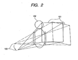
- Fig. 2 shows the outline of a cone beam X-ray CT device (or scanner).
- an X-ray irradiated from an X-ray tube 103 is absorbed and attenuated inside the body of a subject 102, and the X-ray passed the subject 102 is detected on a surface sensor 101. Then, the X-ray tube 103 and the surface sensor 101 are rotated around the subject 102 without changing the relative physical relationship between the X-ray tube 103 and the surface sensor 101, whereby the projection image data of the subject 102 as much as one rotation is acquired.
- the projection image data acquired like this is subjected to a reconstruction process, whereby the tomographic image of the subject 102 is acquired.
- the subject 102 may be rotated as much as one rotation instead of the rotation of the X-ray tube 103 and the surface sensor 101.
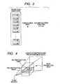
- a convolution process is first executed to the projection image data as shown in Fig. 3 , and the convolution-processed projection image data is then subjected to back projection to each pixel of the reconstruction image as shown in Fig. 4 .
- a multiprocessor To execute the reconstruction process at high speed, for example, a multiprocessor is used.
- the method of achieving the high-speed reconstruction process by using the multiprocessor is described in " Reconstruction of 3-D X-ray Computerized Tomography Images Using a Distributed Memory Multiprocessor System", TOHRU SASAKI and YASUSHI FUKUDA, Information Processing Society of Japan Transaction, Vol. 38, No. 9 (hereinafter called the document 1).
- the parallel processes are achieved by using the plural processors, and also the data is transferred at high speed. That is, the high-speed reconstruction process is achieved mainly by hardware.
- the projection image data acquired all over the projection angles is the line data corresponding to the one-dimensional fan beam.
- the projection image data is the two-dimensional image data, whereby an amount of data necessary in the process is huge. For this reason, if the convolution process is executed wholly to the huge amount of data as in the method described in the document 1, it is inefficient. Thus, it is impossible to achieve the high-speed reconstruction process by the hardware. Moreover, even if the parallel processes are executed, a huge amount of projection image data must be stored in the local memory of each of the processing units, whereby the capacity of each local memory must be made with high cost.
- EP-A-1079330 discloses an X-ray computed tomography (CT) system in which an over-sampling detector array and improved re-sampling technique are employed to prepare projection data for reconstruction.
- the over-sampling detector array employs a plurality of detectors, with the height of each detector row being less than the slice thickness.
- the improved re-sampling technique involves a re-sampling of the over-sampled data, and combination thereof prior to reconstruction, thereby enhancing resulting image quality in a manner that improves system throughput.
- an X-ray radiography method as specified in claim 14.
- the present invention is intended to provide an image processing device and an image processing method which can achieve a high-speed reconstruction process of a cone beam CT image.
- Fig. 1 is a schematic view for schematically showing entire structure of a cone beam X-ray CT device having an image processing device according to the embodiment of the present invention.
- An X-ray radiography system control unit 106 executes a radiography control of an entire device, image collection, an image process and an image output.
- an X-ray radiography system control unit 106 instructs an X-ray generator control unit 104 to generate the X-ray
- an X-ray source 103 controlled by the X-ray generator control unit 104 generates the X-ray.
- the X-ray generated by the X-ray source 103 transmits through a patient 102 being a radiographic object, and the transmitted X-ray is detected by an X-ray detector (area sensor) 101.
- the detected X-ray is input to an image input unit 105 as projection image data.
- projection images are collected every determined rotation angle while rotating the X-ray source 103 and the X-ray detector 101 around the patient by treating the patient 102 being the radiographic object as a center of rotation.
- the patient 102 may be rotated while maintaining the location relationship between the X-ray source 103 and the X-ray detector 101 in a manner that the patient is kept in a state capable of rotating by providing a rotation table (not shown) or the like at a portion where the patient 102 is located.
- a preprocess including the correction of the X-ray detector 101 and a log conversion process or an image process such as a reconstruction process or the like is executed by an image processing unit 107, then a tomographic images group is formed.
- This image processing unit 107 corresponds to the image processing device according to the embodiment of the present invention.
- the formed tomographic images group is displayed on a diagnostic monitor 109, stored in an image storage unit 108 or output to a printer 112, a diagnostic work station 113 and/or an image database 114 through a network 111.
- Various operations such as a window operation of display, a changeover display operation of a tomographic image in the direction of a body axis, an axial plane (slice plane) converting operation, a three-dimensional surface display operation and the like are executed by an operation unit 110.
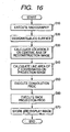
- Fig. 16 is a flowchart for explaining an operation to be executed in the cone beam X-ray CT device.
- a simple radiography for designating a slice position and the CT radiography for obtaining the projection image data are executed (step S10).
- the simple radiography since the area sensor is used as the X-ray detector 101, if the simple radiography is executed by stilling the device and an examinee, an image for designating the slice position can be obtained.
- the high speed process is not required in a still image. Therefore, if the radiography is executed by setting a read-out mode to a high precision read-out, a more preferable high precision still image can be obtained. It is allowed that a projection image radiographed from a specific projection angle is used as a simple radiography image in case of executing the CT radiography for obtaining the projection data without executing the simple radiography.
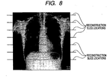
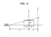
- a slice surface of a tomographic image to be reconstructed is designated as shown in Fig. 8 by using the obtained simple radiography image (step S20).
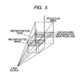
- Projection data necessary for reconstructing a tomographic image on a certain arbitrary slice position is limited within a certain narrow area in a projection image as shown in Fig. 5 .
- the above location relationship is indicated by the location relationship shown in Fig. 6 .
- a line area of the Z'-coordinate on the projection image of the slice position, where the Z-coordinate of a reconstruction image is Z i is represented by the following area.
- reference symbol R denotes a radius of a reconstruction area (half of vertical length and lateral length of a reconstruction image)
- reference symbol D denotes distance between the X-ray source and a center of rotation (center of the reconstruction image)
- reference numeral S denotes distance between the center of rotation and the sensor.
- the location Z i on the central axis of the reconstruction image can be calculated from the location Z' of the slice position by the following expression 2 (step S30).
- Zi Z ′ ⁇ D D + S
- reference symbol R denotes the radius of the reconstruction area (half of vertical length and lateral length of a reconstruction image)
- reference symbol D denotes distance between the X-ray source and the center of rotation (center of the reconstruction image)
- reference numeral S denotes distance between the center of rotation and the sensor.
- a line area of the Z'-coordinate on the projection image is represented by the following area (expression 3). This line area is calculated by the image process unit 107 on the basis of a location of the designated slice position (step S40).
- reference symbol R denotes the radius of the reconstruction area (half of vertical length and lateral length of a reconstruction image)
- reference symbol D denotes distance between the X-ray source and the center of rotation (center of the reconstruction image)
- reference numeral S denotes distance between the center of rotation and the sensor.
- the image process unit 107 executes the convolution process to the line area in the projection image data (step S50).
- the convolution process is executed by taking convolution of lateral line data of the projection image data and one-dimensional data called a reconstruction function.
- a back projection process is executed by using the projection image data to which the convolution process was executed (step S60).
- the back projection process is executed in a manner, where as to each of pixels of the reconstruction image, the coordinate of a dot formed on the projection image by transmitting the X-ray through that each pixel of the reconstruction image is obtained, and pixel values of four dots in the vicinity of a location of the obtained coordinate are calculated by the interpolation then the obtained pixel values are summed up.
- Fig. 11 dots P1 to P4 are central locations of the four pixels in the vicinity of the projected dot. If it is assumed that distances between the projected dot and these four dots are respectively d1 to d4 and the pixel values of the four pixels in the vicinity of the projected dot are respectively Q1 to Q4, the interpolation may be executed by using back projection data V calculated by the following expressions 4.
- a ⁇ 1 Q ⁇ 1 ⁇ d ⁇ 2 + Q ⁇ 2 ⁇ d ⁇ 1 d ⁇ 1 + d ⁇ 2
- a ⁇ 2 Q ⁇ 3 ⁇ d ⁇ 2 + Q ⁇ 4 ⁇ d ⁇ 1 d ⁇ 1 + d ⁇ 2
- V A ⁇ 1 ⁇ d ⁇ 4 + Q ⁇ 2 ⁇ d ⁇ 3 d ⁇ 3 + d ⁇ 4
- the tomographic image of the designated slice position can be formed.
- the formed tomographic image is stored in the image storage unit 108 or displayed on the diagnostic monitor 109 (step S70).
- an area necessary for reconstruction in the projection image is determined from the slice position to be reconstructed, and the convolution process and the back projection process are executed by using the determined area. Accordingly, the useless convolution and back projection processes can be omitted, thereby shortening a processing time of the reconstruction process.
- the present embodiment it is structured that in a case of selecting plural portions of the slice positions of the tomographic image, the processes in the steps S30 to S60 indicated in a flowchart shown in Fig. 16 are executed in parallel in the respective process units.
- various architectures exist, however in the present embodiment, for example, the multi-computer MIMD architecture is used. If this multi-computer MIMD architecture is illustrated, Fig. 12 is given. As shown in Fig. 12 , in the multi-computer MIMD architecture, memories are provided in the respective process units.
- the reconstruction images of the respective slice positions are allocated to the respective process units. Then, only data for the line area of the projection image necessary for the allocated reconstruction image is stored in the memory of each of the process units. The above conception is shown in Fig. 13 .
- the pixel number of the reconstruction image row is equal to the number of the process units, and initially, the each projection image data is equally divided into data, of which the number is the number of the respective units, and the divided data is transferred to the memories of the respective process units.
- the convolution processes are executed to the equally divided projection image data in the respective process units.
- the projection image data is equally divided in order to improve an effect of the parallelizing by uniformly dispersing the processing load on the respective process unit.
- the back projection process is executed by using the projection image data resulted in executing the convolution process.
- the line area of the projection image data distributed to each of the process units at this time is not sufficiently satisfied by the equally divided line area.
- the above transfer is executed by using an interconnection network. Then, after preparing necessary data, the back projection process is independently executed every the process unit.
- the slice position to be reconstructed is divided into plural blocks, and areas of the projection image corresponding to the divided blocks are cut out, and a unit of process is set every the block as local data of the each block, then a parallel process is executed by allocating the units of process to the units of operation. According to the above parallelizing, capacity of a local memory of each of the process units can be minimized and the costs can be reduced.
- the embodiment of the present invention can be realized by executing the programs by, for example, a computer. Further, a means for supplying the programs to the computer, for example, a recording medium which can be read by the computer such as a CD-ROM or the like storing the programs or a transmission/reception medium such as an internet or the like for transmitting and receiving the programs are also can be applied as the embodiment of the present invention. Further, the above programs can be applied as the embodiment of the present invention. The above programs, the recording medium, the transmission/reception medium and the program products are included in the scope of the present invention.
Landscapes
- Physics & Mathematics (AREA)
- General Physics & Mathematics (AREA)
- Engineering & Computer Science (AREA)
- Theoretical Computer Science (AREA)
- Apparatus For Radiation Diagnosis (AREA)
- Image Processing (AREA)
- Image Analysis (AREA)
Applications Claiming Priority (1)
| Application Number | Priority Date | Filing Date | Title |
|---|---|---|---|
| JP2004239690A JP4769441B2 (ja) | 2004-08-19 | 2004-08-19 | 画像処理装置及び画像処理方法 |
Publications (2)
| Publication Number | Publication Date |
|---|---|
| EP1628261A1 EP1628261A1 (en) | 2006-02-22 |
| EP1628261B1 true EP1628261B1 (en) | 2010-05-26 |
Family
ID=35445759
Family Applications (1)
| Application Number | Title | Priority Date | Filing Date |
|---|---|---|---|
| EP05255111A Expired - Lifetime EP1628261B1 (en) | 2004-08-19 | 2005-08-18 | Tomographic image reconstruction device and method |
Country Status (4)
| Country | Link |
|---|---|
| US (2) | US7317781B2 (https=) |
| EP (1) | EP1628261B1 (https=) |
| JP (1) | JP4769441B2 (https=) |
| DE (1) | DE602005021437D1 (https=) |
Families Citing this family (12)
| Publication number | Priority date | Publication date | Assignee | Title |
|---|---|---|---|---|
| JP4769441B2 (ja) * | 2004-08-19 | 2011-09-07 | キヤノン株式会社 | 画像処理装置及び画像処理方法 |
| US8594445B2 (en) | 2005-11-29 | 2013-11-26 | Adobe Systems Incorporated | Fast bilateral filtering using rectangular regions |
| US7675524B1 (en) | 2007-05-17 | 2010-03-09 | Adobe Systems, Incorporated | Image processing using enclosed block convolution |
| US7920741B2 (en) | 2007-05-31 | 2011-04-05 | Adobe Systems Incorporated | System and method for image processing using integral histogram convolution |
| US7769126B2 (en) * | 2007-09-25 | 2010-08-03 | Canon Kabushiki Kaisha | Computed tomography system |
| JP5241316B2 (ja) * | 2008-05-13 | 2013-07-17 | キヤノン株式会社 | 画像処理装置及び画像処理方法 |
| US8315473B1 (en) | 2008-08-22 | 2012-11-20 | Adobe Systems Incorporated | Variably fast and continuous bilateral approximation filtering using histogram manipulations |
| US8655097B2 (en) | 2008-08-22 | 2014-02-18 | Adobe Systems Incorporated | Adaptive bilateral blur brush tool |
| JP5398198B2 (ja) * | 2008-08-28 | 2014-01-29 | 株式会社東芝 | X線コンピュータ断層撮影装置 |
| US8147139B2 (en) * | 2008-10-13 | 2012-04-03 | George Papaioannou | Dynamic biplane roentgen stereophotogrammetric analysis |
| JP6073607B2 (ja) * | 2012-09-06 | 2017-02-01 | 東芝メディカルシステムズ株式会社 | X線ct装置、x線ct装置の画像表示プログラム |
| DE102013210855A1 (de) * | 2013-06-11 | 2014-12-11 | Siemens Aktiengesellschaft | Verfahren zu einer Anpassung einer Schichtpositionierung innerhalb eines Schichtprotokolls für eine Magnetresonanzuntersuchung sowie eine Magnetresonanzvorrichtung zur Ausführung des Verfahrens |
Family Cites Families (12)
| Publication number | Priority date | Publication date | Assignee | Title |
|---|---|---|---|---|
| US5802134A (en) * | 1997-04-09 | 1998-09-01 | Analogic Corporation | Nutating slice CT image reconstruction apparatus and method |
| US6188745B1 (en) | 1998-09-23 | 2001-02-13 | Analogic Corporation | CT scanner comprising a spatially encoded detector array arrangement and method |
| JP3825935B2 (ja) | 1999-04-08 | 2006-09-27 | キヤノン株式会社 | 画像処理装置及び画像処理方法及び記録媒体及び画像処理システム |
| DE10022468A1 (de) * | 1999-05-10 | 2001-10-11 | Shimadzu Corp | Röntgen-CT-Vorrichtung |
| US6263008B1 (en) * | 1999-08-16 | 2001-07-17 | Analogic Corporation | Over-sampling detector array and re-sampling technique for a cone-beam computed tomography system |
| CN1658796A (zh) * | 2002-06-03 | 2005-08-24 | 株式会社日立医药 | 多层面x线ct装置 |
| JP2004180715A (ja) * | 2002-11-29 | 2004-07-02 | Toshiba Corp | X線コンピュータ断層撮影装置 |
| WO2004071301A1 (ja) * | 2003-02-14 | 2004-08-26 | Hitachi Medical Corporation | X線ct装置 |
| JP4498023B2 (ja) | 2004-06-15 | 2010-07-07 | キヤノン株式会社 | X線ct装置 |
| JP2006000225A (ja) | 2004-06-15 | 2006-01-05 | Canon Inc | X線ct装置 |
| JP4769441B2 (ja) * | 2004-08-19 | 2011-09-07 | キヤノン株式会社 | 画像処理装置及び画像処理方法 |
| JP4585815B2 (ja) | 2004-09-03 | 2010-11-24 | キヤノン株式会社 | 情報処理装置、撮影システム、吸収係数補正方法、及びコンピュータプログラム |
-
2004
- 2004-08-19 JP JP2004239690A patent/JP4769441B2/ja not_active Expired - Fee Related
-
2005
- 2005-08-12 US US11/202,092 patent/US7317781B2/en not_active Expired - Fee Related
- 2005-08-18 DE DE602005021437T patent/DE602005021437D1/de not_active Expired - Lifetime
- 2005-08-18 EP EP05255111A patent/EP1628261B1/en not_active Expired - Lifetime
-
2007
- 2007-09-06 US US11/851,084 patent/US7486765B2/en not_active Expired - Fee Related
Also Published As
| Publication number | Publication date |
|---|---|
| JP2006055336A (ja) | 2006-03-02 |
| EP1628261A1 (en) | 2006-02-22 |
| US20080008374A1 (en) | 2008-01-10 |
| US20060039526A1 (en) | 2006-02-23 |
| JP4769441B2 (ja) | 2011-09-07 |
| DE602005021437D1 (de) | 2010-07-08 |
| US7317781B2 (en) | 2008-01-08 |
| US7486765B2 (en) | 2009-02-03 |
Similar Documents
| Publication | Publication Date | Title |
|---|---|---|
| US7486765B2 (en) | Image processing device and image processing method | |
| US5463666A (en) | Helical and circle scan region of interest computerized tomography | |
| US7424089B2 (en) | System and method for reconstructing image by using straight-line trajectory scan | |
| EP0492895B1 (en) | Reconstructing 3-D images | |
| US5390112A (en) | Three-dimensional computerized tomography scanning method and system for imaging large objects with smaller area detectors | |
| JP4342164B2 (ja) | コンピュータ断層撮影装置 | |
| US8116426B2 (en) | Computed tomography device and method using circular-pixel position-adaptive interpolation | |
| US5341460A (en) | Method and apparatus for producing a three-dimensional computerized tomography image of an object with improved conversion of cone beam data to radon data | |
| US20030035513A1 (en) | Image producing method and X-ray CT apparatus | |
| JP2001087260A (ja) | ヘリカル・スキャン円錐形ビームによるコンピュータ断層撮影システムにおける三次元画像を再構成するための装置および方法 | |
| US5862198A (en) | Pre-calculated hitlist for reducing run-time processing of an exact cone beam reconstruction algorithm | |
| JP6074450B2 (ja) | Ctシステム | |
| US9704223B2 (en) | Method and system for substantially reducing cone beam artifacts based upon adaptive scaling factor in circular computer tomography (CT) | |
| JP2004113785A (ja) | コンピュータ断層撮影法における画像形成方法およびこの方法を実施するためのct装置 | |
| EP0849711A2 (en) | Method and apparatus for cone beam imaging | |
| US7728834B2 (en) | Method and apparatus for reconstructing a three-dimensional image volume from two-dimensional projection images | |
| US20050175139A1 (en) | Image reconstructing method and X-ray CT apparatus | |
| US20070153972A1 (en) | X-ray ct apparatus | |
| US20050151736A1 (en) | Method and device for constructing an image in a spatial volume | |
| US7809100B2 (en) | Rebinning for computed tomography imaging | |
| JPH09192126A (ja) | 画像再構成処理装置 | |
| US5901195A (en) | Two-step radon inversion processing for φ-planes having local radon origins | |
| EP1728207B1 (en) | Multiple focus acquisition | |
| US6154515A (en) | Computerized tomography reconstruction using shadow zone patching | |
| JP2000083948A (ja) | 断層写真画像を作る装置と方法 |
Legal Events
| Date | Code | Title | Description |
|---|---|---|---|
| PUAI | Public reference made under article 153(3) epc to a published international application that has entered the european phase |
Free format text: ORIGINAL CODE: 0009012 |
|
| AK | Designated contracting states |
Kind code of ref document: A1 Designated state(s): AT BE BG CH CY CZ DE DK EE ES FI FR GB GR HU IE IS IT LI LT LU LV MC NL PL PT RO SE SI SK TR |
|
| AX | Request for extension of the european patent |
Extension state: AL BA HR MK YU |
|
| 17P | Request for examination filed |
Effective date: 20060822 |
|
| 17Q | First examination report despatched |
Effective date: 20060921 |
|
| AKX | Designation fees paid |
Designated state(s): DE FR GB |
|
| GRAP | Despatch of communication of intention to grant a patent |
Free format text: ORIGINAL CODE: EPIDOSNIGR1 |
|
| RTI1 | Title (correction) |
Free format text: TOMOGRAPHIC IMAGE RECONSTRUCTION DEVICE AND METHOD |
|
| GRAS | Grant fee paid |
Free format text: ORIGINAL CODE: EPIDOSNIGR3 |
|
| GRAA | (expected) grant |
Free format text: ORIGINAL CODE: 0009210 |
|
| AK | Designated contracting states |
Kind code of ref document: B1 Designated state(s): DE FR GB |
|
| REG | Reference to a national code |
Ref country code: GB Ref legal event code: FG4D |
|
| REF | Corresponds to: |
Ref document number: 602005021437 Country of ref document: DE Date of ref document: 20100708 Kind code of ref document: P |
|
| PLBE | No opposition filed within time limit |
Free format text: ORIGINAL CODE: 0009261 |
|
| STAA | Information on the status of an ep patent application or granted ep patent |
Free format text: STATUS: NO OPPOSITION FILED WITHIN TIME LIMIT |
|
| 26N | No opposition filed |
Effective date: 20110301 |
|
| REG | Reference to a national code |
Ref country code: DE Ref legal event code: R097 Ref document number: 602005021437 Country of ref document: DE Effective date: 20110228 |
|
| PGFP | Annual fee paid to national office [announced via postgrant information from national office to epo] |
Ref country code: DE Payment date: 20140831 Year of fee payment: 10 |
|
| PGFP | Annual fee paid to national office [announced via postgrant information from national office to epo] |
Ref country code: FR Payment date: 20140827 Year of fee payment: 10 Ref country code: GB Payment date: 20140822 Year of fee payment: 10 |
|
| REG | Reference to a national code |
Ref country code: DE Ref legal event code: R119 Ref document number: 602005021437 Country of ref document: DE |
|
| GBPC | Gb: european patent ceased through non-payment of renewal fee |
Effective date: 20150818 |
|
| REG | Reference to a national code |
Ref country code: FR Ref legal event code: ST Effective date: 20160429 |
|
| PG25 | Lapsed in a contracting state [announced via postgrant information from national office to epo] |
Ref country code: GB Free format text: LAPSE BECAUSE OF NON-PAYMENT OF DUE FEES Effective date: 20150818 Ref country code: DE Free format text: LAPSE BECAUSE OF NON-PAYMENT OF DUE FEES Effective date: 20160301 |
|
| PG25 | Lapsed in a contracting state [announced via postgrant information from national office to epo] |
Ref country code: FR Free format text: LAPSE BECAUSE OF NON-PAYMENT OF DUE FEES Effective date: 20150831 |