EP1628153A2 - Automatic focus detection device and microscope system having the same - Google Patents
Automatic focus detection device and microscope system having the same Download PDFInfo
- Publication number
- EP1628153A2 EP1628153A2 EP05107628A EP05107628A EP1628153A2 EP 1628153 A2 EP1628153 A2 EP 1628153A2 EP 05107628 A EP05107628 A EP 05107628A EP 05107628 A EP05107628 A EP 05107628A EP 1628153 A2 EP1628153 A2 EP 1628153A2
- Authority
- EP
- European Patent Office
- Prior art keywords
- objective lens
- light
- sample
- illumination
- focus detection
- Prior art date
- Legal status (The legal status is an assumption and is not a legal conclusion. Google has not performed a legal analysis and makes no representation as to the accuracy of the status listed.)
- Withdrawn
Links
- 238000001514 detection method Methods 0.000 title claims description 127
- 238000005286 illumination Methods 0.000 claims abstract description 138
- 238000005266 casting Methods 0.000 claims abstract description 8
- 230000003287 optical effect Effects 0.000 claims description 34
- 230000005284 excitation Effects 0.000 claims description 13
- 238000006243 chemical reaction Methods 0.000 claims description 4
- 230000001419 dependent effect Effects 0.000 abstract description 2
- 238000003384 imaging method Methods 0.000 description 10
- 230000008901 benefit Effects 0.000 description 8
- 230000004048 modification Effects 0.000 description 8
- 238000012986 modification Methods 0.000 description 8
- 238000010586 diagram Methods 0.000 description 6
- 230000001413 cellular effect Effects 0.000 description 4
- 239000007850 fluorescent dye Substances 0.000 description 4
- 238000005562 fading Methods 0.000 description 3
- 108091008695 photoreceptors Proteins 0.000 description 3
- 230000001276 controlling effect Effects 0.000 description 2
- 230000002596 correlated effect Effects 0.000 description 2
- 230000007547 defect Effects 0.000 description 2
- 230000004907 flux Effects 0.000 description 2
- 229910052736 halogen Inorganic materials 0.000 description 2
- 150000002367 halogens Chemical class 0.000 description 2
- QSHDDOUJBYECFT-UHFFFAOYSA-N mercury Chemical compound [Hg] QSHDDOUJBYECFT-UHFFFAOYSA-N 0.000 description 2
- 238000003825 pressing Methods 0.000 description 2
- 230000008859 change Effects 0.000 description 1
- 230000000875 corresponding effect Effects 0.000 description 1
- 239000000463 material Substances 0.000 description 1
- 229910052751 metal Inorganic materials 0.000 description 1
- 239000002184 metal Substances 0.000 description 1
- 239000004065 semiconductor Substances 0.000 description 1
- 238000010186 staining Methods 0.000 description 1
Images




Classifications
-
- G—PHYSICS
- G02—OPTICS
- G02B—OPTICAL ELEMENTS, SYSTEMS OR APPARATUS
- G02B21/00—Microscopes
- G02B21/24—Base structure
- G02B21/241—Devices for focusing
- G02B21/245—Devices for focusing using auxiliary sources, detectors
-
- G—PHYSICS
- G02—OPTICS
- G02B—OPTICAL ELEMENTS, SYSTEMS OR APPARATUS
- G02B21/00—Microscopes
- G02B21/06—Means for illuminating specimens
- G02B21/08—Condensers
- G02B21/10—Condensers affording dark-field illumination
-
- G—PHYSICS
- G02—OPTICS
- G02B—OPTICAL ELEMENTS, SYSTEMS OR APPARATUS
- G02B21/00—Microscopes
- G02B21/24—Base structure
- G02B21/241—Devices for focusing
- G02B21/244—Devices for focusing using image analysis techniques
-
- G—PHYSICS
- G02—OPTICS
- G02B—OPTICAL ELEMENTS, SYSTEMS OR APPARATUS
- G02B7/00—Mountings, adjusting means, or light-tight connections, for optical elements
- G02B7/28—Systems for automatic generation of focusing signals
- G02B7/285—Systems for automatic generation of focusing signals including two or more different focus detection devices, e.g. both an active and a passive focus detecting device
Definitions
- the present invention relates to an automatic focus detection device employed in a microscope.
- defect detection devices With devices for detecting defects such as cracks, foreign material, and so forth, on a semiconductor wafer or a metal surface, defect detection devices are known having a function of automatic focusing.
- Japanese Patent Application Publication No. 2003-7243 disclosed is a focus detection technique in which a laser beam is incident onto a sample so as to capture dark field images of scattered light from the sample, and the sample point is determined to be the focal point at which the dark field image exhibits the greatest brightness.
- An automatic focus detection device comprises: an illumination light means for emitting infrared or near-infrared light; a dark field illumination means for casting illumination light emitted from the illumination light means onto a sample stored in a container; an image-capturing means for capturing a dark field image of the sample through an objective lens; an adjustment means for adjusting a distance between the sample and the objective lens; a position detection means for detecting the distance between the sample and the objective lens; a storage means for storing the plurality of detected distances between the sample and the objective lens as position information; and a computation means for comparing a plurality of brightness signals of a predetermined number of dark field images each captured while changing the distance between the sample and the objective lens by the adjustment means and determines a specific dark field image having a maximum brightness signal, wherein the focus position, at which the objective lens is in focus on the sample, is detected based upon position information corresponding to a position, at which the maximum brightness of the dark field image is determined by the computation means, among a
- An automatic focus detection device comprises: a first automatic focus detection device according to the first aspect of the present invention; a second automatic focus detection means for casting illumination light onto the base of the container storing the sample through the objective lens and detects light reflected from the base through the objective lens by receiving the reflected light on a photo sensor, so that the second automatic focus detection device detects the focus position, at which the objective lens is in focus on the sample, based upon the position at which the photo sensor receives the reflected light; a determination means for determining whether or not the photo sensor have received the reflected light; and a switching means for switching a focus detection by the second automatic focus detection device to the first automatic focus detection device in the event that the determination means determines that the reflected light is not detected by the photo sensor.
- the dark field illumination means can be disposed around the perimeter of an end of a lens barrel of the objective lens.
- the dark field illumination means comprises an epi illumination means in which a part of an optical path of the epi illumination means is parallel to an optical axis of the objective lens.
- the dark field illumination means comprises an annular illumination means including a light source disposed outer the lens barrel and an annual-shaped total reflection mirror disposed inner the lens barrel and reflecting light emitted from the light source as an annual-shaped light in a direction of the axis of the objective lens.
- the automatic focus detection device can be used together with the following means or elements to construct a microscope system.
- the microscope system according to the third aspect of the present invention comprises: an epi fluorescence illumination means for emitting excitation light onto the sample so as to cause emission of fluorescence, and the objective lens forming a fluorescence microscopic image of the sample.
- the annual-shaped total reflection mirror is disposed between the objective lens and the epi fluorescence illumination means. It is also possible that the epi fluorescence illumination means is disposed between the objective lens and the annual-shaped total reflection mirror.
- a focus detection device comprises: an illumination light means for emitting infrared or near-infrared light; a dark field illumination means for casting illumination light, which has been emitted from the illumination light source, onto a sample; a photoelectric conversion means for detecting scattered light scattered from the sample through an objective lens; and a computation means for computing a focus position, at which the objective lens is in focus on the sample, based upon electric signals converted by the photoelectric conversion means.
- the device acquires scattered light from the sample due to infrared dark field illumination, thereby obtaining focus detection signals with high precision while preventing damage of the sample and fading of fluorescent dye.
- FIG. 1 through 4 A microscope system including an automatic focus detection device according to a first embodiment of the present invention will be explained referring to Fig. 1 through 4. Note that the devices are shown in Figs. 1 through 4 using the three-dimensional coordinate system.
- the microscope system comprises an optical microscope 1 and an automatic focusing (which will also be abbreviated as "AF” hereafter) control system 80.
- AF automatic focusing
- the optical microscope 1 includes: an epi fluorescence illumination device 10; a transmitted illumination device 20; a holding unit 30 for holding an objective lens 31; a stage 33 for mounting a petri dish 100 for storing an organism-originated tissue sample (hereafter referred to simply as "tissue sample”); a position detection unit 40 for detecting the position of the holding unit 30 in the Z direction; a driving unit 43 for moving the holding unit 30 in the Z direction; an AF slit illumination/detection device 50; an AF dark field illumination device 60; and a CCD camera 70.
- tissue sample an organism-originated tissue sample
- the AF control system 80 includes: a motor driving circuit 81; a position detection circuit 82; an AF slit illumination driving circuit 83; a reflected-slit-light detection circuit 84; an AF dark field illumination control circuit 85; an image comparison computation circuit 86; a camera control circuit 87; and a microcomputer 88 controlling the AF control system 80.
- a motor driving circuit 81 Connected to the microcomputer 88 is an input unit 88a, through which the user can input data in the AF control system 80.
- a display 89 is connected to the camera control circuit 87.
- the motor driving circuit 81 is electrically connected to a motor of the driving unit 43 so as to control the motor.
- the position detection circuit 82 is electrically connected to a position sensor of the position detection unit 40, thereby allowing detection of the position of the holding unit 30 along the Z axis.
- the AF slit illumination driving circuit 83 is electrically connected to an LED light source of the AF slit illumination/detection device 50, thereby allowing control of on/off actions and the illumination intensity of LED light source.
- the reflected-slit-light detection circuit 84 is electrically connected to a photo-sensor of the AF slit illumination/detection device 50, thereby allowing detection of the position of the reflected slit light on the photo-sensor.
- the AF dark field illumination control circuit 85 is electrically connected to an LED light source of the AF dark field illumination device 60, thereby allowing control of on/off actions and the illumination intensity of the LED light source.
- the image comparison computation circuit 86 is electrically connected to an imaging device of the CCD camera 70, thereby allowing capturing images of the tissue sample at predetermined positions along the Z axis and implementing comparison/computation of the brightness (sharpness) of the captured images.
- the camera control circuit 87 controls the gain, the imaging timing, and so forth, for the CCD camera 70.
- the epi fluorescence illumination device 10 includes: a mercury vapor lamp 11; a collector lens 12; a field lens 13; and a filter block 14 housing an excitation filter 14a and a dichroic mirror 14b.
- the transmitted illumination device 20 includes: a halogen lamp 21; a collector lens 22; a mirror 23; a field lens 24; and a condenser lens 25.
- the objective lens 31 comprising a lens barrel an infinity optical system housed therein is mounted to a nosepiece 32 fixed on the holding unit 30.
- the holding unit 30 has a leg portion 30a extending in the negative Z direction.
- the leg portion 30a is connected to the driving unit 43, thereby allowing the leg portion 30a to be moved in the Z direction by actions of the driving unit 43.
- the objective lens 31 is moved in the Z direction accompanying movement of the holding unit 30 in the Z direction.
- the stage 33 can be moved in the X-Y directions, i.e., two-dimensional directions, and the focus detection for tissue sample is made by moving the objective lens 31 in the Z direction.
- the position of the objective lens 31 is measured in the Z direction by the position detection unit 40.
- the position detection unit 40 consists of a linear scale 41 and a position sensor 42 fixed to the leg portion 30a.
- Fig. 3 shows the AF slit illumination/detection device 50 including: an LED light source 51 for emitting near-infrared light L4; a collector lens 52; a slit 53; and a dichroic mirror 55. Furthermore, the CCD camera 70 including an imaging device 70a is mounted on the left portion (in the negative X direction) of the optical microscope 1 through a cylinder 71.
- the AF slit illumination/detection device 50 is the first focus detection device.
- the AF dark field illumination device 60 is held by a support 61 fixed on the holding unit 30. Accordingly, the AF dark field illumination device 60 is moved in the Z direction accompanying the movement of the holding unit 30 in the Z direction.
- the AF dark field illumination device 60 is provided around the top end of the lens barrel of the objective lens 31.
- the AF dark field illumination device 60 is the second focus detection device.
- the AF dark field illumination device 60 comprises a pair of light-source components each of which includes an LED light source 63 for emitting infrared light L5 and a condenser lens 64.
- the pair of light-source components is symmetrically disposed in the direction with the objective lens 31 introduced therebetween.
- an LED light source for emitting near-infrared light may be employed as the LED light source 63.
- Electric power is supplied to each LED light source 63 through a power cable 62. As shown in the drawing, each infrared light from each LED light source 63 converges at a focal point of the objective lens 31.
- the AF dark field illumination device 60 may have a configuration of an annular illumination system which emits the infrared light L5 to illuminate the tissue sample S.
- multiple objective lenses 31, each of which has different focal distance, are mounted on the nosepiece 32 and the user can replace a desired objective lens on the optical path by turning the nosepiece 32.
- both the support 61 of the AF dark field illumination device 60 and the nosepiece 32 are fixed on the holding unit 30. This configuration allows the user to switch the objective lens 31 while maintaining the converging position of the infrared light L5 at the focal point of the objective lens 31.
- the optical microscope 1 may have another configuration in which the relation between the converging position of the infrared light L5 and the position of the petri dish 100 can be maintained regardless switching of the objective lens 31 and adjusting of the position of the objective lens 31 in the Z direction (or the tissue sample S).
- excitation light L1 having an wavelength in an ultraviolet region which has been emitted from the mercury vapor lamp 11, passes through the collector lens 12 and the field lens 13. Then, excitation light L1 enter the excitation filter 14a allowing the excitation light L1 having a predetermined wavelength region to pass through and enter the _dichroic mirror 14b.
- the dichroic mirror 14b reflects the excitation light of a predetermined wavelength region inherent to the dichroic mirror 14b toward the Z direction.
- the reflected excitation light is introduced into the objective lens 31 from below.
- the excitation light L1, which has passed through the objective lens 31, passes through the base 101 of the petri dish 100, thereby illuminating the tissue sample S.
- the illumination of the excitation light L1 causes emission of fluorescence L2 from the portions stained with fluorescent dye in the tissue sample S.
- the fluorescence L2 which has a longer wavelength than that of the excitation light L1, passes through the base 101, and is introduced into the objective lens 31. Then, the fluorescence L2 passes through the dichroic mirror 14b and an imaging lens 34. The fluorescence L2, which has passes through the imaging lens 34, is split into two by a half prism 35. One part of the fluorescence L2 having a light quantity of 20% is introduced into an eyepiece 39 through total reflection prisms 36 and 37, and a mirror 38, thereby allowing the user to observe a fluorescent image. The other part of the fluorescence L2 having a light quantity of 80% passes in the negative X direction, and forms an image on the imaging device 70a of the CCD camera 70, thereby allowing capturing of the fluorescent image.
- a transmitted-light phase contrast microscope may employ an optical system in which the transmitted illumination device 20 is provided with a ring iris and the objective lens 31 is provided with a phase ring is conjugated with the ring iris.
- the near-infrared light L4 emitted from the LED light source 51 of the AF slit illumination/detection device 50 is converged to the slit 53 by the collector lens 52.
- the near-infrared light L4 adjusted in the form of slit light passes through the converging lens 54, and is reflected by the dichroic mirror 55 in the Z direction. Then, the near-infrared light L4 thus reflected is incident onto the base 101 of the petri dish 100 through the objective lens 31.
- the slit light is split into two along the longitudinal center line. With such a configuration, one part of the slit light is shielded, and the other part thereof is used as illumination light.
- the near-infrared light L4 employed in the present invention is not restricted to that in the form of slit light, rather an arrangement may be made employing the near-infrared light L4 in the form of spot light.
- the near-infrared light (reflected slit light) L4 reflected by the base 101 passes through the objective lens 31, and is reflected by the dichroic mirror 55, thereby being introduced into a photo-sensor (not shown) included in the AF slit illumination/detection device 50.
- the photo-sensor is a line sensor or an area sensor having a plurality of pixels. The photo-sensor detects the incident position of the reflected slit light L4 on the photo-receptor face of the photo-sensor, which is dependent upon the reflection angle thereof.
- the reflected slit light L4 is incident on the center of the photo-receptor face of the photo-sensor, determination is made that the base 101 is positioned at the focal point of the objective lens 31, i.e., the objective lens 31 is in focus condition.
- the photo-sensor outputs detection results with regard to the incident position of the slit light on the photo-receptor face to the reflected-slit-light detection circuit 84.
- the position sensor 42 of the position detection unit 40 outputs the position information to the position detection circuit 82, which indicates the position of the objective lens 31 in the Z direction.
- the detection results of the reflected slit light L4 is correlated with the position of the objective lens 31 along the Z axis.
- the reflected slit light L4 there are two types of reflected light in the reflected slit light L4. One is the first reflected light which is reflected by the outer face P1 of the base 101. The other is the second reflected light which is reflected by the inner face P2. Description will be made later regarding detection of these two types of reflected light.
- the LED light source 63 of the AF dark field illumination device 60 is supplied with electric power through the power cable 62, thereby emitting the infrared light L5.
- the infrared light L5 emitted from the LED light source 63 is converged by the converging lens 64, and is incident onto the tissue sample S in the petri dish 100 with an oblique angle.
- the infrared light L5 incident onto the tissue sample S causes scattered light L6 therefrom.
- a part of the scattered light L6 passes through the objective lens 31, and is introduced into the imaging lens 34 through the dichroic mirror 55 and the filter block 14, thereby forming an image. Referring to Fig.
- the scattered light L6 reflected by the half prism 35 passes through in the negative X direction, thereby allowing the imaging device 70a of the CCD camera 70 to capture a dark field microscopic image.
- Such illumination for obtaining a dark field image of the sample will be referred to as "dark field illumination”.
- the dark field microscopic images thus obtained exhibit different sharpness depending upon the position of the objective lens 31 in the Z direction. It is needless to say that the objective lens 31 in focus condition yields the sharpest dark field microscopic image.
- the brightness signals from the pixels of the imaging device 70a are compared while changing the position of the objective lens 31 along the Z axis and capturing a dark field microscopic image at each position, thereby determining which microscopic image manifests the maximum sharpness(brightness)s, for example.
- the dark field microscopic image data is transmitted from the imaging device 70a of the CCD camera 70 to the image comparison computation circuit 86.
- the position information regarding the position of the objective lens 31 along the Z axis is transmitted from the position sensor 42 of the position detection unit 40 to the position detection circuit 82.
- the sharpness of the microscopic image formed by the brightness signal of each pixel is correlated with the position of the objective lens 31 along the Z axis.
- Fig. 5 is a flowchart which shows focus detection processing employed in the automatic focus detection device according to the first embodiment.
- a start button (not shown) of the input unit 88a
- a start signal is transmitted to the AF slit illumination/detection device 50.
- the AF slit illumination/detection device 50 enters the operating state, thereby starting AF adjustment operation.
- Step S1 the origin position of the objective lens 31 is detected in the Z direction.
- Step S2 the objective lens 31 is moved to the standby position at a high speed. Positioning the objective lens 31 at the standby position ensures that the objective lens 31 does not come in contact with the base 101 of the petri dish 100 in a sure manner.
- Step S3 the objective lens 31 is moved in the positive Z direction at a medium speed.
- Step S4 determination is made whether or not the first reflected light is detected.
- the first reflected light is slit light L4 reflected from the outer face P1 of the base 101 of the petri dish 100.
- Step S5 determination is made whether or not the objective lens 31 is within a predetermined movable range thereof along the Z axis.
- Step S6 the objective lens 31 is stopped, an error indication is displayed, and the processing ends.
- Step S5 in the event that determination has been made that the objective lens is within the movable range thereof along the Z axis, the flow returns to Step S3 where the objective lens is further moved in the positive Z direction.
- Step S4 in the event that determination has been made that the first reflected light is detected, the flow proceeds to Step S7 where the objective lens 31 is further moved in the positive Z direction at a fine pitch in the fine adjustment mode. Movement of the objective lens 31 in the fine adjustment mode is limited to a certain distance determined with a reference position thereof at which the first reflected light has been detected, giving consideration to the thickness of the base 101 of the petri dish 100. Let us say that the movement of the objective lens 31 in the fine adjustment mode is limited to 0.5 mm, for example. In Step S8, determination is made whether or not the movement of the objective lens 31 is less than 0.5 mm.
- Step S15 the focus detection processing is switched to that using t he AF dark field illumination device 60.
- Step S9 determination is made whether or not the second reflected light is detected.
- the second reflected light is the slit light L4 reflected from the inner face P2 of the base 101 of the petri dish 100. In the event that determination has been made that the second reflected light is not detected, the flow returns to Step S7 where the objective lens 31 is further moved in the positive Z direction.
- Step S9 in the event that determination has been made that the second reflected light is detected, the flow proceeds to Step S10 where the objective lens 31 is further moved in the positive Z direction.
- Step S11 determination is made whether or not the objective lens 31 is focused on the inner face P2 of the base 101. In the event that determination has been made that the objective lens 31 is out of focus, the flow returns to Step S10.
- Step S11 in the event that determination has been made that the objective lens 31 is in focus, the flow proceeds to Step S12 where the objective lens 31 is stopped. Then, the flow proceeds to Step S13 where the position of the objective lens 31 in focus is stored. Subsequently, the flow proceeds to Step S14 where the epi fluorescence illumination device 10 or the transmitted illumination device 20 started up, thereby capturing a microscopic image.
- Step S15 the AF dark field illumination device 60 enters the operating state. Then, the flow proceeds to Step S16 where the CCD camera captures a dark field image as well as storing the position of the objective lens 31. Then, the flow proceeds to Step S17 where the objective lens 31 is repeatedly moved at a predetermined pitch so that a dark field image is captured and the position of the objective lens 31 is stored for each position.
- Step S18 comparison computation is performed for the dark field images each time that a dark field image is captured while moving the objective lens 31.
- the brightness may be compared at pixels in each predetermined area of respective dark field images thus captured, i.e., difference in the brightness may be computed between the dark field images.
- difference in the contrast is computed for and compared between the dark field images.
- Step S19 determination is made whether or not the objective lens 31 reaches the end of the predetermined movable range. In the event that determination has been made that the objective lens 31 does not reach the end of the predetermined movable range, the flow returns to Step S17 where the objective lens 31 is further moved in the positive Z direction. On the other hand, in Step S19, in the event that determination has been made that the objective lens 31 reaches the end of the predetermined movable range, the flow proceeds to Step S20. In Step S20, the objective lens 31 is moved to the position at which the dark field image has exhibited the maximum brightness along the Z axis. Subsequently, the flow proceeds to Step S21 where the epi fluorescence illumination device 10 or the transmitted illumination device 20 is started up, thereby capturing a microscopic image.
- the focus detection using the AF dark field illumination device 60 as described above has the advantage as follows. That is to say, such focus detection has the advantage of allowing adjustment of the objective lens 31 so as to be focused on the organic sample S which is to be observed, regardless of irregularities of the base 101 of the petri dish 100.
- the focus detection using the AF dark field illumination device 60 allows the user to adjust the object lens 31 to be in focus using neither reflection from the inner face P1 of the base 101 of the petri dish 100 nor reflection from the outer face P2 thereof.
- infrared light having small energy is cast onto the tissue sample S as illumination light, thereby allowing illumination of the tissue sample S without damage to the tissue sample S or fading of fluorescent dye.
- the focus detection using both the AF slit illumination/detection device 50 and the AF dark field illumination device 60 has the advantage as follow.
- focus detection is made using the reflected-slit-light detection method which has the advantage of short processing time from detection up to computation of the focus position of the objective lens 31.
- focus detection is made using the AF dark field illumination device 60.
- Such an arrangement has the advantage of short processing time for focus detection in various situations. For example, let us say that the tissue sample S is placed on a slide plate with high planarity. In this case, focus detection is completed in the first stage alone, i.e., focus detection is made using the AF slit illumination/detection device 50 alone. This enables focus detection in short processing time.
- a microscopic system includes an optical microscope 1A and an AF control system for controlling an automatic focus detection device.
- Fig. 6 is a configuration diagram which shows a schematic configuration of the optical microscope 1A including the automatic focus detection device according to the second embodiment.
- Fig. 7 is a flowchart which shows focus detection processing employed in the automatic focus detection device according to the second embodiment.
- the optical microscope 1A has the same configuration as that of the optical microscope 1 (see Fig. 2) described in the first embodiment, except for omission of the AF slit illumination/detection device 50. Accordingly, the AF control system according to the present embodiment has the same configuration as that of the AF control system 80 shown in Fig. 1, except for omission of the AF slit illumination driving circuit 83 and the reflected-slit-light detection circuit 84. Note that the same components are denoted by the same reference numerals, and description thereof will be omitted.
- focus detection is made using the AF dark field illumination device 60 alone.
- the processing for the focus detection according to the present embodiment is generally the same as that using the AF dark field illumination device 60 according to the first embodiment.
- Step S1 the origin position of the objective lens 31 is detected in the Z direction.
- Step S2 the objective lens 31 is moved to the standby position at a high speed.
- Step S3 the objective lens 31 is moved in the positive Z direction at a medium speed.
- the same processing is performed by the AF slit illumination/detection device 50 for detection of reflected slit light.
- the aforementioned processing is performed for moving the objective lens 31 to the first position at which a dark field image is to be captured by the CCD camera.
- the automatic focus detection device has the same advantage as that of the AF dark field illumination device 60 of the automatic focus detection device according to the first embodiment. Furthermore, with the automatic focus detection device according to the present embodiment, focus detection is made using the AF dark field illumination device 60 alone, thereby enabling the size of the optical microscope 1A to be reduced, as well as realizing a simple algorithm for focus detection.
- Fig. 8 shows a modification according to the present embodiment, and specifically, is a partial enlarged cross-sectional view which shows an AF dark field illumination device 160.
- the nosepiece 32 for mounting the objective lens 31 is fixed on the holding unit 130.
- the AF dark field illumination device 160 has a configuration of an epi illumination system for casting the infrared light L5 onto the tissue sample S along the optical axis in the Z direction.
- the epi illumination system comprises a first-stage optical system included within the holding unit 130 and a second-stage optical system disposed around the lens barrel of the objective lens 31.
- the first-stage optical system includes: an LED light source 161 for emitting infrared light; a converging lens 162; a collimator lens 163; a slit plate 164 on which a ring-shaped slit is formed; and a doughnut-shaped or a ring-shaped total reflection mirror 165.
- the second-stage optical system includes a total reflection mirror 166 alone.
- the infrared light L5 emitted from the LED light source 161 is converged by the converging lens 162 and the infrared light L5 thus converged is collimated into a parallel light flux by the collimator lens 163.
- the infrared light L5 with an annular cross-sectional shape is formed by the slit plate 164 and is reflected by the total reflection mirror 165 in the Z direction to pass through the outer space around the perimeter of the lens barrel of the objective lens 31. Then, the infrared light L5 thus introduced is reflected by the total reflection mirror 166 disposed around the end of the lens barrel of the objective lens 31 toward the sample S, thereby obtaining annular illumination.
- spot illumination as shown in Fig. 4 can be used in lieu of annular illumination.
- the AF dark field illumination device 160 can be arranged at the desired space within the optical microscope 1 or 1A, thereby improving the degree-of-freedom from the perspective of design.
- the microscope system may be designed such that the AF dark field illumination device 160 is disposed between the objective lens 31 and the epi fluorescence illumination device 10 as shown in Fig. 8.
- the microscope system may be designed with a different layout from that shown in Fig. 8.
- the AF dark field illumination device 160 may be disposed underneath the epi fluorescence illumination device 10.
- the automatic focus detection device includes the AF slit illumination/detection device 50 and the AF dark field illumination device 160
- an arrangement may be made in which the AF slit illumination/detection device 50 and the AF dark field illumination device 160 are disposed at the same level along the Z axis or opposite to one another with the same illumination optical axis.
- the AF slit illumination/detection device 50 and the AF dark field illumination device 160 are disposed.
- the near-infrared light L4 emitted from the LED light source 51 of the AF slit illumination/detection device 50 passes through in the positive X direction and the infrared light L5 emitted from the AF dark field illumination device 160 passes through in the negative X direction.
- the dichroic mirrior 55 of the AF slit illumination/detection device 50 may be disposed on the inner side of the doughnut-shaped total reflection mirror 165.
- the AF slit illumination/detection device 50 and the AF dark field illumination device 160 are not disposed serially in the Z direction, and are disposed with generally the same height. This enables design of the optical microscope with a reduced length (height) in the Z direction.
- the microscope system as shown in Fig. 9 comprises a PC 90 instead of the microcomputer 88 of the microscope system according to the first embodiment shown in Fig. 1.
- the PC 90 comprises an unshown input unit and a display 91 and centrally implements a focus detection algorithm employed in the AF control system 80.
- the microscope system simply has the same advantage as that of the microscope system according to the first embodiment by connecting a commercially-available PC 90 to the AF control system 80.
- such a modification may be applied to the second embodiment, thereby having the same advantage as stated above.
- the dark field illumination device 60 or 160 may be employed in a device not having a function of focus adjustment but simply having a focus detection.
- the infrared light L5 is cast onto the organism sample from the dark field illumination device 60 or 160, and the scattered light L6 from the organism sample is received by a photo-sensor through the objective lens 31, thereby converting the received light into electric signals by the photo-sensor. Note that the magnitude of the electric signal is proportional to the intensity of the scattered light L6 thus received.
- the intensity of the received light is measuredwhile changing the distance between the organism sample and the objective lens 31, so that the focal point at which the objective lens 31 is in focus on the organism sample can be found, since the received light thereat exhibits the maximum intensity.
- focus-detection processing ends.
- Such a focus detection device has no need to capture an image formed of the scattered light L6. Accordingly, an arrangement may be made in which the CCD camera 70 according to the aforementioned embodiments is replaced with such a photo-sensor having a smaller number of pixels, whose detection signal allows computation of the focus position.
Landscapes
- Physics & Mathematics (AREA)
- General Physics & Mathematics (AREA)
- Optics & Photonics (AREA)
- Chemical & Material Sciences (AREA)
- Analytical Chemistry (AREA)
- Engineering & Computer Science (AREA)
- Computer Vision & Pattern Recognition (AREA)
- Microscoopes, Condenser (AREA)
- Automatic Focus Adjustment (AREA)
Abstract
Description
- The present invention relates to an automatic focus detection device employed in a microscope.
- With devices for detecting defects such as cracks, foreign material, and so forth, on a semiconductor wafer or a metal surface, defect detection devices are known having a function of automatic focusing. In Japanese Patent Application Publication No. 2003-7243 disclosed is a focus detection technique in which a laser beam is incident onto a sample so as to capture dark field images of scattered light from the sample, and the sample point is determined to be the focal point at which the dark field image exhibits the greatest brightness.
- With the focus detection employed in an optical microscope for observing an organism sample (cellular tissue and so forth) stored in a culture container, there is the need to reduce damage to the cellular tissue due to the illumination light as much as possible. With the focus detection technique disclosed in the above noted prior art, a laser beam is incident on the sample with high energy density. This leads to damage to the cellular tissue or fading of fluorescent dye for staining the cellular tissue, resulting in a problem that the user cannot observe the sample without damage or change under the microscope.
- An automatic focus detection device according to the first aspect of the present invention comprises: an illumination light means for emitting infrared or near-infrared light; a dark field illumination means for casting illumination light emitted from the illumination light means onto a sample stored in a container; an image-capturing means for capturing a dark field image of the sample through an objective lens; an adjustment means for adjusting a distance between the sample and the objective lens; a position detection means for detecting the distance between the sample and the objective lens; a storage means for storing the plurality of detected distances between the sample and the objective lens as position information; and a computation means for comparing a plurality of brightness signals of a predetermined number of dark field images each captured while changing the distance between the sample and the objective lens by the adjustment means and determines a specific dark field image having a maximum brightness signal, wherein the focus position, at which the objective lens is in focus on the sample, is detected based upon position information corresponding to a position, at which the maximum brightness of the dark field image is determined by the computation means, among a plurality of positions stored in the storage means as the position information.
- An automatic focus detection device according to the second aspect of the present invention comprises: a first automatic focus detection device according to the first aspect of the present invention; a second automatic focus detection means for casting illumination light onto the base of the container storing the sample through the objective lens and detects light reflected from the base through the objective lens by receiving the reflected light on a photo sensor, so that the second automatic focus detection device detects the focus position, at which the objective lens is in focus on the sample, based upon the position at which the photo sensor receives the reflected light; a determination means for determining whether or not the photo sensor have received the reflected light; and a switching means for switching a focus detection by the second automatic focus detection device to the first automatic focus detection device in the event that the determination means determines that the reflected light is not detected by the photo sensor.
- In the first and second aspects of the present invention, the dark field illumination means can be disposed around the perimeter of an end of a lens barrel of the objective lens.
- Also, it is preferable that the dark field illumination means comprises an epi illumination means in which a part of an optical path of the epi illumination means is parallel to an optical axis of the objective lens.
- Furthermore, it is preferable that the dark field illumination means comprises an annular illumination means including a light source disposed outer the lens barrel and an annual-shaped total reflection mirror disposed inner the lens barrel and reflecting light emitted from the light source as an annual-shaped light in a direction of the axis of the objective lens.
- The automatic focus detection device according to the above modification can be used together with the following means or elements to construct a microscope system. The microscope system according to the third aspect of the present invention comprises: an epi fluorescence illumination means for emitting excitation light onto the sample so as to cause emission of fluorescence, and the objective lens forming a fluorescence microscopic image of the sample. And the annual-shaped total reflection mirror is disposed between the objective lens and the epi fluorescence illumination means. It is also possible that the epi fluorescence illumination means is disposed between the objective lens and the annual-shaped total reflection mirror.
- A focus detection device according to the fourth aspect of the present invention comprises: an illumination light means for emitting infrared or near-infrared light; a dark field illumination means for casting illumination light, which has been emitted from the illumination light source, onto a sample; a photoelectric conversion means for detecting scattered light scattered from the sample through an objective lens; and a computation means for computing a focus position, at which the objective lens is in focus on the sample, based upon electric signals converted by the photoelectric conversion means.
- With the present invention, the device acquires scattered light from the sample due to infrared dark field illumination, thereby obtaining focus detection signals with high precision while preventing damage of the sample and fading of fluorescent dye.
-
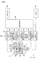
- Fig. 1 is an overall configuration diagram which shows a schematic configuration of a microscope system including an automatic focus detection device according to a first embodiment of the present invention.
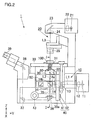
- Fig. 2 is a configuration diagram which shows a schematic configuration of an optical microscope including the automatic focus detection device according to the first embodiment of the present invention.
- Fig. 3 is a cross-sectional view taken along line I-I in Fig. 2.
- Fig. 4 is a partial enlarged cross-sectional view of a dark
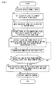
field illumination device 60 shown in Fig. 3. - Fig. 5 is a flowchart which shows focus detection processing employed in the automatic focus detection device according to the first embodiment of the present invention.
- Fig. 6 is a configuration diagram which shows a schematic configuration of an optical microscope including an automatic focus detection device according to a second embodiment of the present invention.
- Fig. 7 is a flowchart which shows focus detection processing employed in the automatic focus detection device according to the second embodiment of the present invention.
- Fig. 8 is a diagram which shows a modification of the AF dark
field illumination device 60 according to the embodiment of the present invention. - Fig. 9 is a diagram which shows a modification of the microscope system including the automatic focus detection device according to the embodiment of the present invention.
- Description will be made below regarding an automatic focus detection device according to an embodiment of the present invention and a microscope system employing the automatic focus detection device with reference to Figs. 1 through 9.
- A microscope system including an automatic focus detection device according to a first embodiment of the present invention will be explained referring to Fig. 1 through 4. Note that the devices are shown in Figs. 1 through 4 using the three-dimensional coordinate system.
- The microscope system comprises an
optical microscope 1 and an automatic focusing (which will also be abbreviated as "AF" hereafter)control system 80. - The
optical microscope 1 includes: an epifluorescence illumination device 10; a transmittedillumination device 20; aholding unit 30 for holding anobjective lens 31; astage 33 for mounting apetri dish 100 for storing an organism-originated tissue sample (hereafter referred to simply as "tissue sample"); aposition detection unit 40 for detecting the position of theholding unit 30 in the Z direction; adriving unit 43 for moving theholding unit 30 in the Z direction; an AF slit illumination/detection device 50; an AF darkfield illumination device 60; and aCCD camera 70. - The
AF control system 80 includes: amotor driving circuit 81; aposition detection circuit 82; an AF slitillumination driving circuit 83; a reflected-slit-light detection circuit 84; an AF dark fieldillumination control circuit 85; an imagecomparison computation circuit 86; acamera control circuit 87; and amicrocomputer 88 controlling theAF control system 80. Connected to themicrocomputer 88 is aninput unit 88a, through which the user can input data in theAF control system 80. Furthermore, adisplay 89 is connected to thecamera control circuit 87. - The
motor driving circuit 81 is electrically connected to a motor of thedriving unit 43 so as to control the motor. Theposition detection circuit 82 is electrically connected to a position sensor of theposition detection unit 40, thereby allowing detection of the position of theholding unit 30 along the Z axis. The AF slitillumination driving circuit 83 is electrically connected to an LED light source of the AF slit illumination/detection device 50, thereby allowing control of on/off actions and the illumination intensity of LED light source. The reflected-slit-light detection circuit 84 is electrically connected to a photo-sensor of the AF slit illumination/detection device 50, thereby allowing detection of the position of the reflected slit light on the photo-sensor. - The AF dark field
illumination control circuit 85 is electrically connected to an LED light source of the AF darkfield illumination device 60, thereby allowing control of on/off actions and the illumination intensity of the LED light source. The imagecomparison computation circuit 86 is electrically connected to an imaging device of theCCD camera 70, thereby allowing capturing images of the tissue sample at predetermined positions along the Z axis and implementing comparison/computation of the brightness (sharpness) of the captured images. Thecamera control circuit 87 controls the gain, the imaging timing, and so forth, for theCCD camera 70. - Explanation of the
optical microscope 1 will be made with reference to Fig. 2. - The epi
fluorescence illumination device 10 includes: amercury vapor lamp 11; acollector lens 12; afield lens 13; and afilter block 14 housing an excitation filter 14a and adichroic mirror 14b. The transmittedillumination device 20 includes: ahalogen lamp 21; acollector lens 22; amirror 23; afield lens 24; and acondenser lens 25. - The
objective lens 31 comprising a lens barrel an infinity optical system housed therein is mounted to anosepiece 32 fixed on theholding unit 30. Theholding unit 30 has aleg portion 30a extending in the negative Z direction. Theleg portion 30a is connected to thedriving unit 43, thereby allowing theleg portion 30a to be moved in the Z direction by actions of thedriving unit 43. With such a configuration, theobjective lens 31 is moved in the Z direction accompanying movement of theholding unit 30 in the Z direction. Thestage 33 can be moved in the X-Y directions, i.e., two-dimensional directions, and the focus detection for tissue sample is made by moving theobjective lens 31 in the Z direction. With the present embodiment, the position of theobjective lens 31 is measured in the Z direction by theposition detection unit 40. Theposition detection unit 40 consists of a linear scale 41 and a position sensor 42 fixed to theleg portion 30a. - Fig. 3 shows the AF slit illumination/
detection device 50 including: an LED light source 51 for emitting near-infrared light L4; acollector lens 52; aslit 53; and a dichroic mirror 55. Furthermore, theCCD camera 70 including animaging device 70a is mounted on the left portion (in the negative X direction) of theoptical microscope 1 through acylinder 71. The AF slit illumination/detection device 50 is the first focus detection device. - The AF dark
field illumination device 60 is held by asupport 61 fixed on theholding unit 30. Accordingly, the AF darkfield illumination device 60 is moved in the Z direction accompanying the movement of theholding unit 30 in the Z direction. The AF darkfield illumination device 60 is provided around the top end of the lens barrel of theobjective lens 31. The AF darkfield illumination device 60 is the second focus detection device. - Referring to the partial enlarged cross-sectional view shown in Fig. 4, the AF dark
field illumination device 60 comprises a pair of light-source components each of which includes anLED light source 63 for emitting infrared light L5 and acondenser lens 64. The pair of light-source components is symmetrically disposed in the direction with theobjective lens 31 introduced therebetween. Note that an LED light source for emitting near-infrared light may be employed as theLED light source 63. Electric power is supplied to eachLED light source 63 through apower cable 62. As shown in the drawing, each infrared light from eachLED light source 63 converges at a focal point of theobjective lens 31. - Alternatively, the AF dark
field illumination device 60 may have a configuration of an annular illumination system which emits the infrared light L5 to illuminate the tissue sample S. - In general, multiple
objective lenses 31, each of which has different focal distance, are mounted on thenosepiece 32 and the user can replace a desired objective lens on the optical path by turning thenosepiece 32. With the present embodiment, as stated above both thesupport 61 of the AF darkfield illumination device 60 and thenosepiece 32 are fixed on the holdingunit 30. This configuration allows the user to switch theobjective lens 31 while maintaining the converging position of the infrared light L5 at the focal point of theobjective lens 31. - Alternatively, the
optical microscope 1 may have another configuration in which the relation between the converging position of the infrared light L5 and the position of thepetri dish 100 can be maintained regardless switching of theobjective lens 31 and adjusting of the position of theobjective lens 31 in the Z direction (or the tissue sample S). - Returning to Fig. 2, description will be made regarding an illumination optical system, an observation optical system, and an AF optical system.
- In case of fluorescent observation, excitation light L1 having an wavelength in an ultraviolet region, which has been emitted from the
mercury vapor lamp 11, passes through thecollector lens 12 and thefield lens 13. Then, excitation light L1 enter the excitation filter 14a allowing the excitation light L1 having a predetermined wavelength region to pass through and enter the_dichroic mirror 14b. Thedichroic mirror 14b reflects the excitation light of a predetermined wavelength region inherent to thedichroic mirror 14b toward the Z direction. Thus, the reflected excitation light is introduced into theobjective lens 31 from below. The excitation light L1, which has passed through theobjective lens 31, passes through thebase 101 of thepetri dish 100, thereby illuminating the tissue sample S. The illumination of the excitation light L1 causes emission of fluorescence L2 from the portions stained with fluorescent dye in the tissue sample S. - The fluorescence L2, which has a longer wavelength than that of the excitation light L1, passes through the
base 101, and is introduced into theobjective lens 31. Then, the fluorescence L2 passes through thedichroic mirror 14b and animaging lens 34. The fluorescence L2, which has passes through theimaging lens 34, is split into two by ahalf prism 35. One part of the fluorescence L2 having a light quantity of 20% is introduced into aneyepiece 39 throughtotal reflection prisms mirror 38, thereby allowing the user to observe a fluorescent image. The other part of the fluorescence L2 having a light quantity of 80% passes in the negative X direction, and forms an image on theimaging device 70a of theCCD camera 70, thereby allowing capturing of the fluorescent image. - In transmissive observation, illumination light L3 emitted from the
halogen lamp 21 is collimated into a parallel light flux by thecollector lens 22. The illumination light L3 thus collimated is reflected by themirror 23, thereby being cast onto the tissue sample S from above thepetri dish 100 through thefield lens 24 and thecondenser lens 25. The transmitted light from the tissue sample S is introduced into theobjective lens 31 through thebase 101, and passes through the same optical path as with the fluorescence L2 described above, thereby allowing observation and capturing of an image of the tissue sample S. Note that a transmitted-light phase contrast microscope may employ an optical system in which the transmittedillumination device 20 is provided with a ring iris and theobjective lens 31 is provided with a phase ring is conjugated with the ring iris. - Next, description will be made regarding an optical system of the AF slit illumination/
detection device 50 and an optical system of the AF darkfield illumination device 60. - Referring to Fig. 3, the near-infrared light L4 emitted from the LED light source 51 of the AF slit illumination/
detection device 50 is converged to theslit 53 by thecollector lens 52. The near-infrared light L4 adjusted in the form of slit light passes through the converginglens 54, and is reflected by the dichroic mirror 55 in the Z direction. Then, the near-infrared light L4 thus reflected is incident onto thebase 101 of thepetri dish 100 through theobjective lens 31. Note that the slit light is split into two along the longitudinal center line. With such a configuration, one part of the slit light is shielded, and the other part thereof is used as illumination light. - Alternatively, the near-infrared light L4 employed in the present invention is not restricted to that in the form of slit light, rather an arrangement may be made employing the near-infrared light L4 in the form of spot light.
- The near-infrared light (reflected slit light) L4 reflected by the base 101 passes through the
objective lens 31, and is reflected by the dichroic mirror 55, thereby being introduced into a photo-sensor (not shown) included in the AF slit illumination/detection device 50. The photo-sensor is a line sensor or an area sensor having a plurality of pixels. The photo-sensor detects the incident position of the reflected slit light L4 on the photo-receptor face of the photo-sensor, which is dependent upon the reflection angle thereof. For example, in case that the reflected slit light L4 is incident on the center of the photo-receptor face of the photo-sensor, determination is made that thebase 101 is positioned at the focal point of theobjective lens 31, i.e., theobjective lens 31 is in focus condition. The photo-sensor outputs detection results with regard to the incident position of the slit light on the photo-receptor face to the reflected-slit-light detection circuit 84. At the same time, the position sensor 42 of theposition detection unit 40 outputs the position information to theposition detection circuit 82, which indicates the position of theobjective lens 31 in the Z direction. Thus, the detection results of the reflected slit light L4 is correlated with the position of theobjective lens 31 along the Z axis. - Note that there are two types of reflected light in the reflected slit light L4. One is the first reflected light which is reflected by the outer face P1 of the
base 101. The other is the second reflected light which is reflected by the inner face P2. Description will be made later regarding detection of these two types of reflected light. - The
LED light source 63 of the AF darkfield illumination device 60 is supplied with electric power through thepower cable 62, thereby emitting the infrared light L5. The infrared light L5 emitted from the LEDlight source 63 is converged by the converginglens 64, and is incident onto the tissue sample S in thepetri dish 100 with an oblique angle. The infrared light L5 incident onto the tissue sample S causes scattered light L6 therefrom. A part of the scattered light L6 passes through theobjective lens 31, and is introduced into theimaging lens 34 through the dichroic mirror 55 and thefilter block 14, thereby forming an image. Referring to Fig. 3, the scattered light L6 reflected by thehalf prism 35 passes through in the negative X direction, thereby allowing theimaging device 70a of theCCD camera 70 to capture a dark field microscopic image. Such illumination for obtaining a dark field image of the sample will be referred to as "dark field illumination". - The dark field microscopic images thus obtained exhibit different sharpness depending upon the position of the
objective lens 31 in the Z direction. It is needless to say that theobjective lens 31 in focus condition yields the sharpest dark field microscopic image. The brightness signals from the pixels of theimaging device 70a are compared while changing the position of theobjective lens 31 along the Z axis and capturing a dark field microscopic image at each position, thereby determining which microscopic image manifests the maximum sharpness(brightness)s, for example. With the present embodiment, the dark field microscopic image data is transmitted from theimaging device 70a of theCCD camera 70 to the imagecomparison computation circuit 86. At the same time, the position information regarding the position of theobjective lens 31 along the Z axis is transmitted from the position sensor 42 of theposition detection unit 40 to theposition detection circuit 82. Thus, the sharpness of the microscopic image formed by the brightness signal of each pixel is correlated with the position of theobjective lens 31 along the Z axis. - Explanation of an algorithm employed in the
AF control system 80 according to the present embodiment will be made with reference to Fig. 5. - Fig. 5 is a flowchart which shows focus detection processing employed in the automatic focus detection device according to the first embodiment. Upon the user pressing a start button (not shown) of the
input unit 88a, a start signal is transmitted to the AF slit illumination/detection device 50. Upon reception of the start signal, the AF slit illumination/detection device 50 enters the operating state, thereby starting AF adjustment operation. - First, the flow proceeds to Step S1 where the origin position of the
objective lens 31 is detected in the Z direction. Then, the flow proceeds to Step S2 where theobjective lens 31 is moved to the standby position at a high speed. Positioning theobjective lens 31 at the standby position ensures that theobjective lens 31 does not come in contact with thebase 101 of thepetri dish 100 in a sure manner. Subsequently, the flow proceeds to Step S3 where theobjective lens 31 is moved in the positive Z direction at a medium speed. - Then, the flow proceeds to Step S4 where determination is made whether or not the first reflected light is detected. The first reflected light is slit light L4 reflected from the outer face P1 of the
base 101 of thepetri dish 100. In the event that determination has been made that the first reflected light is not detected, the flow proceeds to Step S5. In Step S5, determination is made whether or not theobjective lens 31 is within a predetermined movable range thereof along the Z axis. In the event that determination has been made that theobjective lens 31 is out of the movable range thereof, the flow proceeds to Step S6. In Step S6, theobjective lens 31 is stopped, an error indication is displayed, and the processing ends. - On the other hand, in Step S5, in the event that determination has been made that the objective lens is within the movable range thereof along the Z axis, the flow returns to Step S3 where the objective lens is further moved in the positive Z direction.
- On the other hand, in Step S4, in the event that determination has been made that the first reflected light is detected, the flow proceeds to Step S7 where the
objective lens 31 is further moved in the positive Z direction at a fine pitch in the fine adjustment mode. Movement of theobjective lens 31 in the fine adjustment mode is limited to a certain distance determined with a reference position thereof at which the first reflected light has been detected, giving consideration to the thickness of thebase 101 of thepetri dish 100. Let us say that the movement of theobjective lens 31 in the fine adjustment mode is limited to 0.5 mm, for example. In Step S8, determination is made whether or not the movement of theobjective lens 31 is less than 0.5 mm. In the event that determination has been made that the movement of theobjective lens 31 is not less than 0.5 mm, i.e., in the event that the second reflected light has not been detected over a range equal to or greater than 0.5 mm, the focus detection processing using reflected-slit-light detection is cancelled, and the flow proceeds to Step S15 where the focus detection processing is switched to that using the AF darkfield illumination device 60. Note thatpetri dishes 100 formed of plastic or the like, for example, having an inner face P2 of the base 101 with poor planarity, often leads to such a situation. The processing following Step S15 will be explained later. - In Step S9, determination is made whether or not the second reflected light is detected. The second reflected light is the slit light L4 reflected from the inner face P2 of the
base 101 of thepetri dish 100. In the event that determination has been made that the second reflected light is not detected, the flow returns to Step S7 where theobjective lens 31 is further moved in the positive Z direction. On the other hand, in Step S9, in the event that determination has been made that the second reflected light is detected, the flow proceeds to Step S10 where theobjective lens 31 is further moved in the positive Z direction. In Step S11, determination is made whether or not theobjective lens 31 is focused on the inner face P2 of thebase 101. In the event that determination has been made that theobjective lens 31 is out of focus, the flow returns to Step S10. On the other hand, in Step S11, in the event that determination has been made that theobjective lens 31 is in focus, the flow proceeds to Step S12 where theobjective lens 31 is stopped. Then, the flow proceeds to Step S13 where the position of theobjective lens 31 in focus is stored. Subsequently, the flow proceeds to Step S14 where the epifluorescence illumination device 10 or the transmittedillumination device 20 started up, thereby capturing a microscopic image. - The above description has been made regarding the focus detection processing using the AFslit illumination/
detection device 50 alone. As described above, in some cases, such an arrangement leads to a situation that the flow proceeds from Step S8 to Step S15 due to irregularities of the inner face P2 of thebase 101 of thepetri dish 100. - Description will be made regarding focus detection processing using the AF dark
field illumination device 60. In Step S15, the AF darkfield illumination device 60 enters the operating state. Then, the flow proceeds to Step S16 where the CCD camera captures a dark field image as well as storing the position of theobjective lens 31. Then, the flow proceeds to Step S17 where theobjective lens 31 is repeatedly moved at a predetermined pitch so that a dark field image is captured and the position of theobjective lens 31 is stored for each position. - Then, the flow proceeds to Step S18 where comparison computation is performed for the dark field images each time that a dark field image is captured while moving the
objective lens 31. With such comparison computation according to the present embodiment, the brightness may be compared at pixels in each predetermined area of respective dark field images thus captured, i.e., difference in the brightness may be computed between the dark field images. Alternatively an arrangement may be made in which difference in the contrast is computed for and compared between the dark field images. - Subsequently, the flow proceeds to Step S19 where determination is made whether or not the
objective lens 31 reaches the end of the predetermined movable range. In the event that determination has been made that theobjective lens 31 does not reach the end of the predetermined movable range, the flow returns to Step S17 where theobjective lens 31 is further moved in the positive Z direction. On the other hand, in Step S19, in the event that determination has been made that theobjective lens 31 reaches the end of the predetermined movable range, the flow proceeds to Step S20. In Step S20, theobjective lens 31 is moved to the position at which the dark field image has exhibited the maximum brightness along the Z axis. Subsequently, the flow proceeds to Step S21 where the epifluorescence illumination device 10 or the transmittedillumination device 20 is started up, thereby capturing a microscopic image. - The focus detection using the AF dark
field illumination device 60 as described above has the advantage as follows. That is to say, such focus detection has the advantage of allowing adjustment of theobjective lens 31 so as to be focused on the organic sample S which is to be observed, regardless of irregularities of thebase 101 of thepetri dish 100. In other words, the focus detection using the AF darkfield illumination device 60 allows the user to adjust theobject lens 31 to be in focus using neither reflection from the inner face P1 of thebase 101 of thepetri dish 100 nor reflection from the outer face P2 thereof. Furthermore, with such focus detection, infrared light having small energy is cast onto the tissue sample S as illumination light, thereby allowing illumination of the tissue sample S without damage to the tissue sample S or fading of fluorescent dye. - Furthermore, the focus detection using both the AF slit illumination/
detection device 50 and the AF darkfield illumination device 60 has the advantage as follow. With such an arrangement, in the first stage, focus detection is made using the reflected-slit-light detection method which has the advantage of short processing time from detection up to computation of the focus position of theobjective lens 31. In the second stage, focus detection is made using the AF darkfield illumination device 60. Such an arrangement has the advantage of short processing time for focus detection in various situations. For example, let us say that the tissue sample S is placed on a slide plate with high planarity. In this case, focus detection is completed in the first stage alone, i.e., focus detection is made using the AF slit illumination/detection device 50 alone. This enables focus detection in short processing time. - A microscopic system according to the present embodiment includes an
optical microscope 1A and an AF control system for controlling an automatic focus detection device. Fig. 6 is a configuration diagram which shows a schematic configuration of theoptical microscope 1A including the automatic focus detection device according to the second embodiment. Fig. 7 is a flowchart which shows focus detection processing employed in the automatic focus detection device according to the second embodiment. - The
optical microscope 1A has the same configuration as that of the optical microscope 1 (see Fig. 2) described in the first embodiment, except for omission of the AF slit illumination/detection device 50. Accordingly, the AF control system according to the present embodiment has the same configuration as that of theAF control system 80 shown in Fig. 1, except for omission of the AF slitillumination driving circuit 83 and the reflected-slit-light detection circuit 84. Note that the same components are denoted by the same reference numerals, and description thereof will be omitted. - With the automatic focus detection device according to the present embodiment, focus detection is made using the AF dark
field illumination device 60 alone. The processing for the focus detection according to the present embodiment is generally the same as that using the AF darkfield illumination device 60 according to the first embodiment. - Description will be made below with reference to the flowchart shown in Fig. 7. Upon the user pressing a start button (not shown) of the
input unit 88a, a start signal is transmitted to the AF darkfield illumination device 60. Upon reception of the start signal, the AF darkfield illumination device 60 enters the operating state, thereby starting AF adjustment operation. First, the flow proceeds to Step S1 where the origin position of theobjective lens 31 is detected in the Z direction. Then, the flow proceeds to Step S2 where theobjective lens 31 is moved to the standby position at a high speed. Subsequently, the flow proceeds to Step S3 where theobjective lens 31 is moved in the positive Z direction at a medium speed. With the first embodiment, the same processing is performed by the AF slit illumination/detection device 50 for detection of reflected slit light. On the other hand, with the present embodiment, the aforementioned processing is performed for moving theobjective lens 31 to the first position at which a dark field image is to be captured by the CCD camera. - The automatic focus detection device according to the present embodiment has the same advantage as that of the AF dark
field illumination device 60 of the automatic focus detection device according to the first embodiment. Furthermore, with the automatic focus detection device according to the present embodiment, focus detection is made using the AF darkfield illumination device 60 alone, thereby enabling the size of theoptical microscope 1A to be reduced, as well as realizing a simple algorithm for focus detection. - Description will be made regarding a modification of the AF dark
field illumination device 60 having another configuration with reference to Fig. 8. Fig. 8 shows a modification according to the present embodiment, and specifically, is a partial enlarged cross-sectional view which shows an AF darkfield illumination device 160. Thenosepiece 32 for mounting theobjective lens 31 is fixed on the holdingunit 130. The AF darkfield illumination device 160 has a configuration of an epi illumination system for casting the infrared light L5 onto the tissue sample S along the optical axis in the Z direction. The epi illumination system comprises a first-stage optical system included within the holdingunit 130 and a second-stage optical system disposed around the lens barrel of theobjective lens 31. - The first-stage optical system includes: an LED
light source 161 for emitting infrared light; a converginglens 162; acollimator lens 163; aslit plate 164 on which a ring-shaped slit is formed; and a doughnut-shaped or a ring-shapedtotal reflection mirror 165. The second-stage optical system includes atotal reflection mirror 166 alone. The infrared light L5 emitted from the LEDlight source 161 is converged by the converginglens 162 and the infrared light L5 thus converged is collimated into a parallel light flux by thecollimator lens 163. Then the infrared light L5 with an annular cross-sectional shape is formed by theslit plate 164 and is reflected by thetotal reflection mirror 165 in the Z direction to pass through the outer space around the perimeter of the lens barrel of theobjective lens 31. Then, the infrared light L5 thus introduced is reflected by thetotal reflection mirror 166 disposed around the end of the lens barrel of theobjective lens 31 toward the sample S, thereby obtaining annular illumination. In the epi illumination system employed in the AF darkfield illumination device 160 according to the present embodiment, spot illumination as shown in Fig. 4 can be used in lieu of annular illumination. - With the AF dark
field illumination device 160 employing the epi illumination system, the AF dark field illumination device can be arranged at the desired space within theoptical microscope field illumination device 160 is disposed between theobjective lens 31 and the epifluorescence illumination device 10 as shown in Fig. 8. Instead, the microscope system may be designed with a different layout from that shown in Fig. 8. For example, the AF darkfield illumination device 160 may be disposed underneath the epifluorescence illumination device 10. - With an arrangement in which the automatic focus detection device includes the AF slit illumination/
detection device 50 and the AF darkfield illumination device 160, an arrangement may be made in which the AF slit illumination/detection device 50 and the AF darkfield illumination device 160 are disposed at the same level along the Z axis or opposite to one another with the same illumination optical axis. In order to provide such an arrangement, for example, the AF slit illumination/detection device 50 and the AF darkfield illumination device 160 are disposed. The near-infrared light L4 emitted from the LED light source 51 of the AF slit illumination/detection device 50 passes through in the positive X direction and the infrared light L5 emitted from the AF darkfield illumination device 160 passes through in the negative X direction. In addition to this design, the dichroic mirrior 55 of the AF slit illumination/detection device 50 may be disposed on the inner side of the doughnut-shapedtotal reflection mirror 165. - With such a layout, the AF slit illumination/
detection device 50 and the AF darkfield illumination device 160 are not disposed serially in the Z direction, and are disposed with generally the same height. This enables design of the optical microscope with a reduced length (height) in the Z direction. - Description will be made regarding a modification of a microscope system having another configuration with reference to Fig. 9. The microscope system as shown in Fig. 9 comprises a
PC 90 instead of themicrocomputer 88 of the microscope system according to the first embodiment shown in Fig. 1. ThePC 90 comprises an unshown input unit and adisplay 91 and centrally implements a focus detection algorithm employed in theAF control system 80. With such an arrangement, the microscope system simply has the same advantage as that of the microscope system according to the first embodiment by connecting a commercially-available PC 90 to theAF control system 80. Also, such a modification may be applied to the second embodiment, thereby having the same advantage as stated above. - While description has been made regarding a device having a function of automatic focus adjustment, the dark
field illumination device field illumination device objective lens 31, thereby converting the received light into electric signals by the photo-sensor. Note that the magnitude of the electric signal is proportional to the intensity of the scattered light L6 thus received. The intensity of the received light is measuredwhile changing the distance between the organism sample and theobjective lens 31, so that the focal point at which theobjective lens 31 is in focus on the organism sample can be found, since the received light thereat exhibits the maximum intensity. Upon detection of the maximum intensity of the scattered light L6 thus received, focus-detection processing ends. - Note that such a focus detection device has no need to capture an image formed of the scattered light L6. Accordingly, an arrangement may be made in which the
CCD camera 70 according to the aforementioned embodiments is replaced with such a photo-sensor having a smaller number of pixels, whose detection signal allows computation of the focus position. - Note that the present invention is not restricted to any arrangement described in the aforementioned embodiments; rather, various arrangements and modifications may be made without departing from the features of the present invention.
Claims (8)
- An automatic focus detection device comprising:an illumination light means (63) for emitting infrared or near-infrared light;a dark field illumination means (60) for casting illumination light emitted from the illumination light source (63) onto a sample stored in a container (100);an image-capturing means (70) for capturing a dark field image of the sample through an objective lens (31);an adjustment means (43) for adjusting a distance between the sample and the objective lens;a position detection means (40) for detecting the distance between the sample and the objective lens (31);a storage means (88) for storing the plurality of detected distances between the sample and the objective lens (31) as position information; anda computation means (88) for comparing a plurality of brightness signals of a predetermined number of dark field images each captured while changing the distance between the sample and the objective lens (31) by the adjustment device (43) and determining a specific dark field image having a maximum brightness signal, whereinthe focus position, at which the objective lens (31) is in focus on the sample, is detected based upon position information corresponding to a position, at which the maximum brightness of the dark field image is determined by the computation device (88), among a plurality of positions stored in the storage device (88) as the position information.
- An automatic focus detection device comprising:a first automatic focus detection device (60) according to Claim 1;a second automatic focus detection means (50) for casting illumination light onto the base of the container (100) storing the sample through the objective lens (31) and detecting light reflected from the base through the objective lens (31) by receiving the reflected light on a photo sensor (50), thereby detecting the focus position, at which the objective lens (31) is in focus on the sample, based upon the position at which the photo sensor receives the reflected light;a determination means (88) for determining whether or not the photo sensor (50) have received the reflected light; anda switching means (88) for switching a focus detection by the second automatic focus detection device (50) to the first automatic focus detection device (60) in the event that the determination device determines that the reflected light is not detected by the photo sensor (50).
- An automatic focus detection device according to Claim 1 or 2, wherein:the dark field illumination means (60) is disposed around the perimeter of an end of a lens barrel of the objective lens (31).
- An automatic focus detection device according to Claim 1 or 2, wherein:the dark field illumination means (160) comprises an epi illumination system in which a part of an optical path of the epi illumination system is parallel to an optical axis of the objective lens (31).
- An automatic focus detection device according to Claim 3 or 4, wherein
the dark field illumination means (160) comprises an annular illumination system including a light source (161) disposed outer the lens barrel and an annual-shaped total reflection mirror (165) disposed inner the lens barrel and reflecting light emitted from the light source (31) as an annual-shaped light in a direction of the axis of the objective lens (31). - A microscope system comprising:an automatic focus detection device (80) according to Claim 3 of 4,an epi fluorescence illumination means (10) for emitting excitation light onto the sample so as to cause emission of fluorescence, andthe objective lens (31) forming a fluorescence microscopic image of the sample, whereinthe annual-shaped total reflection mirror (165) is disposed between the objective lens (31) and the epi fluorescence illumination device (10).
- A microscope system comprising:an automatic focus detection device (80) according to Claim 3 or 4;an epi fluorescence illumination means (10) for emitting excitation light onto the sample so as to cause emission of fluorescence, andthe objective lens (31) forming a fluorescence microscopic image of the sample, whereinthe epi fluorescence illumination means (10) is disposed between the objective lens (31) and the annual-shaped total reflection mirror (165).
- A focus detection device comprising:an illumination light means (63) for emitting infrared or near-infrared light;a dark field illumination means (60) for casting illumination light, which has been emitted from the illumination light source (63), onto a sample;a photoelectric conversion means (70a) for detecting scattered light scattered from the sample through an objective lens (31); anda computation means (88) for computing a focus position, at which the objective lens (31) is in focus on the sample, based upon electric signals converted by the photoelectric conversion means (70a).
Applications Claiming Priority (1)
| Application Number | Priority Date | Filing Date | Title |
|---|---|---|---|
| JP2004240850A JP4599941B2 (en) | 2004-08-20 | 2004-08-20 | Automatic focus detection apparatus and microscope system including the same |
Publications (2)
| Publication Number | Publication Date |
|---|---|
| EP1628153A2 true EP1628153A2 (en) | 2006-02-22 |
| EP1628153A3 EP1628153A3 (en) | 2009-12-23 |
Family
ID=35462526
Family Applications (1)
| Application Number | Title | Priority Date | Filing Date |
|---|---|---|---|
| EP05107628A Withdrawn EP1628153A3 (en) | 2004-08-20 | 2005-08-19 | Automatic focus detection device and microscope system having the same |
Country Status (3)
| Country | Link |
|---|---|
| US (1) | US7843634B2 (en) |
| EP (1) | EP1628153A3 (en) |
| JP (1) | JP4599941B2 (en) |
Cited By (5)
| Publication number | Priority date | Publication date | Assignee | Title |
|---|---|---|---|---|
| WO2007054396A1 (en) * | 2005-10-05 | 2007-05-18 | Vistec Semiconductor Systems Gmbh | Dark field objective for a microscope |
| EP2239613A1 (en) * | 2009-04-08 | 2010-10-13 | Photonic Optische Geräte Ges.m.b.H. & Co.KG | Illumination device |
| CN111272771A (en) * | 2020-03-03 | 2020-06-12 | 中国科学院光电技术研究所 | High-resolution particle detection device |
| US10866526B2 (en) | 2017-09-28 | 2020-12-15 | Asml Holding N.V. | Metrology method and device |
| CN114994896A (en) * | 2022-06-08 | 2022-09-02 | 合肥埃科光电科技股份有限公司 | Microscope automatic focusing system and focusing method for micro-nano step samples |
Families Citing this family (18)
| Publication number | Priority date | Publication date | Assignee | Title |
|---|---|---|---|---|
| JP2006162765A (en) * | 2004-12-03 | 2006-06-22 | Keyence Corp | Inverted type fluorescence microscope |
| EP2028264A4 (en) * | 2006-06-15 | 2012-10-24 | Nikon Corp | Cell incubator |
| JP4663602B2 (en) | 2006-08-14 | 2011-04-06 | オリンパス株式会社 | Automatic focusing device, microscope and automatic focusing method |
| DE102008018952B4 (en) * | 2008-04-15 | 2021-01-14 | Carl Zeiss Microscopy Gmbh | Microscope with hold focus control |
| JP2010008492A (en) * | 2008-06-24 | 2010-01-14 | Olympus Corp | Living sample observation apparatus |
| JP5095663B2 (en) * | 2009-03-31 | 2012-12-12 | 独立行政法人科学技術振興機構 | Fluorescence microscope, fluorescence observation method |
| JP5374266B2 (en) * | 2009-07-22 | 2013-12-25 | 株式会社シロク | Optical position detector |
| JP5338573B2 (en) | 2009-08-31 | 2013-11-13 | ソニー株式会社 | Fluorescent image acquisition method, fluorescent image acquisition device, and fluorescent image acquisition program |
| JP6108772B2 (en) * | 2012-11-05 | 2017-04-05 | オリンパス株式会社 | Microscope and dark field objective lens |
| JP6387589B2 (en) | 2013-08-30 | 2018-09-12 | 株式会社リコー | Image forming apparatus, vehicle, and control method of image forming apparatus |
| US9804029B2 (en) * | 2014-03-05 | 2017-10-31 | Hitachi High-Technologies Corporation | Microspectroscopy device |
| ES2599056B2 (en) * | 2015-07-31 | 2017-07-07 | Pablo ALBERTOS SÁNCHEZ | Device for testing a sample of cells |
| JP6635125B2 (en) * | 2015-11-27 | 2020-01-22 | 株式会社ニコン | Microscope, observation method, and image processing program |
| US10324041B2 (en) | 2016-12-21 | 2019-06-18 | Abbott Japan Co., Ltd. | Optical imaging system using lateral illumination for digital assays |
| US11047854B2 (en) | 2017-02-06 | 2021-06-29 | Abbott Japan Llc | Methods for reducing noise in signal-generating digital assays |
| CN117891042A (en) * | 2023-01-06 | 2024-04-16 | 深圳市真迈生物科技有限公司 | A focusing method, optical imaging system, sequencing system and medium |
| CN120102557A (en) * | 2023-12-06 | 2025-06-06 | 深圳市真迈生物科技有限公司 | Imaging method, system and storage medium |
| WO2025001146A1 (en) * | 2024-02-04 | 2025-01-02 | 苏州丰泰医疗科技有限公司 | High-precision microscopic scanner |
Citations (1)
| Publication number | Priority date | Publication date | Assignee | Title |
|---|---|---|---|---|
| US6674574B1 (en) * | 1999-09-24 | 2004-01-06 | Olympus Corporation | Focusing system for a microscope and a reflected illumination fluorescence microscope using the focusing system |
Family Cites Families (28)
| Publication number | Priority date | Publication date | Assignee | Title |
|---|---|---|---|---|
| JPS6026311A (en) * | 1983-07-22 | 1985-02-09 | Nippon Kogaku Kk <Nikon> | Focus detection device for dark field microscope |
| DE3527322A1 (en) * | 1985-07-31 | 1987-02-12 | Zeiss Carl Fa | AUTOFOCUS DEVICE FOR LIGHTING MICROSCOPE |
| JPH0792437B2 (en) * | 1986-12-05 | 1995-10-09 | 日本電気株式会社 | Surface shape observation device |
| DE3828381C2 (en) | 1988-08-20 | 1997-09-11 | Zeiss Carl Fa | Method and device for automatically focusing an optical system |
| JPH05210052A (en) * | 1991-02-27 | 1993-08-20 | Hitachi Ltd | Device and method for irradiation with laser beam through microscope |
| EP0501688A1 (en) * | 1991-02-27 | 1992-09-02 | Hitachi, Ltd. | Apparatus and method for applying a laser beam through a microscope |
| US5578832A (en) * | 1994-09-02 | 1996-11-26 | Affymetrix, Inc. | Method and apparatus for imaging a sample on a device |
| JP3439259B2 (en) | 1994-05-25 | 2003-08-25 | オリンパス光学工業株式会社 | Automatic focus detection device |
| JPH102860A (en) * | 1996-06-17 | 1998-01-06 | Olympus Optical Co Ltd | Micro-substance inspection lens device |
| JP3861357B2 (en) * | 1997-03-10 | 2006-12-20 | 株式会社ニコン | Microscope revolver and microscope integrated with optical device |
| JPH10268205A (en) * | 1997-03-24 | 1998-10-09 | Olympus Optical Co Ltd | Member for dark field illumination |
| JP4531895B2 (en) * | 1999-12-06 | 2010-08-25 | オリンパス株式会社 | Laser focusing optical system and laser scanning microscope using the same |
| US7095904B2 (en) | 2000-04-12 | 2006-08-22 | Ultratech, Inc. | Method and apparatus for determining best focus using dark-field imaging |
| JP4519987B2 (en) | 2000-04-13 | 2010-08-04 | オリンパス株式会社 | Focus detection device |
| US6906858B2 (en) * | 2000-07-17 | 2005-06-14 | Olympus Optical Co., Ltd. | Microscope provided with an objective lens focusing apparatus and an objective lens switching apparatus |
| US7456028B2 (en) * | 2000-10-16 | 2008-11-25 | Board Of Trustees Of The University Of Arkansas, N.A. | Electrochemical method for detecting water born pathogens |
| JP2003042720A (en) * | 2001-07-27 | 2003-02-13 | Olympus Optical Co Ltd | Height measuring apparatus |
| JP4610798B2 (en) | 2001-06-19 | 2011-01-12 | エスアイアイ・ナノテクノロジー株式会社 | Scanning electron microscope with laser defect detection function and its autofocus method |
| JP4878708B2 (en) * | 2001-08-08 | 2012-02-15 | オリンパス株式会社 | Confocal scanning microscope, alignment method thereof, program, and storage medium |
| JP4021183B2 (en) * | 2001-11-29 | 2007-12-12 | オリンパス株式会社 | Focus state signal output device |
| JP2003270524A (en) * | 2002-03-19 | 2003-09-25 | Nikon Corp | Focus detection device, microscope equipped with the same, and focus detection method |
| JP2003279857A (en) * | 2002-03-20 | 2003-10-02 | Olympus Optical Co Ltd | Laser microscope |
| JP2004013071A (en) | 2002-06-11 | 2004-01-15 | Nikon Corp | Slit projection type autofocus device |
| JP4370554B2 (en) * | 2002-06-14 | 2009-11-25 | 株式会社ニコン | Autofocus device and microscope with autofocus |
| JP3896924B2 (en) * | 2002-08-07 | 2007-03-22 | 松下電器産業株式会社 | Biological sample observation apparatus and observation method |
| JP2004101406A (en) * | 2002-09-11 | 2004-04-02 | Tokyo Seimitsu Co Ltd | Visual inspection device |
| JP4171974B2 (en) * | 2003-01-29 | 2008-10-29 | 富士電機ホールディングス株式会社 | Antigen separation apparatus and antigen measurement method and apparatus using the same |
| WO2005057193A1 (en) * | 2003-11-18 | 2005-06-23 | Applied Materials Israel, Ltd | Inspection system with auto-focus |
-
2004
- 2004-08-20 JP JP2004240850A patent/JP4599941B2/en not_active Expired - Fee Related
-
2005
- 2005-08-19 US US11/206,930 patent/US7843634B2/en not_active Expired - Fee Related
- 2005-08-19 EP EP05107628A patent/EP1628153A3/en not_active Withdrawn
Patent Citations (1)
| Publication number | Priority date | Publication date | Assignee | Title |
|---|---|---|---|---|
| US6674574B1 (en) * | 1999-09-24 | 2004-01-06 | Olympus Corporation | Focusing system for a microscope and a reflected illumination fluorescence microscope using the focusing system |
Cited By (7)
| Publication number | Priority date | Publication date | Assignee | Title |
|---|---|---|---|---|
| WO2007054396A1 (en) * | 2005-10-05 | 2007-05-18 | Vistec Semiconductor Systems Gmbh | Dark field objective for a microscope |
| EP2239613A1 (en) * | 2009-04-08 | 2010-10-13 | Photonic Optische Geräte Ges.m.b.H. & Co.KG | Illumination device |
| US10866526B2 (en) | 2017-09-28 | 2020-12-15 | Asml Holding N.V. | Metrology method and device |
| CN111272771A (en) * | 2020-03-03 | 2020-06-12 | 中国科学院光电技术研究所 | High-resolution particle detection device |
| CN111272771B (en) * | 2020-03-03 | 2023-03-31 | 中国科学院光电技术研究所 | High-resolution particle detection device |
| CN114994896A (en) * | 2022-06-08 | 2022-09-02 | 合肥埃科光电科技股份有限公司 | Microscope automatic focusing system and focusing method for micro-nano step samples |
| CN114994896B (en) * | 2022-06-08 | 2024-05-10 | 合肥埃科光电科技股份有限公司 | Microscope automatic focusing system for micro-nano step sample and focusing method thereof |
Also Published As
| Publication number | Publication date |
|---|---|
| US20060039064A1 (en) | 2006-02-23 |
| JP2006058642A (en) | 2006-03-02 |
| EP1628153A3 (en) | 2009-12-23 |
| US7843634B2 (en) | 2010-11-30 |
| JP4599941B2 (en) | 2010-12-15 |
Similar Documents
| Publication | Publication Date | Title |
|---|---|---|
| US7843634B2 (en) | Automatic focus detection device and microscope system having the same | |
| US8040597B2 (en) | Illuminating device | |
| JP5875812B2 (en) | Microscope system and illumination intensity adjustment method | |
| US7304281B2 (en) | Confocal laser scanning microscope | |
| US9772540B2 (en) | Autofocus for imaging system | |
| JP6692660B2 (en) | Imaging device | |
| JPWO2011007768A1 (en) | Three-dimensional direction drift control device and microscope device | |
| JP4854880B2 (en) | Laser microscope | |
| JP5053691B2 (en) | Specimen scanner device and specimen position detection method using the device | |
| CN117269190A (en) | Wafer defect optical detection system | |
| JP2003167183A (en) | Focusing state signal outputting device | |
| JP6685148B2 (en) | Imaging device and imaging method | |
| CN107621692B (en) | Objective lens module and microscope | |
| JP2003307682A5 (en) | ||
| JP3349711B2 (en) | Automatic focus detection device | |
| JP4502104B2 (en) | Image pickup apparatus having compound prism optical system | |
| JP2004102032A (en) | Scanning type confocal microscope system | |
| JP2005250151A (en) | Microscope apparatus, light control method and light control program for the microscope apparatus | |
| JP3486754B2 (en) | Scanning optical microscope | |
| JP2010008458A (en) | Optical measuring instrument and pattern formed on projection plate | |
| US10782515B2 (en) | Microscope system, observation method, and computer-readable recording medium | |
| JP5307868B2 (en) | Total reflection microscope | |
| JP4963567B2 (en) | Minute height measuring device | |
| JP5145698B2 (en) | Microscope focus detection apparatus and microscope having the same | |
| KR100758837B1 (en) | Autofocus Microscope |
Legal Events
| Date | Code | Title | Description |
|---|---|---|---|
| PUAI | Public reference made under article 153(3) epc to a published international application that has entered the european phase |
Free format text: ORIGINAL CODE: 0009012 |
|
| AK | Designated contracting states |
Kind code of ref document: A2 Designated state(s): AT BE BG CH CY CZ DE DK EE ES FI FR GB GR HU IE IS IT LI LT LU LV MC NL PL PT RO SE SI SK TR |
|
| AX | Request for extension of the european patent |
Extension state: AL BA HR MK YU |
|
| PUAL | Search report despatched |
Free format text: ORIGINAL CODE: 0009013 |
|
| AK | Designated contracting states |
Kind code of ref document: A3 Designated state(s): AT BE BG CH CY CZ DE DK EE ES FI FR GB GR HU IE IS IT LI LT LU LV MC NL PL PT RO SE SI SK TR |
|
| AX | Request for extension of the european patent |
Extension state: AL BA HR MK YU |
|
| RAP1 | Party data changed (applicant data changed or rights of an application transferred) |
Owner name: NIKON CORPORATION |
|
| 17P | Request for examination filed |
Effective date: 20100623 |
|
| AKX | Designation fees paid |
Designated state(s): DE |
|
| 17Q | First examination report despatched |
Effective date: 20120119 |
|
| STAA | Information on the status of an ep patent application or granted ep patent |
Free format text: STATUS: THE APPLICATION IS DEEMED TO BE WITHDRAWN |
|
| 18D | Application deemed to be withdrawn |
Effective date: 20120731 |