JP4878708B2 - Confocal scanning microscope, alignment method thereof, program, and storage medium - Google Patents
Confocal scanning microscope, alignment method thereof, program, and storage medium Download PDFInfo
- Publication number
- JP4878708B2 JP4878708B2 JP2001241317A JP2001241317A JP4878708B2 JP 4878708 B2 JP4878708 B2 JP 4878708B2 JP 2001241317 A JP2001241317 A JP 2001241317A JP 2001241317 A JP2001241317 A JP 2001241317A JP 4878708 B2 JP4878708 B2 JP 4878708B2
- Authority
- JP
- Japan
- Prior art keywords
- objective lens
- observation
- observation target
- focus
- scanning microscope
- Prior art date
- Legal status (The legal status is an assumption and is not a legal conclusion. Google has not performed a legal analysis and makes no representation as to the accuracy of the status listed.)
- Expired - Fee Related
Links
Images


Description
【0001】
【発明の属する技術分野】
本発明は、共焦点走査型顕微鏡に関し、特に自動焦点検出機能を備えた共焦点走査型顕微鏡に関する。
【0002】
【従来の技術】
共焦点走査型顕微鏡は、点光源によって試料面の特定の観察対象部をピンポイントに照射しながら走査し、この試料面からの反射光のうちピンホールを通過した光のみを電気信号に変換して、この検出信号から試料面の光の濃淡情報を得るもので、更には焦点の合った位置の情報を深さ方向に複数得ることにより試料面の三次元情報を得ることが出来るようにしたものである。
【0003】
共焦点走査型顕微鏡は、レーザ光などの点光源と光検出器の前面に設けたピンホールを組み合わせ、試料面をピンポイントで照明すると共に、測定点以外からの散乱光をピンホールで抑制する。すなわち共焦点走査型顕微鏡では、測定点近傍からのノイズ光をピンホール周辺に結像させ、また、光軸方向にずれた面からの光を対物レンズによってピンホールの前で広げてピンホールで抑制する。これにより、測定点以外からの反射光をカットし、焦点が合った高さ位置の反射光のみを光電変換器によって変換して、三次元空間中の一点だけを測定できるようにしている。
【0004】
ところで、顕微鏡などで適用される自動焦点検出方法には、様々な方式のものが提案されている。
例えば、試料面での反射光を受光素子で検出して得た輝度データをコントラスト量として扱い、コントラスト量が最も高くなるようにステージまたは対物レンズをZ軸方向に移動させ合焦させる、いわゆる山登りサーボ方式によるオートフォーカス(以下、AFと略す)制御を行うものがある。
【0005】
図8は、このような山登りサーボ方式の自動焦点検出方法の一例を説明するものである。
まず、不図示の対物レンズをZ軸方向(光軸方向)で試料から離れる方向(図8中左方向)に第1ピッチ(同図中白丸印)で移動させながら試料面からの反射光の輝度データを得てゆき、輝度値がしきい値TH以上になるのを監視する。そしてしきい値THを越える輝度値を検出すると、今度は第1ピッチより細かい第2ピッチ(同図中黒三角)で、Z軸方向において輝度値が増す方向(同図中左方向)に対物レンズを移動させながら最高輝度値Hとなるのを監視する。そして、最高輝度値Hを検出した後も第2ピッチのままで同方向に対物レンズを移動させ、輝度値が最高輝度値Hの50%になる点Mを探し、その位置で対物レンズの移動を一時停止させる。
【0006】
次に、対物レンズの移動方向を反転させて(図8中右方向)、今度は、第2ピッチより細かい第3ピッチ(同図中白三角印)で最高輝度値Hとなる位置を通過するまで移動させる。そして輝度値が3回続けて直前に取り込んだ輝度値より小さい点を見つけたなら、真の最高輝度の合焦点を過ぎたものと判断して、最高輝度位置Fに対物レンズを移動させて合焦を完了する。
【0007】
【発明が解決しようとする課題】
共焦点走査型顕微鏡のAF制御においては、合焦点の位置の補足範囲は、対物レンズの倍率に影響される。
5倍乃至10倍程度の低倍率の対物レンズを用いる場合は、焦点深度が大きい為補足範囲は広く、また50倍以上の対物レンズを用いる場合は焦点深度が小さい為補足範囲は狭い。よって、高倍率の対物レンズで観察するときは、まず低倍率の対物レンズで大まかに合焦点位置を検出した後、高倍率の対物レンズで微調節して合焦点位置を求める。
【0008】
合焦点位置の検出においては、輝度値が飽和しない範囲内で輝度値の変化が大きいと検出しやすい。よって、観察対象部分の輝度値が低い場合、合焦点位置の検出は試料(面)の輝度が高い部分で行い、合焦点位置を検出した後に観察対象部を観察画像中央などの所望の位置へ移動するという作業を行うことが多い。そして高倍率の対物レンズで観察する時は、この合焦点位置の検出と観察対象部への移動という作業を低倍率の対物レンズと高倍率の対物レンズのそれぞれにおいて行うことになる。
【0009】
また、合焦点位置の検出に用いる位置にごみなどが存在した為にAF制御に失敗した場合、手動で検出位置を変更してから再びAF制御を行う必要がある。AF制御に失敗すると、実際に試料の観察を開始するまでにAF制御及び観察位置への移動の作業を繰り返すこととなるが、観察位置など所望の位置へ移動するのは、対物レンズの倍率が高いほど困難なので、非常に手間がかかる作業となる。
【0010】
更に、観察画像を用いた計測等、再現性が要求される場合には、合焦点位置を安定して検出したいので、一般的に合焦点位置の検出位置を一定にした方がよい。しかし、対物レンズの光軸は対物レンズ毎に誤差があるので、対物レンズを切り換えたときに検出位置が変わってしまうことがある。
【0011】
以上の問題を鑑み、本発明は、観察対象部で焦点の合った観察画像を容易に取得可能な共焦点走査型顕微鏡を提供することを課題とする。
また、観察画像を用いた計測での再現性を向上させた共焦点走査型顕微鏡を提供することを課題とする。
【0012】
【課題を解決するための手段】
本発明の態様のひとつである共焦点走査型顕微鏡は、オートフォーカス機能を備えた共焦点走査型顕微鏡において、第1の対物レンズによってオートフォーカスを実行して合焦点位置を検出する第1の合焦点検出手段と、前記第1の合焦点検出手段による合焦点位置の検出後、第1の観察対象部を決定するため観察試料の予め定められた位置を検索する第1の観察対象部検索手段と、前記第1の観察対象部検索手段による検索結果に基いて前記観察試料と前記第1の対物レンズとの相対位置を移動する第1の移動手段と、を備え、前記第1の観察対象部検索手段は、前記予め定められた位置から複数ライン分走査して得られた輝度データの平均値を求め、該平均値を用いて前記第1の観察対象部を決定することを特徴とするものである。
【0017】
また、本発明の別の態様のひとつである、共焦点走査型顕微鏡における位置合わせ方法は、オートフォーカス機能を備えた共焦点走査型顕微鏡における位置合わせ方法であって、第1の対物レンズによってオートフォーカスを実行して合焦点位置を検出し、前記合焦点位置の検出後、観察対象部を決定するため観察試料の予め定められた位置を検索し、前記検索結果に基いて前記観察試料と前記第1の対物レンズとの相対位置を移動させるものであり、前記検索では、前記予め定められた位置から複数ライン分走査して得られた輝度データの平均値を求め、該平均値を用いて前記観察対象部を決定することを特徴とするものである。
【0018】
なお、上述した本発明の各構成により行なわれる機能と同様の制御を情報処理装置に行なわせるプログラムを記憶した情報処理装置読み取り可能な記憶媒体から、そのプログラムを情報処理装置に読み出させて実行させることによっても、前述した課題を解決することができる。
【0019】
【発明の実施の形態】
以下、本発明の実施の形態を図面に基づいて説明する。
図1は、本実施形態における共焦点走査型顕微鏡のシステムの概略構成を示す図である。
【0020】
図1のシステム構成では、光源1、二次元走査用スキャナ2、対物レンズ3、ステージ5、光検出器6、A/D変換器7、移動駆動部8、CPU9、メモリ10、フレームメモリ11及び表示部12を備えている。尚CPU9、メモリ10、フレームメモリ11及び表示部12は、共焦点走査型顕微鏡とは別構成にし、共焦点走査型顕微鏡に接続されたパソコン等の汎用の情報処理装置とする構成としても良い。
【0021】
光源1は、レーザ光源などの点光源からなっている。この光源1からのスポット光は二次元走査用スキャナ2に導かれている。二次元走査用スキャナ2は、光源1から入射されたスポット光を試料4上に二次元走査する為のもので、例えばX軸方向走査用のXスキャナとしてガルバノミラー又はレゾナンドスキャナとY軸方向走査用のYスキャナとしてガルバノミラーを有し、これらXスキャナとYスキャナをX軸方向とY軸方向に振ることでスポット光を試料4上でXY軸方向(光軸に垂直な方向)に振る。
【0022】
対物レンズ3は、サーボモータなどの移動駆動部8によりスポット光の光軸方向、つまりZ軸方向に連続的に移動可能になっている。また二次元走査用スキャナ2によって二次元走査されたスポット光は、対物レンズ3を透過してステージ5上の試料4に照射される。そして試料4からの反射光は、対物レンズ3を通して二次元走査用スキャナ2に戻り、この二次元走査用スキャナ2から光検出器6に導かれる。
【0023】
ステージ5は、CPU9からの制御指示に基づいて、スポット光の光軸に対して垂直方向、つまりXY軸方向に試料4を移動する。
光検出器6は、受光面の前面に不図示のピンホールを有し、二次元走査用スキャナ2を通った反射光のうちこのピンホールを介して得られる光情報を受光し、その光量に対応した輝度信号を出力する。光検出器6は、A/D変換器7を介してCPU9に接続されており、輝度信号はデジタル値に変換されてCPU9に出力される。
【0024】
CPU9は、図1の各構成要素に制御指示を出して動作制御を行うもので、移動駆動部8に対しては対物レンズ3のZ軸方向の連続移動速度の設定、移動開始/停止の指示及び停止位置の読み込みなどを行う。また、二次元走査用スキャナ2に対しては、スポット光の走査を指示し、この走査により得られる光検出器6の輝度信号から共焦点観察像を生成する。そしてステージ5に対しては、試料4のXY方向の移動開始/停止指示などを行う。
【0025】
CPU9は、メモリ10上のプログラムに基づいて、輝度検出手段901及び合焦点判断手段902を実現する。輝度検出手段901は、対物レンズ3のZ軸方向の連続移動に伴い、所定のサンプリング周波数、例えば1KHzで光検出器6からの輝度信号を検出する。そして合焦点判断手段902は、この輝度検出手段901により検出された輝度値の変化から合焦点を判断する。またCPU9は、後述する観察像からの観察対象部の検索処理及び検索結果に基いたステージ5への位置の移動の指示を行う。
【0026】
メモリ10は、CPU9で実行されるプログラムを記憶したり、CPU9が処理を行う為のワークエリアとして用いられる。また、後述するCPU9が行う観察対象部の検索で、検索に使用される画像データや平均断面データなどを作成、記憶する際に使用される。
【0027】
表示部12は、光検出器6からの輝度データに基づいてCPU9が生成した観察画像を、フレームメモリ11を介して表示するものである。
次に上記構成による顕微鏡装置の本実施形態での観察時の処理動作について説明する。
【0028】
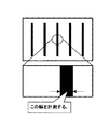
以下の説明では、観察試料として、図2に示すような輝度が高い部分と低い部分が連続するラインアンドスペース形状を観察する場合を例としている。この試料は、予め大まかに形状が判っており、輝度が高い部分の幅が約30μm、輝度が低い部分の幅が約5μmであるとする。そして本実施形態では、この試料の輝度が低い部分の線幅を観察する場合を例にして説明する。
【0029】
観察を開始するに際し、まず大まかな合焦点位置を検出する為、顕微鏡に低倍率の対物レンズを設定し、AF制御を実行する。このAFの実行位置には観察像の中央位置を用い、この位置での輝度値を使用してAFを実行するものとする。尚、本発明はAFの方式には依存しない。よって、ここで行うAFの方式は、上述した山登りサーボ方式等一般的に行われているどのような方式で行っても良いので、AFに対する詳細な説明は省略する。
【0030】
AFが失敗した場合、AFの再実行条件を満たすならばAFを実行する位置を移動して、AFが成功するか再実行条件を満たさなくなるまでAFの実行を繰り返す。この時、AFの再実行条件と失敗したときのAFの実行位置の移動量は試料の形状等から予め算出して設定しておく。例えば、AFの実行位置の移動を水平方向に左に10μm移動するものとし、再実行条件を輝度が高い範囲内のみ移動可能とすれば、AFは最大3回実行されることになる。
【0031】
低倍率の対物レンズでのAFが成功すると、次に観察対象部の検索を行う。
ここで観察対象部の検索について図3を用いて説明する。
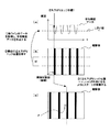
図3は、本実施形態による観察対象部の検索動作とステージの移動動作を説明する図である。
【0032】
まず、低倍率の対物レンズでAFが成功した位置で、試料4を走査し、走査画像を得る。そしてこの走査画像から画像の水平方向の中心付近の数ライン分の輝度データを取得する。このとき取得するライン数と取得位置は試料形状に合わせて予め設定しておく。図3では同図(b)のW部分から水平方向に数ライン分の輝度データを取得するものとする。
【0033】
次に取得した輝度データを、垂直方向で同じ位置の輝度値を加算平均して、図3(a)のような1ラインの平均輝度データを作成する。同図の場合、試料がラインアンドスペース形状なので、1ライン分の輝度データは輝度が高い部分と低い部分が同じ間隔で順番に繰り返される値となっている。本実施形態では、この平均輝度データを用いることによって、観察対象部にごみ等の異物が存在したり、ノイズのために検索が失敗するのを防止する。
【0034】
本実施形態では、輝度データの低い部分の幅を観察するので、作成した図3(a)のような平均輝度データから試料の輝度の高い部分と低い部分の境界であるエッジの位置を検索する。
ここでのエッジ位置とは、図3(a)の平均輝度データIを左側から(Xが大きくなる方向へ)検索した時に、あらかじめ設定しておいたしきい値Tiより輝度が小さくなる方向に初めて横切る位置(同図のE部分)とする。そしてこのエッジ位置を、観察対象部の検索結果とする。エッジ位置の検索に失敗したときは、観察位置を変更して再度AFの実行からやり直す。
【0035】
観察対象部の検索が成功した時は、検索したエッジの位置から微小量離れた位置(図3(c)のFの位置)がAFを実行する位置となるようにステージを移動する。観察対象部として検索されたエッジ位置は輝度が低くなる途中の位置であり、その位置でAFを行うと失敗する可能性が高いので、検索されたエッジ位置から予め定められた求め方で求まる位置、例えばエッジ位置より微小量(−αμm)離した位置をAFを実行する位置に設定する。尚、このエッジ位置から離す長さαの大きさは試料の形状やAFに使用する領域サイズ等から予め計算し、設定しておく。
【0036】
ステージの移動が完了したら、更に詳細な合焦点位置を検出する為に、観察に用いる高倍率の対物レンズに切り換える。このときの対物レンズの位置Zは、低倍率の対物レンズでAFが成功した位置から変化していない。そしてこの状態から高倍率の対物レンズを用いてAFを実行する。
【0037】
このAFが失敗した時は低倍率の対物レンズでAFを失敗した場合と同様、AFが成功するか再実行条件を満たさなくなるまで位置を移動してAFの実行を繰り返す。尚この時の移動量と再実行条件は高倍率対物レンズ用の設定とし、移動量は低倍率対物レンズでの値より通常小さくなる。
【0038】
AFが成功した時は、次に観察対象部の検索を行う。この検索方法は低倍率対物レンズの時と基本的には同様であるが、検索に失敗した時は、表示部12に表示される観察画像の水平方向の大きさ分右へステージを移動して再度検索する。そして再検索でも失敗した時は、観察位置を変更して、対物レンズを低倍率の対物レンズに切り換えてAFの実行からやり直す。
【0039】
観察対象部の検索が成功したときは、観察対象部が画像中央になるようにステージを移動する。これにより観察対象部が中央に位置しているので、そのまま観察像を取り込むと、所望の観察象が得られる。
このように本実施形態による共焦点走査型顕微鏡では、合焦点位置の検出位置が安定し、所望の画像を得るまでに手間がかからない。
【0040】
また合焦点位置が安定した画像が得られ、また共焦点走査型顕微鏡で計測精度が良い画像中央付近に常に計測対象部が位置するので、画像を用いた計測で再現性を向上する。
図4は、本実施形態における共焦点走査型顕微鏡による試料観察時の動作処理を示すフローチャートである。同図の処理は、CPU9がメモリ10内のプログラムに基いて共焦点走査型顕微鏡を制御して実現される。
【0041】
観察を開始するに際し、ステップS101としてまず大まかな合焦点位置を検出する為、低倍率の対物レンズを設定して、ステップS102としてAFを実行する。
ステップS102でのAFが失敗した場合(ステップS103、No)、予めメモリに設定記憶されているAFの再実行条件を満たすならば(ステップS121、Yes)、ステップS122としてAFを実行する位置を移動した後、ステップS102に処理を戻して再度AFを実行する。そして、再実行条件を満たす間は、ステップS102でAFが成功するまでステップS102、S103、S121及びS122の処理を繰り返す。
【0042】
ステップS102でのAFが成功すると(ステップS103、Yes)、次にステップS104として観察対象部の検索処理を行う。
図5は、ステップS104、S110及びS116で行われる観察対象部の検索処理を示すフローチャートである。
【0043】
本処理が呼び出されると、まず、走査画像から画像の水平方向の中心付近の予め定められている位置から数ライン分の輝度データを取得する(ステップS201)。
次にステップS201で取得した輝度データを、垂直方向において同じ位置の輝度値を加算平均して、1ラインの平均輝度データを作成する(ステップS202)。そして、ステップS203としてステップS202で作成した平均輝度データからエッジ位置を検索した後、検索処理を終了して処理を図3に戻す。
【0044】
ステップS104での検索の結果、エッジ位置を得ることが出来ず、観察対象部の検索に失敗したときは(ステップS105、No)、ステップS114として観察位置を移動して変更した後、処理をステップS102に戻し、別の観察位置で再度低倍率の対物レンズによるAFを実行する。
【0045】
ステップS104での観察対象部の検索が成功した場合は(ステップS105、Yes)、ステップS104で観察対象部から検索した位置を基にして予め定められた求め方で求まる位置をAFを実行する位置とし、その位置が観察画像の中央にくるようにステージを移動する(ステップS106)。
【0046】
ステージの移動が完了したら、詳細な合焦点位置を検出する為に、実際に観測に用いる高倍率の対物レンズに切り替え(ステップS107)、AFを実行する(ステップS108)。
ステップS108でAFが失敗した時は(ステップS109、No)、低倍率の対物レンズでのAF失敗と同様、予めメモリに設定記憶されている高倍率の対物レンズ用のAFの再実行条件を満たすようであれば(ステップS119、Yes)、ステップS120として高倍率対物レンズ用に設定された長さ分の位置移動をしてAFを実行する位置を変更した後、ステップS108に処理を戻して再度AFを実行する。そして、再実行条件を満たす間は、ステップS108でAFが成功するまでステップS108、S109、S119及びS120の処理を繰り返す。また再実行条件を満たさなかったら(ステップS119、No)、処理を終了する。
【0047】
ステップS108でのAFが成功した時は(ステップS109、Yes)、ステップS110として図5に示した処理によって観察対象部の検索を行う。
ステップS110での検索が失敗した時は(ステップS111、No)、観察画像の水平方向サイズ分ステージを右へ移動して(ステップS115)、図5の観察対象部の検索処理を再度行う(ステップS116)。そしてステップS116の再度の検索処理でもAFに失敗した時は(ステップS117、No)、ステップS118として観察位置を移動して変更した後、処理をステップS101に戻し、別の観察位置で再度低倍率の対物レンズによるAFから処理をやり直す。
【0048】
ステップS110若しくはステップS116で観察対象部の検索が成功したときは(ステップS111若しくはS117、Yes)、観察対象部が観察画像の中央になるようにステージを移動する(ステップS112)。そしてこの状態で試料を走査して観察像を取り込むと(ステップS113)、所望の観察画像が得られる。
【0049】
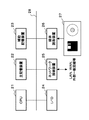
図6は、図1のCPU9、メモリ10、フレームメモリ11及び表示部12を、共焦点走査型顕微鏡に接続するパソコン等の汎用の情報処理装置を用いる構成とした場合の、上記汎用の情報処理装置のシステムの環境を示す図である。
この情報処理装置は、図6の様にCPU21、主記憶装置22、ハードディスク等による補助記憶装置23、ディスプレイ、キーボード等の入出力装置(I/O)24、モデム等のネットワーク接続装置25及びディスク、磁気テープなどの可搬記憶媒体から記憶内容を読み出す媒体読取り装置26を有し、これらが互いにバス28により接続される構成を備えている。
【0050】
CPU21は、補助記憶装置23に記憶されたプログラムに基づいて、補助記憶装置23内に事前に記録・設定されている、観察試料の種類、対物レンズの種類や倍率に依存する、AFの再実行条件や観察対象部の検索処理に用いる種々の条件等を参照して図4の処理を実現する。
【0051】
図6の情報処理システムでは、媒体読取り装置26により磁気テープ、フレキシブルディスク、CD−ROM、MO等の記憶媒体27に記憶されているプログラム、データを読み出し、これを主記憶装置22または補助記憶装置23にダウンロードする。そして本実施形態による各処理は、CPU21がこのプログラムやデータを実行することにより、ソフトウエア的に実現することも可能である。
【0052】
また、この情報処理システムでは、フレキシブルディスク等の記憶媒体27を用いてアプリケーションソフトの交換が行われる場合がある。よって、本発明は、共焦点走査型顕微鏡やその位置合わせ方法に限らず、コンピュータにより使用されたときに、上述の本発明の実施の形態の機能をコンピュータに行わせるためのコンピュータ読み取り可能な記憶媒体27として構成することもできる。
【0053】
この場合、「記憶媒体」には、例えば図7に示されるように、CD−ROM、フレキシブルディスク(あるいはMO、DVD、リムーバブルハードディスク等であってもよい)等の媒体駆動装置37に脱着可能な可搬記憶媒体36や、ネットワーク回線33経由で送信される外部の装置(サーバ等)内の記憶手段(データベース等)32、あるいは情報処理装置31の本体34内のメモリ(RAM又はROM、ハードディスク等)35等が含まれる。可搬記憶媒体36や記憶手段(データベース等)32に記憶されているプログラムは、本体34内のメモリ(RAM又はROM、ハードディスク等)35にロードされて、実行される。
【0054】
尚本実施形態では、AF制御時に対物レンズを移動していたが、試料を載せたステージを光軸方向に移動する構成としても良い。
またAFを実行する位置の移動を行う際、ステージを用いて試料を移動していたが、試料を移動させず二次元走査用スキャナ2による走査位置を制御することで、AFを実行する位置を移動しても良い。
【0055】
更に観察対象部の検索では、しきい値を用いて立下りエッジの位置を検索して行っていたが、この方式に限定されるものではなく、一般的に用いられる画像認識方式の中から試料の形状に合わせて適宜なものを選択して用いても良い。
またAFを実行する位置を観察画像の中央としていたが、この限りではなく、観察画像内のどの位置でも良い。
【0056】
更に、低倍率の対物レンズで観察対象部を検索して検索結果に基いて移動する時に、移動量は予め指定してあるものを用いているが、検索時に求めた平均輝度データ情報から、続いて行う高倍率対物レンズでのAFの実行において、AFが必ず成功する位置を検索してその位置へ移動するようにしても良い。
【0057】
またAFを実行する時に、AFが失敗した時に移動する方向のライン分のデータをメモリに保持しておき、AFに失敗した時には保持しておいた輝度データを用いて次にAFが必ず成功する位置を検索し、その位置へ移動してAFを実行する構成としても良い。
【0058】
更に対物レンズに低倍率の対物レンズと高倍率の対物レンズを用いて位置合わせを行っているが、試料の状態や観察部の精度等によっては、同じ倍率の対物レンズを用いて位置合わせを行っても良い。
また本実施形態では、実際に低倍率の対物レンズと、観察に用いる高倍率の対物レンズとで2度位置合わせを行っているが、観察に用いる対物レンズのみで1度だけ位置合わせを行っても良い。
【0059】
【発明の効果】
以上詳細に説明したように、本発明によれば、所望の画像を得るまでに手間がかからない共焦点走査型顕微鏡を実現することができる。
また、画像を用いた計測で再現性を向上した共焦点走査型顕微鏡実現することができる。
【図面の簡単な説明】
【図1】本実施形態における共焦点走査型顕微鏡のシステムの概略構成を示す図である。
【図2】本実施形態における観察試料を示す図である。
【図3】ここで観察対象部の検索についての説明図である。
【図4】本実施形態における共焦点走査型顕微鏡による試料観察時の動作処理を示すフローチャートである。
【図5】観察対象部の検索処理を示すフローチャートである。
【図6】情報処理装置のシステムの環境を示す図である。
【図7】記憶媒体の例を示す図である。
【図8】山登りサーボ方式の自動焦点検出方法の一例を説明するものである。
【符号の説明】
1 光源
2 二次元走査用スキャナ
3 対物レンズ
4 試料
5 ステージ
6 光検出器
7 A/D変換器
8 移動駆動部
9、21 CPU
10 メモリ
11 フレームメモリ
12 表示部
22 主記憶装置
23 補助記憶装置
24 入出力装置
25 ネットワーク接続装置
26 媒体読取り装置[0001]
BACKGROUND OF THE INVENTION
The present invention relates to a confocal scanning microscope, and more particularly to a confocal scanning microscope having an automatic focus detection function.
[0002]
[Prior art]
A confocal scanning microscope uses a point light source to scan a specific observation target area on the sample surface while irradiating it with a pinpoint, and converts only reflected light from the sample surface into the electrical signal. In addition, the light intensity information on the sample surface can be obtained from this detection signal. Furthermore, the three-dimensional information on the sample surface can be obtained by obtaining multiple pieces of information on the in-focus position in the depth direction. Is.
[0003]
The confocal scanning microscope combines a point light source such as a laser beam and a pinhole provided in front of the photodetector to illuminate the sample surface with a pinpoint and suppress scattered light from other than the measurement point with the pinhole. . In other words, in a confocal scanning microscope, noise light from the vicinity of the measurement point is imaged around the pinhole, and light from a surface shifted in the optical axis direction is spread in front of the pinhole by the objective lens and pinholed. Suppress. Thereby, the reflected light from other than the measurement point is cut, and only the reflected light at the height position in focus is converted by the photoelectric converter so that only one point in the three-dimensional space can be measured.
[0004]
By the way, various types of automatic focus detection methods applied in a microscope or the like have been proposed.
For example, brightness data obtained by detecting reflected light on the sample surface with a light receiving element is treated as a contrast amount, and the stage or objective lens is moved in the Z-axis direction and focused so that the contrast amount becomes the highest. Some perform autofocus (hereinafter abbreviated as AF) control by a servo system.
[0005]
FIG. 8 illustrates an example of such a hill-climbing servo type automatic focus detection method.
First, an objective lens (not shown) is moved in the Z-axis direction (optical axis direction) away from the sample (left direction in FIG. 8) at a first pitch (white circle in the figure) while reflecting the reflected light from the sample surface. Luminance data is obtained, and it is monitored that the luminance value exceeds the threshold value TH. When a luminance value exceeding the threshold value TH is detected, this time, in the second pitch finer than the first pitch (black triangle in the figure), the objective value increases in the direction of the luminance value in the Z-axis direction (left direction in the figure). The maximum luminance value H is monitored while moving the lens. Then, after the maximum luminance value H is detected, the objective lens is moved in the same direction with the second pitch, and a point M where the luminance value is 50% of the maximum luminance value H is found, and the objective lens is moved at that position. Is paused.
[0006]
Next, the moving direction of the objective lens is reversed (right direction in FIG. 8), and this time passes through the position where the maximum luminance value H is obtained at a third pitch (white triangle mark in the same figure) finer than the second pitch. To move. If it finds a point whose luminance value is smaller than the luminance value acquired immediately before three times in succession, it is judged that the focal point of the true highest luminance has passed, and the objective lens is moved to the highest luminance position F. Complete the focus.
[0007]
[Problems to be solved by the invention]
In the AF control of the confocal scanning microscope, the supplemental range of the in-focus position is affected by the magnification of the objective lens.
When a low-magnification objective lens of about 5 to 10 times is used, the supplementary range is wide because the focal depth is large, and when an objective lens of 50 times or more is used, the supplementary range is narrow because the focal depth is small. Therefore, when observing with a high-magnification objective lens, first, the in-focus position is roughly detected with the low-magnification objective lens, and then fine-adjusted with the high-magnification objective lens to obtain the in-focus position.
[0008]
In the detection of the in-focus position, it is easy to detect if the change in the brightness value is large within the range where the brightness value is not saturated. Therefore, when the luminance value of the observation target portion is low, the in-focus position is detected in the portion where the luminance of the sample (surface) is high, and after the in-focus position is detected, the observation target portion is moved to a desired position such as the center of the observation image. There are many cases of moving. When observing with a high-magnification objective lens, the operations of detecting the in-focus position and moving to the observation target portion are performed in each of the low-magnification objective lens and the high-magnification objective lens.
[0009]
In addition, when the AF control fails because there is dust or the like at the position used for detecting the in-focus position, it is necessary to manually change the detection position and then perform the AF control again. If the AF control fails, the AF control and the movement to the observation position are repeated before actually observing the sample. However, the movement to the desired position such as the observation position is caused by the magnification of the objective lens. The higher it is, the more difficult it will be, and it will be very time consuming.
[0010]
Furthermore, when reproducibility is required, such as measurement using an observation image, it is generally desirable to make the detection position of the in-focus position constant because it is desired to stably detect the in-focus position. However, since the optical axis of the objective lens has an error for each objective lens, the detection position may change when the objective lens is switched.
[0011]
In view of the above problems, an object of the present invention is to provide a confocal scanning microscope that can easily acquire an observation image focused on an observation target portion.
Another object of the present invention is to provide a confocal scanning microscope with improved reproducibility in measurement using an observation image.
[0012]
[Means for Solving the Problems]
A confocal scanning microscope, which is one aspect of the present invention, is a confocal scanning microscope having an autofocus function, in which a first focusing lens that detects an in-focus position by executing autofocus with a first objective lens. A first observation target part searching means for searching for a predetermined position of the observation sample in order to determine the first observation target part after the focus detection means and the first in-focus position detection by the first focus detection means. And a first moving means for moving a relative position between the observation sample and the first objective lens based on a search result by the first observation target part searching means, and the first observation target The part search means obtains an average value of luminance data obtained by scanning a plurality of lines from the predetermined position, and determines the first observation target part using the average value. Is.
[0017]
In addition, an alignment method in a confocal scanning microscope, which is another aspect of the present invention, is an alignment method in a confocal scanning microscope having an autofocus function, and is performed automatically by a first objective lens. The focus is detected to detect the in-focus position, and after detecting the in-focus position, a predetermined position of the observation sample is searched to determine the observation target portion, and the observation sample and the The relative position with respect to the first objective lens is moved. In the search, an average value of luminance data obtained by scanning a plurality of lines from the predetermined position is obtained, and the average value is used. The observation target part is determined.
[0018]
Note that the information processing apparatus reads the program from the information processing apparatus readable storage medium storing the program for causing the information processing apparatus to perform the same control as the function performed by each configuration of the present invention described above and executes it. By doing so, the above-described problems can be solved.
[0019]
DETAILED DESCRIPTION OF THE INVENTION
Hereinafter, embodiments of the present invention will be described with reference to the drawings.
FIG. 1 is a diagram illustrating a schematic configuration of a system of a confocal scanning microscope according to the present embodiment.
[0020]
In the system configuration of FIG. 1, a
[0021]
The
[0022]
The objective lens 3 can be continuously moved in the optical axis direction of the spot light, that is, in the Z-axis direction by a
[0023]
The stage 5 moves the sample 4 in a direction perpendicular to the optical axis of the spot light, that is, in the XY axis direction, based on a control instruction from the CPU 9.
The
[0024]
The CPU 9 issues a control instruction to each component shown in FIG. 1 to control the operation. The
[0025]
The CPU 9 implements the
[0026]
The
[0027]
The
Next, the processing operation at the time of observation in the present embodiment of the microscope apparatus having the above configuration will be described.
[0028]
In the following description, a case where a line-and-space shape in which a portion with high luminance and a portion with low luminance are continuous as shown in FIG. This sample is roughly known in advance, and the width of the portion with high luminance is about 30 μm, and the width of the portion with low luminance is about 5 μm. In this embodiment, the case of observing the line width of the portion where the luminance of the sample is low will be described as an example.
[0029]
When starting observation, first, in order to detect a rough focus position, a low-magnification objective lens is set in the microscope and AF control is executed. The center position of the observation image is used as the AF execution position, and AF is executed using the luminance value at this position. The present invention does not depend on the AF method. Therefore, since the AF method performed here may be performed by any commonly used method such as the above-described hill-climbing servo method, a detailed description of AF is omitted.
[0030]
When AF fails, if the AF re-execution condition is satisfied, the AF execution position is moved, and AF execution is repeated until AF succeeds or the re-execution condition is not satisfied. At this time, the AF re-execution condition and the movement amount of the AF execution position when it fails are calculated and set in advance from the shape of the sample. For example, assuming that the AF execution position is moved 10 μm to the left in the horizontal direction, and the re-execution condition is movable only within a high luminance range, the AF is executed a maximum of three times.
[0031]
If AF with a low-magnification objective lens is successful, the observation target portion is next searched.
Here, the search of the observation target portion will be described with reference to FIG.
FIG. 3 is a diagram for explaining the observation target part searching operation and the stage moving operation according to the present embodiment.
[0032]
First, the sample 4 is scanned at a position where AF is successfully performed with a low-magnification objective lens, and a scanned image is obtained. Then, luminance data for several lines near the horizontal center of the image is acquired from the scanned image. The number of lines to be acquired and the acquisition position are set in advance according to the sample shape. In FIG. 3, luminance data for several lines is acquired in the horizontal direction from the W portion in FIG.
[0033]
Next, the acquired luminance data is averaged by adding the luminance values at the same position in the vertical direction to create average luminance data for one line as shown in FIG. In the case of the figure, since the sample is a line-and-space shape, the luminance data for one line is a value in which the high luminance portion and the low luminance portion are sequentially repeated at the same interval. In the present embodiment, by using this average luminance data, it is possible to prevent a foreign matter such as dust from existing in the observation target portion or a search failure due to noise.
[0034]
In this embodiment, since the width of the low portion of the luminance data is observed, the position of the edge that is the boundary between the high luminance portion and the low luminance portion of the sample is searched from the created average luminance data as shown in FIG. .
The edge position here is the first time that the brightness becomes lower than the preset threshold value Ti when the average brightness data I in FIG. 3A is searched from the left side (in the direction of increasing X). The crossing position (E portion in the figure). This edge position is used as a search result of the observation target portion. If the search for the edge position fails, the observation position is changed and the AF is performed again.
[0035]
When the search of the observation target part is successful, the stage is moved so that a position (F position in FIG. 3C) that is a minute amount away from the searched edge position is the position where AF is performed. The edge position searched as the observation target part is a position where the luminance is lowered, and if AF is performed at that position, there is a high possibility of failure, so the position obtained by a predetermined method from the searched edge position For example, a position separated by a minute amount (−α μm) from the edge position is set as a position to execute AF. The length α away from the edge position is calculated and set in advance from the shape of the sample, the area size used for AF, and the like.
[0036]
When the movement of the stage is completed, the objective lens is switched to a high-magnification objective lens used for observation in order to detect a more detailed in-focus position. The position Z of the objective lens at this time does not change from the position where the AF is successful with the low-magnification objective lens. From this state, AF is executed using a high-magnification objective lens.
[0037]
When this AF fails, the position is moved until the AF succeeds or the re-execution condition is not satisfied, and the execution of AF is repeated, as in the case where the AF fails with a low magnification objective lens. Note that the movement amount and re-execution conditions at this time are set for the high-magnification objective lens, and the movement amount is usually smaller than the value for the low-magnification objective lens.
[0038]
When AF is successful, the observation target portion is next searched. This search method is basically the same as that for the low-magnification objective lens, but when the search fails, the stage is moved to the right by the horizontal size of the observation image displayed on the
[0039]
When the search of the observation target part is successful, the stage is moved so that the observation target part is at the center of the image. As a result, the observation target part is located at the center, and therefore, if the observation image is taken in as it is, a desired observation elephant can be obtained.
As described above, in the confocal scanning microscope according to the present embodiment, the detection position of the in-focus position is stable, and it does not take time to obtain a desired image.
[0040]
In addition, an image with a stable in-focus position is obtained, and the measurement target portion is always located near the center of the image with high measurement accuracy with a confocal scanning microscope, so that reproducibility is improved by measurement using an image.
FIG. 4 is a flowchart showing an operation process at the time of sample observation by the confocal scanning microscope in the present embodiment. The processing in FIG. 9 is realized by the CPU 9 controlling the confocal scanning microscope based on the program in the
[0041]
When starting the observation, in order to detect a rough focus position first in step S101, a low-magnification objective lens is set, and AF is executed in step S102.
If AF in step S102 fails (No in step S103), the AF execution position is moved as step S122 if the AF re-execution condition previously set and stored in the memory is satisfied (step S121, Yes). After that, the process returns to step S102 and AF is executed again. While the re-execution condition is satisfied, the processes in steps S102, S103, S121, and S122 are repeated until AF is successful in step S102.
[0042]
If the AF in step S102 is successful (step S103, Yes), then the observation target part search process is performed as step S104.
FIG. 5 is a flowchart showing the observation target part search processing performed in steps S104, S110, and S116.
[0043]
When this process is called, first, luminance data for several lines is acquired from a predetermined position near the center in the horizontal direction of the image from the scanned image (step S201).
Next, the luminance data acquired in step S201 is averaged by adding the luminance values at the same position in the vertical direction to generate average luminance data for one line (step S202). In step S203, the edge position is searched from the average luminance data created in step S202. Then, the search process is terminated and the process returns to FIG.
[0044]
As a result of the search in step S104, when the edge position cannot be obtained and the search of the observation target portion fails (step S105, No), the observation position is moved and changed as step S114, and then the process is performed. Returning to S102, AF with a low-magnification objective lens is executed again at another observation position.
[0045]
If the search of the observation target part in step S104 is successful (step S105, Yes), the position where the AF is performed based on the position determined in advance based on the position searched from the observation target part in step S104 And the stage is moved so that the position is at the center of the observation image (step S106).
[0046]
When the movement of the stage is completed, in order to detect a detailed in-focus position, the objective lens is switched to a high-magnification objective lens that is actually used for observation (step S107), and AF is executed (step S108).
When AF fails in step S108 (No in step S109), the AF re-execution condition for the high-magnification objective lens set and stored in the memory in advance is satisfied, as in the case of AF failure with the low-magnification objective lens. If so (step S119, Yes), after moving the position for the length set for the high-magnification objective lens as step S120 and changing the position where AF is executed, the process returns to step S108 and again Execute AF. While the re-execution condition is satisfied, steps S108, S109, S119, and S120 are repeated until AF is successful in step S108. If the re-execution condition is not satisfied (No at Step S119), the process is terminated.
[0047]
When AF in step S108 is successful (step S109, Yes), the observation target part is searched by the process shown in FIG. 5 as step S110.
When the search in step S110 fails (No in step S111), the stage is moved right by the horizontal size of the observation image (step S115), and the search process of the observation target portion in FIG. 5 is performed again (step S115). S116). If AF fails in the search process again in step S116 (No in step S117), the observation position is moved and changed as step S118, and then the process returns to step S101 to again reduce the magnification at another observation position. The processing is restarted from AF with the objective lens.
[0048]
When the search of the observation target part is successful in step S110 or step S116 (step S111 or S117, Yes), the stage is moved so that the observation target part is at the center of the observation image (step S112). When the sample is scanned in this state and an observation image is captured (step S113), a desired observation image is obtained.
[0049]
FIG. 6 shows the general-purpose information processing when the CPU 9, the
As shown in FIG. 6, the information processing apparatus includes a
[0050]
Based on the program stored in the
[0051]
In the information processing system of FIG. 6, a program and data stored in a
[0052]
In this information processing system, application software may be exchanged using a
[0053]
In this case, as shown in FIG. 7, for example, as shown in FIG. 7, the “storage medium” is detachable from a medium drive device 37 such as a CD-ROM, a flexible disk (or may be an MO, DVD, removable hard disk, etc.). Portable storage medium 36, storage means (database or the like) 32 in an external device (server or the like) transmitted via network line 33, or memory (RAM or ROM, hard disk or the like) in
[0054]
In this embodiment, the objective lens is moved during the AF control. However, the stage on which the sample is placed may be moved in the optical axis direction.
Further, when moving the position where AF is executed, the sample is moved using the stage, but the position where AF is executed is controlled by controlling the scanning position by the two-
[0055]
Furthermore, in the search of the observation target part, the position of the falling edge is searched using a threshold value. However, the present invention is not limited to this method, and a sample is selected from commonly used image recognition methods. An appropriate one may be selected and used according to the shape.
Moreover, although the position where AF is executed is the center of the observation image, this is not restrictive, and any position in the observation image may be used.
[0056]
Furthermore, when searching for the observation target portion with a low-magnification objective lens and moving based on the search result, the amount of movement specified in advance is used, but from the average luminance data information obtained during the search, In the execution of AF with the high-magnification objective lens performed in this way, a position where the AF always succeeds may be searched and moved to that position.
[0057]
Further, when executing AF, data for the line in the moving direction is stored in the memory when AF fails, and when the AF fails, AF is surely succeeded by using the stored luminance data. The position may be searched and moved to that position to execute AF.
[0058]
In addition, the objective lens is aligned using a low-magnification objective lens and a high-magnification objective lens. However, depending on the condition of the sample and the accuracy of the observation part, alignment is performed using an objective lens with the same magnification. May be.
Further, in the present embodiment, the alignment is performed twice with the low-magnification objective lens and the high-magnification objective lens actually used for observation, but the alignment is performed only once with only the objective lens used for observation. Also good.
[0059]
【The invention's effect】
As described in detail above, according to the present invention, it is possible to realize a confocal scanning microscope that does not require time and effort until a desired image is obtained.
In addition, it is possible to realize a confocal scanning microscope having improved reproducibility by measurement using an image.
[Brief description of the drawings]
FIG. 1 is a diagram illustrating a schematic configuration of a system of a confocal scanning microscope according to the present embodiment.
FIG. 2 is a diagram showing an observation sample in the present embodiment.
FIG. 3 is an explanatory diagram for searching for an observation target portion.
FIG. 4 is a flowchart showing an operation process at the time of sample observation by a confocal scanning microscope according to the present embodiment.
FIG. 5 is a flowchart showing a search process for an observation target portion.
FIG. 6 is a diagram illustrating a system environment of an information processing apparatus.
FIG. 7 is a diagram illustrating an example of a storage medium.
FIG. 8 illustrates an example of a hill-climbing servo type automatic focus detection method.
[Explanation of symbols]
1 Light source
2 Two-dimensional scanning scanner
3 Objective lens
4 samples
5 stages
6 Light detector
7 A / D converter
8 Movement drive unit
9, 21 CPU
10 memory
11 frame memory
12 Display section
22 Main memory
23 Auxiliary storage
24 I / O devices
25 Network connection device
26 Media reader
Claims (9)
第1の対物レンズによってオートフォーカスを実行して合焦点位置を検出する第1の合焦点検出手段と、
前記第1の合焦点検出手段による合焦点位置の検出後、第1の観察対象部を決定するため観察試料の予め定められた位置を検索する第1の観察対象部検索手段と、
前記第1の観察対象部検索手段による検索結果に基いて前記観察試料と前記第1の対物レンズとの相対位置を移動する第1の移動手段と、
を備え、
前記第1の観察対象部検索手段は、前記予め定められた位置から複数ライン分走査して得られた輝度データの平均値を求め、該平均値を用いて前記第1の観察対象部を決定することを特徴とする共焦点走査型顕微鏡。In a confocal scanning microscope with an autofocus function,
First in-focus detection means for detecting an in-focus position by executing auto-focusing with the first objective lens;
A first observation target part searching means for searching for a predetermined position of the observation sample in order to determine the first observation target part after detecting the in-focus position by the first focus detection means;
First moving means for moving a relative position between the observation sample and the first objective lens based on a search result by the first observation target part searching means;
Equipped with a,
The first observation target part searching means obtains an average value of luminance data obtained by scanning a plurality of lines from the predetermined position, and determines the first observation target part using the average value. A confocal scanning microscope characterized by:
前記第2の合焦点検出手段による合焦点位置の検出後、第2の観察対象部を決定するため前記観察試料の予め定められた位置を検索する第2の観察対象部検索手段と、
前記第2の観察対象部検索手段による検索結果に基いて前記観察試料と前記第2の対物レンズとの相対位置を移動する第2の移動手段と、
を更に備えたことを特徴とする請求項1に記載の共焦点走査型顕微鏡。A second in-focus detection means for detecting an in-focus position by performing auto-focusing by the second objective lens after movement by the first moving means;
A second observation target part searching means for searching for a predetermined position of the observation sample in order to determine a second observation target part after detection of the in-focus position by the second focus detection means;
Second moving means for moving a relative position between the observation sample and the second objective lens based on a search result by the second observation target part searching means;
The confocal scanning microscope according to claim 1, further comprising:
第1の対物レンズによってオートフォーカスを実行して合焦点位置を検出し、前記合焦点位置の検出後、観察対象部を決定するため観察試料の予め定められた位置を検索し、
前記検索結果に基いて前記観察試料と前記第1の対物レンズとの相対位置を移動させるものであり、
前記検索では、前記予め定められた位置から複数ライン分走査して得られた輝度データの平均値を求め、該平均値を用いて前記観察対象部を決定することを特徴とする共焦点走査型顕微鏡における位置合わせ方法。An alignment method in a confocal scanning microscope having an autofocus function,
Autofocus is performed by the first objective lens to detect the in-focus position, and after the in-focus position is detected, a predetermined position of the observation sample is searched for determining the observation target part ,
Based on the search result, the relative position of the observation sample and the first objective lens is moved ,
In the search, an average value of luminance data obtained by scanning a plurality of lines from the predetermined position is obtained, and the observation target portion is determined using the average value. Positioning method in a microscope.
第1の対物レンズによってオートフォーカスを実行させて合焦点位置を検出し、前記合焦点位置検出後、観察対象部を決定するため観察試料の予め定められた位置を検索し、
前記検索結果に基いて前記観察試料と前記第1の対物レンズとの相対位置を移動させることを前記情報処理装置に行わせるプログラムであって、
前記検索では、前記予め定められた位置から複数ライン分走査して得られた輝度データの平均値を求め、該平均値を用いて前記観察対象部を決定することを特徴とするプログラム。When used by the confocal scanning microscope and an information processing apparatus connected with an autofocus function,
Autofocus is performed by the first objective lens to detect the in-focus position, and after the in-focus position is detected, a predetermined position of the observation sample is searched to determine the observation target part ,
A program for causing the information processing apparatus to move a relative position between the observation sample and the first objective lens based on the search result ,
In the search, an average value of luminance data obtained by scanning a plurality of lines from the predetermined position is obtained, and the observation target part is determined using the average value .
第1の対物レンズによってオートフォーカスを実行させて合焦点位置を検出し、前記合焦点位置検出後、観察対象部を決定するため観察試料の予め定められた位置を検索し、
前記検索結果に基いて前記観察試料と前記第1の対物レンズとの相対位置を移動させることを前記情報処理装置に行わせるためのプログラムを記憶した前記情報処理装置が読み取り可能な記憶媒体であって、
前記検索では、前記予め定められた位置から複数ライン分走査して得られた輝度データの平均値を求め、該平均値を用いて前記観察対象部を決定することを特徴とする記憶媒体。When used by an information processing device connected to a confocal scanning microscope with an autofocus function,
Autofocus is performed by the first objective lens to detect the in-focus position, and after the in-focus position is detected, a predetermined position of the observation sample is searched to determine the observation target part ,
It met the information processing apparatus readable storage medium storing a program for causing moving the relative position of the said observation sample on the basis of the search results first objective lens to the information processing apparatus And
In the search, an average value of luminance data obtained by scanning a plurality of lines from the predetermined position is obtained, and the observation target part is determined using the average value .
Priority Applications (1)
| Application Number | Priority Date | Filing Date | Title |
|---|---|---|---|
| JP2001241317A JP4878708B2 (en) | 2001-08-08 | 2001-08-08 | Confocal scanning microscope, alignment method thereof, program, and storage medium |
Applications Claiming Priority (1)
| Application Number | Priority Date | Filing Date | Title |
|---|---|---|---|
| JP2001241317A JP4878708B2 (en) | 2001-08-08 | 2001-08-08 | Confocal scanning microscope, alignment method thereof, program, and storage medium |
Publications (3)
| Publication Number | Publication Date |
|---|---|
| JP2003057552A JP2003057552A (en) | 2003-02-26 |
| JP2003057552A5 JP2003057552A5 (en) | 2008-08-14 |
| JP4878708B2 true JP4878708B2 (en) | 2012-02-15 |
Family
ID=19071786
Family Applications (1)
| Application Number | Title | Priority Date | Filing Date |
|---|---|---|---|
| JP2001241317A Expired - Fee Related JP4878708B2 (en) | 2001-08-08 | 2001-08-08 | Confocal scanning microscope, alignment method thereof, program, and storage medium |
Country Status (1)
| Country | Link |
|---|---|
| JP (1) | JP4878708B2 (en) |
Families Citing this family (4)
| Publication number | Priority date | Publication date | Assignee | Title |
|---|---|---|---|---|
| DE502004002547D1 (en) * | 2004-06-22 | 2007-02-15 | Polytec Gmbh | Device for optically measuring an object |
| JP4599941B2 (en) * | 2004-08-20 | 2010-12-15 | 株式会社ニコン | Automatic focus detection apparatus and microscope system including the same |
| JP6173154B2 (en) * | 2013-10-01 | 2017-08-02 | オリンパス株式会社 | Microscope system |
| DE102018107356A1 (en) | 2018-03-28 | 2019-10-02 | Carl Zeiss Microscopy Gmbh | Autofocus with angle-variable illumination |
Family Cites Families (4)
| Publication number | Priority date | Publication date | Assignee | Title |
|---|---|---|---|---|
| JP3683298B2 (en) * | 1995-02-02 | 2005-08-17 | オリンパス株式会社 | Defect detection microscope |
| US5671288A (en) * | 1995-05-31 | 1997-09-23 | Neopath, Inc. | Method and apparatus for assessing slide and specimen preparation quality |
| JP4574758B2 (en) * | 1998-03-19 | 2010-11-04 | オリンパス株式会社 | Microscope image observation device |
| JP2001091840A (en) * | 1999-09-20 | 2001-04-06 | Olympus Optical Co Ltd | Microscope system |
-
2001
- 2001-08-08 JP JP2001241317A patent/JP4878708B2/en not_active Expired - Fee Related
Also Published As
| Publication number | Publication date |
|---|---|
| JP2003057552A (en) | 2003-02-26 |
Similar Documents
| Publication | Publication Date | Title |
|---|---|---|
| JP5043629B2 (en) | Laser scanning microscope and measuring method of surface shape thereof | |
| JP5941395B2 (en) | Image acquisition device and focus method of image acquisition device | |
| JPWO2005114293A1 (en) | Microscope equipment | |
| JPWO2005114287A1 (en) | Microscope equipment | |
| JP6662529B2 (en) | System and method for continuous asynchronous autofocus of optics | |
| JP2017188731A (en) | Imaging system and imaging method | |
| JP5053691B2 (en) | Specimen scanner device and specimen position detection method using the device | |
| JPH05137047A (en) | Method and device for detection of focal point | |
| JPH09281384A (en) | Autofocusing controller | |
| JP4878708B2 (en) | Confocal scanning microscope, alignment method thereof, program, and storage medium | |
| JP3579166B2 (en) | Scanning laser microscope | |
| JP4179790B2 (en) | Confocal scanning optical microscope | |
| JP2008046484A (en) | Automatic focus detecting device and method | |
| JP2013088570A (en) | Microscope apparatus | |
| JP4398183B2 (en) | Confocal microscope | |
| JP6631650B2 (en) | Scanning probe microscope | |
| JP2001059935A (en) | Automatic focus detector, automatic focus detecting method and automatic focus detecting program-recorded recording medium | |
| JP4791155B2 (en) | Focusing method, focusing device, and measuring apparatus using the same | |
| JP4503804B2 (en) | Three-dimensional information acquisition method and confocal scanning microscope | |
| JP2008261829A (en) | Surface measuring device | |
| JP4128256B2 (en) | Scanning laser microscope | |
| JP2001059936A (en) | Automatic focus detector, automatic focus detecting method and automatic focus detecting program-recorded recording medium | |
| JP6856145B2 (en) | Scanning probe microscope and analysis method | |
| JP2006030304A (en) | Focus detector for microscope | |
| JP4679840B2 (en) | Laser scanning microscope |
Legal Events
| Date | Code | Title | Description |
|---|---|---|---|
| A521 | Written amendment |
Free format text: JAPANESE INTERMEDIATE CODE: A523 Effective date: 20080630 |
|
| A621 | Written request for application examination |
Free format text: JAPANESE INTERMEDIATE CODE: A621 Effective date: 20080630 |
|
| A977 | Report on retrieval |
Free format text: JAPANESE INTERMEDIATE CODE: A971007 Effective date: 20110826 |
|
| A131 | Notification of reasons for refusal |
Free format text: JAPANESE INTERMEDIATE CODE: A131 Effective date: 20110913 |
|
| A521 | Written amendment |
Free format text: JAPANESE INTERMEDIATE CODE: A523 Effective date: 20111025 |
|
| TRDD | Decision of grant or rejection written | ||
| A01 | Written decision to grant a patent or to grant a registration (utility model) |
Free format text: JAPANESE INTERMEDIATE CODE: A01 Effective date: 20111122 |
|
| A01 | Written decision to grant a patent or to grant a registration (utility model) |
Free format text: JAPANESE INTERMEDIATE CODE: A01 |
|
| A61 | First payment of annual fees (during grant procedure) |
Free format text: JAPANESE INTERMEDIATE CODE: A61 Effective date: 20111129 |
|
| R151 | Written notification of patent or utility model registration |
Ref document number: 4878708 Country of ref document: JP Free format text: JAPANESE INTERMEDIATE CODE: R151 |
|
| FPAY | Renewal fee payment (event date is renewal date of database) |
Free format text: PAYMENT UNTIL: 20141209 Year of fee payment: 3 |
|
| S531 | Written request for registration of change of domicile |
Free format text: JAPANESE INTERMEDIATE CODE: R313531 |
|
| R350 | Written notification of registration of transfer |
Free format text: JAPANESE INTERMEDIATE CODE: R350 |
|
| LAPS | Cancellation because of no payment of annual fees |