EP1625922B1 - Trägerelement - Google Patents
Trägerelement Download PDFInfo
- Publication number
- EP1625922B1 EP1625922B1 EP05076790A EP05076790A EP1625922B1 EP 1625922 B1 EP1625922 B1 EP 1625922B1 EP 05076790 A EP05076790 A EP 05076790A EP 05076790 A EP05076790 A EP 05076790A EP 1625922 B1 EP1625922 B1 EP 1625922B1
- Authority
- EP
- European Patent Office
- Prior art keywords
- plate
- section
- spacer
- supporting element
- stiffening section
- Prior art date
- Legal status (The legal status is an assumption and is not a legal conclusion. Google has not performed a legal analysis and makes no representation as to the accuracy of the status listed.)
- Expired - Lifetime
Links
Images
Classifications
-
- B—PERFORMING OPERATIONS; TRANSPORTING
- B28—WORKING CEMENT, CLAY, OR STONE
- B28B—SHAPING CLAY OR OTHER CERAMIC COMPOSITIONS; SHAPING SLAG; SHAPING MIXTURES CONTAINING CEMENTITIOUS MATERIAL, e.g. PLASTER
- B28B7/00—Moulds; Cores; Mandrels
- B28B7/0029—Moulds or moulding surfaces not covered by B28B7/0058 - B28B7/36 and B28B7/40 - B28B7/465, e.g. moulds assembled from several parts
- B28B7/0055—Mould pallets; Mould panels
-
- B—PERFORMING OPERATIONS; TRANSPORTING
- B28—WORKING CEMENT, CLAY, OR STONE
- B28B—SHAPING CLAY OR OTHER CERAMIC COMPOSITIONS; SHAPING SLAG; SHAPING MIXTURES CONTAINING CEMENTITIOUS MATERIAL, e.g. PLASTER
- B28B11/00—Apparatus or processes for treating or working the shaped or preshaped articles
- B28B11/24—Apparatus or processes for treating or working the shaped or preshaped articles for curing, setting or hardening
- B28B11/248—Supports for drying
-
- B—PERFORMING OPERATIONS; TRANSPORTING
- B28—WORKING CEMENT, CLAY, OR STONE
- B28B—SHAPING CLAY OR OTHER CERAMIC COMPOSITIONS; SHAPING SLAG; SHAPING MIXTURES CONTAINING CEMENTITIOUS MATERIAL, e.g. PLASTER
- B28B1/00—Producing shaped prefabricated articles from the material
- B28B1/08—Producing shaped prefabricated articles from the material by vibrating or jolting
- B28B1/081—Vibration-absorbing means
-
- B—PERFORMING OPERATIONS; TRANSPORTING
- B28—WORKING CEMENT, CLAY, OR STONE
- B28B—SHAPING CLAY OR OTHER CERAMIC COMPOSITIONS; SHAPING SLAG; SHAPING MIXTURES CONTAINING CEMENTITIOUS MATERIAL, e.g. PLASTER
- B28B11/00—Apparatus or processes for treating or working the shaped or preshaped articles
- B28B11/24—Apparatus or processes for treating or working the shaped or preshaped articles for curing, setting or hardening
Definitions
- the present invention relates to a supporting element for bricks that are dried while being supported thereon, comprising a plate with downwardly extending plate edges, between which plate edges a stiffening section extends, which stiffening section is connected to the plate at spaced-apart points of attachment on the bottom side of the plate.
- Such a plate is generally known, it is used in the brick industry for placing green bricks of clay or loam thereon.
- the stiffening section is spot-welded to the plate.
- the plate supporting the green bricks is subsequently taken to a drying space for drying the clay or loam.
- the plates with the green bricks of clay or loam are taken to a kiln, where they are baked into bricks.
- a major problem that occurs with the supporting elements that are currently being used is that the plate and the stiffening section vibrate against one another during handling and transport, which causes noise nuisance. Especially when large numbers of plates are being handled and transported, as is the case in the brick industry, this leads to objectionable noise. In the course of time several attempts have been made to solve this problem.
- a supporting element for drying bricks which provides a solution for the above problem, at least partially so, and which reduces the amount of noise nuisance to a considerable degree.
- this object is accomplished by a supporting element as referred to in the introduction, wherein a spacer is provided between two points of attachment so as to keep the stiffening section spaced from the plate between said two points of attachment. Since spacers push the plate and the stiffening section away from each other between the two points of attachment, contact between the plate and the stiffening section is not entirely prevented but considerably reduced. After all, the spacer has a damping effect on the vibration of both the plate and the stiffening section, as a result of which both the duration and the amplitude of the vibrations that occur during handling and transport are significantly reduced.
- the Belgium patent BE 558649 discloses a support element according to the preamble of claim 1 and a method of manufacturing such a support element according to the preamble of claim 8.
- German patent application DE 35 38 096 A1 discloses a supporting plate for drying stones which plate is provided with legs which keep the supporting plate at a distance from the underground at which the device is positioned.
- the supporting plate is provided with ribs at the bottom side of the supporting plate to make the supporting plate more rigid.
- the spacer functions as a means of attachment, and the location at which the spacer is present between the plate and the stiffening section can be regarded as a point of attachment.
- This special embodiment provides a supporting element for bricks being dried while being supported thereon, comprising a plate with downwardly extending plate edges, between which plate edges a stiffening section extends, which stiffening section is connected to the plate at spaced-apart points of attachment on the bottom side of the plate, wherein a spacer is provided as a means of attachment at at least one point of attachment for attaching the stiffening section to the plate and keeping it spaced therefrom.
- a suitable variant to this special embodiment is an embodiment in which the point of attachment extends a certain length, for example at least substantially the entire length of the stiffening section.
- the invention relates to a supporting element for bricks being dried while being supported thereon, comprising a plate with downwardly extending plate edges, between which plate edges a stiffening section extends along a certain length, which stiffening section is connected to the plate at spaced-apart points of attachment on the bottom side of the plate, which means of attachment comprise at least one spacer for keeping the stiffening section spaced from the plate at least substantially along the length thereof.
- the stiffening section is preferably an elongated section having a U-shaped cross-section, the ends of the legs of the stiffening section being flanged to form section edges used for connecting the stiffening section to the plate.
- the U-shape imparts a sufficient degree of rigidity to the supporting element to prevent the plate from deflecting under the load of the bricks.
- the bricks are comparatively heavy on account of the water that is present in the clay or the loam.
- the section edges extend parallel to the plate and thus provide a projecting surface for interconnecting the plate and the stiffening sections. If the ends of the legs furthermore extend away from each other, it will be easier to handle the section when connecting it to the plate.
- a spacer is provided between respective pairs of adjacent points of attachment of a section edge. It will be understood that in this way the damping effect of the spacer will be greatest.
- the spacer is preferably made of a resilient material. Although hard materials effectively reduce noise pollution as well, in that they push the plate and the stiffening section apart, a resilient material will provide an even better damping effect.
- the spacer is preferably resistant against repeated temperature fluctuations in the range from about 0 °C to about 120 °C. This ensures that the properties of the material will be retained after a number of drying and baking cycles of bricks on the plate.
- a spacer comprises elements made of plastic material.
- plastics that have been good vibration damping properties, and the elements can be fitted between the plate and the stiffening section in a simple manner. Once the plate and the stiffening section are interconnected, the force that is exerted on the elements by the plate and the stiffening section may already suffice for holding the plastic elements in their clamped-down position. It is also possible to bond the plastic elements to the plate and/or the stiffening section or attach them in another manner.
- the spacer comprises a filler material, for example a suitable putty or a suitable foam material such as PUR.
- a suitable filler material is easy to provide on the plate or the stiffening section and, after possible curing, will have a damping effect on the vibration of the stiffening section relative to the plate.
- the spacer comprises a tape. Tape, too, is easy to provide and can be affixed to the plate or in the stiffening section relatively long before the plate and the stiffening section are interconnected, without any of the desired properties noticeably deteriorating.
- the present invention further relates to a method for manufacturing a supporting element, comprising the steps of forming the plate and connecting the stiffening section to the bottom side of the plate, wherein a spacer is provided on the plate and/or the section edges, between two spot welds to be formed, prior to said connecting step.
- Providing the spacer in advance is easy because both the plate and the section edges are readily accessible. Especially in those cases where the spacer is provided on the section edges, a correct positioning will moreover be easy to realise. Only the positions of the points of attachment to be subsequently formed need to be taken into account in that case.
- a local difference in level is provided in the plate and/or the stiffening section for positioning the spacer.
- the local difference in level provides a marker point that helps to position the spacer correctly.
- local differences in level help to prevent spacers from being displaced during the period between the provision of the spacers and the connection of the stiffening section to the plate.
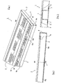
- the supporting plate 1 consists of a perforated plate 2, which is provided with upright edges 3 at the long sides and the short sides, which edges enable a good circulation of air via the bottom side of the plate during the drying process of bricks (not shown) that are present on the supporting plate.
- a U-shaped section 4 extends along the length of the brick drying plate 1, the ends of the legs of said U-shape being bent outwards at right angles so as to form edges 5. The section 4 prevents the plate 2 from deflecting when bearing the weight of the stones before or after drying.
- the section 4 is connected to the plate 2 by means of spot welds 6.
- Figure 2 is a longitudinal sectional view of a part of the brick drying plate 1 of figure 1 along the line II-II, in which a spacer, in this case in the form of a plate 7 of plastic material is shown to be present between the plate 2 and the edge 5 of the section, between two adjacent spot welds 6a and 6b.
- a spacer in this case in the form of a plate 7 of plastic material is shown to be present between the plate 2 and the edge 5 of the section, between two adjacent spot welds 6a and 6b.
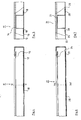
- Figure 3 is a cross-sectional view of a part of the brick drying plate 1 of figure 1 , along the line III-III in said figure. This figure clearly shows that the section 4 has two edges 5, and that a plate 7 of plastic material is provided between the section 4 and the plate 2 at every edge 5.
- Figures 4 and 5 are a longitudinal sectional view and a cross-sectional view (along the line V-V), respectively, of a supporting plate 11 comprising a plate 12 and a section 14 that is attached to the plate 12 at points of attachment by means of putty 18.
- the putty 18 consists of an elastic material and as such also functions as a spacer.
- Figures 6 and 7 are a longitudinal sectional view and a cross-sectional view (along the line VII-VII), respectively, of a supporting plate 21 comprising a plate 22 and a section 24 that is attached to the plate 22 at points of attachment by means of putty 28.
- the putty 28 consists of an elastic material and as such also functions as a spacer.
Landscapes
- Engineering & Computer Science (AREA)
- Chemical & Material Sciences (AREA)
- Ceramic Engineering (AREA)
- Mechanical Engineering (AREA)
- Structural Engineering (AREA)
- Manufacturing & Machinery (AREA)
- Devices For Post-Treatments, Processing, Supply, Discharge, And Other Processes (AREA)
- Finishing Walls (AREA)
- Manipulator (AREA)
- Saccharide Compounds (AREA)
- Piezo-Electric Or Mechanical Vibrators, Or Delay Or Filter Circuits (AREA)
- Processing Of Solid Wastes (AREA)
- Container, Conveyance, Adherence, Positioning, Of Wafer (AREA)
Claims (9)
- Trägerelement (1) für Ziegel, die getrocknet werden während sie darauf getragen werden, das eine Platte (2) mit sich nach unten erstreckenden Plattenrändern (3) aufweist, wobei sich zwischen den Plattenrändern ein Aussteifungsabschnitt (4) erstreckt, wobei der Aussteifungsabschnitt an beabstandeten Befestigungspunkten (6, 6a, 6b) an der Bodenseite der Platte mit der Platte verbunden ist,
dadurch gekennzeichnet, dass
ein Abstandhalter (7, 18, 28) zwischen zwei Befestigungspunkten vorgesehen ist, um so den Aussteifungsabschnitt zwischen den zwei Befestigungspunkten von der Platte beabstandet zu halten. - Trägerelement nach Anspruch 1, dadurch gekennzeichnet, dass der Aussteifungsabschnitt (4) ein länglicher Abschnitt mit einem U-förmigen Querschnitt ist, wobei die Enden der Schenkel des Aussteifungsabschnitts abgeflanscht sind, um Abschnittsränder (5) auszubilden, die zum Verbinden des Aussteifungsabschnitts mit der Platte (2) verwendet werden.
- Trägerelement nach Anspruch 2, dadurch gekennzeichnet, dass ein Abstandhalter (7) zwischen entsprechenden Paaren von benachbarten Verbindungspunkten (6a, 6b) eines Abschnittsrands (5) vorgesehen ist.
- Trägerelement nach einem oder mehreren der vorangehenden Ansprüche, dadurch gekennzeichnet, dass der Abstandhalter (7, 18, 28) aus einem nachgiebigen Material hergestellt ist.
- Trägerelement nach einem oder mehreren der vorangehenden Ansprüche, dadurch gekennzeichnet, dass der Abstandhalter (7) ein Element aus Kunststoffmaterial aufweist.
- Trägerelement nach einem oder mehreren der Ansprüche 1 bis 4, dadurch gekennzeichnet, dass der Abstandhalter (18, 28) Spachtelmasse oder einen Schaum als ein Füllmaterial aufweist.
- Trägerelement nach einem oder mehreren der Ansprüche 1 bis 4, dadurch gekennzeichnet, dass der Abstandhalter ein Band aufweist.
- Verfahren zur Herstellung eines Trägerelements (1) nach einem der vorangehenden Ansprüche, das die folgenden Schritte aufweist:Ausbilden der Platte (2), undVerbinden des Aussteifungsabschnitts (4) mit der Bodenseite der Platte,dadurch gekennzeichnet, dass
vor dem Verbindungsschritt ein Abstandhalter (7, 18, 28) an der Platte (2) und/oder den Abschnittsrändern (5) zwischen zwei auszubildenden Punktschweißungen (6, 6a, 6b) vorgesehen wird. - Verfahren nach Anspruch 8, dadurch gekennzeichnet, dass ein lokaler Niveauunterschied in der Platte und/oder dem Aussteifungsabschnitt zum Positionieren des Abstandhalters vorgesehen wird.
Applications Claiming Priority (1)
| Application Number | Priority Date | Filing Date | Title |
|---|---|---|---|
| NL1026812A NL1026812C2 (nl) | 2004-08-10 | 2004-08-10 | Ondersteuningsorgaan. |
Publications (2)
| Publication Number | Publication Date |
|---|---|
| EP1625922A1 EP1625922A1 (de) | 2006-02-15 |
| EP1625922B1 true EP1625922B1 (de) | 2008-10-15 |
Family
ID=34974243
Family Applications (1)
| Application Number | Title | Priority Date | Filing Date |
|---|---|---|---|
| EP05076790A Expired - Lifetime EP1625922B1 (de) | 2004-08-10 | 2005-08-02 | Trägerelement |
Country Status (5)
| Country | Link |
|---|---|
| EP (1) | EP1625922B1 (de) |
| AT (1) | ATE411146T1 (de) |
| DE (1) | DE602005010340D1 (de) |
| DK (1) | DK1625922T3 (de) |
| NL (1) | NL1026812C2 (de) |
Cited By (3)
| Publication number | Priority date | Publication date | Assignee | Title |
|---|---|---|---|---|
| EP4632305A1 (de) * | 2024-04-08 | 2025-10-15 | Stafier International B.V. | Stützelement mit verbesserter belüftung |
| NL2037414B1 (nl) * | 2024-04-08 | 2025-10-31 | Stafier Int B V | Ondersteuningsorgaan met aangepast versterkingsprofiel |
| NL2037415B1 (nl) * | 2024-04-08 | 2025-10-31 | Stafier Int B V | Ondersteuningsorgaan met verbeterde beluchting |
Families Citing this family (1)
| Publication number | Priority date | Publication date | Assignee | Title |
|---|---|---|---|---|
| DE102024109806A1 (de) * | 2024-04-09 | 2025-10-09 | Robert Thomas Metall- Und Elektrowerke Gmbh & Co. Kg | Trocknungsvorrichtung mit Palette |
Family Cites Families (4)
| Publication number | Priority date | Publication date | Assignee | Title |
|---|---|---|---|---|
| BE558649A (fr) * | 1957-06-24 | 1957-07-15 | Gevers & Cie | Claie pour le sechage de briques |
| DE3538096A1 (de) * | 1984-10-30 | 1986-05-28 | Robert Thomas Metall- und Elektrowerke, 5908 Neunkirchen | Vorrichtung zum abbinden aus beton gebildeter formsteine |
| FR2725588A1 (fr) * | 1994-10-14 | 1996-04-19 | Ppi Sa Pieces Frofiles Ind | Claie metallique pour le sechage des fruits |
| DE29705369U1 (de) * | 1997-03-25 | 1997-06-05 | Robert Thomas Metall- und Elektrowerke, 57290 Neunkirchen | Trockengutträger für keramische Formlinge |
-
2004
- 2004-08-10 NL NL1026812A patent/NL1026812C2/nl not_active IP Right Cessation
-
2005
- 2005-08-02 EP EP05076790A patent/EP1625922B1/de not_active Expired - Lifetime
- 2005-08-02 AT AT05076790T patent/ATE411146T1/de not_active IP Right Cessation
- 2005-08-02 DE DE602005010340T patent/DE602005010340D1/de not_active Expired - Lifetime
- 2005-08-02 DK DK05076790T patent/DK1625922T3/da active
Cited By (3)
| Publication number | Priority date | Publication date | Assignee | Title |
|---|---|---|---|---|
| EP4632305A1 (de) * | 2024-04-08 | 2025-10-15 | Stafier International B.V. | Stützelement mit verbesserter belüftung |
| NL2037414B1 (nl) * | 2024-04-08 | 2025-10-31 | Stafier Int B V | Ondersteuningsorgaan met aangepast versterkingsprofiel |
| NL2037415B1 (nl) * | 2024-04-08 | 2025-10-31 | Stafier Int B V | Ondersteuningsorgaan met verbeterde beluchting |
Also Published As
| Publication number | Publication date |
|---|---|
| DE602005010340D1 (de) | 2008-11-27 |
| EP1625922A1 (de) | 2006-02-15 |
| DK1625922T3 (da) | 2009-01-26 |
| NL1026812C2 (nl) | 2006-02-13 |
| ATE411146T1 (de) | 2008-10-15 |
Similar Documents
| Publication | Publication Date | Title |
|---|---|---|
| AU2013227435B2 (en) | Anti-spalling edging | |
| EP3208207B1 (de) | Palette mit stützelementen, die als einteilige skids konfiguriert sind, und zugehöriges verfahren | |
| CA2481278A1 (en) | Tilt-up concrete wall panel form and method of fabricating same | |
| EP2977161B1 (de) | Plattenstruktur zum herstellen von betonwaren | |
| EP1625922B1 (de) | Trägerelement | |
| KR102007464B1 (ko) | 조립형 보 거푸집 | |
| US2049925A (en) | Metal frame for constructing building boards | |
| CA2265024A1 (en) | Vibration damper | |
| EP0060352B1 (de) | Baukonstruktion | |
| DK2881518T3 (en) | Device for forming arc sections of straight circular cylinder | |
| GB2485181A (en) | An insulation panel support member | |
| CA1060180A (en) | Hollow panel structure and method for the construction thereof | |
| SE461161B (sv) | Golvvaermeplatta | |
| EP0202863A2 (de) | Stützrahmen für Siebplatten | |
| EP2050872A1 (de) | Schockbeständiges und/oder rutschfestes Element, insbesondere für Strukturen von tragenden Teillen oder Bedeckung von Gehbereichen, und dessen hesrstellungsverfahren | |
| JP2017008692A (ja) | 構造物修復工法 | |
| CN216130583U (zh) | 一种建筑施工用钢筋定位结构 | |
| KR102368434B1 (ko) | 금속 캐리어 타입의 발포패드 | |
| CN216710313U (zh) | 一种防板材变形的支架及板材运输机和热净化舱 | |
| GB2034386A (en) | Lintels | |
| JP4867260B2 (ja) | エレベータのかご床 | |
| JP2011189942A (ja) | サイロ用胴縁及びこれを用いたサイロの断熱構造 | |
| KR20180121819A (ko) | 횡단 레벨차 슬래브용 코너레벨강절재 및 이를 이용한 봉함재 설치공법 | |
| JPS58185845A (ja) | モルタル壁パネルとその製造方法 | |
| KR101950033B1 (ko) | 콘크리트 구조물용 방수시트 |
Legal Events
| Date | Code | Title | Description |
|---|---|---|---|
| PUAI | Public reference made under article 153(3) epc to a published international application that has entered the european phase |
Free format text: ORIGINAL CODE: 0009012 |
|
| AK | Designated contracting states |
Kind code of ref document: A1 Designated state(s): AT BE BG CH CY CZ DE DK EE ES FI FR GB GR HU IE IS IT LI LT LU LV MC NL PL PT RO SE SI SK TR |
|
| AX | Request for extension of the european patent |
Extension state: AL BA HR MK YU |
|
| 17P | Request for examination filed |
Effective date: 20060720 |
|
| 17Q | First examination report despatched |
Effective date: 20060912 |
|
| AKX | Designation fees paid |
Designated state(s): AT BE BG CH CY CZ DE DK EE ES FI FR GB GR HU IE IS IT LI LT LU LV MC NL PL PT RO SE SI SK TR |
|
| GRAP | Despatch of communication of intention to grant a patent |
Free format text: ORIGINAL CODE: EPIDOSNIGR1 |
|
| GRAS | Grant fee paid |
Free format text: ORIGINAL CODE: EPIDOSNIGR3 |
|
| GRAA | (expected) grant |
Free format text: ORIGINAL CODE: 0009210 |
|
| AK | Designated contracting states |
Kind code of ref document: B1 Designated state(s): AT BE BG CH CY CZ DE DK EE ES FI FR GB GR HU IE IS IT LI LT LU LV MC NL PL PT RO SE SI SK TR |
|
| REG | Reference to a national code |
Ref country code: GB Ref legal event code: FG4D Ref country code: CH Ref legal event code: EP |
|
| REG | Reference to a national code |
Ref country code: IE Ref legal event code: FG4D |
|
| REF | Corresponds to: |
Ref document number: 602005010340 Country of ref document: DE Date of ref document: 20081127 Kind code of ref document: P |
|
| REG | Reference to a national code |
Ref country code: DK Ref legal event code: T3 |
|
| PG25 | Lapsed in a contracting state [announced via postgrant information from national office to epo] |
Ref country code: LT Free format text: LAPSE BECAUSE OF FAILURE TO SUBMIT A TRANSLATION OF THE DESCRIPTION OR TO PAY THE FEE WITHIN THE PRESCRIBED TIME-LIMIT Effective date: 20081015 Ref country code: ES Free format text: LAPSE BECAUSE OF FAILURE TO SUBMIT A TRANSLATION OF THE DESCRIPTION OR TO PAY THE FEE WITHIN THE PRESCRIBED TIME-LIMIT Effective date: 20090126 Ref country code: BG Free format text: LAPSE BECAUSE OF FAILURE TO SUBMIT A TRANSLATION OF THE DESCRIPTION OR TO PAY THE FEE WITHIN THE PRESCRIBED TIME-LIMIT Effective date: 20090115 Ref country code: AT Free format text: LAPSE BECAUSE OF FAILURE TO SUBMIT A TRANSLATION OF THE DESCRIPTION OR TO PAY THE FEE WITHIN THE PRESCRIBED TIME-LIMIT Effective date: 20081015 |
|
| PG25 | Lapsed in a contracting state [announced via postgrant information from national office to epo] |
Ref country code: SI Free format text: LAPSE BECAUSE OF FAILURE TO SUBMIT A TRANSLATION OF THE DESCRIPTION OR TO PAY THE FEE WITHIN THE PRESCRIBED TIME-LIMIT Effective date: 20081015 Ref country code: PT Free format text: LAPSE BECAUSE OF FAILURE TO SUBMIT A TRANSLATION OF THE DESCRIPTION OR TO PAY THE FEE WITHIN THE PRESCRIBED TIME-LIMIT Effective date: 20090316 Ref country code: PL Free format text: LAPSE BECAUSE OF FAILURE TO SUBMIT A TRANSLATION OF THE DESCRIPTION OR TO PAY THE FEE WITHIN THE PRESCRIBED TIME-LIMIT Effective date: 20081015 Ref country code: LV Free format text: LAPSE BECAUSE OF FAILURE TO SUBMIT A TRANSLATION OF THE DESCRIPTION OR TO PAY THE FEE WITHIN THE PRESCRIBED TIME-LIMIT Effective date: 20081015 Ref country code: IS Free format text: LAPSE BECAUSE OF FAILURE TO SUBMIT A TRANSLATION OF THE DESCRIPTION OR TO PAY THE FEE WITHIN THE PRESCRIBED TIME-LIMIT Effective date: 20090215 Ref country code: FI Free format text: LAPSE BECAUSE OF FAILURE TO SUBMIT A TRANSLATION OF THE DESCRIPTION OR TO PAY THE FEE WITHIN THE PRESCRIBED TIME-LIMIT Effective date: 20081015 |
|
| PG25 | Lapsed in a contracting state [announced via postgrant information from national office to epo] |
Ref country code: RO Free format text: LAPSE BECAUSE OF FAILURE TO SUBMIT A TRANSLATION OF THE DESCRIPTION OR TO PAY THE FEE WITHIN THE PRESCRIBED TIME-LIMIT Effective date: 20081015 Ref country code: EE Free format text: LAPSE BECAUSE OF FAILURE TO SUBMIT A TRANSLATION OF THE DESCRIPTION OR TO PAY THE FEE WITHIN THE PRESCRIBED TIME-LIMIT Effective date: 20081015 |
|
| PLBE | No opposition filed within time limit |
Free format text: ORIGINAL CODE: 0009261 |
|
| STAA | Information on the status of an ep patent application or granted ep patent |
Free format text: STATUS: NO OPPOSITION FILED WITHIN TIME LIMIT |
|
| PG25 | Lapsed in a contracting state [announced via postgrant information from national office to epo] |
Ref country code: SE Free format text: LAPSE BECAUSE OF FAILURE TO SUBMIT A TRANSLATION OF THE DESCRIPTION OR TO PAY THE FEE WITHIN THE PRESCRIBED TIME-LIMIT Effective date: 20090115 Ref country code: CZ Free format text: LAPSE BECAUSE OF FAILURE TO SUBMIT A TRANSLATION OF THE DESCRIPTION OR TO PAY THE FEE WITHIN THE PRESCRIBED TIME-LIMIT Effective date: 20081015 |
|
| 26N | No opposition filed |
Effective date: 20090716 |
|
| PG25 | Lapsed in a contracting state [announced via postgrant information from national office to epo] |
Ref country code: SK Free format text: LAPSE BECAUSE OF FAILURE TO SUBMIT A TRANSLATION OF THE DESCRIPTION OR TO PAY THE FEE WITHIN THE PRESCRIBED TIME-LIMIT Effective date: 20081015 |
|
| PG25 | Lapsed in a contracting state [announced via postgrant information from national office to epo] |
Ref country code: MC Free format text: LAPSE BECAUSE OF NON-PAYMENT OF DUE FEES Effective date: 20090831 |
|
| REG | Reference to a national code |
Ref country code: CH Ref legal event code: PL |
|
| REG | Reference to a national code |
Ref country code: DK Ref legal event code: EBP |
|
| PG25 | Lapsed in a contracting state [announced via postgrant information from national office to epo] |
Ref country code: LI Free format text: LAPSE BECAUSE OF NON-PAYMENT OF DUE FEES Effective date: 20090831 Ref country code: CH Free format text: LAPSE BECAUSE OF NON-PAYMENT OF DUE FEES Effective date: 20090831 |
|
| REG | Reference to a national code |
Ref country code: FR Ref legal event code: ST Effective date: 20100430 |
|
| REG | Reference to a national code |
Ref country code: IE Ref legal event code: MM4A |
|
| PG25 | Lapsed in a contracting state [announced via postgrant information from national office to epo] |
Ref country code: IE Free format text: LAPSE BECAUSE OF NON-PAYMENT OF DUE FEES Effective date: 20090802 Ref country code: FR Free format text: LAPSE BECAUSE OF NON-PAYMENT OF DUE FEES Effective date: 20090831 Ref country code: DK Free format text: LAPSE BECAUSE OF NON-PAYMENT OF DUE FEES Effective date: 20090831 |
|
| PG25 | Lapsed in a contracting state [announced via postgrant information from national office to epo] |
Ref country code: GR Free format text: LAPSE BECAUSE OF FAILURE TO SUBMIT A TRANSLATION OF THE DESCRIPTION OR TO PAY THE FEE WITHIN THE PRESCRIBED TIME-LIMIT Effective date: 20090116 |
|
| PG25 | Lapsed in a contracting state [announced via postgrant information from national office to epo] |
Ref country code: IT Free format text: LAPSE BECAUSE OF NON-PAYMENT OF DUE FEES Effective date: 20090802 |
|
| PG25 | Lapsed in a contracting state [announced via postgrant information from national office to epo] |
Ref country code: LU Free format text: LAPSE BECAUSE OF NON-PAYMENT OF DUE FEES Effective date: 20090802 |
|
| PG25 | Lapsed in a contracting state [announced via postgrant information from national office to epo] |
Ref country code: HU Free format text: LAPSE BECAUSE OF FAILURE TO SUBMIT A TRANSLATION OF THE DESCRIPTION OR TO PAY THE FEE WITHIN THE PRESCRIBED TIME-LIMIT Effective date: 20090416 |
|
| PGFP | Annual fee paid to national office [announced via postgrant information from national office to epo] |
Ref country code: IT Payment date: 20100823 Year of fee payment: 6 |
|
| PGRI | Patent reinstated in contracting state [announced from national office to epo] |
Ref country code: IT Effective date: 20110616 |
|
| PG25 | Lapsed in a contracting state [announced via postgrant information from national office to epo] |
Ref country code: TR Free format text: LAPSE BECAUSE OF FAILURE TO SUBMIT A TRANSLATION OF THE DESCRIPTION OR TO PAY THE FEE WITHIN THE PRESCRIBED TIME-LIMIT Effective date: 20081015 |
|
| PG25 | Lapsed in a contracting state [announced via postgrant information from national office to epo] |
Ref country code: CY Free format text: LAPSE BECAUSE OF FAILURE TO SUBMIT A TRANSLATION OF THE DESCRIPTION OR TO PAY THE FEE WITHIN THE PRESCRIBED TIME-LIMIT Effective date: 20081015 |
|
| PG25 | Lapsed in a contracting state [announced via postgrant information from national office to epo] |
Ref country code: IT Free format text: LAPSE BECAUSE OF NON-PAYMENT OF DUE FEES Effective date: 20110802 |
|
| P01 | Opt-out of the competence of the unified patent court (upc) registered |
Effective date: 20230527 |
|
| PGFP | Annual fee paid to national office [announced via postgrant information from national office to epo] |
Ref country code: NL Payment date: 20240821 Year of fee payment: 20 |
|
| PGFP | Annual fee paid to national office [announced via postgrant information from national office to epo] |
Ref country code: DE Payment date: 20240821 Year of fee payment: 20 |
|
| PGFP | Annual fee paid to national office [announced via postgrant information from national office to epo] |
Ref country code: GB Payment date: 20240822 Year of fee payment: 20 |
|
| PGFP | Annual fee paid to national office [announced via postgrant information from national office to epo] |
Ref country code: BE Payment date: 20240821 Year of fee payment: 20 |
|
| REG | Reference to a national code |
Ref country code: DE Ref legal event code: R071 Ref document number: 602005010340 Country of ref document: DE |
|
| REG | Reference to a national code |
Ref country code: NL Ref legal event code: MK Effective date: 20250801 |
|
| REG | Reference to a national code |
Ref country code: GB Ref legal event code: PE20 Expiry date: 20250801 |
|
| REG | Reference to a national code |
Ref country code: BE Ref legal event code: MK Effective date: 20250802 |