EP1625319B1 - Regler für elektropneumatische druckwandler - Google Patents
Regler für elektropneumatische druckwandler Download PDFInfo
- Publication number
- EP1625319B1 EP1625319B1 EP04721114A EP04721114A EP1625319B1 EP 1625319 B1 EP1625319 B1 EP 1625319B1 EP 04721114 A EP04721114 A EP 04721114A EP 04721114 A EP04721114 A EP 04721114A EP 1625319 B1 EP1625319 B1 EP 1625319B1
- Authority
- EP
- European Patent Office
- Prior art keywords
- electropneumatic
- unipartite
- transducer according
- components
- membrane
- Prior art date
- Legal status (The legal status is an assumption and is not a legal conclusion. Google has not performed a legal analysis and makes no representation as to the accuracy of the status listed.)
- Expired - Lifetime
Links
- 238000007789 sealing Methods 0.000 claims description 18
- 230000001105 regulatory effect Effects 0.000 claims 3
- 230000015572 biosynthetic process Effects 0.000 claims 2
- 230000002093 peripheral effect Effects 0.000 claims 2
- 239000012528 membrane Substances 0.000 description 45
- 238000002485 combustion reaction Methods 0.000 description 14
- 238000000034 method Methods 0.000 description 12
- 238000005304 joining Methods 0.000 description 10
- 239000000446 fuel Substances 0.000 description 9
- 238000003466 welding Methods 0.000 description 8
- 230000006835 compression Effects 0.000 description 4
- 238000007906 compression Methods 0.000 description 4
- 230000008878 coupling Effects 0.000 description 3
- 238000010168 coupling process Methods 0.000 description 3
- 238000005859 coupling reaction Methods 0.000 description 3
- 238000002347 injection Methods 0.000 description 3
- 239000007924 injection Substances 0.000 description 3
- 238000001746 injection moulding Methods 0.000 description 3
- 239000004033 plastic Substances 0.000 description 3
- 239000000243 solution Substances 0.000 description 3
- 238000009825 accumulation Methods 0.000 description 2
- 238000004519 manufacturing process Methods 0.000 description 2
- 238000010276 construction Methods 0.000 description 1
- 239000002828 fuel tank Substances 0.000 description 1
- 238000009434 installation Methods 0.000 description 1
- 238000012432 intermediate storage Methods 0.000 description 1
- 238000002156 mixing Methods 0.000 description 1
- 238000002360 preparation method Methods 0.000 description 1
- 238000003825 pressing Methods 0.000 description 1
Images




Classifications
-
- F—MECHANICAL ENGINEERING; LIGHTING; HEATING; WEAPONS; BLASTING
- F16—ENGINEERING ELEMENTS AND UNITS; GENERAL MEASURES FOR PRODUCING AND MAINTAINING EFFECTIVE FUNCTIONING OF MACHINES OR INSTALLATIONS; THERMAL INSULATION IN GENERAL
- F16K—VALVES; TAPS; COCKS; ACTUATING-FLOATS; DEVICES FOR VENTING OR AERATING
- F16K31/00—Actuating devices; Operating means; Releasing devices
- F16K31/02—Actuating devices; Operating means; Releasing devices electric; magnetic
- F16K31/06—Actuating devices; Operating means; Releasing devices electric; magnetic using a magnet, e.g. diaphragm valves, cutting off by means of a liquid
- F16K31/0603—Multiple-way valves
- F16K31/0606—Multiple-way valves fluid passing through the solenoid coil
-
- F—MECHANICAL ENGINEERING; LIGHTING; HEATING; WEAPONS; BLASTING
- F16—ENGINEERING ELEMENTS AND UNITS; GENERAL MEASURES FOR PRODUCING AND MAINTAINING EFFECTIVE FUNCTIONING OF MACHINES OR INSTALLATIONS; THERMAL INSULATION IN GENERAL
- F16K—VALVES; TAPS; COCKS; ACTUATING-FLOATS; DEVICES FOR VENTING OR AERATING
- F16K31/00—Actuating devices; Operating means; Releasing devices
- F16K31/02—Actuating devices; Operating means; Releasing devices electric; magnetic
- F16K31/06—Actuating devices; Operating means; Releasing devices electric; magnetic using a magnet, e.g. diaphragm valves, cutting off by means of a liquid
- F16K31/0603—Multiple-way valves
- F16K31/0624—Lift valves
-
- F—MECHANICAL ENGINEERING; LIGHTING; HEATING; WEAPONS; BLASTING
- F16—ENGINEERING ELEMENTS AND UNITS; GENERAL MEASURES FOR PRODUCING AND MAINTAINING EFFECTIVE FUNCTIONING OF MACHINES OR INSTALLATIONS; THERMAL INSULATION IN GENERAL
- F16K—VALVES; TAPS; COCKS; ACTUATING-FLOATS; DEVICES FOR VENTING OR AERATING
- F16K31/00—Actuating devices; Operating means; Releasing devices
- F16K31/02—Actuating devices; Operating means; Releasing devices electric; magnetic
- F16K31/06—Actuating devices; Operating means; Releasing devices electric; magnetic using a magnet, e.g. diaphragm valves, cutting off by means of a liquid
- F16K31/0603—Multiple-way valves
- F16K31/0624—Lift valves
- F16K31/0627—Lift valves with movable valve member positioned between seats
-
- F—MECHANICAL ENGINEERING; LIGHTING; HEATING; WEAPONS; BLASTING
- F16—ENGINEERING ELEMENTS AND UNITS; GENERAL MEASURES FOR PRODUCING AND MAINTAINING EFFECTIVE FUNCTIONING OF MACHINES OR INSTALLATIONS; THERMAL INSULATION IN GENERAL
- F16K—VALVES; TAPS; COCKS; ACTUATING-FLOATS; DEVICES FOR VENTING OR AERATING
- F16K31/00—Actuating devices; Operating means; Releasing devices
- F16K31/02—Actuating devices; Operating means; Releasing devices electric; magnetic
- F16K31/06—Actuating devices; Operating means; Releasing devices electric; magnetic using a magnet, e.g. diaphragm valves, cutting off by means of a liquid
- F16K31/0603—Multiple-way valves
- F16K31/0641—Multiple-way valves the valve member being a diaphragm
-
- G—PHYSICS
- G05—CONTROLLING; REGULATING
- G05D—SYSTEMS FOR CONTROLLING OR REGULATING NON-ELECTRIC VARIABLES
- G05D16/00—Control of fluid pressure
- G05D16/20—Control of fluid pressure characterised by the use of electric means
- G05D16/2006—Control of fluid pressure characterised by the use of electric means with direct action of electric energy on controlling means
- G05D16/2013—Control of fluid pressure characterised by the use of electric means with direct action of electric energy on controlling means using throttling means as controlling means
- G05D16/2022—Control of fluid pressure characterised by the use of electric means with direct action of electric energy on controlling means using throttling means as controlling means actuated by a proportional solenoid
-
- F—MECHANICAL ENGINEERING; LIGHTING; HEATING; WEAPONS; BLASTING
- F02—COMBUSTION ENGINES; HOT-GAS OR COMBUSTION-PRODUCT ENGINE PLANTS
- F02B—INTERNAL-COMBUSTION PISTON ENGINES; COMBUSTION ENGINES IN GENERAL
- F02B37/00—Engines characterised by provision of pumps driven at least for part of the time by exhaust
- F02B37/12—Control of the pumps
- F02B37/18—Control of the pumps by bypassing exhaust from the inlet to the outlet of turbine or to the atmosphere
-
- F—MECHANICAL ENGINEERING; LIGHTING; HEATING; WEAPONS; BLASTING
- F02—COMBUSTION ENGINES; HOT-GAS OR COMBUSTION-PRODUCT ENGINE PLANTS
- F02B—INTERNAL-COMBUSTION PISTON ENGINES; COMBUSTION ENGINES IN GENERAL
- F02B37/00—Engines characterised by provision of pumps driven at least for part of the time by exhaust
- F02B37/12—Control of the pumps
- F02B37/24—Control of the pumps by using pumps or turbines with adjustable guide vanes
Definitions
- Electropneumatic pressure transducers are used in motor vehicles and allow the provision of a lying between an ambient pressure and a predetermined negative pressure consumer pressure (consumer vacuum).
- the level of the consumer pressure is usually set via a control current, with which a bobbin of a solenoid valve of the electropneumatic pressure transducer is acted upon.
- flap actuators in the intake tract region or in the exhaust gas tract of an internal combustion engine can be controlled.
- DE 195 00 567.8 discloses an electropneumatic pressure transducer.
- a magnetic force proportional to the control current applied to a bobbin of a solenoid valve holds an armature against a sealing seat which seals a port connected to the ambient pressure from a port to which the consumer pressure is applied.
- the solenoid valve is de-energized, the sealing seat is closed.
- system-inherent leaks can occur between a connection which can be acted upon by the negative pressure and the connection having the consumer pressure. At this is a relatively large consumer vacuum in the de-energized state of the solenoid valve.
- the disclosed electropneumatic pressure transducer includes a solenoid valve having a solenoid and an anchor displaceably guided against a stopper seat.
- the anchor is held by means of a flexurally elastic holder element.
- the armature In the de-energized state of the magnetic coil of the solenoid valve, the armature is held at a distance from the stop, such that there is an annular gap between an area acted upon by ambient pressure and a pressurizable with negative pressure region of the electropneumatic pressure transducer.
- the annular gap can be bent by means of the elastic trained holding element can be adjusted.
- An armature in the horizontal holding spring force of the holding element is sized larger than a force acting perpendicular to the armature spring force of the armature in the direction of the stop pressing spring element.
- DE 195 45 532 A1 relates to a holding and guiding unit for a locking member of a solenoid valve and a method for its preparation. It is disclosed a holding and guiding unit which is formed in three parts and comprises a ring member, a cup-shaped member and a locking member. The locking member between the ring member and the bottom of the cup-shaped element is clamped in a ring seat.
- a membrane part and a valve cover part of a regulator of the electropneumatic pressure transducer are formed as separate components. These are fixed by means of compression springs which are supported on the housing and cover element of the electropneumatic pressure transducer and a compression between the housing and the cover element.
- the design of the compression springs and the spring properties of the membrane part determine the working stroke of the diaphragm cover and the valve cap during normal operation of the electropneumatic pressure transducer.
- Both the valve cap and the membrane part are produced by the two-component injection molding process.
- the assembly of the control part in the housing of the electropneumatic pressure transducer and the associated spring elements is, which is very expensive.
- the regulator part of an electropneumatic pressure transducer can be considerably simplified.
- the functions of the valve hat known from the prior art and the two-part membrane can be taken over by a regulator assembly which comprises easily manufactured injection-molded components and only requires a compression spring element.
- the regulator assembly comprises three components, namely an upper part, an integrally formed membrane part and a lower part, wherein the lower part is formed with web surfaces.
- These components of the controller assembly of an electropneumatic Pressure transducer can be produced separately by means of plastic injection molding.
- the said components of the controller assembly are joined after manufacture by means of the plastic injection molding process. After the joining process, the upper and the lower part of the controller assembly can be welded together by means of a material-locking joining process such as ultrasonic welding.
- the regulator assembly comprises an upper part with a border defining a passage opening, which forms a sealing surface with a planar surface of the integrally formed membrane part.
- the integrally formed membrane part also comprises an opening bordering annular web formed in which the upper part can be accommodated.
- the lower part which is used in the regulator assembly proposed according to the invention, comprises a plurality of web-shaped surfaces separated from one another by intermediate spaces.
- FIG. 1 The representation according to Fig. 1 is the arrangement of electropneumatic pressure transducers in the intake or exhaust gas of an internal combustion engine refer.
- an internal combustion engine 1 is shown, which is supplied via a high-pressure accumulator space 4 (common rail) with fuel.
- the cylinder head portion of the internal combustion engine 1 is indicated by reference numeral 2; the high-pressure accumulation chamber 4 for receiving fuel is supplied via a high-pressure delivery unit 3 with fuel delivered from a fuel tank 5.
- the high-pressure delivery unit 3 acts on the high-pressure accumulation chamber 4 with fuel under extremely high pressure.
- the fuel flows through high-pressure ports 6 individual, according to the number of fuel to be supplied to the combustion chambers 8 of the internal combustion engine 1 provided fuel injectors 7.
- the fuel injector 7 is arranged in the cylinder head region 2 of the internal combustion engine 1 such that the injection openings are located in the combustion chamber 8 between intake valves 11 and exhaust valves 12.
- An exhaust gas line 13 connects to the outlet valve 12, while an intake air line is connected to the inlet valve or the intake valves 11.
- a charging device 14 can be arranged, which can be configured as a turbocharger.
- an exhaust gas recirculation valve 15 is provided, which is actuated by means of a first actuator 16.
- the first actuator 16 in turn can be actuated via a first electro-pneumatic converter 17.
- an impeller 18 of the charging device 14 flows to exhaust gas.
- a first boost pressure plate 19 is further added, with which the charging device 14 is acted upon can be influenced.
- the first boost pressure plate 19 in turn can be actuated via a second electro-pneumatic converter 20.
- the charging device 14 is also associated with another, second boost pressure plate 21, which is also actuated via the second electropneumatic converter 20.
- the impeller 18 of the charging device 14 drives a compressor, with which compressed fresh air is and a charge air cooler 22 is supplied.
- a bypass 23 in which a bypass damper plate 24 is received, which in turn is actuated by a third electro-pneumatic converter 25.
- a control valve actuator 26 is integrated, which in turn is controlled via a fourth electropneumatic converter 27.
- Electro-pneumatic transducers 17, 20, 25 and 27 are common, as shown in the illustration Fig. 1 apparent in the intake tract or exhaust tract of an internal combustion engine 1 used. Electro-pneumatic transducers 17, 20, 25 and 27 can also be used to actuate swirl flaps and channel shutoff in the suction pipe when pneumatic and proportional controls are required.
- FIG. 2 the schematic structure of a known from the prior art electro-pneumatic converter can be seen.
- the electro-pneumatic converter 30 shown there comprises a housing 31.
- a disk-shaped filter element 38 is embedded in the region of an opening for supplying the atmospheric pressure p ATM .
- the housing 31 is closed by a cover part 33.
- a magnet pot 36 is received, in which a magnetic coil 37 is inserted.
- the magnet pot 36 is sealed against the housing 31 at its bottom via a seal 34.
- the magnetic coil 37 encloses a magnetic core 35, which has a through hole.
- a filter element 32 is inserted into a nozzle connection, to which a variable consumer vacuum p VAR is applied.
- the cover part 33 of the electropneumatic converter 30 according to Fig. 2 is also a connection piece for a vacuum source that provides a supply vacuum p V.
- the representation according to Fig. 2 , 1 is the controller assembly of the electropneumatic converter according to Fig. 2 to be taken on an enlarged scale.
- Fig. 2 1 shows that in the cover part 33 has a bore 39 is formed. At the bore of the supply negative pressure p V is on.
- the cover part 33 encloses a first membrane part 45, which is connected at a coupling point 50 with a further, second membrane part 51.
- a throttle opening 44 is recessed.
- a first spring element 47 Between the inside of the lid part 33 and the neck area the first diaphragm part 45 is a first spring element 47.
- the membrane part 45 in turn encloses a valve cap 43, which is supported on a yoke 42 via a third spring element 49.
- the yoke 42 is in turn supported by a second spring element 48 above an anchor plate 41.
- the valve cap 43 has a sealing rubber 46, on which the neck region of the first membrane part 45 is supported. At a coupling point 50, the first membrane part 45 and another, second membrane part 51 are connected to each other. Below the anchor plate 41, a rubber plate 40 is received, which faces a front side of the magnetic core 35.
- the magnetic core 35 in turn is of a detail in accordance with Fig. 2 , 1 Surrounded only partially shown solenoid 37.
- Fig. 2 , 1 shows that the controller assembly shown there in the upper region of the electropneumatic converter 30 alone requires three spring elements 47, 48, 49, which is very complex in terms of assembly, also a plurality of components 45, 51 with respect to the membrane, the valve cap 43, the sealing rubber 46, the mentioned springs 47, 48, 49 required, which in terms of assembly requires another difficult to automate process.
- a regulator assembly 60 comprises an upper part 61, which has a passage opening 62.
- the passage opening 62 is enclosed by a boundary 63.
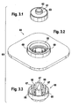
- Fig. 3 , 2 shows an integrally formed, provided with a surface area membrane part 64, which also has a boundary 65 of an opening on its upper side.
- Fig. 3.3 is a lower part 66 of the inventively proposed controller assembly 60 for an electropneumatic pressure transducer to refer, which has a plurality of spaced apart by gaps 68 web surfaces 67.
- controller assembly 60 can be manufactured as easily manufacturable injection molded parts, resulting in a simple structure controller assembly 60 results, which requires few components, ensures easy installation and identical functionality compared to the in the Fig. 2 and 2.1 ensured, consisting of a variety of items governor assembly guaranteed.
- Fig. 4 is a cross section through a cohesively joined regulator assembly, an upper part, a one-piece planar membrane part and a lower part comprising, removable.
- FIG. 4 shows that the upper part 61 is inserted into the boundary 65 of the flat membrane part 64.
- the lower edge of the upper part 61 rests on the bottom of the boundary 65 of the one-piece membrane part 64.
- the upper part 61 lies on the web surfaces 67, which in turn are separated by gaps 68, on.
- the web surfaces 67 enforce in Fig. 4 not shown openings 69 in the bottom of the membrane part 64, which lie within the boundary 65.
- the flat, one-piece membrane part 64 in turn abuts in the lower part 66 of the controller assembly. Between a sealing ring 70 and the membrane part 64, a sealing region 72 is formed, forming a line contact 73.
- the web surfaces 67 pass through openings 69 in the bottom of the membrane part 64 and can be firmly bonded to the underside of the upper part 61 at materially joined joints 74, for example by means of the ultrasonic welding process.
- the one-piece, flat-shaped membrane part 64 furthermore has underneath the opening 62 a plane surface designated by reference numeral 71.
- a lower boundary of the opening 62 forms with the flat surface 71 of the one-piece, flat membrane part 64 a sealing surface 70 in the operation of the controller assembly 60, whose individual parts in the Fig. 3.1, 3.2 and 3.3 are shown.
- Fig. 5 shows the use of the inventively proposed controller assembly according to the Fig. 3 , 1 . 3 , 2 . 3.3 and 4 on an electropneumatic converter.
- the in Fig. 5 shown electro-pneumatic transducer 30 includes the housing 31, in which the magnetic core 58 enclosing the magnetic coil 37 is arranged. At the bottom of the housing 31, the filter cartridge 38 is located above an opening with the atmospheric pressure p ATM .
- the regulator assembly 60 comprising the upper part 61, the one-piece, two-dimensional membrane 64 and the lower part 66 is arranged.
- the upper part 61 of the controller assembly 60 encloses a port 84, which is acted upon by the supply vacuum p V.
- Below the one-piece membrane part 64 formed with a crowned region is the magnetic core 35, which in turn is enclosed by an armature guide and the magnet coil 37.
- the magnetic core 35 includes a sawtooth profiling 83, with which this passes through the lower part 66 of the controller assembly 60.
- the one-piece, flat-shaped membrane part 64 has on its outer circumference clamping points 89, via which the membrane part 64 is clamped in the housing 31 after the assembly of a cover element 87 of the electropneumatic transducer 30.
- the magnetic core 35 comprises a profiling 80, which cooperates with a magnet armature profiling 81 of the magnet armature of the electropneumatic converter 30.
- the armature is traversed by a through hole 88.
- the housing 31 of the electropneumatic converter 30 has snap-locks 86, to which the cover element 87 can be latched.
- a plug connection 85 for contacting the magnetic coil 37, for example via a ram contact.
- the electrical interface marking position 85 can be occupied, for example, via a FCI connector contact.
- an upper part 61, a one-piece, flat membrane part 64 and a lower part 66 can considerably simplify the construction of the control range of the electropneumatic pressure transducer 30.
- the components 61, 64 and 66 of the controller assembly 60 can be manufactured as easy to manufacture plastic injection molded components and are inserted before mounting the lid member 87 of the electropneumatic converter 30 in this.
- a control range of a known from the prior art electro-pneumatic converter can be circumvented by using the inventively proposed controller assembly 60. This can be a considerable simplification reach the assembly of the electropneumatic pressure transducer. Furthermore, the spring elements 47, 48 and 49 can now be omitted. In particular, the requirement that the first membrane part 45 according to FIG Fig. 2 , 1 via the spring element 47 to the sealing rubber 47, which is received in the valve cap 43, hire.
- a seal between inserted into the valve cap 43 rubber seal and the through hole 39 can be achieved by the inventively proposed controller assembly 60 through the sealing surface 70, which is the integral joining of the upper part 61 with the lower part 66 with intermediate storage of the integral membrane 64 on the flat surface 71 of the integral diaphragm part sets by itself.
- Fig. 5 indicated arrow, which shows the path of the air through the electropneumatic pressure transducer 30, the air flows through the atomosphere side facing the opening via the filter insert 38 into a gap 82 which between the outside of the solenoid 37 and the inside of the housing 31 is formed.
- the air flows along the sawtooth profile 83 past the magnetic core 35 and along the openings 69 into the chamber above the regulator assembly 60.
Landscapes
- Engineering & Computer Science (AREA)
- General Engineering & Computer Science (AREA)
- Mechanical Engineering (AREA)
- Physics & Mathematics (AREA)
- Fluid Mechanics (AREA)
- General Physics & Mathematics (AREA)
- Automation & Control Theory (AREA)
- Magnetically Actuated Valves (AREA)
- Supercharger (AREA)
Description
- Elektropneumatische Druckwandler werden in Kraftfahrzeugen eingesetzt und erlauben die Bereitstellung eines zwischen einem Umgebungsdruck und einem vorgebbaren Unterdruck liegenden Verbraucherdruckes (Verbraucherunterdruck). Die Höhe des Verbraucherdruckes wird in der Regel über einen Steuerstrom eingestellt, mit dem ein Spulenkörper eines Magnetventiles des elektropneumatischen Druckwandlers beaufschlagt wird. Mittels elektropneumatischen Druckwandler können Klappensteller im Ansaugtraktbereich oder im Abgastrakt einer Verbrennungskraftmaschine angesteuert werden.
-
DE 195 00 567.8 offenbart einen elektropneumatischen Druckwandler. Eine dem Steuerstrom, mit welchem ein Spulenkörper eines Magnetventils beaufschlagt wird, proportionale Magnetkraft, hält einen Anker gegen einen Dichtsitz, der einen mit dem Umgebungsdruck verbundenen Anschluss von einem Anschluss abdichtet, an dem der Verbraucherdruck anliegt. Bei stromlosem Zustand des Magnetventiles ist der Dichtsitz geschlossen. Dabei ist von Nachteil, dass systemimmanente Undichtigkeiten zwischen einem mit dem Unterdruck beaufschlagbaren Anschluss und dem den Verbraucherdruck aufweisenden Anschluss auftreten können. An diesem liegt im stromlosen Zustand des Magnetventiles ein relativ großer Verbraucherunterdruck an. -
DE 196 23 960 A1 bezieht sich ebenfalls auf einen elektropneumatischen Druckwandler. Der offenbarte elektropneumatische Druckwandler umfasst ein Magnetventil, das eine Magnetspule sowie einen, gegen einen Dichtsitz bildenden Anschlag verschiebbar geführten Anker aufweist. Der Anker ist mittels eines biegeelastischen Halterelementes gehalten. Im stromlosen Zustand der Magnetspule des Magnetventiles ist der Anker in einem Abstand zu dem Anschlag gehalten, derart, dass sich ein Ringspalt zwischen einem mit Umgebungsdruck beaufschlagbaren Bereich und einem mit Unterdruck beaufschlagbaren Bereich des elektropneumatischen Druckwandlers ergibt. Der Ringspalt kann mittels des biegeelastisch ausgebildeten Halteelementes eingestellt werden. Eine den Anker in der Horizontalen haltende Federkraft des Halteelementes ist größer bemessen als eine senkrecht auf den Anker wirkende Federkraft eines den Anker in Richtung des Anschlages drückenden Federelementes. -
DE 195 45 532 A1 bezieht sich auf eine Halte- und Führungseinheit für ein Sperrorgan eines Solenoidventils und ein Verfahren zu ihrer Herstellung. Es wird eine Halte- und Führungseinheit offenbart, die dreiteilig ausgebildet ist und ein Ringelement, ein topfförmiges Element und ein Sperrorgan umfasst. Dabei ist das Sperrorgan zwischen dem Ringelement und dem Boden des topfförmigen Elementes in einem Ringsitz eingeklemmt. - Gemäß der aus dem Stande der Technik bekannten Lösungen, werden ein Membranteil und ein Ventilhutteil eines Reglers des elektropneumatischen Druckwandlers als getrennte Bauteile ausgebildet. Diese werden mittels Druckfedern, die sich an Gehäuse und Deckelelement des elektropneumatischen Druckwandlers abstützen und eine Verpressung zwischen dem Gehäuse und dem Deckelelement fixiert. Die Auslegung der Druckfedern und die Federeigenschaften des Membranteiles bestimmen den Arbeitshub des Membrandeckels sowie des Ventilhutes im Regelbetrieb des elektropneumatischen Druckwandlers. Sowohl der Ventilhut als auch das Membranteil werden im Zweikomponentenspritzgießverfahren hergestellt. Hierbei liegen die Werkzeugkosten sehr hoch. Ein weiterer Nachteil der aus dem Stand der Technik bekannten Lösungen, stellt die Montage des Regelteiles im Gehäuse des elektropneumatischen Druckwandlers sowie den dazugehörigen Federelementen dar, die sehr aufwändig ist.
- Mit der erfindungsgemäßen Lösung kann das Reglerteil eines elektropneumatischen Druckwandlers erheblich vereinfacht werden. Die Funktionen des aus dem Stande der Technik bekannten Ventilhutes und der zweiteiligen Membran kann von einer Regler-Baugruppe übernommen werden, die einfach herstellbare Spritzgussbauteile umfasst und lediglich ein Druckfederelement benötigt.
- Damit lassen sich durch Einsatz wenigerer Bauteile einerseits eine einfache Montage der erfindungsgemäß vorgeschlagenen Regler-Baugruppe eines elektropneumatischen Druckwandlers unter andererseits gleicher Funktionalität des elektropneumatischen Druckwandlers realisieren. Die Regler-Baugruppe umfasst drei Bauteile, nämlich ein Oberteil, ein einstückig ausgebildetes Membranteil sowie ein Unterteil, wobei das Unterteil mit Stegflächen ausgebildet ist. Diese Bauteile der Regler-Baugruppe eines elektropneumatischen Druckwandlers lassen sich getrennt im Wege des Kunststoffspritzgießverfahrens herstellen. Die genannten Bauteile der Regler-Baugruppe werden nach dem Herstellen im Wege des Kunststoffspritzgießverfahrens gefügt. Nach dem Fügevorgang können das Ober- und das Unterteil der Regler-Baugruppe mittels eines stoffschlüssigen Fügeverfahrens wie beispielsweise dem Ultraschallschweißen miteinander verschweißt werden. Bei dem Verschweißen des Ober- und des Unterteiles der Regler-Baugruppe mit dem einstückig ausgebildeten Membranteil werden an der zwischengelagerten Membran mehrere Dichtstellen erzeugt, welche die Funktionalität der Regler-Braugruppe des erfindungsgemäß vorgeschlagenen elektropneumatischen Druckreglers realisieren. Die Regler-Baugruppe umfasst ein Oberteil mit einer eine Durchgangsöffnung begrenzenden Umrandung, die mit einer Planfläche des einstückig ausgebildeten Membramteils eine Dichtfläche ausbildet. Das einstückig ausgebildete Membranteil, umfasst ebenfalls eine Öffnung berandenden ringförmig ausgebildeten Steg, in welchem das Oberteil aufgenommen werden kann. Das Unterteil, welches in der erfindungsgemäß vorgeschlagenen Regler-Baugruppe zum Einsatz kommt, umfasst mehrere durch Zwischenräume voneinander getrennte stegförmige Flächen.
- Neben dem stoffschlüssigen Fügeverfahren, wie dem Ultraschall-Schweißverfahren, kann eine stoffschlüssige Verbindung zwischen dem Oberteil und dem Unterteil der erfindungsgemäß vorgeschlagenen Regler-Baugruppe für einen elektropneumatischen Druckwandler, auch im Wege des Laserschweißens oder anderer stoffschlüssiger Verfahren hergestellt werden.
- Anhand der Zeichnung wird die Erfindung nachstehend eingehender erläutert.
- Es zeigt:
- Figur 1
- den Einsatz elektropneumatischer Druckwandler zur Ansteuerung von Klappensteller im Ansaug- bzw. Abgastrakt von Verbrennungskraftmaschinen,
- Figur 2
- den schematischen Aufbau eines aus dem Stande der Technik bekannten elektropneumatischen Druckwandlers,
- Figur 2.1
- eine Detailansicht der Regler-Baugruppe eines aus dem Stande der Technik bekannten elektropneumatischen Druckwandlers gemäß der Darstellung in
Fig. 2 , - Figuren 3.1, 3,2, 3,3
- die Einzelteile einer erfindungsgemäß vorgeschlagenen Regler-Baugruppe eines elektropneumatischen Druckwandlers,
- Figur 4
- einen Querschnitt durch eine mittels eines stoffschlüssigen Fügeverfahrens gefügte Regler-Baugruppe, ein Oberteil, ein einstückiges Membranteil sowie ein Unterteil umfassend und
- Figur 5
- den Einsatz der erfindungsgemäß vorgeschlagenen Regler-Baugruppe gemäß
Fig. 4 an einem elektropneumatischen Druckwandler. - Der Darstellung gemäß
Fig. 1 ist die Anordnung von elektropneumatischen Druckwandlern im Ansaug- bzw. Abgastrakt einer Verbrennungskraftmaschine zu entnehmen. In der Darstellung gemäßFig. 1 ist eine Verbrennungskraftmaschine 1 dargestellt, die über einen Hochdruckspeicherraum 4 (Common-Rail) mit Kraftstoff versorgt wird. Der Zylinderkopfbereich der Verbrennungskraftmaschine 1 ist durch Bezugszeichen 2 gekennzeichnet; der Hochdrucksammelraum 4 zur Aufnahme von Kraftstoff wird über ein Hochdruckförderaggregat 3 mit aus einem Kraftstofftank 5 geförderten Kraftstoff beaufschlagt. Das Hochdruckförderaggregat 3 beaufschlagt den Hochdrucksammelraum 4 mit unter extrem hohem Druck stehenden Kraftstoff. - Vom Druckspeicher 4 (Common-Rail) strömt der Kraftstoff über Hochdruckanschlüsse 6 einzelnen, entsprechend der Anzahl der mit Kraftstoff zu versorgenden Brennräume 8 der Verbrennungskraftmaschine 1 vorgesehenen Kraftstoffinjektoren 7 zu. Der Kraftstoffinjektor 7 ist im Zylinderkopfbereich 2 der Verbrennungskraftmaschine 1 derart angeordnet, dass die Einspritzöffnungen in den Brennraum 8 zwischen Einlassventilen 11 und Auslassventilen 12 liegen. An das Auslassventil 12 schließt sich eine Abgasleitung 13 an, während am Einlassventil oder den Einlassventilen 11 eine Ansaugluftleitung angeschlossen ist. In der Abgasleitung 13 der Verbrennungskraftmaschine 1 kann eine Ladeeinrichtung 14 angeordnet werden, die als Turbolader ausgebildet sein kann. In der Abgasleitung 13 ist ein Abgasrückführventil 15 vorgesehen, welches mittels eines ersten Stellers 16 betätigbar ist. Der erste Steller 16 wiederum ist über einen ersten elektropneumatischen Wandler 17 betätigbar. Über die Abgasleitung 13 strömt einem Laufrad 18 der Ladeeinrichtung 14 Abgas zu. In der Abgasleitung 13 ist weiterhin ein erster Ladedrucksteller 19 aufgenommen, mit der die Ladeeinrichtung 14 beaufschlagt wird beeinflussbar ist. Der erste Ladedrucksteller 19 seinerseits ist über einen zweiten elektropneumatischen Wandler 20 betätigbar. Der Ladeeinrichtung 14 ist darüber hinaus ein weiterer, zweiter Ladedrucksteller 21 zugeordnet, welcher ebenfalls über den zweiten elektropneumatischen Wandler 20 betätigbar ist. Das Laufrad 18 der Ladeeinrichtung 14 treibt ein Verdichterrad an, mit welchem Frischluft verdichtet wird und einem Ladeluftkühler 22 zugeführt wird. Parallel zum Ladeluftkühler 22 erstreckt sich in der Ansaugleitung der Verbrennungskraftmaschine ein Bypass 23, in welchem ein Bypass-Klappensteller 24 aufgenommen ist, der seinerseits durch einen dritten elektropneumatischen Wandler 25 betätigbar ist. Zwischen der Ausgangsseite des Ladeluftkühlers 22 und der Mündungsstelle des Bypasses 23 in die Ansaugleitung ist ein Regelklappensteller 26 integriert, welcher seinerseits über einen vierten elektropneumatischen Wandler 27 angesteuert wird.
- Die in
Fig. 1 dargestellten elektropneumatischen Wandler 17, 20, 25 und 27 werden häufig, wie aus der Darstellung gemäßFig. 1 hervorgeht im Ansaugtrakt- bzw. Abgastrakt einer Verbrennungskraftmaschine 1 eingesetzt. Elektropneumatische Wandler 17, 20, 25 und 27 können auch zur Betätigung von Swirl-Klappen und zur Kanalabschaltung im Saurohr eingesetzt werden, wenn pneumatische und proportionale Stellvorgänge erforderlich werden. -
Fig. 2 ist der schematische Aufbau eines aus dem Stande der Technik bekannten elektropneumatischen Wandlers zu entnehmen. - Aus der Darstellung gemäß
Fig. 2 geht hervor, dass der dort dargestellte elektropneumatische Wandler 30 ein Gehäuse 31 umfasst. In das Gehäuse 31 ist im Bereich einer Öffnung zum Zuführen des Atmosphärendruckes pATM ein scheibenförmiges Filterelement 38 eingelassen. Das Gehäuse 31 ist durch ein Deckelteil 33 verschlossen. Im Gehäuse 31 ist ein Magnettopf 36 aufgenommen, in welchen eine Magnetspule 37 eingelassen ist. Der Magnettopf 36 ist gegen das Gehäuse 31 an dessen Unterseite über eine Dichtung 34 abgedichtet. Die Magnetspule 37 umschließt einen Magnetkern 35, welcher eine Durchgangsbohrung aufweist. Im Deckelteil 33 des elektropneumatischen Wandlers 30 gemäßFig. 2 ist ein Filterelement 32 in einen Stutzenanschluss eingelassen, an dem ein variabler Verbraucherunterdruck pVAR anliegt. Im Deckelteil 33 des elektropneumatischen Wandlers 30 gemäßFig. 2 befindet sich ferner ein Anschlussstutzen für eine Unterdruckquelle, die einen Versorgungsunterdruck pV bereitstellt. - Der Darstellung gemäß
Fig. 2 .1 ist die Regler-Baugruppe des elektropneumatischen Wandlers gemäßFig. 2 in vergrößertem Maßstab zu entnehmen. - Aus der Darstellung gemäß
Fig. 2 .1 geht hervor, dass im Deckelteil 33 eine Bohrung 39 ausgebildet ist. An der Bohrung liegt der Versorgungsunterdruck pV an. Das Deckelteil 33 umschließt ein erstes Membranteil 45,welches an einer Koppelstelle 50 mit einem weiteren, zweiten Membranteil 51 verbunden ist. In das erste Membranteil 45 ist eine Drosselöffnung 44 eingelassen. Zwischen der Innenseite des Deckelteiles 33 und dem Halsbereich des ersten Membranteiles 45 befindet sich ein erstes Federelement 47. Das Membranteil 45 umschließt seinerseits einen Ventilhut 43, der sich an einem Joch 42 über ein drittes Federelement 49 abstützt. Das Joch 42 ist wiederum durch ein zweites Federelement 48 oberhalb einer Ankerplatte 41 abgestützt. Der Ventilhut 43 weist einen Dichtgummi 46 auf, auf welchem sich der Halsbereich des ersten Membranteiles 45 abstützt. An einer Koppelstelle 50 sind das erste Membranteil 45 und ein weiteres, zweites Membranteil 51 miteinander verbunden. Unterhalb der Ankerplatte 41 ist eine Gummiplatte 40 aufgenommen, welche einer Stirnseite des Magnetkernes 35 gegenüberliegt. Der Magnetkern 35 seinerseits ist von einer in der Detailansicht gemäßFig. 2 .1 nur teilweise dargestellten Magnetspule 37 umgeben. - Aus der Darstellung gemäß
Fig. 2 .1 geht hervor, dass die dort dargestellte Regler-Baugruppe im oberen Bereich des elektropneumatischen Wandlers 30 allein drei Federelemente 47, 48, 49 erfordert, was hinsichtlich der Montage sehr aufwändig ist, ferner sind eine Vielzahl von Bauteilen 45, 51 hinsichtlich der Membran, der Ventilhut 43, der Dichtgummi 46, die erwähnten Federn 47, 48, 49 erforderlich, was hinsichtlich der Montage einen weiteren nur schwierig zu automatisierenden Prozess erfordert. - Den Darstellungen gemäß der
Fig. 3 .1 ,3 .2 ,3.3 sind Einzelteile der erfindungsgemäß vorgeschlagenen Regler-Baugruppe für einen elektropneumatischen Wandler entnehmbar. Eine Reglerbaugruppe 60 umfasst ein Oberteil 61, welches eine Durchgangsöffnung 62 aufweist. Die Durchgangsöffnung 62 ist von einer Berandung 63 umschlossen.Fig. 3 .2 zeigt ein einstückig ausgebildetes, mit einem Flächenbereich versehenes Membranteil 64, welches an seiner Oberseite ebenfalls eine Berandung 65 einer Öffnung aufweist.Fig. 3.3 ist ein Unterteil 66 der erfindungsgemäß vorgeschlagenen Regler-Baugruppe 60 für einen elektropneumatischen Druckwandler zu entnehmen, welches mehrere voneinander durch Zwischenräume 68 getrennte Stegflächen 67 aufweist. - Die in den
Fig. 3 .1 ,3 .2 sowie 3.3 dargestellten Einzelteile der erfindungsgemäß vorgeschlagenen Regler-Baugruppe 60 lassen sich als einfach herstellbare Spritzgussteile fertigen, wodurch sich eine einfach aufgebaute Regler-Baugruppe 60 ergibt, die wenige Bauteile erfordert, eine einfache Montage gewährleistet und eine identische Funktionalität im Vergleich zu der in denFig. 2 und 2.1 dargestellten, aus einer Vielzahl von Einzelteilen bestehenden Regler-Baugruppe gewährleistet. -
Fig. 4 ist ein Querschnitt durch eine stoffschlüssig gefügte Regler-Baugruppe, ein Oberteil, ein einstückiges flächiges Membranteil sowie ein Unterteil umfassend, entnehmbar. - Aus der Darstellung gemäß
Fig. 4 geht hervor, dass das Oberteil 61 in die Berandung 65 des flächigen Membranteiles 64 eingesetzt wird. Der untere Rand des Oberteiles 61 liegt auf dem Grund der Berandung 65 des einstückigen Membranteiles 64 an. Das Oberteil 61 liegt auf den Stegflächen 67, die ihrerseits durch Zwischenräume 68 getrennt sind, auf. Die Stegflächen 67 durchsetzen inFig. 4 nicht dargestellte Öffnungen 69 im Boden des Membranteiles 64, welche innerhalb der Berandung 65 liegen. - Das flächig ausgebildete, einstückige Membranteil 64 liegt seinerseits im Unterteil 66 der Regler-Baugruppe an. Zwischen einem Dichtring 70 und dem Membranteil 64 stellt sich unter Ausbildung eines Linienkontaktes 73 ein Dichtbereich 72 ein. Die Stegflächen 67 durchsetzen Öffnungen 69 im Boden des Membranteiles 64 und sind an stoffschlüssigen Fügestellen 74, beispielsweise im Wege des Ultraschallschweißverfahrens mit der Unterseite des Oberteiles 61 stoffschlüssig verbindbar.
- Das einstückig, flächige ausgebildete Membranteil 64 weist darüber hinaus unterhalb der Öffnung 62 eine mit Bezugszeichen 71 bezeichnete Planfläche auf. Eine untere Berandung der Öffnung 62 bildet mit der Planfläche 71 des einstückig, flächig ausgebildeten Membranteiles 64 einen Dichtfläche 70 im Betrieb der Regler-Baugruppe 60, deren Einzelteile in den
Fig. 3.1, 3.2 und 3.3 dargestellt sind. - Die entsprechend der Darstellung in
Fig. 3.3 gekrümmt ausgebildeten Stegflächen 67 greifen mit ihren oberen Enden in eine umlaufende Nut des Oberteiles 61 ein. Die Stegfläche 67 ragen durch die Öffnungen 69 im Boden des Membranteils 64 hindurch. Dadurch wird das Fügen der Regler-Baugruppe 60, das Oberteil 61, die einstückige Membran 64 sowie das Unterteil 66 umfassend, erheblich vereinfacht. Neben dem stoffschlüssigen Fügen des Oberteiles 61 mit dem Unterteil 66 unter Zwischenschaltung des flächig, einstückig ausgebildeten Membranteiles 64 im Wege des Ultraschall-Schweißverfahrens können auch andere stoffschlüssige Fügeverfahren, wie zum Beispiel Reibschweißen, Laserstrahlschweißen und dergleichen eingesetzt werden. Nach dem Fügen der Komponenten 61, 64 und 66 der erfindungsgemäß vorgeschlagenen Regler-Baugruppe 60 können nach dem Fügevorgang automatisiert stoffschlüssig miteinander verbunden werden, wobei die stoffschlüssigen Verbindungsstellen 74 aufgrund der zwischen dem Oberteil 61 und dem Untereil 66 zwischengelagerten Membran 64 Dichtbereiche 70 bzw. 72 erzeugen. -
Fig. 5 zeigt den Einsatz der erfindungsgemäß vorgeschlagenen Regler-Baugruppe gemäß derFig. 3 .1 ,3 .2 ,3.3 sowie 4 an einem elektropneumatischen Wandler. - Der in
Fig. 5 dargestellte elektropneumatische Wandler 30 umfasst das Gehäuse 31, in welchem die den Magnetkern 65 umschließende Magnetspule 37 angeordnet ist. An der Unterseite des Gehäuses 31 befindet sich der Filtereinsatz 38 oberhalb einer mit dem Atmosphärendruck pATM befindlichen Öffnung. - Im oberen Bereich des elektropneumatischen Wandlers ist die aus dem Oberteil 61, der einstückig, flächig ausgebildenden Membran 64 und das Unterteil 66 umfassende Regler-Baugruppe 60 angeordnet. Das Oberteil 61 der Regler-Baugruppe 60 umschließt einen Stutzen 84, welcher mit dem Versorgungsunterdruck pV beaufschlagt ist. Unterhalb des mit einem balligen Bereich ausgebildeten einstückigen Membranteiles 64 befindet sich der Magnetkern 35, der seinerseits von einer Ankerführung und der Magnetspule 37 umschlossen ist. Der Magnetkern 35 umfasst eine Sägezahnprofilierung 83, mit welcher dieser das Unterteil 66 der Regler-Baugruppe 60 durchsetzt. Das einstückig, flächig ausgebildete Membranteil 64 weist an seinem Außenumfang Einspannstellen 89 auf, über welche das Membranteil 64 nach der Montage eines Deckelelementes 87 des elektropneumatischen Wandlers 30 im Gehäuse 31 eingespannt wird.
- Der Magnetkern 35 umfasst eine Profilierung 80, welche mit einer Magnetankerprofilierung 81 des Magnetankers des elektropneumatischen Wandlers 30 zusammenwirkt. Der Magnetanker ist von einer Durchgangsbohrung 88 durchzogen. Das Gehäuse 31 des elektropneumatischen Wandlers 30 weist Schnappverschlüsse 86 auf, an welchen das Deckelelement 87 verrastbar ist. Im unteren Bereich des Gehäuses 31 des elektropneumatischen Wandlers 30 befindet sich ein Steckeranschluss 85 zur Kontaktierung der Magnetspule 37, beispielsweise über einen Rammkontakt. Die die elektrische Schnittstelle markierende Position 85 kann beispielsweise auch über einen FCI-Stecker Kontakt belegt werden.
- Aus der Darstellung gemäß
Fig. 5 geht hervor, dass durch den Einsatz eine erfindungsgemäß vorgeschlagene Regler-Baugruppe 60, ein Oberteil 61, ein einstückiges, flächiges Membranteil 64 sowie ein Unterteil 66 enthaltend, eine erhebliche Vereinfachung des Aufbaus des Regel-Bereiches des elektropneumatischen Druckwandlers 30 erreicht werden kann. Die Komponenten 61, 64 und 66 der Regler-Baugruppe 60 können als einfach herzustellende Kunststoffspritzgussbauteile gefertigt werden und vor Montage des Deckelelementes 87 des elektropneumatischen Wandlers 30 in diesen eingelegt werden. Eine Anordnung von Federelementen 47, 48, 49 zum Vorspannen der Membranteile 45, 51 sowie zum Vorspannen des Ventilhutes 43 sowie separate Dichtflächen 40, 46 gemäß der Darstellung inFig. 2 .1 eines Regel-Bereiches eines aus dem Stand der Technik bekannten elektropneumatischen Wandlers, können durch Einsatz der erfindungsgemäß vorgeschlagenen Regler-Baugruppe 60 umgangen werden. Damit lässt sich eine erhebliche Vereinfachung der Montage des elektropneumatischen Druckwandlers erreichen. Ferner können die Federelemente 47, 48 sowie 49 nunmehr entfallen. Insbesondere entfällt das Erfordernis, das erste Membranteil 45 gemäßFig. 2 .1 über das Federelement 47 an den Dichtgummi 47, der im Ventilhut 43 aufgenommen ist, anzustellen. Eine Abdichtung zwischen in den Ventilhut 43 eingelassenen Dichtgummi und der Durchgangsbohrung 39 lässt sich durch die erfindungsgemäß vorgeschlagene Regler-Baugruppe 60 durch den Dichtfläche 70 erzielen, der sich beim stoffschlüssigen Fügen des Oberteiles 61 mit dem Unterteil 66 unter Zwischenlagerung der einstückigen Membran 64 auf der Planfläche 71 des einstückigen Membranteiles von selbst einstellt. - Wie dem Verlauf des in
Fig. 5 eingetragenen Pfeiles, welcher den Weg der Luft durch den elektropneumatischen Druckwandler 30 zeigt, entnommen werden kann, strömt die Luft durch die der Atmösphärenseite zugewandte Öffnung über den Filtereinsatz 38 in einen Spalt 82 ein, welcher zwischen der Außenseite der Magnetspule 37 und der Innenseite des Gehäuses 31 ausgebildet ist. Die Luft strömt entlang des Sägezahnprofiles 83 am Magnetkern 35 vorbei und entlang der Öffnungen 69 in die Kammer oberhalb der Reglerbaugruppe 60. -
- 1
- Verbrennungskraftmaschine
- 2
- Zylinderkopfbereich
- 3
- Hochdruckaggregat
- 7
- Kraftstoffinjektor
- 8
- Brennraum
- 9
- Kolben
- 10
- Zylinder
- 15
- Abgasrückführventil
- 16
- 1. Steller
- 17
- 1. elektropneumatischer Wandler
- 19
- 1. Ladedrucksteller
- 20
- 2. elektropneumatischer Wandler
- 21
- 2. Ladedrucksteller
- 22
- Ladeluftkühler
- 23
- Bypass-Leitung
- 24
- Bypass-Klappensteller
- 25
- 3. elektropneumatischer Wandler
- 26
- Regelklappensteller
- 27
- 4. elektropneumatischer Wandler
- 30
- Elektropneumatischer Wandler
- 31
- Gehäuse
- 32
- Filterelement
- 33
- Deckelteil
- PATM
- Umgebungsdruck
- 34
- Dichtung
- 35
- Magnetkern
- 36
- Magnettopf
- 37
- Magnetspule
- 38
- Filtereinsatz
- pVar
- Mischdruck
- PV
- Unterdruckversorgung
- 72
- Dichtbereich
- 73
- Linienkontakt
- 74
- Stoffschlüssige Fügestelle
- 80
- Magnetkern-Profilierung
- 81
- Magnetanker-Profilierung
- 82
- Spalt
- 83
- Sägezahnprofil
- 84
- Stutzen
- 85
- Steck-Anschluss
- 86
- Schnappverschluss-Deckelelement
- 87
- Deckelelement
- 88
- Durchgangsbohrung
- 89
- Einspannstelle
- 90
- umlaufende Ausnehmung
- 39
- Durchgangsbohrung
- 40
- Gummiplatte
- 41
- Ankerplatte
- 42
- Joch
- 43
- Ventilhut
- 44
- Drosselstelle
- 45
- 1. Membranteil
- 46
- Dichtgummi
- 47
- 1. Federelement
- 48
- 2. Federelement
- 49
- 3. Federelement
- 50
- Koppelstelle
- 51
- 2. Membranteil
- 60
- Regler-Baugruppe
- 61
- Oberteil
- 62
- Öffnungen
- 63
- Berandung
- 64
- einstückiges Membranteil
- 65
- Berandung
- 66
- Unterteil
- 67
- Stegfläche
- 68
- Zwischenraum
- 69
- Durchgangsöffnungen im Membranteil (64)
- 70
- Dichtfläche (im Betrieb)
- 71
- Planfläche Membranteil (64)
Claims (8)
- Elektropneumatischer Druckwandler (30) mit einem Magnetventil, welches eine Magnetspule (37) und einen Magnetkern (35) aufweist, die in einem Gehäuse (31) aufgenommen sind, sowie eine Regler-Baugruppe (60), mit welcher ein variabler Unterdruck pVar von Verbrauchern (16, 19, 21, 24) regelbar ist, dadurch gekennzeichnet, dass die Regler-Baugruppe (60) unter Ausbildung von Dichtstellen (70, 72) stoffschlüssig miteinander gefügte Bauelemente (61, 64, 66) aufweist, wobei die miteinander gefügten Bauteile als Oberteil (61), als einstückiges Membranteil (64) sowie als ein Unterteil (66) mit Stegflächen (67) ausgebildet sind, wobei das einstückige Membranteil (64) eine Planfläche (71) aufweist, die mit einer Berandung (63) einer Öffnung (62) des Oberteiles (61) eine Dichtfläche (70) ausbildet.
- Elektropneumatischer Wandler gemäß Anspruch 1, dadurch gekennzeichnet, dass die Bauelemente (61, 64, 66) der Regler-Baugruppe (60) jeweils getrennt voneinander herstellbare Spritzgussbauteile sind.
- Elektropneumatischer Wandler gemäß Anspruch 1, dadurch gekennzeichnet, dass die Stegflächen (67) Öffnungen (69) im einstückigen Membranteil (64) durchgreifen und am Oberteil (61) arretierbar sind.
- Elektropneumatischer Wandler gemäß Anspruch 1, dadurch gekennzeichnet, dass das Unterteil (66) das einstückige Membranteil (64) unter Ausbildung eines Dichtbereiches (72) linienförmig (73) kontaktiert.
- Elektropneumatischer Wandler gemäß Anspruch 1, dadurch gekennzeichnet, dass das einstückige Membranteil (64) eine dessen Bodenflächen begrenzende Berandung (65) aufweist, in welche das Oberteil (61) eingelassen ist.
- Elektropneumatischer Wandler gemäß Anspruch 1, dadurch gekennzeichnet, dass an der Unterseite des Oberteiles (61) eine umlaufende Ausnehmung (90) ausgebildet ist, in welcher die die Durchgangsöffnungen (69) des einstückigen Membranteiles (64) durchsetzenden Stegflächen (67) des Unterteiles (66) eingreifen.
- Elektropneumatischer Wandler gemäß Anspruch 1, dadurch gekennzeichnet, dass die Bauelemente (61, 66) an Fügestellen (74) derart stoffschlüssig verbunden sind, dass das einstückige Membranteil (64) zwischen diesen angeordnet ist.
- Elektropneumatischer Wandler gemäß Anspruch 6, dadurch gekennzeichnet, dass die Stegflächen (67) des Unterteiles (66) mit der umlaufenden Ausnehmung (90) an einer Unterseite des Oberteiles (61) einen Schnappverschluss bilden.
Applications Claiming Priority (2)
| Application Number | Priority Date | Filing Date | Title |
|---|---|---|---|
| DE10321731A DE10321731A1 (de) | 2003-05-14 | 2003-05-14 | Regler für Elektropneumatische Druckwandler |
| PCT/DE2004/000532 WO2004104461A1 (de) | 2003-05-14 | 2004-03-17 | Regler für elektropneumatische druckwandler |
Publications (2)
| Publication Number | Publication Date |
|---|---|
| EP1625319A1 EP1625319A1 (de) | 2006-02-15 |
| EP1625319B1 true EP1625319B1 (de) | 2008-03-12 |
Family
ID=33394587
Family Applications (1)
| Application Number | Title | Priority Date | Filing Date |
|---|---|---|---|
| EP04721114A Expired - Lifetime EP1625319B1 (de) | 2003-05-14 | 2004-03-17 | Regler für elektropneumatische druckwandler |
Country Status (5)
| Country | Link |
|---|---|
| US (1) | US20070023724A1 (de) |
| EP (1) | EP1625319B1 (de) |
| JP (1) | JP2006526118A (de) |
| DE (2) | DE10321731A1 (de) |
| WO (1) | WO2004104461A1 (de) |
Families Citing this family (5)
| Publication number | Priority date | Publication date | Assignee | Title |
|---|---|---|---|---|
| RU2503868C1 (ru) * | 2012-07-10 | 2014-01-10 | Федеральное государственное унитарное предприятие "Государственный космический научно-производственный центр им. М.В. Хруничева" | Запорное устройство |
| DE102013008686A1 (de) * | 2013-05-22 | 2014-11-27 | Volkswagen Aktiengesellschaft | Schaltsaugrohr |
| DE102015102545B4 (de) | 2015-02-23 | 2017-06-01 | Pierburg Gmbh | Elektropneumatischer Druckwandler |
| DE102015219207B3 (de) * | 2015-10-05 | 2017-02-09 | Conti Temic Microelectronic Gmbh | Druckverteiler für ein Kraftfahrzeug |
| JP1553282S (de) * | 2015-10-30 | 2016-07-04 |
Family Cites Families (11)
| Publication number | Priority date | Publication date | Assignee | Title |
|---|---|---|---|---|
| US3349795A (en) * | 1964-04-22 | 1967-10-31 | Ngk Insulators Ltd | Diaphragm valve including a snap ring connection |
| JPS5960376U (ja) * | 1982-10-15 | 1984-04-20 | 厚木自動車部品株式会社 | 内燃機関の負圧制御バルブ |
| JPS59107377U (ja) * | 1983-01-06 | 1984-07-19 | トヨタ自動車株式会社 | 電磁式負圧制御弁 |
| JPH04290687A (ja) * | 1991-02-07 | 1992-10-15 | Mitsubishi Electric Corp | ダイヤフラム弁 |
| DE4110003C1 (en) * | 1991-03-27 | 1992-07-16 | Pierburg Gmbh, 4040 Neuss, De | Electromagnetic pressure transducer for pneumatic control of motor vehicle - has aperture set by adjustable iron@ core having opening for receiving plunger |
| IT1267646B1 (it) * | 1994-12-12 | 1997-02-07 | Elbi Int Spa | Gruppo di supporto e guida per un otturatore di un'elettrovalvola e procedimento per la fabbricazione, |
| DE19500567B4 (de) | 1995-01-11 | 2006-02-02 | Robert Bosch Gmbh | Magnetventil |
| DE19621221A1 (de) * | 1996-05-25 | 1997-11-27 | Bosch Gmbh Robert | Aggregat und Schnappvorrichtung für ein Aggregat |
| US5979863A (en) * | 1996-11-14 | 1999-11-09 | Hunter Industries, Inc. | Irrigation control valve and screen |
| JP2002286146A (ja) * | 2001-03-26 | 2002-10-03 | Toyoda Gosei Co Ltd | ダイヤフラム弁 |
| US7232106B2 (en) * | 2001-04-04 | 2007-06-19 | Kah Jr Carl | Tilted and stepped diaphragm for control valves |
-
2003
- 2003-05-14 DE DE10321731A patent/DE10321731A1/de not_active Withdrawn
-
2004
- 2004-03-17 JP JP2006508103A patent/JP2006526118A/ja active Pending
- 2004-03-17 DE DE502004006502T patent/DE502004006502D1/de not_active Expired - Lifetime
- 2004-03-17 EP EP04721114A patent/EP1625319B1/de not_active Expired - Lifetime
- 2004-03-17 WO PCT/DE2004/000532 patent/WO2004104461A1/de not_active Ceased
- 2004-03-17 US US10/555,690 patent/US20070023724A1/en not_active Abandoned
Also Published As
| Publication number | Publication date |
|---|---|
| US20070023724A1 (en) | 2007-02-01 |
| JP2006526118A (ja) | 2006-11-16 |
| DE10321731A1 (de) | 2004-12-02 |
| EP1625319A1 (de) | 2006-02-15 |
| WO2004104461A8 (de) | 2005-11-17 |
| WO2004104461A1 (de) | 2004-12-02 |
| DE502004006502D1 (de) | 2008-04-24 |
Similar Documents
| Publication | Publication Date | Title |
|---|---|---|
| US5758865A (en) | Fuel injection valve and engine including the same | |
| EP0778921B1 (de) | Pumpvorrichtung | |
| DE2936425A1 (de) | Elektromagnetisch betaetigbares kraftsoffeinspritzventil | |
| EP0937202A1 (de) | Brennstoffeinspritzventil | |
| DE69808228T2 (de) | Integrierte sammelleitung und entlüftungsventil | |
| DE112012000452T5 (de) | Hochdruckpumpe | |
| EP0840846B1 (de) | Aggregat mit schnappvorrichtung | |
| EP1893855B2 (de) | Bypassventil für verbrennungskraftmaschinen | |
| DE102007059239A1 (de) | Membran, und Hubkolben-Membranpumpe | |
| DE112012003765T5 (de) | Gas-Einspritzdüse mit hoher nach außen gerichteter Strömungsrate für Fahrzeug-Anwendungen | |
| DE4420960A1 (de) | Pumpvorrichtung, insbesondere für ein Tanksystem einer Brennkraftmaschine | |
| WO2000012889A1 (de) | Ventil zum dosierten einleiten von verflüchtigtem brennstoff | |
| US10495232B2 (en) | Dual path dual purge valve system and valve assembly for turbo boosted engine | |
| EP1625319A1 (de) | Regler für elektropneumatische druckwandler | |
| EP2923066A1 (de) | Ventileinrichtung | |
| US8317157B2 (en) | Automobile high pressure pump solenoid valve | |
| DE102011087964A1 (de) | Ventil | |
| JP2003511623A (ja) | 弁制御室内に突入したノズルニードルを備えた、内燃機関に用いられる燃料噴射システムのためのインジェクタ | |
| DE102008001895A1 (de) | Brennstoffeinspritzventil | |
| EP1592880B1 (de) | Kraftstoffeinspritzeinrichtung für eine brennkraftmaschine | |
| EP1328725B1 (de) | Brennstoffeinspritzventil | |
| DE102006003484A1 (de) | Vorrichtung zum Einspritzen von Kraftstoff | |
| DE3231929A1 (de) | Fluessigkeitsfilter | |
| DE3745105C2 (de) | Elektromagnetisches Kraftstoff-Einspritzventil | |
| DE102011017495A1 (de) | Zumesseinheit und Hochdruckpumpe |
Legal Events
| Date | Code | Title | Description |
|---|---|---|---|
| PUAI | Public reference made under article 153(3) epc to a published international application that has entered the european phase |
Free format text: ORIGINAL CODE: 0009012 |
|
| 17P | Request for examination filed |
Effective date: 20051214 |
|
| AK | Designated contracting states |
Kind code of ref document: A1 Designated state(s): DE FR IT |
|
| DAX | Request for extension of the european patent (deleted) | ||
| RBV | Designated contracting states (corrected) |
Designated state(s): DE FR IT |
|
| 17Q | First examination report despatched |
Effective date: 20060726 |
|
| 17Q | First examination report despatched |
Effective date: 20060726 |
|
| GRAP | Despatch of communication of intention to grant a patent |
Free format text: ORIGINAL CODE: EPIDOSNIGR1 |
|
| GRAS | Grant fee paid |
Free format text: ORIGINAL CODE: EPIDOSNIGR3 |
|
| GRAA | (expected) grant |
Free format text: ORIGINAL CODE: 0009210 |
|
| AK | Designated contracting states |
Kind code of ref document: B1 Designated state(s): DE FR IT |
|
| REF | Corresponds to: |
Ref document number: 502004006502 Country of ref document: DE Date of ref document: 20080424 Kind code of ref document: P |
|
| PGFP | Annual fee paid to national office [announced via postgrant information from national office to epo] |
Ref country code: FR Payment date: 20080618 Year of fee payment: 5 |
|
| EN | Fr: translation not filed | ||
| PLBE | No opposition filed within time limit |
Free format text: ORIGINAL CODE: 0009261 |
|
| STAA | Information on the status of an ep patent application or granted ep patent |
Free format text: STATUS: NO OPPOSITION FILED WITHIN TIME LIMIT |
|
| 26N | No opposition filed |
Effective date: 20081215 |
|
| PG25 | Lapsed in a contracting state [announced via postgrant information from national office to epo] |
Ref country code: FR Free format text: LAPSE BECAUSE OF FAILURE TO SUBMIT A TRANSLATION OF THE DESCRIPTION OR TO PAY THE FEE WITHIN THE PRESCRIBED TIME-LIMIT Effective date: 20090102 |
|
| PGFP | Annual fee paid to national office [announced via postgrant information from national office to epo] |
Ref country code: DE Payment date: 20170529 Year of fee payment: 14 |
|
| PGFP | Annual fee paid to national office [announced via postgrant information from national office to epo] |
Ref country code: IT Payment date: 20180322 Year of fee payment: 15 |
|
| REG | Reference to a national code |
Ref country code: DE Ref legal event code: R119 Ref document number: 502004006502 Country of ref document: DE |
|
| PG25 | Lapsed in a contracting state [announced via postgrant information from national office to epo] |
Ref country code: DE Free format text: LAPSE BECAUSE OF NON-PAYMENT OF DUE FEES Effective date: 20181002 |
|
| PG25 | Lapsed in a contracting state [announced via postgrant information from national office to epo] |
Ref country code: IT Free format text: LAPSE BECAUSE OF NON-PAYMENT OF DUE FEES Effective date: 20190317 |