EP1623137B1 - Frein automobile et procede d'actionnement d'un frein automobile - Google Patents
Frein automobile et procede d'actionnement d'un frein automobile Download PDFInfo
- Publication number
- EP1623137B1 EP1623137B1 EP04731149A EP04731149A EP1623137B1 EP 1623137 B1 EP1623137 B1 EP 1623137B1 EP 04731149 A EP04731149 A EP 04731149A EP 04731149 A EP04731149 A EP 04731149A EP 1623137 B1 EP1623137 B1 EP 1623137B1
- Authority
- EP
- European Patent Office
- Prior art keywords
- brake
- detent
- housing
- vehicle brake
- brake piston
- Prior art date
- Legal status (The legal status is an assumption and is not a legal conclusion. Google has not performed a legal analysis and makes no representation as to the accuracy of the status listed.)
- Expired - Lifetime
Links
- 238000000034 method Methods 0.000 title claims description 6
- 230000000903 blocking effect Effects 0.000 claims abstract description 59
- 238000006073 displacement reaction Methods 0.000 claims abstract description 6
- 239000012530 fluid Substances 0.000 claims description 48
- 230000003213 activating effect Effects 0.000 claims description 8
- 230000004913 activation Effects 0.000 claims description 4
- 238000007667 floating Methods 0.000 description 6
- 230000000694 effects Effects 0.000 description 5
- 230000002093 peripheral effect Effects 0.000 description 3
- 230000009471 action Effects 0.000 description 2
- 238000000418 atomic force spectrum Methods 0.000 description 1
- 230000005540 biological transmission Effects 0.000 description 1
- 230000008878 coupling Effects 0.000 description 1
- 238000010168 coupling process Methods 0.000 description 1
- 238000005859 coupling reaction Methods 0.000 description 1
- 238000013016 damping Methods 0.000 description 1
- 230000001404 mediated effect Effects 0.000 description 1
- 230000008569 process Effects 0.000 description 1
- 230000009467 reduction Effects 0.000 description 1
- 230000002441 reversible effect Effects 0.000 description 1
- 238000005096 rolling process Methods 0.000 description 1
- 238000007789 sealing Methods 0.000 description 1
Images


Classifications
-
- F—MECHANICAL ENGINEERING; LIGHTING; HEATING; WEAPONS; BLASTING
- F16—ENGINEERING ELEMENTS AND UNITS; GENERAL MEASURES FOR PRODUCING AND MAINTAINING EFFECTIVE FUNCTIONING OF MACHINES OR INSTALLATIONS; THERMAL INSULATION IN GENERAL
- F16D—COUPLINGS FOR TRANSMITTING ROTATION; CLUTCHES; BRAKES
- F16D55/00—Brakes with substantially-radial braking surfaces pressed together in axial direction, e.g. disc brakes
-
- F—MECHANICAL ENGINEERING; LIGHTING; HEATING; WEAPONS; BLASTING
- F16—ENGINEERING ELEMENTS AND UNITS; GENERAL MEASURES FOR PRODUCING AND MAINTAINING EFFECTIVE FUNCTIONING OF MACHINES OR INSTALLATIONS; THERMAL INSULATION IN GENERAL
- F16D—COUPLINGS FOR TRANSMITTING ROTATION; CLUTCHES; BRAKES
- F16D2121/00—Type of actuator operation force
- F16D2121/18—Electric or magnetic
- F16D2121/24—Electric or magnetic using motors
-
- F—MECHANICAL ENGINEERING; LIGHTING; HEATING; WEAPONS; BLASTING
- F16—ENGINEERING ELEMENTS AND UNITS; GENERAL MEASURES FOR PRODUCING AND MAINTAINING EFFECTIVE FUNCTIONING OF MACHINES OR INSTALLATIONS; THERMAL INSULATION IN GENERAL
- F16D—COUPLINGS FOR TRANSMITTING ROTATION; CLUTCHES; BRAKES
- F16D2125/00—Components of actuators
- F16D2125/18—Mechanical mechanisms
- F16D2125/20—Mechanical mechanisms converting rotation to linear movement or vice versa
- F16D2125/34—Mechanical mechanisms converting rotation to linear movement or vice versa acting in the direction of the axis of rotation
- F16D2125/36—Helical cams, Ball-rotating ramps
-
- F—MECHANICAL ENGINEERING; LIGHTING; HEATING; WEAPONS; BLASTING
- F16—ENGINEERING ELEMENTS AND UNITS; GENERAL MEASURES FOR PRODUCING AND MAINTAINING EFFECTIVE FUNCTIONING OF MACHINES OR INSTALLATIONS; THERMAL INSULATION IN GENERAL
- F16D—COUPLINGS FOR TRANSMITTING ROTATION; CLUTCHES; BRAKES
- F16D2127/00—Auxiliary mechanisms
- F16D2127/06—Locking mechanisms, e.g. acting on actuators, on release mechanisms or on force transmission mechanisms
Definitions
- the invention relates to a vehicle brake with a housing, a brake piston received in the housing, to which a brake pad is attached, and a blocking device, wherein the brake piston is displaceable in the housing via an actuating device and wherein the brake piston can be locked by means of the blocking device with respect to the housing ,
- Such a vehicle brake is from the document DE19945543 known.
- Such a vehicle brake is also from the European patent EP 0 551 397 known.
- a brake piston in a service brake situation, that is, when a coupled to a vehicle brake disc for braking the vehicle wheel to be decelerated, displaced by supplying hydraulic fluid into the fluid chamber relative to the housing and pressed against the brake disc.
- the braking force exerted on the brake disc depends on the size of the hydraulic pressure prevailing in the fluid chamber.
- hydraulic fluid is discharged from the fluid chamber, so that the brake piston with its brake pad can again remove from the brake disk and release it.
- hydraulic fluid can be discharged from the fluid chamber, wherein the Locking rod holds the brake piston in its braking position.
- the hydraulic fluid circuit is thus relieved and the parking brake function of the vehicle brake activated.
- the fluid chamber is filled again with hydraulic fluid until the hydraulic pressure prevailing therein is sufficiently great that the brake piston releases the blocking rod. This can then be moved mechanically to its original position. Subsequently, the hydraulic fluid is discharged from the fluid chamber, so that the brake piston can again take its brems Jerusalem swingsw starting position.
- an electric motor drive is required, whereby the entire arrangement has a relatively complex structure.
- the vehicle electrical system of an automobile is additionally burdened by the required electric motor.
- the blocking device has an electromechanical Verrastungsan extract which is actuated such that it blocks a displacement of the brake piston within the housing in a Verrastungswolf and in a release position the brake piston for movement in the Housing releases.
- this is a locking element arrangement with at least one between one of the locking position associated latching element position and one of the release position associated latching element position displaceable latching element which can be latched by self-locking engagement with a locking element-engaging surface of a drivingly coupled to the brake piston Gegenrastkomponente.
- the at least one locking element is biased in its the release position associated detent element position via a spring element.
- the at least one latching element can be displaced via an electromechanical actuator between its latching position assigned to the latching position and its latching element position assigned to the release position.
- An advantageous development of the invention provides that two locking elements are actuated via the electromechanical actuator, wherein the distance between the locking elements and the pitch of the formed with a plurality of locking element engagement surfaces counter-locking component are matched to one another such that in the locking position, only one of the locking elements is in self-locking engagement with one of the locking element-engaging surfaces and engages the other locking element in each case between two adjacent locking element-attack surfacesshemmungsoko.
- the at least one locking element is formed by a pawl and that the locking element-engaging surfaces of the counter-locking component are designed as locking teeth.
- the at least one latching element may be formed by a latching pin and latching element engagement surfaces of the counter-latching component may be formed as latching pin recesses.
- the brake piston is coupled to a blocking element of the blocking device via a self-releasing thread pairing.
- the self-releasing thread pairing may be formed by an external thread, which is provided on a threaded bolt fastened to the brake piston, and an internal thread, which is provided on a receiving bushing fastened to the blocking element.
- the self-releasing thread pairing is formed by an internal thread provided on the brake piston and an external thread provided on the blocking element.
- the blocking element is drivingly coupled via a transmission device, in particular a planetary gear, with the counter-locking component. It can be provided that the blocking element is rotatably coupled to a sun gear of the planetary gear, further that the counter-locking component is rotatably coupled to a planetary gear of the planetary gear and that the ring gear of the planetary gear is formed in the housing or rotatably coupled thereto.
- the blocking element is rotatably coupled to a planetary gear of the planetary gear
- the counter-locking component is rotatably coupled to a sun gear of the planetary gear and that the ring gear of the planetary gear is formed in the housing or rotatably coupled thereto.
- the planetary gear is formed multi-stage.
- the actuating device may be designed to be hydraulic, wherein the brake piston delimits with the housing a fluid chamber which can be charged with hydraulic fluid via a hydraulic fluid circuit so that the brake piston for actuating the vehicle brake can be displaced hydraulically within the housing along a piston longitudinal axis.
- the actuating device is electromechanical, wherein the brake piston for actuating the vehicle brake by driving an electric motor within the housing along a piston longitudinal axis is displaced.
- a radial bearing arrangement and / or thrust bearing arrangement may be provided.
- the brake piston in a service brake situation, is displaceable by activating the actuator within the housing and that in a parking brake situation, first the brake piston is displaced by driving the actuator within the housing, then the blocking device is actuated and the Brake piston is blocked within the housing and finally the actuator is disabled.
- Actuator be re-activated until the blocking element releases the brake piston and finally the brake piston is returned to its brems decisivsbind initial position.
- the invention further relates to a method for actuating a vehicle brake of the type described above, in which in a service brake situation, the brake piston is displaceable by activating the actuating device within the housing and that in a parking brake situation, first the brake piston is displaced by driving the actuator within the housing, then the blocking device is actuated and the brake piston is blocked within the housing and finally the actuator is deactivated.
- the actuator is activated to resolve the parking brake situation until the blocking element releases the brake piston and finally the brake piston is returned to its brems decisivsquest initial position.
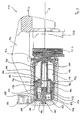
- FIG. 1 a first embodiment of a vehicle brake according to the invention is shown in longitudinal section and generally designated 10.
- the vehicle brake 10 is, as will be explained in detail below, operated electromechanically. It is designed as a disc brake of the floating caliper type.
- the vehicle brake 10 comprises a housing 12 with a floating caliper region 14.
- a first brake pad 16 and a second brake pad 18 are arranged in the floating caliper region 14.
- the two brake pads 16 and 18 are resiliently connected to each other via a Lsymmetric 20, wherein the Lsymmetric 20 tries to urge the two brake pads 16 and 18 apart.
- a brake disc (not shown) is received, which is coupled at its radially inner region with a vehicle wheel also not shown braked.
- the brake pad 18 is slidably mounted on the floating caliper portion 14 of the housing 12 in the direction of the longitudinal axis A. Opposite the brake pad 16 is slidably mounted in the direction of the longitudinal axis A.
- the electrically actuated actuator 24 includes an electric motor 26 and a sebstlösende spindle nut gear assembly 28.
- the electric motor 26 is formed as an internal rotor motor. It comprises a stator 30 which is accommodated in a housing cover 32 fastened to the housing 12. Radially inside the stator 30 is a rotor 34 which has on its radially outer circumferential surface permanent magnets 36, through which it is mechanically driven in the magnetic field established when the stator is energized becomes.
- the rotor 34 is rotatably supported about the axis A via a bearing arrangement 38 on an axial extension 40 of a bearing bush 58 fixed in the housing 12 and thus relative to the housing 12. In its radially inner region of the rotor 34 is rotatably coupled with an externally toothed pin 42. This extends in the axial direction centrally to a planet carrier 44 of a planetary gear 46.
- the planet carrier 44 holds via bearing pin 48 planetary gears 50, wherein the axes of rotation of the bearing pin 48 extend parallel to the longitudinal axis A.
- the planet gears 50 are in engagement with the externally toothed pin 42 at their radially inner area relative to the longitudinal axis A.
- the planet gears 50 engage with a ring gear toothing 52 which is formed on the axial extension of the bearing bush 58.
- the bushing 58 has at its end remote from the internal teeth 52 a flange portion 60, with which it is supported in the axial direction of the housing.
- the planet carrier 44 points to his in Fig. 1 right side a bolt-shaped axial extension 54 which is provided with an external toothing. With this external toothing further planet gears 56 are engaged, which further mesh with the ring gear 52 of the bearing bush 58.
- the planet gears 56 are rotatably supported by bearing bolts 59 on the back of a spindle 64.
- the spindle 64 has on its outer peripheral surface a spiral around the axis A running around guideway 66, in which spherical bearing body 68 are guided.
- the spindle 64 is encompassed by a nut 70, which also has on its inside at least partially a correspondingly spiral-shaped guideway into which also the bearing body 68 engage.
- the spindle 64, the bearing body 68 and the nut 70 form the self-releasing spindle nut gear assembly 28th
- the spindle 64 is mounted in the bearing bush 58 via a sliding bearing arrangement 72. Further, the bushing 58 guides the nut 70 in the direction of the axis A and prevents it from tilting. At the flange portion 60 of the bearing bush 58, a flexible bellows 74 is provided which sealingly cooperates with a lid 76 mounted on the nut 70.
- the rotor 34 is at its in Fig. 1 left area provided with a spur gear teeth 78.
- a locking element 82 can be brought into engagement with the spur toothing 78, so that the rotor 34 is secured against rotation about the longitudinal axis A.
- the locking element 82 and the solenoid 80 are biased into a release position in which they allow rotation of the rotor 34. By energizing the solenoid 80 this moves the locking member 82 in a Verrastungswolf in which this blocks the rotor 34.
- the engagement of the locking element 82 in the spur gear 78 is self-locking, ie it can be solved only by an applied axial force.
- the vehicle brake 10 works in the case of a service brake situation in which a rotating brake disc is to be decelerated, as follows.
- the electric motor 26 When the electric motor 26 is energized, the rotor 34 rotates with low friction about the axis A, due to the bearing arrangement 38.
- the rotation of the rotor 34 first drives the pin 42 and with it the planet wheels 50.
- These roll in the internal teeth 52 of the bearing ring acting as a fixed ring gear 58, so that the planet carrier 44 rotates about the axis A, but with a deviating from the rotational speed of the rotor 34 speed.
- the rotation of the planet carrier 44 is transmitted to the spindle 64 via the axial extension 54 and the planetary gears 56, which also roll in the internal teeth 52 of the bearing ring 58 acting as a stationary ring gear. This rotates within the bearing bush 58 friction. Due to the rotation of the spindle 64 in the bearing bush 58 linearly guided nut 70 is moved in the direction of the longitudinal axis A. This means that the nut 70 is displaced in the direction of the longitudinal axis A due to the two guide tracks of the spindle 64 and the nut 70 mediated by the bearing body 68 in the axial direction and thereby presses on the cover 76 on the brake pad 16.
- the brake pads 16 and 18 act by this pressure force floating on the brake disc 22 and attack on both sides, so that it is braked due to the resulting friction effect. If this braking effect to be reduced or canceled, the electric motor 26 is not energized or energized even with opposite polarity. This leads to a reversible movement of the nut 70 on the spindle 64.
- the circumferential force acting on the locking element can be kept small.
- the lifting magnet 80 is actuated so that it pulls the locking element 82 out of its latched position again. Then, the vehicle brake in their in Fig. 1 move back to the initial position shown.
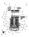
- Fig. 2 is a second embodiment of a vehicle brake according to the invention generally designated 110.
- This comprises a housing 112, in which a brake piston 114 is displaceably guided in the direction of a piston longitudinal axis A.
- the brake piston 114 encloses with the housing 112 a fluid chamber 116 which can be charged with hydraulic fluid via a hydraulic fluid line (not shown) of a hydraulic fluid circuit or can be emptied.
- the guided in the housing 112 brake piston 114 is connected via a bellows 122 at its in Fig. 2 right front end connected to the housing 112, so that the housing interior is shielded against ingress of dirt.
- a brake pad 126 is arranged, which is displaceable in the housing 112.
- the brake pad 126 opposite a second brake pad 128 is disposed, which is also displaceable in the housing 112.
- the pads 126 and 128 are mounted in the housing 112 according to a conventional floating caliper arrangement, so that when the pad 126 is displaced over the brake piston 114, the pad 128 displaces equally, but in the opposite direction. This makes it possible to clamp a not shown, between the brake pads 126 and 128 arranged rotating brake disc between the brake pads 126 and 128 and thus decelerate.
- a threaded bolt 130 is disposed in its radially inner region.
- the threaded bolt 130 is received with its external thread in a receiving threaded bore 132 of a shaft portion of a blocking element 134.
- the internal thread of the female threaded hole 132 in the Blocking element 134 forms together with the external thread of the threaded bolt 130 a self-releasing thread pairing.
- the blocking member 134 further includes a flange 136 which extends radially outward. About the flange 136, the blocking element 134 is supported via a thrust bearing 138 on a shoulder 140 of the housing 112 in the axial direction in Fig. 2 to the left. On the side facing away from the thrust bearing 138 of the flange 136, a plate-shaped spring plate 144 is mounted in the housing 112 via a fixed in the housing 112 retaining ring 142. Between the spring plate 144 and the flange 132, a further thrust bearing 146 is arranged, which lies radially within the range with which the spring plate 144 is supported on the housing 112 via the retaining ring 142.
- the blocking element 134 On its side facing away from the brake piston 14 side, the blocking element 134 is coupled to a planetary gear 148, which is similar to the planetary gear 46 Fig. 1 is trained.
- the planetary gear 148 has on the blocking element 134 rotatably mounted planetary gears 150, which engage radially outwardly with respect to the longitudinal axis A in a housing-fixed ring gear 152 and with respect to the longitudinal axis A radially inwardly mesh with a sun gear 154. That sun gear 154 is rotatably formed on a planetary gear 156.
- planetary gears 158 are rotatably mounted, which engage with respect to the longitudinal axis A radially outward into the housing-fixed ring gear 152 and with respect to the longitudinal axis A radially inwardly mesh with a sun gear 160.
- That sun gear 160 is rotatably formed on a rotatably mounted in the housing 112 via a bearing pin 164 locking disk 162.
- the locking disk has a locking toothing 164 on its radial peripheral surface.
- an electrically controllable solenoid 166 is provided, which has a latching pin 168. The locking pin 168 can be brought against a spring bias in self-locking engagement with the locking teeth 164.
- the fluid chamber 116 is supplied with hydraulic fluid from the hydraulic fluid circuit via the hydraulic fluid line, so that the brake piston 114 in FIG Fig. 2 along displaced the piston longitudinal axis A.
- the brake pads 126 and 128 are pressed on both sides of the brake disc, not shown, and braked accordingly.
- hydraulic fluid is discharged from the fluid chamber 116 via the fluid line.
- the fluid chamber 116 is supplied with hydraulic fluid from the hydraulic fluid circuit via the fluid line at the time t 0 .
- the brake piston 114 in Fig. 2 shifted to the right and shifts the brake pads 126 and 128 in a conventional manner to each other so that they press on the brake disc.
- the hydraulic pressure in the fluid chamber 116 is increased from the value p 0 (0 bar) to the value p 1 (for example, 160 bar).
- the brake piston 114 is so strong in Fig. 2 pressed to the right, that on the brake disc, a clamping force F 1 is formed.
- the hydraulic pressure in the fluid chamber 116 is further maintained at the value p 1 .
- the clamping force acting on the brake disk is reduced, ie it drops from the value F 1 to the value F 2 .
- This can be explained by occurring mechanical setting processes. In particular, this can be explained by the fact that due to the small axial movement of the brake piston 114 in Fig. 2 driven to the left the blocking element 134 can drive slightly over the thread pairing of the threaded bolt 130 and the blocking element 134 until the locking toothing 164 reaches the latching pin 168 in self-locking engagement. If this state is reached, then a further rotation of the blocking element 134 about the piston longitudinal axis A. blocked by the mutual engagement of locking teeth 164 and locking pin 168. This state is reached at time t 4 . The brake piston 114 is locked in this state in its axial position within the housing 112.
- the blocking element 134 is blocked against rotation in the piston longitudinal axis A.
- the brake pads 126 and 128 press with the clamping force F 2 on the brake disc.
- the parking brake function is activated.
- hydraulic fluid is supplied to the fluid chamber 116 at a time t 6 via the hydraulic fluid line and the hydraulic pressure in the fluid chamber 116 is raised from the value p 0 to the value p 1 .
- the clamping force increases from the value F 2 to the clamping force value F 3 .
- the brake piston 114 is mechanically decoupled from the blocking device 134.
- the blocking device 134 turns slightly, which causes the locking teeth 164 and the locking pin 168 can escape from their self-locking engagement, urged by acting on the locking pin 168 bias.
- the blocking element 134 is not blocked further by the planetary gear 148 and can be rotated within the housing 112.
- hydraulic fluid can be removed from the fluid chamber 116 at time t 10 until the hydraulic pressure prevailing therein falls from the value p 1 to the value p 0 .
- the clamping force transmitted via the brake linings 126 and 128 drops to the value F 0 , so that the vehicle brake 110 returns to its in Fig. 2 shown shown brems Fischsrod initial state.
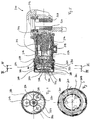
- Fig. 3 and 4 a third embodiment of the invention is shown. This is similar to the second embodiment according to Fig. 2 , In the following, therefore, only the differences from the embodiment according to Fig. 2 describe the same reference numerals as used in the description of the second embodiment, but preceded by the numeral "2" for the same or equivalent components.
- the blocking element 234 is designed with a threaded bolt 230, which is received in a formed in the brake piston 214 inside thread to form a self-loosening thread pairing.
- the brake piston 214 is rotatably guided in the housing 212 via guide pins 270 fixed to the housing 212.
- FIG. 2 also shows the hydraulic fluid supply line 218.
- the blocking element 234 is rotatably mounted in the housing 212 about the piston longitudinal axis A via the bearing arrangement 238.
- the bearing assembly 238 is axially secured via a piston damping element 274 and a locking ring 276.
- the blocking element 234 extends through a wall section 272, in which it is guided in a fluid-tight manner via a sealing element 278.
- a locking disk 262 At his in Fig. 3 left end is attached to the blocking element 234 a locking disk 262 rotatably mounted.
- the locking disc 262 is cup-shaped and has at its radial peripheral portion a locking teeth 264 with recesses 280 into which a locking pin 268 of a solenoid 266 can engage 266 upon activation of the solenoid. Over the circumference of the locking disc 262 a plurality of such recesses 280 is provided.
- the vehicle brake 210 functions analogous to the vehicle brake 110 Fig. 2 , wherein act due to the absence of the planetary gear higher forces on the locking pin 268. It is the same with respect to the Fig. 10 It was also noted that with a very fine pitch of the locking disc 262 with recesses 280 in the description in Fig. 10 addressed setting operations can be minimized and thus the drop in the clamping force of F 1 to F 2 can be kept small in terms of amount.
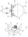
- a fourth embodiment of the vehicle brake according to the invention is shown and generally designated 310. This is similar to the second and third embodiments according to FIG Fig. 2 to 4 , In the following, therefore, only the differences from the embodiments according to Fig. 2 to 4 describe the same reference numerals as in the description of the preceding embodiments are used for the same or equivalent components, but preceded by the numeral "3".
- the blocking element 334 is in turn coupled via a planetary gear 360 with the locking disc 362.
- the planetary gear 360 includes a rotatably mounted on the blocking element sun gear 384, three meshing with this planetary gears 382, which are rotatably mounted on the acting as a planet carrier locking disk 362 via bearing pins 390, and a sun gear 386 rotatably mounted in the housing 312, with which the planet gears 382 mesh.
- FIG. 5 Another feature of the fourth embodiment according to Fig. 5 to 7 is that the locking disc 362 is connected via a coil spring 388 to the housing 312.
- the coil spring 388 is tensioned when the brake piston 314 is displaced to the brake disk, not shown, and thereby builds up a restoring force, the active in his release in the brake piston 314 in this Fig. 5 returns the initial position shown.
- the vehicle brake 312 is like the hydraulic actuated embodiments described above, in particular as in FIG Fig. 3 shown, executed and works accordingly.
- a pawl 468 which is rotatably mounted there in the housing, not shown, via a pin 494, by means of a spring 492 in an in Fig. 8 biased release position not shown.
- the pawl 468 can be against the spring action of the spring 492 in his in Fig. 8 shift shown blocking position in which it is engaged with an internal toothing 464 of the locking disc 462 and blocks it against rotation in the direction of rotation R 1 .
- This direction of rotation R 1 corresponds to a release of the braking effect.
- a rotation in the opposite direction of rotation R 2 that is, a further delivery of the brake, however, is possible.
- Fig. 9 is shown in detail an alternative Verrastungsan extract invention.
- This comprises two pawls 568 1 and 568 2 , which are respectively biased about these associated springs 592 1 and 592 2 in their release position.
- Both pawls 568 1 and 568 2 are actuated via one and the same solenoid 566.
- the pawls 568 1 and 568 2 are arranged and dimensioned in accordance with the pitch of the internal teeth 564 such that only one of the pawls 568 1 and 568 2 is in self-locking engagement with one of the teeth of the internal teeth 564 and the other of the pawls 568 1 and 568 2 then lies between two adjacent teeth of the internal teeth 564.
- a relatively coarse pitch of the internal teeth 564 sufficiently fine locking positions can be provided.
Landscapes
- Engineering & Computer Science (AREA)
- General Engineering & Computer Science (AREA)
- Mechanical Engineering (AREA)
- Braking Arrangements (AREA)
- Braking Systems And Boosters (AREA)
Claims (21)
- Frein automobile (10 ; 110 ; 210 ; 310) comportant- un carter (12 ; 112; 212; 312),- un piston de frein (70 ; 114 ; 214 ; 314) logé dans le carter (12 ; 112 ; 212 ; 312) et portant une garniture de frein (16 ; 126 ; 226 ; 326), et- un dispositif de blocage,le piston de frein (70 ; 114 ; 214 ; 314) pouvant être déplacé dans le carter (12 ; 112 ; 212 ; 312) par l'intermédiaire d'un dispositif d'actionnement et bloqué dans ledit carter (12 ; 112 ; 212 ; 312) par l'intermédiaire du dispositif de blocage,
le dispositif de blocage présentant un ensemble de verrouillage électromécanique qui peut être actionné de manière à bloquer le déplacement du piston de frein (70 ; 114 ; 214 ; 314) dans le carter (12 ; 112 ; 212 ; 312) dans une position d'encliquetage et à libérer le piston de frein (70 ; 114 ; 214 ; 314) pour permettre son déplacement dans le carter dans une position de libération,
et le dispositif d'encliquetage présentant en outre un ensemble d'éléments d'encliquetage (82 ; 168 ; 268 ; 368 ; 468 ; 568) comportant au moins un élément d'encliquetage (82 ; 168 ; 268 ; 368 ; 468 ; 568) déplaçable entre une position d'élément d'encliquetage associée à la position de verrouillage et une position d'élément d'encliquetage associée à la position de libération,
caractérisé en ce qu'au moins un élément d'encliquetage (82 ; 168 ; 268 ; 368 ; 468 ; 568) est précontraint par l'intermédiaire d'un élément ressort (492 ; 592) dans sa position d'élément d'encliquetage associée à la position de libération. - Frein automobile (10 ; 110 ; 210 ; 310) selon la revendication 1,
caractérisé en ce que l'élément d'encliquetage (82 ; 168 ; 268 ; 368 ; 468 ; 568) peut être enclenché par prise autobloquante avec une surface d'attaque (78 ; 164 ; 264 ; 364 ; 464 ; 564) d'un composant d'encliquetage opposé (34 ; 162 ; 262 ; 362 ; 462) couplé en entraînement avec le piston de frein (70 ; 114 ; 214 ; 314). - Frein automobile (10 ; 110 ; 210 ; 310) selon la revendication 2,
caractérisé en ce qu'au moins un élément d'encliquetage (82 ; 168 ; 268 ; 368 ; 468 ; 568) peut être déplacé par l'intermédiaire d'un actionneur électromécanique (80 ; 166 ; 266 ; 366 ; 466 ; 566) entre sa position d'élément d'encliquetage associée à la position de verrouillage et sa position d'élément d'encliquetage associée à la position de libération. - Frein automobile (10 ; 110 ; 210 ; 310) selon l'une des revendications 1 à 3,
caractérisé en ce que deux éléments d'encliquetage (5681, 5682) sont actionnables par l'intermédiaire de l'actionneur électromécanique (566), l'écart entre les éléments d'encliquetage (5681, 5682) et la division du composant d'encliquetage opposé (562) par une pluralité de surfaces d'attaque (564) sont adaptés l'un à l'autre de telle manière que, dans la position de verrouillage, uniquement un des éléments d'encliquetage (5681, 5682) est en prise autobloquante avec une des surfaces d'attaque (564) et l'autre élément d'encliquetage (5681, 5682) vient ce faisant en prise non autobloquante entre deux surfaces d'attaque (564) voisines. - Frein automobile (10 ; 110 ; 210 ; 310) selon l'une des revendications 1 à 4,
caractérisé en ce qu'au moins un élément d'encliquetage (468 ; 568) est constitué par un cliquet d'arrêt (468 ; 568) et en ce que les surfaces d'attaque (464 ; 564) du composant d'encliquetage opposé (462 ; 562) sont conçues comme une denture d'encliquetage. - Frein automobile (10 ; 110 ; 210 ; 310) selon l'une des revendications 1 à 4,
caractérisé en ce qu'au moins un élément d'encliquetage (82 ; 168 ; 268 ; 368) est constitué par un tenon d'encliquetage (82 ; 168 ; 268 ; 368) et en ce que les surfaces d'attaque (78 ; 164 ; 264 ; 364) du composant d'encliquetage opposé (34 ; 162 ; 262 ; 362) sont conçues comme des réservations destinées à recevoir les tenons d'encliquetage. - Frein automobile (10 ; 110 ; 210 ; 310) selon l'une des revendications précédentes,
caractérisé en ce que le piston de frein (70 ; 114 ; 214 ; 314) est couplé avec un élément de blocage (64 ; 34 ; 134 ; 234 ; 334) du dispositif de blocage par l'intermédiaire d'un appariement de filetages à déblocage automatique. - Frein automobile (110) selon la revendication 7,
caractérisé en ce que l'appariement de filetages à déblocage automatique est constitué d'un filetage externe prévu sur un boulon fileté (130) fixé sur le piston de frein (114) et d'un filetage interne prévu sur une douille de logement fixée sur l'élément de blocage (134). - Frein automobile (10 ; 210 ; 310) selon la revendication 7,
caractérisé en ce que l'appariement de filetages à déblocage automatique est constitué d'un filetage interne prévu sur le piston de frein (70 ; 214 ; 314) et d'un filetage externe prévu sur l'élément de blocage (64 ; 234 ; 334). - Frein automobile (10 ; 110 ; 210 ; 310) selon l'une des revendications 7 à 9,
caractérisé en ce que l'élément de blocage (64 ; 134 ; 334) est couplé en entraînement avec le composant d'encliquetage opposé (34 ; 162 ; 362 ; 462) par l'intermédiaire d'un dispositif d'engrenage, plus particulièrement par l'intermédiaire d'un engrenage planétaire (46 ; 148 ; 360). - Frein automobile (310) selon la revendication 10,
caractérisé en ce que l'élément de blocage (334) est couplé fixe en rotation avec une roue solaire (384) de l'engrenage planétaire (360), et en ce qu'en outre le composant d'encliquetage opposé (362) est couplé fixe en rotation avec un porte-satellites de l'engrenage planétaire (360) à l'intérieur du carter (312) et la couronne (386) de l'engrenage planétaire (360) est intégrée dans le carter (312) ou couplée fixe en rotation avec celui-ci. - Frein automobile (10 ; 110) selon la revendication 10,
caractérisé en ce que l'élément de blocage (66 ; 134) est conçu comme un porte-satellites ou couplé fixe en rotation avec un porte-satellites de l'engrenage planétaire, et en ce qu'en outre le composant d'encliquetage opposé (34 ; 162) est couplé fixe en rotation avec une roue solaire (42 ; 160) de l'engrenage planétaire et la couronne (56 ; 152) de l'engrenage planétaire est intégrée dans le carter (12 ; 112) ou couplée fixe en rotation avec celui-ci. - Frein automobile (10 ; 110) selon l'une des revendications 10 à 12,
caractérisé en ce que l'engrenage planétaire (46 ; 148) est conçu comme un engrenage à plusieurs étages. - Frein automobile (110 ; 210 ; 310) selon l'une des revendications précédentes,
caractérisé en ce que le dispositif d'actionnement est de conception hydraulique, le piston de frein (114 ; 214 ; 314) délimitant conjointement avec le carter (112 ; 212 ; 312) une chambre fluidique (16 ; 216 ; 316) laquelle peut être alimentée avec un fluide hydraulique par le biais d'un circuit de fluide hydraulique si bien que le piston de frein (114 ; 214 ; 314) peut être déplacé hydrauliquement à l'intérieur du carter (112 ; 212 ; 312), le long d'un axe longitudinal de piston (A), pour actionner le frein automobile (110 ; 210 ; 310). - Frein automobile (10 ; 110 ; 210 ; 310) selon l'une des revendications 1 à 13,
caractérisé en ce que le dispositif d'actionnement est de conception électromécanique, le piston de frein (14) pouvant être déplacé par commande d'un moteur électrique à l'intérieur du carter (12), le long d'un axe longitudinal de piston (A), pour actionner le frein automobile (10). - Frein automobile (10 ; 210 ; 310) selon l'une des revendications précédentes,
caractérisé en ce que l'élément de blocage (64 ; 234 ; 334) est monté mobile en rotation dans le carter (12 ; 212 ; 312) par l'intermédiaire d'un ensemble palier radial (68 ; 238 ; 338). - Frein automobile (110) selon l'une des revendications précédentes,
caractérisé en ce que l'élément de blocage (134) est monté mobile en rotation dans le carter (112) par l'intermédiaire d'un ensemble palier axial (138). - Frein automobile (10 ; 110 ; 210 ; 310) selon l'une des revendications précédentes,
caractérisé en ce que, en situation de freinage de service, le piston de frein (70 ; 114 ; 214 ; 314) peut être déplacé à l'intérieur du carter (12 ; 112 ; 212 ; 312) par activation du dispositif d'actionnement, et en ce que, en situation de freinage de stationnement, il y a tout d'abord déplacement du piston de frein (70 ; 114 ; 214 ; 314) à l'intérieur du carter (12 ; 112 ; 212 ; 312) par activation du dispositif d'actionnement, puis actionnement du dispositif de blocage et blocage du piston de frein (70 ; 114 ; 214 ; 314) à l'intérieur du carter (12 ; 112 ; 212 ; 312) et finalement désactivation du dispositif d'actionnement. - Frein automobile (10 ; 110 ; 210 ; 310) selon la revendication 18,
caractérisé en ce que, pour débloquer la situation de freinage de stationnement, le dispositif d'actionnement est activé jusqu'à ce que l'élément de blocage (64 ; 234 ; 334 ; 434) libère le piston de frein (70 ; 114 ; 214 ; 314) et le piston de frein (70 ; 114 ; 214 ; 314) est finalement ramené dans sa position de départ sans effet de freinage. - Procédé d'actionnement d'un frein automobile (10 ; 110 ; 210 ; 310) selon l'une des revendications précédentes,
caractérisé en ce que, en situation de freinage de service, le piston de frein (70 ; 114 ; 214 ; 314) peut être déplacé à l'intérieur du carter (12 ; 112 ; 212 ; 312) par activation du dispositif d'actionnement, et en ce que, en situation de freinage de stationnement, il y a tout d'abord déplacement du piston de frein (70 ; 114 ; 214 ; 314) à l'intérieur du carter (12 ; 112 ; 212 ; 312) par activation du dispositif d'actionnement, puis actionnement du dispositif de blocage et blocage du piston de frein (70 ; 114 ; 214 ; 314) à l'intérieur du carter (12 ; 112 ; 212 ; 312) et finalement désactivation du dispositif d'actionnement. - Procédé selon la revendication 20,
caractérisé en ce que, pour débloquer la situation de freinage de stationnement, le dispositif d'actionnement est activé jusqu'à ce que l'élément de blocage (64 ; 234 ; 334 ; 434) libère le piston de frein (70 ; 114 ; 214 ; 314) et le piston de frein (70 ; 114 ; 214 ; 314) est finalement ramené dans sa position de départ sans effet de freinage.
Applications Claiming Priority (2)
| Application Number | Priority Date | Filing Date | Title |
|---|---|---|---|
| DE10320884A DE10320884A1 (de) | 2003-05-09 | 2003-05-09 | Fahrzeugbremse und Verfahren zum Betätigen einer Fahrzeugbremse |
| PCT/EP2004/004770 WO2004099644A1 (fr) | 2003-05-09 | 2004-05-05 | Frein automobile et procede d'actionnement d'un frein automobile |
Publications (2)
| Publication Number | Publication Date |
|---|---|
| EP1623137A1 EP1623137A1 (fr) | 2006-02-08 |
| EP1623137B1 true EP1623137B1 (fr) | 2008-11-19 |
Family
ID=33426722
Family Applications (1)
| Application Number | Title | Priority Date | Filing Date |
|---|---|---|---|
| EP04731149A Expired - Lifetime EP1623137B1 (fr) | 2003-05-09 | 2004-05-05 | Frein automobile et procede d'actionnement d'un frein automobile |
Country Status (5)
| Country | Link |
|---|---|
| US (1) | US7316300B2 (fr) |
| EP (1) | EP1623137B1 (fr) |
| AT (1) | ATE414858T1 (fr) |
| DE (2) | DE10320884A1 (fr) |
| WO (1) | WO2004099644A1 (fr) |
Families Citing this family (17)
| Publication number | Priority date | Publication date | Assignee | Title |
|---|---|---|---|---|
| ES2320700T3 (es) * | 2005-09-27 | 2009-05-27 | Lucas Automotive Gmbh | Freno de vehiculo, especialmente freno con pinza. |
| DE102005055084B4 (de) * | 2005-09-29 | 2017-02-09 | Robert Bosch Gmbh | Kombinierte Betriebs- und Feststellbremseinrichtung |
| DE102005055085B4 (de) * | 2005-09-29 | 2020-09-24 | Robert Bosch Gmbh | Kombinierte Betriebs- und Feststellbremseinrichtung sowie Verfahren zur Durchführung einer Notbremsung |
| DE102006016543A1 (de) * | 2006-04-07 | 2007-10-18 | Lucas Automotive Gmbh | Hydraulisch betätigbare Fahrzeugbremse mit Verriegelung |
| JP4840598B2 (ja) * | 2007-04-27 | 2011-12-21 | 日立オートモティブシステムズ株式会社 | 電動ディスクブレーキ |
| DE102007029927A1 (de) * | 2007-06-28 | 2009-01-02 | Lucas Automotive Gmbh | Scheibenbremse für ein Kraftfahrzeug und Gehäuse hierfür |
| DE102007053278B4 (de) * | 2007-11-08 | 2017-11-09 | Robert Bosch Gmbh | Elektromechanische Feststelleinrichtung für einen Bremskolben einer hydraulisch betätigbaren Radbremse |
| DE102010063320A1 (de) | 2010-12-17 | 2012-06-21 | Continental Teves Ag & Co. Ohg | Elektromechanisch betätigbare Bremse und Verfahren zum Betreiben einer elektromechanisch betätigbaren Bremse |
| US9328809B2 (en) | 2013-04-01 | 2016-05-03 | Goodrich Corporation | Ballscrew assembly having a low friction sleeve |
| JP6414114B2 (ja) * | 2016-03-24 | 2018-10-31 | トヨタ自動車株式会社 | 電動ブレーキキャリパ |
| KR101816397B1 (ko) | 2016-05-04 | 2018-01-08 | 현대자동차주식회사 | 전동식 브레이크 |
| KR101827110B1 (ko) * | 2016-05-10 | 2018-02-07 | 현대자동차주식회사 | 자동 주차 해제가 가능한 전동식 브레이크 |
| CN106184146B (zh) * | 2016-08-22 | 2019-03-15 | 安徽工程大学 | 辅助制动系统 |
| JP7040287B2 (ja) * | 2018-05-25 | 2022-03-23 | トヨタ自動車株式会社 | 車両用ブレーキ装置 |
| KR102682054B1 (ko) * | 2019-03-29 | 2024-07-05 | 에이치엘만도 주식회사 | 전자식 주차 브레이크의 액추에이터 |
| KR102689883B1 (ko) * | 2019-04-03 | 2024-07-30 | 에이치엘만도 주식회사 | 전자식 주차 브레이크의 액추에이터 |
| NL2023353B1 (en) * | 2019-06-20 | 2021-01-28 | Bosch Gmbh Robert | Electric parking brake |
Family Cites Families (11)
| Publication number | Priority date | Publication date | Assignee | Title |
|---|---|---|---|---|
| EP0317303A3 (en) * | 1987-11-20 | 1990-07-04 | Lucas Industries Public Limited Company | Rotary electric drive device |
| US5148894A (en) * | 1990-10-11 | 1992-09-22 | Allied-Signal Inc. | Disk brake/parking brake with threaded piston rod and motor |
| DE19652229A1 (de) * | 1996-12-16 | 1998-06-18 | Bosch Gmbh Robert | Elektromechanisch betätigbare Bremse |
| DE19750420A1 (de) * | 1997-11-14 | 1999-05-20 | Bayerische Motoren Werke Ag | Elektrisch betätigbare Bremse für ein Kraftfahrzeug |
| JP2001524647A (ja) * | 1997-11-21 | 2001-12-04 | コンティネンタル・テーベス・アクチエンゲゼルシヤフト・ウント・コンパニー・オッフェネ・ハンデルスゲゼルシヤフト | 電気機械的に操作可能なディスクブレーキ |
| DE19807328C2 (de) * | 1998-02-20 | 2003-08-28 | Lucas Ind Plc | Elektromechanisch betätigbare Scheibenbremse |
| JP4271852B2 (ja) * | 1998-03-05 | 2009-06-03 | コンティネンタル・テーベス・アクチエンゲゼルシヤフト・ウント・コンパニー・オッフェネ・ハンデルスゲゼルシヤフト | 電気機械的に操作可能なディスクブレーキ用の操作ユニット |
| DE19851670A1 (de) * | 1998-11-10 | 2000-05-11 | Bosch Gmbh Robert | Elektromechanische Radbremsvorrichtung |
| DE19944876A1 (de) * | 1999-09-18 | 2001-03-22 | Continental Teves Ag & Co Ohg | Betätigungseinheit für eine elektromechanisch betätigbare Scheibenbremse |
| DE19945543A1 (de) * | 1999-09-23 | 2001-03-29 | Continental Teves Ag & Co Ohg | Betätigungseinheit für eine elektromechanisch betätigbare Scheibenbremse |
| DE10054471A1 (de) * | 2000-11-03 | 2002-05-16 | Siemens Ag | Elektromechanisch betätigbare Scheibenbremse mit einer Feststellbremsanlage |
-
2003
- 2003-05-09 DE DE10320884A patent/DE10320884A1/de not_active Ceased
-
2004
- 2004-05-05 DE DE502004008488T patent/DE502004008488D1/de not_active Expired - Fee Related
- 2004-05-05 AT AT04731149T patent/ATE414858T1/de not_active IP Right Cessation
- 2004-05-05 EP EP04731149A patent/EP1623137B1/fr not_active Expired - Lifetime
- 2004-05-05 WO PCT/EP2004/004770 patent/WO2004099644A1/fr active Application Filing
-
2005
- 2005-11-09 US US11/270,111 patent/US7316300B2/en not_active Expired - Fee Related
Also Published As
| Publication number | Publication date |
|---|---|
| WO2004099644A1 (fr) | 2004-11-18 |
| US20060054428A1 (en) | 2006-03-16 |
| DE502004008488D1 (de) | 2009-01-02 |
| DE10320884A1 (de) | 2004-12-16 |
| EP1623137A1 (fr) | 2006-02-08 |
| US7316300B2 (en) | 2008-01-08 |
| ATE414858T1 (de) | 2008-12-15 |
Similar Documents
| Publication | Publication Date | Title |
|---|---|---|
| EP1623137B1 (fr) | Frein automobile et procede d'actionnement d'un frein automobile | |
| EP1554504B1 (fr) | Frein hydraulique de vehicule | |
| EP3086987B1 (fr) | Frein de véhicule à actionnement hydraulique et électromagnétique avec blocage automatique sélectif | |
| DE3815225C2 (fr) | ||
| EP1169581A1 (fr) | Frein a disque a garniture partielle comportant une unite d'actionnement electromecanique | |
| DE102012217275A1 (de) | Scheibenbremsvorrichtung | |
| EP2195218A1 (fr) | Vis d'entraînement à billes pour un frein de véhicule à moteur et frein de véhicule à moteur | |
| DE102009019793A1 (de) | Kombinierte Fahrzeugbremse mit elektromechanisch betätigbarer Feststellbremse | |
| DE102013224922A1 (de) | Elektromechanisch betätigbare Trommelbremse | |
| EP3068668A2 (fr) | Frein de véhicule à actionnement combiné hydraulique et électromécanique avec blocage automatique optionnel | |
| EP2005021A1 (fr) | Frein de vehicule hydraulique avec verrouillage | |
| DE102016201177A1 (de) | Parksperrenvorrichtung für ein Fahrzeuggetriebe | |
| DE102014221090A1 (de) | Planetenwälzgetriebe und Aktor mit diesem | |
| EP0762005A1 (fr) | Moteur de frein à transmission hydraulique | |
| DE19648581A1 (de) | Scheibenbremse mit Feststellbremsfunktion | |
| DE19741865C1 (de) | Bremsaktuator | |
| EP0807561A2 (fr) | Dispositif anti-retour pour véhicules automobiles | |
| DE10329694A1 (de) | Hydraulische Fahrzeugbremse | |
| WO1999054637A1 (fr) | Actionneur pour le systeme de freinage d'un vehicule automobile | |
| DE19922333A1 (de) | Scheibenbremse mit Feststellbremsfunktion | |
| DE102020127413A1 (de) | Parksperre für ein Getriebe sowie Getriebe und Antriebsstrang | |
| DE102006001543A1 (de) | Hydraulische Fahrzeugbremse mit Feststellbremsvorrichtung | |
| EP1360429A1 (fr) | Frein a disque | |
| EP0237840A2 (fr) | Dispositif de commande pour embrayage à friction pour le verrouillage d'un différentiel de véhicule | |
| EP0416412A1 (fr) | Frein, spécialement frein à disque |
Legal Events
| Date | Code | Title | Description |
|---|---|---|---|
| PUAI | Public reference made under article 153(3) epc to a published international application that has entered the european phase |
Free format text: ORIGINAL CODE: 0009012 |
|
| 17P | Request for examination filed |
Effective date: 20051027 |
|
| AK | Designated contracting states |
Kind code of ref document: A1 Designated state(s): AT BE BG CH CY CZ DE DK EE ES FI FR GB GR HU IE IT LI LU MC NL PL PT RO SE SI SK TR |
|
| DAX | Request for extension of the european patent (deleted) | ||
| GRAP | Despatch of communication of intention to grant a patent |
Free format text: ORIGINAL CODE: EPIDOSNIGR1 |
|
| GRAS | Grant fee paid |
Free format text: ORIGINAL CODE: EPIDOSNIGR3 |
|
| GRAA | (expected) grant |
Free format text: ORIGINAL CODE: 0009210 |
|
| AK | Designated contracting states |
Kind code of ref document: B1 Designated state(s): AT BE BG CH CY CZ DE DK EE ES FI FR GB GR HU IE IT LI LU MC NL PL PT RO SE SI SK TR |
|
| REG | Reference to a national code |
Ref country code: GB Ref legal event code: FG4D Free format text: NOT ENGLISH |
|
| REG | Reference to a national code |
Ref country code: CH Ref legal event code: EP |
|
| REG | Reference to a national code |
Ref country code: IE Ref legal event code: FG4D Free format text: LANGUAGE OF EP DOCUMENT: GERMAN |
|
| REF | Corresponds to: |
Ref document number: 502004008488 Country of ref document: DE Date of ref document: 20090102 Kind code of ref document: P |
|
| PG25 | Lapsed in a contracting state [announced via postgrant information from national office to epo] |
Ref country code: ES Free format text: LAPSE BECAUSE OF FAILURE TO SUBMIT A TRANSLATION OF THE DESCRIPTION OR TO PAY THE FEE WITHIN THE PRESCRIBED TIME-LIMIT Effective date: 20090301 |
|
| NLV1 | Nl: lapsed or annulled due to failure to fulfill the requirements of art. 29p and 29m of the patents act | ||
| PG25 | Lapsed in a contracting state [announced via postgrant information from national office to epo] |
Ref country code: FI Free format text: LAPSE BECAUSE OF FAILURE TO SUBMIT A TRANSLATION OF THE DESCRIPTION OR TO PAY THE FEE WITHIN THE PRESCRIBED TIME-LIMIT Effective date: 20081119 Ref country code: PL Free format text: LAPSE BECAUSE OF FAILURE TO SUBMIT A TRANSLATION OF THE DESCRIPTION OR TO PAY THE FEE WITHIN THE PRESCRIBED TIME-LIMIT Effective date: 20081119 Ref country code: SI Free format text: LAPSE BECAUSE OF FAILURE TO SUBMIT A TRANSLATION OF THE DESCRIPTION OR TO PAY THE FEE WITHIN THE PRESCRIBED TIME-LIMIT Effective date: 20081119 Ref country code: NL Free format text: LAPSE BECAUSE OF FAILURE TO SUBMIT A TRANSLATION OF THE DESCRIPTION OR TO PAY THE FEE WITHIN THE PRESCRIBED TIME-LIMIT Effective date: 20081119 |
|
| REG | Reference to a national code |
Ref country code: IE Ref legal event code: FD4D |
|
| PG25 | Lapsed in a contracting state [announced via postgrant information from national office to epo] |
Ref country code: RO Free format text: LAPSE BECAUSE OF FAILURE TO SUBMIT A TRANSLATION OF THE DESCRIPTION OR TO PAY THE FEE WITHIN THE PRESCRIBED TIME-LIMIT Effective date: 20081119 Ref country code: BG Free format text: LAPSE BECAUSE OF FAILURE TO SUBMIT A TRANSLATION OF THE DESCRIPTION OR TO PAY THE FEE WITHIN THE PRESCRIBED TIME-LIMIT Effective date: 20090219 Ref country code: EE Free format text: LAPSE BECAUSE OF FAILURE TO SUBMIT A TRANSLATION OF THE DESCRIPTION OR TO PAY THE FEE WITHIN THE PRESCRIBED TIME-LIMIT Effective date: 20081119 Ref country code: DK Free format text: LAPSE BECAUSE OF FAILURE TO SUBMIT A TRANSLATION OF THE DESCRIPTION OR TO PAY THE FEE WITHIN THE PRESCRIBED TIME-LIMIT Effective date: 20081119 Ref country code: IE Free format text: LAPSE BECAUSE OF FAILURE TO SUBMIT A TRANSLATION OF THE DESCRIPTION OR TO PAY THE FEE WITHIN THE PRESCRIBED TIME-LIMIT Effective date: 20081119 |
|
| PG25 | Lapsed in a contracting state [announced via postgrant information from national office to epo] |
Ref country code: SE Free format text: LAPSE BECAUSE OF FAILURE TO SUBMIT A TRANSLATION OF THE DESCRIPTION OR TO PAY THE FEE WITHIN THE PRESCRIBED TIME-LIMIT Effective date: 20090219 Ref country code: PT Free format text: LAPSE BECAUSE OF FAILURE TO SUBMIT A TRANSLATION OF THE DESCRIPTION OR TO PAY THE FEE WITHIN THE PRESCRIBED TIME-LIMIT Effective date: 20090420 Ref country code: CZ Free format text: LAPSE BECAUSE OF FAILURE TO SUBMIT A TRANSLATION OF THE DESCRIPTION OR TO PAY THE FEE WITHIN THE PRESCRIBED TIME-LIMIT Effective date: 20081119 |
|
| PLBE | No opposition filed within time limit |
Free format text: ORIGINAL CODE: 0009261 |
|
| STAA | Information on the status of an ep patent application or granted ep patent |
Free format text: STATUS: NO OPPOSITION FILED WITHIN TIME LIMIT |
|
| PG25 | Lapsed in a contracting state [announced via postgrant information from national office to epo] |
Ref country code: SK Free format text: LAPSE BECAUSE OF FAILURE TO SUBMIT A TRANSLATION OF THE DESCRIPTION OR TO PAY THE FEE WITHIN THE PRESCRIBED TIME-LIMIT Effective date: 20081119 |
|
| 26N | No opposition filed |
Effective date: 20090820 |
|
| BERE | Be: lapsed |
Owner name: LUCAS AUTOMOTIVE G.M.B.H. Effective date: 20090531 |
|
| PG25 | Lapsed in a contracting state [announced via postgrant information from national office to epo] |
Ref country code: MC Free format text: LAPSE BECAUSE OF NON-PAYMENT OF DUE FEES Effective date: 20090531 |
|
| REG | Reference to a national code |
Ref country code: CH Ref legal event code: PL |
|
| GBPC | Gb: european patent ceased through non-payment of renewal fee |
Effective date: 20090505 |
|
| PG25 | Lapsed in a contracting state [announced via postgrant information from national office to epo] |
Ref country code: LI Free format text: LAPSE BECAUSE OF NON-PAYMENT OF DUE FEES Effective date: 20090531 Ref country code: CH Free format text: LAPSE BECAUSE OF NON-PAYMENT OF DUE FEES Effective date: 20090531 |
|
| REG | Reference to a national code |
Ref country code: FR Ref legal event code: ST Effective date: 20100129 |
|
| PG25 | Lapsed in a contracting state [announced via postgrant information from national office to epo] |
Ref country code: FR Free format text: LAPSE BECAUSE OF NON-PAYMENT OF DUE FEES Effective date: 20090602 |
|
| PG25 | Lapsed in a contracting state [announced via postgrant information from national office to epo] |
Ref country code: GB Free format text: LAPSE BECAUSE OF NON-PAYMENT OF DUE FEES Effective date: 20090505 |
|
| PG25 | Lapsed in a contracting state [announced via postgrant information from national office to epo] |
Ref country code: DE Free format text: LAPSE BECAUSE OF NON-PAYMENT OF DUE FEES Effective date: 20091201 Ref country code: BE Free format text: LAPSE BECAUSE OF NON-PAYMENT OF DUE FEES Effective date: 20090531 |
|
| PG25 | Lapsed in a contracting state [announced via postgrant information from national office to epo] |
Ref country code: AT Free format text: LAPSE BECAUSE OF NON-PAYMENT OF DUE FEES Effective date: 20090505 |
|
| PG25 | Lapsed in a contracting state [announced via postgrant information from national office to epo] |
Ref country code: GR Free format text: LAPSE BECAUSE OF FAILURE TO SUBMIT A TRANSLATION OF THE DESCRIPTION OR TO PAY THE FEE WITHIN THE PRESCRIBED TIME-LIMIT Effective date: 20090220 |
|
| PG25 | Lapsed in a contracting state [announced via postgrant information from national office to epo] |
Ref country code: IT Free format text: LAPSE BECAUSE OF FAILURE TO SUBMIT A TRANSLATION OF THE DESCRIPTION OR TO PAY THE FEE WITHIN THE PRESCRIBED TIME-LIMIT Effective date: 20081119 |
|
| PG25 | Lapsed in a contracting state [announced via postgrant information from national office to epo] |
Ref country code: LU Free format text: LAPSE BECAUSE OF NON-PAYMENT OF DUE FEES Effective date: 20090505 |
|
| PG25 | Lapsed in a contracting state [announced via postgrant information from national office to epo] |
Ref country code: HU Free format text: LAPSE BECAUSE OF FAILURE TO SUBMIT A TRANSLATION OF THE DESCRIPTION OR TO PAY THE FEE WITHIN THE PRESCRIBED TIME-LIMIT Effective date: 20090520 |
|
| PG25 | Lapsed in a contracting state [announced via postgrant information from national office to epo] |
Ref country code: TR Free format text: LAPSE BECAUSE OF FAILURE TO SUBMIT A TRANSLATION OF THE DESCRIPTION OR TO PAY THE FEE WITHIN THE PRESCRIBED TIME-LIMIT Effective date: 20081119 |
|
| PG25 | Lapsed in a contracting state [announced via postgrant information from national office to epo] |
Ref country code: CY Free format text: LAPSE BECAUSE OF FAILURE TO SUBMIT A TRANSLATION OF THE DESCRIPTION OR TO PAY THE FEE WITHIN THE PRESCRIBED TIME-LIMIT Effective date: 20081119 |