EP1621134A1 - Sonde ultrasonore et dispositif ultrasonographique - Google Patents
Sonde ultrasonore et dispositif ultrasonographique Download PDFInfo
- Publication number
- EP1621134A1 EP1621134A1 EP04721998A EP04721998A EP1621134A1 EP 1621134 A1 EP1621134 A1 EP 1621134A1 EP 04721998 A EP04721998 A EP 04721998A EP 04721998 A EP04721998 A EP 04721998A EP 1621134 A1 EP1621134 A1 EP 1621134A1
- Authority
- EP
- European Patent Office
- Prior art keywords
- ultrasonic
- encoder
- transducer
- ultrasonic transducer
- count value
- Prior art date
- Legal status (The legal status is an assumption and is not a legal conclusion. Google has not performed a legal analysis and makes no representation as to the accuracy of the status listed.)
- Withdrawn
Links
Images


Classifications
-
- A—HUMAN NECESSITIES
- A61—MEDICAL OR VETERINARY SCIENCE; HYGIENE
- A61B—DIAGNOSIS; SURGERY; IDENTIFICATION
- A61B8/00—Diagnosis using ultrasonic, sonic or infrasonic waves
- A61B8/48—Diagnostic techniques
- A61B8/483—Diagnostic techniques involving the acquisition of a 3D volume of data
-
- A—HUMAN NECESSITIES
- A61—MEDICAL OR VETERINARY SCIENCE; HYGIENE
- A61B—DIAGNOSIS; SURGERY; IDENTIFICATION
- A61B8/00—Diagnosis using ultrasonic, sonic or infrasonic waves
-
- A—HUMAN NECESSITIES
- A61—MEDICAL OR VETERINARY SCIENCE; HYGIENE
- A61B—DIAGNOSIS; SURGERY; IDENTIFICATION
- A61B8/00—Diagnosis using ultrasonic, sonic or infrasonic waves
- A61B8/44—Constructional features of the ultrasonic, sonic or infrasonic diagnostic device
- A61B8/4444—Constructional features of the ultrasonic, sonic or infrasonic diagnostic device related to the probe
- A61B8/4461—Features of the scanning mechanism, e.g. for moving the transducer within the housing of the probe
Definitions
- the present invention relates to an ultrasonic probe that is directed to obtaining three-dimensional echo data by receiving an ultrasonic echo that is obtained by the reflection of an ultrasonic beam transmitted with respect to a tissue in a living body or the like, and relates to an ultrasonic diagnostic apparatus in which the ultrasonic probe is used.
- an ultrasonic probe for obtaining three-dimensional data which is used in an ultrasonic diagnostic apparatus intended to display the condition of a tissue in a living body three-dimensionally
- an ultrasonic probe including an ultrasonic transducer for scanning an ultrasonic beam which is configured so as to swing mechanically the ultrasonic transducer to perform swing scanning in a direction that crosses the beam scanning direction
- ultrasonic beam scanning hereinafter, called principal cross-section scanning
- swing scanning By performing ultrasonic beam scanning (hereinafter, called principal cross-section scanning) and swing scanning at the same time, echo data corresponding to a line of intersection of both scanning planes that move momentarily, that is, three-dimensional echo data, can be obtained.
- the obtained three-dimensional echo data is subjected to three-dimensional image processing, thereby displaying an image within a plane as if it has a depth, displaying its required cross section or the like.
- the ultrasonic transducer is composed of a plurality of element arrays
- beam scanning is performed electronically, and thus a directional component of the echo data within a beam scanning plane can be obtained by a scanning position, an arrangement of the transducer elements composing the ultrasonic transducer and a beam direction.
- the ultrasonic probe is configured so that an angle of the swing scanned plane being scanned mechanically is obtained by counting pulses from a rotary encoder that is provided to a rotation axis of a motor for swinging the ultrasonic transducer.
- a three-dimensional image formed by an ultrasonic diagnostic apparatus has been used for observing a condition of a tissue in a living body, penetrating while monitoring the three-dimensional image and a guideline, or measuring a distance and an angle of an organ, a tumor, a fetus or the like, thus enhancing the usability thereof.
- an ultrasonic diagnostic apparatus In the light of the requirements for such medical purposes, it is necessary for an ultrasonic diagnostic apparatus to form a three-dimensional image with higher precision than conventional ultrasonic diagnostic apparatuses, that is, to form an image in a spatially correct position.
- a swing scanning angle that is necessary for forming a three-dimensional image is obtained only by counting pulses output from a rotary encoder that is provided on a rotation axis of a swinging motor in an ultrasonic probe.
- an actual swing scanning angle of an ultrasonic transducer with respect to each count value that is obtained by counting pulses from a rotary encoder varies according to the individual ultrasonic probe, due to a variation in installation precision between a rotation axis of a motor and a rotary encoder, wobbling of a rotation transmission mechanism, a variation in installation precision between an ultrasonic transducer and the rotation transmission mechanism, a variation of the rotary encoder itself or the like.
- an ultrasonic probe that corrects, based on encoder information, a scanning error (flexure or elongation of a rotation transmission mechanism with respect to a speed) occurring according to a change in amount of a scanning load of the ultrasonic probe is known (see, for example, JP 2(1990)-57242 A).
- this kind of ultrasonic probe requires to have a power supply, a switch and the like for the correction and needs a discontinuance of the operation thereof, which leads to an increase in the size of an ultrasonic diagnostic apparatus and causes a problem in workability and cost.
- the actual swing scanning angle of the ultrasonic transducer with respect to each count value that is obtained by counting the pulses from the rotary encoder may differ between its forward path and its return path, which is caused by wobbling of the rotation transmission mechanism or the like.
- the swing scanning angle with respect to each count value varies according to the individual ultrasonic probe, and differs between the forward path of the swinging and the return path thereof. Therefore, according to the ultrasonic probe to be used, the formed three-dimensional image is distorted, is displaced, flickers due to the reciprocation of its swinging or the like, which may result in problems such as penetrating in a direction deviated from the direction expected by the operator, and a large error in a result of the measurement of a distance and an angle.
- the present invention intends to solve the above-mentioned conventional problems so as to provide an excellent ultrasonic diagnostic apparatus that can form a three-dimensional image in a more spatially-correct position regardless of an ultrasonic probe to be used, without leading to deterioration of the productivity of the treatment, and to provide an ultrasonic probe that is suitable for being applied in such ultrasonic diagnostic apparatus.
- the ultrasonic probe includes: an ultrasonic transducer that scans an ultrasonic beam; a transducer-swinging motor that allows the ultrasonic transducer to perform swing scanning in a direction crossing a scanning direction of the ultrasonic beam; a rotary encoder that generates a pulse according to a rotational position of the transducer-swinging motor; and an encoder correction ROM that stores an actual swing scanning angle of the ultrasonic transducer with respect to each count value obtained by counting pulses from the rotary encoder, and outputs the stored actual swing scanning angle of the ultrasonic transducer to outside.
- the actual swing scanning angle of the ultrasonic transducer with respect to each count value that is obtained by counting the pulses from the rotary encoder can be stored in an encoder correction ROM in advance, and the actual swing scanning angle of the ultrasonic transducer with respect to each count value, which varies according to the individual ultrasonic probe, depending on a method of mechanical scanning, can be known.
- the encoder correction ROM preferably stores swing directional angles that are different between a forward path of swing scanning and a return path of the swing scanning.
- the actual swing scanning angles of the ultrasonic transducer on the forward path of the swinging and on the return path thereof with respect to the count value that is obtained by counting the pulses from the rotary encoder can be stored in the encoder correction ROM in advance, and the actual swing scanning angle of the ultrasonic transducer with respect to each count value, which varies according to the individual ultrasonic probe, depending on a method of mechanical scanning, and differs between the forward path of the swinging and the return path thereof, can be obtained.
- a first ultrasonic diagnostic apparatus includes : the ultrasonic probe according to the present invention; a transmitting/receiving means that excites vibrators of the ultrasonic transducer and receives an ultrasonic echo reflected by a subject; an encoder counter that counts pulses from the rotary encoder; a main controlling means that reads out, from the encoder correction ROM in the ultrasonic probe, the actual swing scanning angle of the ultrasonic transducer with respect to each of the counter value; a motor controlling means that performs driving control on the transducer-swinging motor according to the count value from the encoder counter; a three-dimensional image processing means that forms a three-dimensional image based on ultrasonic echo data obtained by the transmitting/receiving means, the count value from the encoder counter and the actual swing scanning angle of the ultrasonic transducer with respect to each of the count value that is provided by the main controlling means; and an image display means that displays
- a three-dimensional image can be formed while being corrected, based on the actual swing scanning angle of the ultrasonic transducer with respect to each count value, which varies according to the individual ultrasonic probe.
- a second ultrasonic diagnostic apparatus includes: the ultrasonic probe according to the present invention; a transmitting/receiving means that excites vibrators of the ultrasonic transducer and receives an ultrasonic echo reflected by a subject; an encoder counter that counts pulses from the rotary encoder; a main controlling means that reads out, from the encoder correction ROM in the ultrasonic probe, the actual swing scanning angle of the ultrasonic transducer with respect to each of the count value; a motor controlling means that performs driving control on the transducer-swinging motor according to the count value from the encoder counter and the actual swing scanning angle of the ultrasonic transducer with respect to each of the count value that is provided by the main controlling means; a three-dimensional image processing means that forms a three-dimensional image based on ultrasonic echo data obtained by the transmitting/receiving means; and an image display means that displays the three-dimensional image.
- the swinging can be controlled while a swing scanning direction is corrected based on the actual swing scanning angle of the ultrasonic transducer with respect to each count value, which varies according to the individual ultrasonic probe.
- an excellent ultrasonic diagnostic apparatus that can form a three-dimensional image in a more spatially-correct position regardless of the ultrasonic probe to be used, without leading to deterioration of the productivity of the treatment, can be obtained.
- a low-cost and small-sized ultrasonic probe can be realized by using a flash ROM or an E-square ROM that is available at low cost and small in size as the encoder correction ROM.
- correction data with nonvolatility is stored in the encoder correction ROM in advance, time for obtaining data that is necessary for the correction is not required additionally.
- deviation of the angle between the forward path of the swinging and the return path thereof can be corrected flexibly according to the swing scanning angle (that is, an output value of the encoder) of the ultrasonic transducer.
- FIG. 1 is a block diagram showing an example of a configuration of the ultrasonic diagnostic apparatus according to Embodiment 1 of the present invention.
- the ultrasonic diagnostic apparatus shown in FIG. 1 will be applied also in the respective embodiments described below.
- the ultrasonic diagnostic apparatus includes an ultrasonic transducer 1 with a plurality of transducer elements 2 arranged in array, the transducer element 2 transmitting an ultrasonic beam into a living body and converting an ultrasonic echo from a tissue in the living body into an electric signal.
- Each of the transducer elements 2 is excited by a transmission pulse provided by a transmitting/receiving means 8.
- the transmitting/receiving means 8 is controlled to provide the transmission pulses with different phases to a part of or all of the transducer elements 2 arranged in the ultrasonic transducer 1, so that the transmission pulse is focused at a predetermined depth in the living body, that is, a transmission beam is formed.
- the ultrasonic beam transmitted to the living body as mentioned above returns as an echo from the respective tissues in the living body momentarily.
- the transmitting/receiving means 8 performs an adding operation with respect to the ultrasonic echoes that are converted into the electric signals by the transducer elements 2 of the ultrasonic transducer 1 so that each reception beam is formed in the predetermined direction, after providing different delay times with respect to reception signals from transducer elements 2.
- the above-described transmission beam and this reception beam form one acoustic scanning line by a transmission/reception, that is, the transmitting/receiving means 8 generates and outputs ultrasonic echo data along this acoustic scanning line.
- the transmission/reception is performed so as to form acoustic scanning lines in different directions by switching a group of the transducer elements to be used for the transmission/reception sequentially, or changing directions of the transmission/reception beams. As a result, one principal cross-section scanning plane is formed.
- the ultrasonic diagnostic apparatus includes a transducer-swinging motor 5 that allows the ultrasonic transducer 1 to perform swing scanning in a direction crossing the above-mentioned principal cross-section scanning plane, and the transducer-swinging motor 5 is subjected to driving control by a motor controlling means 6.
- the transmitting/receiving means 8 can generate the ultrasonic echo data that corresponds to a line of intersection of the principal cross-section scanning plane and a swing scanning plane.
- both of the scanning planes are not scanned independently, but are scanned so as to obtain ultrasonic echo data of a certain three-dimensional part in an organic body equally. That is, the principal cross-section scanning and the swing scanning are performed so that the number of the principal cross-section scanning planes per one swing scanning is always constant, and angles between the respective principal cross-section scanning planes are substantially the same.
- the motor controlling means 6 needs to control the swinging while constantly monitoring a swing scanning angle of the ultrasonic transducer 1 that is connected to the transducer-swinging motor 5.
- the ultrasonic diagnostic apparatus includes a rotary encoder 4 that is provided on a rotation axis of the transducer-swinging motor 5.
- a preferred example of the rotary encoder 4 is shown in FIG. 2.
- This rotary encoder 4 includes a Z-pulse rotor 21 provided on a rotation axis 20 so that one pulse (hereinafter, called a Z-pulse) is output at a certain angle of the rotation axis 20.
- the Z-pulse rotor 21 is magnetized so as to generate one Z-pulse per one rotation, and a Z-pulse sensor 23 detects the magnetized part of the Z-pulse rotor 21 and outputs a Z-pulse.
- the rotary encoder 4 includes an A-pulse rotor 22 and an A-pulse sensor 24 so as to generate several hundreds of pulses (hereinafter, called A-pulses) fixedly per one rotation of the rotation axis 20.
- the magnetic encoder was exemplified in the above description, but an optical encoder or a mechanical encoder may be applied in the configuration of the present invention.
- An encoder counter 7 is reset by the Z-pulses from the rotary encoder 4, and is counted up or down by the A-pulses. And, a count value thereof corresponds to an angle of the rotation axis of the transducer-swinging motor 5, that is, the swing scanning angle of the ultrasonic transducer 1.
- the motor controlling means 6 can obtain the current swing scanning angle of the ultrasonic transducer 1 according to the count value provided by the encoder counter 7, as mentioned above, and thus can control the transducer-swinging motor 5 so as to move the ultrasonic transducer 1 to a subsequent predetermined swing scanning angle.
- the ultrasonic echo data on the certain three-dimensional part in the living body which is obtained by performing the principal cross-section scanning and the swing scanning in synchronization as mentioned above, is transmitted from the transmitting/receiving means 8 to a three-dimensional image processing means 11.
- a three-dimensional image processing is performed with respect to the obtained ultrasonic echo data so that a configuration of the certain three-dimensional part in the living body may be displayed as if it has a depth, or the configuration viewed from a point of view in any directions may be displayed on an image display means 12 having a flat or slowly curved display surface.
- the three-dimensional image processing means 11 obtains a directional component of an angle of the scanning direction on the principal cross-section scanning plane, by an arrangement of the transducer elements 2 composing the ultrasonic transducer 1 and directions of the transmission/reception beams. Whereas, the three-dimensional image processing means 11 obtains a directional component of the angle of the scanning direction on the swing scanning plane by the count value provided by the encoder counter 7.
- the actual swing scanning angle of the ultrasonic transducer 1 with respect to each count value that is obtained by counting pulses from the rotary encoder 4 varies according to the ultrasonic diagnostic apparatus, due to an accumulation of respective variations of installation precision between the rotation axis of the transducer-swinging motor 5 and the rotary encoder 4, precision of a rotation transmission mechanism 3 with respect to the rotation axis of the transducer-swinging motor 5 and the ultrasonic transducer 1, installation precision between the ultrasonic transducer 1 and the rotation transmission mechanism 3, precision of an angle of the rotary encoder 4 for generating the Z-pulse, a linearity of the number of A-pulses with respect to the angle of the rotation axis and the like.
- the encoder correction ROM 9 is provided for storing the actual swing scanning angle of the ultrasonic transducer 1 with respect to each count value that is to be obtained from the encoder counter 7, or a numerical value corresponding to the swing scanning angle is stored.
- the encoder correction ROM 9 holds the stored value after an electric current in the ultrasonic diagnostic apparatus is OFF, and does not lose the value still after an electric current is ON again.
- the value stored in the encoder correction ROM 9 is read by the main controlling means 10, and the value or a value corrected by an appropriate value subsequently is transmitted via the main controlling means 10 to the three-dimensional image processing means 11, the motor controlling means 6 or both of the three-dimensional image processing means 11 and the motor controlling means 6.
- the ultrasonic transducer 1 or the ultrasonic transducer 1 with its peripheral portions unified therewith can be separated from the main portion of the ultrasonic diagnostic apparatus, and is mobile, which is called an ultrasonic probe. That is, it is not necessary that a certain ultrasonic probe is always applied to the main portion of the same ultrasonic diagnostic apparatus.
- the ultrasonic transducer 1, the rotary encoder 4, the transducer-swinging motor 5 and the encoder correction ROM 9 compose the ultrasonic probe 13, which can be separated from the main portion of the ultrasonic diagnostic apparatus. This is because, since substantially all portions that can cause the occurrence of the variations of the swing scanning angle with respect to the count value of the rotary encoder 4 are included, the encoder correction ROM 9 can correct the accumulation of the variations together, even in the case where the ultrasonic probe 13 is applied to a main portion of different ultrasonic diagnostic apparatus.
- Embodiment 2 of the present invention will be described with reference to FIG. 1 as well as Embodiment 1.
- swing scanning mostly is performed as reciprocating scanning. This method is intended for forming a three-dimensional image at more real time. Also in this case, even when count values provided by the encoder counter 7 on a forward path of the swing scanning and on its return path are equal, real swing scanning angles thereof are often different, which is a problem caused by a mechanical scanning method, in addition to the above-mentioned problem.
- the above-mentioned phenomenon leads to a problem where positions of the three-dimensional image formed on the forward path and on the return path are different, that is, the three-dimensional image flickers, or a problem where distortions of the three-dimensional images formed on the forward path and on the return path are different.
- the encoder correction ROM 9 can store different correction data between the forward path of the swing scanning and the return path thereof, a correction data for the forward path can be used on the forward path of the swinging, and a correction data for the return path can be used on the return path thereof, thereby solving the above-described problem.
- Embodiment 3 of the present invention an ultrasonic diagnostic apparatus that can form a more precise three-dimensional image by the ultrasonic probe 13 including the above-mentioned encoder correction ROM 9 and the like will be described with reference to FIGs. 2 to 6.
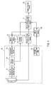
- a correction value 31 as shown in FIG. 3 is stored in advance.
- a straight line 30 shows a case where the swing scanning angle of the ultrasonic transducer 1 with respect to the count value of the encoder counter 7 is ideal, and where the encoder counter 7 is an up-counter, using the rotary encoder 4 that generates N number of A-pulses during one rotation of the rotation axis of the transducer-swinging motor 5 and a Z-pulse when the angle of the rotation axis is 0°.
- the present embodiment exemplifies the case where the angle of the rotation axis coincides with an angle of the ultrasonic transducer 1, but the case where a rotation speed transmission ratio of the rotation transmission mechanism 3 is not 1:1 also can be applied.
- the correction value 31 in FIG. 3 shows the actual swing scanning angle of the ultrasonic transducer 1 with respect to a count value provided by the encoder counter 7, and shows that, for example, when the count value is “ j ", the actual angle for this ultrasonic probe is “a'” in spite of the ideal angle being “ a ". Similarly, the actual angle is " b"' with respect to the count value of " k “, while the ideal angle is “ b ".
- the correction value 31 is read out by the main controlling means 10, and is transmitted to the three-dimensional image processing means 11.
- the three-dimensional image processing means 11 obtains the encoder correction value for the applied ultrasonic probe 13 in advance, and can form an image of the principal cross-section scanning plane at the actual swing scanning angle, while correcting the encoder count value with respect to the obtained ultrasonic echo data, thereby forming a more precise three-dimensional image of a tissue in a living body.
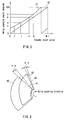
- FIGs. 5 and 6 an example of performing the swing scanning in reciprocation is shown in FIGs. 5 and 6.
- a forward-path correction values 51 having a direction of increasing the encoder count value and a return-path correction values 52 having a direction of decreasing the encoder count value are stored in advance.
- the both correction values are on the same track as shown by a straight line 50.
- the encoder correction values 51 and 52 in FIG. 5 show that, for example, when the encoder count value is " k ", the actual swing scanning angle of the ultrasonic transducer on the forward path is " c' " and that on the return path is " c" ".
- the forward-path correction value 51 and the return-path correction value 52 are transmitted to the three-dimensional image processing means 11 by the main controlling means 10 in advance, when the count value provided by the encoder counter 7 is " k ", unless the correction value is provided, only a principal cross-section scanning plane 60 can be formed at an angle of " c " in the swing scanning direction on both of the forward path and the return path, as shown in the example of FIG. 6.
- the three-dimensional image processing means 11 obtains the actual angle of "c"' on the forward path from the main controlling means 10 in advance, and thus forms an image of a principal-cross-section scanning plane 63 on the forward path in a direction deviated by the difference of " c'-c ", and forms an image of a principal cross-section scanning plane 61 on the return path in a direction deviated by the difference of "c-c" ".
- the three-dimensional image processing means 11 obtains the encoder correction values on both of the forward path and the return path of the swing scanning of the applied ultrasonic probe 13 in advance, and can form the image of the principal cross-section scanning plane at the actual swing scanning angle, while correcting the encoder count values on the forward path and the return path with respect to the obtained ultrasonic echo data to be different values, thereby forming a more precise three-dimensional image of a tissue in a living body.
- Embodiment 4 of the present invention an ultrasonic diagnostic apparatus that can form a more precise three-dimensional image by the motor controlling means 6, using the encoder correction ROM 9, will be described.
- the three-dimensional image processing means 11 corrects the angle of the three-dimensional image to be formed, based on the encoder correction value, and the similar effect also can be obtained by the motor controlling means 6.
- the correction value 31 in FIG. 3 is the actual swing scanning angle of the ultrasonic transducer 1 with respect to the count value provided by the encoder counter 7. This correction value is transmitted to the motor controlling means 6 by the main controlling means 10 in advance (shown as the arrow with the broken line in FIG. 1).
- the motor controlling means 6 of the ultrasonic diagnostic apparatus obtains the encoder correction value in advance, and thus may control the transducer-swinging motor 5 so that the encoder count value may be " j'" with respect to the desired value of " a ".
- the three-dimensional image processing means 11 forms an image in a direction at the provided angle, because the obtained ultrasonic echo data is already corresponding to the principal cross-section scanning plane at the desired swing scanning angle.
- a three-dimensional image of a tissue in a living body can be formed more precisely.
- the present invention can provide an excellent ultrasonic diagnostic apparatus that can correct a variation in installation precision between the rotation axis of the motor and the rotary encoder, precision of the rotation transmission mechanism, a variation in installation precision between the ultrasonic transducer and the rotation transmission mechanism and a variation of the rotary encoder itself, which may vary according to the individual ultrasonic probe, and thus can form a three-dimensional image in a more spatially-correct position regardless of the ultrasonic probe to be used.
- the main portion of the ultrasonic diagnostic apparatus can obtain the correction data and correct the swing scanning angle of the ultrasonic transducer, an excellent ultrasonic diagnostic apparatus can be provided, which does not require the operator to perform any correction processes even when the applied probe is changed, and displays a three-dimensional image with high precision.
- the encoder correction ROM can store swing directional angles that are different between the forward path of the swing scanning and the return path thereof, and thus can correct the actual swing scanning angles of the ultrasonic transducer with respect to the encoder count values, which are different between the forward path and the return path due to wobbling of the rotation transmission mechanism or the like, thereby providing an excellent ultrasonic diagnostic apparatus that can suppress a problem of flicker or distortion of the image depending on the swing reciprocation, regardless of the ultrasonic probe to be used.
- a low-cost and small-sized ultrasonic probe can be realized by using a flash ROM or an E-square ROM that is available at low cost and small in size as the encoder correction ROM.
- correction data with nonvolatility is stored in the encoder correction ROM in advance, time for obtaining the data that is necessary for the correction is not required additionally
- deviation of the angle between the forward path of the swinging and the return path thereof can be corrected flexibly, according to the swing scanning angle (that is, the output value of the encoder) of the ultrasonic transducer.
Landscapes
- Life Sciences & Earth Sciences (AREA)
- Health & Medical Sciences (AREA)
- Biomedical Technology (AREA)
- Biophysics (AREA)
- Nuclear Medicine, Radiotherapy & Molecular Imaging (AREA)
- Pathology (AREA)
- Radiology & Medical Imaging (AREA)
- Engineering & Computer Science (AREA)
- Physics & Mathematics (AREA)
- Heart & Thoracic Surgery (AREA)
- Medical Informatics (AREA)
- Molecular Biology (AREA)
- Surgery (AREA)
- Animal Behavior & Ethology (AREA)
- General Health & Medical Sciences (AREA)
- Public Health (AREA)
- Veterinary Medicine (AREA)
- Ultra Sonic Daignosis Equipment (AREA)
- Investigating Or Analyzing Materials By The Use Of Ultrasonic Waves (AREA)
Applications Claiming Priority (2)
| Application Number | Priority Date | Filing Date | Title |
|---|---|---|---|
| JP2003078833 | 2003-03-20 | ||
| PCT/JP2004/003745 WO2004082482A1 (fr) | 2003-03-20 | 2004-03-19 | Sonde ultrasonore et dispositif ultrasonographique |
Publications (1)
| Publication Number | Publication Date |
|---|---|
| EP1621134A1 true EP1621134A1 (fr) | 2006-02-01 |
Family
ID=33027987
Family Applications (1)
| Application Number | Title | Priority Date | Filing Date |
|---|---|---|---|
| EP04721998A Withdrawn EP1621134A1 (fr) | 2003-03-20 | 2004-03-19 | Sonde ultrasonore et dispositif ultrasonographique |
Country Status (5)
| Country | Link |
|---|---|
| US (1) | US20060241424A1 (fr) |
| EP (1) | EP1621134A1 (fr) |
| JP (1) | JPWO2004082482A1 (fr) |
| CN (1) | CN1761428A (fr) |
| WO (1) | WO2004082482A1 (fr) |
Families Citing this family (16)
| Publication number | Priority date | Publication date | Assignee | Title |
|---|---|---|---|---|
| US7457654B2 (en) * | 2003-10-27 | 2008-11-25 | Siemens Medical Solutions Usa, Inc. | Artifact reduction for volume acquisition |
| JP4596974B2 (ja) * | 2005-05-17 | 2010-12-15 | パナソニック株式会社 | 超音波診断装置 |
| JP4740647B2 (ja) * | 2005-05-18 | 2011-08-03 | パナソニック株式会社 | 超音波探触子 |
| JP2007006983A (ja) * | 2005-06-28 | 2007-01-18 | Toshiba Corp | 超音波診断装置 |
| JP4668110B2 (ja) | 2006-03-30 | 2011-04-13 | 日本電波工業株式会社 | 超音波探触子 |
| CN101067618B (zh) * | 2007-06-08 | 2010-05-19 | 华中科技大学 | 一种用于检测非金属介质的多通道超声波采集装置 |
| JP5231822B2 (ja) * | 2008-01-23 | 2013-07-10 | 株式会社東芝 | 超音波診断装置、及び超音波診断装置の制御プログラム |
| CN101480347B (zh) * | 2009-01-20 | 2011-01-05 | 深圳市蓝韵实业有限公司 | 一种四维超声探头电机控制系统 |
| US9161736B2 (en) * | 2009-09-10 | 2015-10-20 | Hitachi Medical Corporation | Ultrasonic diagnostic apparatus and elasticity image display method |
| KR102333542B1 (ko) * | 2014-11-13 | 2021-12-01 | 삼성메디슨 주식회사 | 초음파 프로브 및 그 제어 방법 |
| KR102591372B1 (ko) * | 2015-10-27 | 2023-10-20 | 삼성메디슨 주식회사 | 초음파 프로브 |
| JP6945334B2 (ja) * | 2016-05-26 | 2021-10-06 | キヤノンメディカルシステムズ株式会社 | 超音波診断装置及び医用画像処理装置 |
| CN106950285B (zh) * | 2017-04-19 | 2023-10-03 | 中国科学院声学研究所 | 一种手推式探头装置及调整方法 |
| CN107928709B (zh) * | 2017-07-03 | 2023-06-06 | 深圳英美达医疗技术有限公司 | 一种内窥成像系统及其控制方法 |
| KR20200112389A (ko) * | 2019-03-22 | 2020-10-05 | 삼성메디슨 주식회사 | 초음파 영상 장치 및 그 제어 방법 |
| KR102301418B1 (ko) * | 2021-01-07 | 2021-09-10 | 부경대학교 산학협력단 | 고속 스캔 광음향 영상 입력장치 및 그 제어방법 |
Family Cites Families (20)
| Publication number | Priority date | Publication date | Assignee | Title |
|---|---|---|---|---|
| GB2063474B (en) * | 1979-10-24 | 1984-06-06 | Olympus Optical Co | Coeliac cavity ultrasonic diagnosis apparatus |
| US4429262A (en) * | 1980-09-12 | 1984-01-31 | Technicare Corporation | Three phase motor oscillatory servo control |
| US4544868A (en) * | 1984-07-20 | 1985-10-01 | General Motors Corporation | Brushless DC motor controller |
| JPH0710256B2 (ja) * | 1985-11-07 | 1995-02-08 | 株式会社東芝 | 超音波走査パルス発生装置 |
| US4868476A (en) * | 1987-10-30 | 1989-09-19 | Hewlett-Packard Company | Transducer with integral memory |
| US4932414A (en) * | 1987-11-02 | 1990-06-12 | Cornell Research Foundation, Inc. | System of therapeutic ultrasound and real-time ultrasonic scanning |
| JPH01227743A (ja) | 1988-03-07 | 1989-09-11 | Fuji Electric Co Ltd | 超音波画像の補正方式 |
| JPH0749038B2 (ja) | 1988-08-23 | 1995-05-31 | 松下電器産業株式会社 | メカニカルセクタ型超音波診断装置 |
| US5159931A (en) * | 1988-11-25 | 1992-11-03 | Riccardo Pini | Apparatus for obtaining a three-dimensional reconstruction of anatomic structures through the acquisition of echographic images |
| EP0448610B1 (fr) * | 1988-12-15 | 1994-06-29 | Papst Licensing GmbH | Procede et dispositif pour la commande de convertisseurs electro-mecaniques |
| KR900015432A (ko) * | 1989-02-06 | 1990-10-27 | 미다 가쓰시게 | 이동체의 속도 제어 장치 |
| JPH02124553U (fr) * | 1989-03-27 | 1990-10-15 | ||
| JPH0738851B2 (ja) | 1989-12-14 | 1995-05-01 | アロカ株式会社 | 三次元データ取り込み用超音波探触子 |
| DE69027284T2 (de) * | 1989-12-14 | 1996-12-05 | Aloka Co Ltd | Dreidimensionaler Ultraschallabtaster |
| US5251631A (en) * | 1990-11-07 | 1993-10-12 | Kabushiki Kaisha Toshiba | Ultrasonic imaging apparatus |
| JPH0531109A (ja) * | 1990-11-07 | 1993-02-09 | Toshiba Corp | 超音波イメージング装置 |
| JP3460351B2 (ja) * | 1994-02-08 | 2003-10-27 | セイコーエプソン株式会社 | 位置検出装置及び位置検出方法 |
| US5699806A (en) * | 1996-10-01 | 1997-12-23 | Hewlett-Packard Company | Ultrasound system with nonuniform rotation corrector |
| JP4648537B2 (ja) * | 2000-11-21 | 2011-03-09 | パナソニック株式会社 | 超音波診断装置 |
| US6686585B2 (en) * | 2001-09-19 | 2004-02-03 | Microe Systems Corporation | Position encoder with scale calibration |
-
2004
- 2004-03-19 WO PCT/JP2004/003745 patent/WO2004082482A1/fr not_active Application Discontinuation
- 2004-03-19 US US10/550,118 patent/US20060241424A1/en not_active Abandoned
- 2004-03-19 CN CNA2004800075784A patent/CN1761428A/zh active Pending
- 2004-03-19 EP EP04721998A patent/EP1621134A1/fr not_active Withdrawn
- 2004-03-19 JP JP2005503758A patent/JPWO2004082482A1/ja active Pending
Non-Patent Citations (1)
| Title |
|---|
| See references of WO2004082482A1 * |
Also Published As
| Publication number | Publication date |
|---|---|
| JPWO2004082482A1 (ja) | 2006-06-15 |
| WO2004082482A1 (fr) | 2004-09-30 |
| CN1761428A (zh) | 2006-04-19 |
| US20060241424A1 (en) | 2006-10-26 |
Similar Documents
| Publication | Publication Date | Title |
|---|---|---|
| EP1621134A1 (fr) | Sonde ultrasonore et dispositif ultrasonographique | |
| EP1354557B1 (fr) | Dispositif de diagnostique à ultrasons | |
| US7090642B2 (en) | Ultrasonic transmitting and receiving apparatus and ultrasonic transmitting and receiving method | |
| US5078145A (en) | Ultrasonic diagnostic device | |
| US20070232924A1 (en) | Ultrasonic probe and ultrasonic diagnosing apparatus | |
| EP2679167B1 (fr) | Échographe | |
| US6638220B2 (en) | Ultrasonic imaging method and ultrasonic imaging apparatus | |
| EP1834587B1 (fr) | Appareil de diagnostic ultrasonique et procédé pour l'affichage d'une image ultrason | |
| US5186176A (en) | Ultrasonic diagnosis apparatus | |
| US4880009A (en) | Ultrasonic imaging apparatus | |
| JPH0655212B2 (ja) | 超音波診断装置 | |
| JP5060175B2 (ja) | 超音波画像診断装置 | |
| EP0022966A2 (fr) | Appareil de diagnostic ultrasonique | |
| JP6387713B2 (ja) | 超音波診断装置及び超音波探触子 | |
| US20070272021A1 (en) | Ultrasonographic equipment | |
| JPH0254096B2 (fr) | ||
| JP2007007343A (ja) | 超音波診断装置 | |
| US20240050071A1 (en) | Ultrasound diagnostic apparatus and method for controlling ultrasound diagnostic apparatus | |
| JP2004255017A (ja) | 超音波プローブおよび超音波診断装置 | |
| JP4656892B2 (ja) | 超音波診断装置 | |
| JP5627436B2 (ja) | 超音波診断装置 | |
| KR840001818B1 (ko) | 초음파 진단장치 | |
| JP2006334279A (ja) | 超音波診断装置 | |
| JP2004275265A (ja) | 超音波診断装置 | |
| JP2001104304A (ja) | 超音波診断装置 |
Legal Events
| Date | Code | Title | Description |
|---|---|---|---|
| PUAI | Public reference made under article 153(3) epc to a published international application that has entered the european phase |
Free format text: ORIGINAL CODE: 0009012 |
|
| 17P | Request for examination filed |
Effective date: 20051010 |
|
| AK | Designated contracting states |
Kind code of ref document: A1 Designated state(s): DE FR GB |
|
| RIN1 | Information on inventor provided before grant (corrected) |
Inventor name: AKIYAMA, HISASHI Inventor name: FUJII, KIYOSHI |
|
| DAX | Request for extension of the european patent (deleted) | ||
| RBV | Designated contracting states (corrected) |
Designated state(s): DE FR GB |
|
| STAA | Information on the status of an ep patent application or granted ep patent |
Free format text: STATUS: THE APPLICATION HAS BEEN WITHDRAWN |
|
| 18W | Application withdrawn |
Effective date: 20060622 |