EP1620908B1 - Solid oxide fuel cell anodes and electrodes for other electrochemical devices - Google Patents
Solid oxide fuel cell anodes and electrodes for other electrochemical devices Download PDFInfo
- Publication number
- EP1620908B1 EP1620908B1 EP04760402A EP04760402A EP1620908B1 EP 1620908 B1 EP1620908 B1 EP 1620908B1 EP 04760402 A EP04760402 A EP 04760402A EP 04760402 A EP04760402 A EP 04760402A EP 1620908 B1 EP1620908 B1 EP 1620908B1
- Authority
- EP
- European Patent Office
- Prior art keywords
- anode
- layer
- fuel cell
- anode layer
- electrolyte
- Prior art date
- Legal status (The legal status is an assumption and is not a legal conclusion. Google has not performed a legal analysis and makes no representation as to the accuracy of the status listed.)
- Expired - Lifetime
Links
- 239000000446 fuel Substances 0.000 title claims description 71
- 239000007787 solid Substances 0.000 title claims description 27
- 239000003792 electrolyte Substances 0.000 claims abstract description 52
- HBMJWWWQQXIZIP-UHFFFAOYSA-N silicon carbide Chemical compound [Si+]#[C-] HBMJWWWQQXIZIP-UHFFFAOYSA-N 0.000 claims abstract description 37
- 229910010271 silicon carbide Inorganic materials 0.000 claims abstract description 37
- 239000007789 gas Substances 0.000 claims description 18
- 229910001233 yttria-stabilized zirconia Inorganic materials 0.000 claims description 14
- VYPSYNLAJGMNEJ-UHFFFAOYSA-N Silicium dioxide Chemical compound O=[Si]=O VYPSYNLAJGMNEJ-UHFFFAOYSA-N 0.000 claims description 12
- PXHVJJICTQNCMI-UHFFFAOYSA-N Nickel Chemical compound [Ni] PXHVJJICTQNCMI-UHFFFAOYSA-N 0.000 claims description 9
- 239000000919 ceramic Substances 0.000 claims description 9
- 150000003377 silicon compounds Chemical class 0.000 claims description 9
- 150000002500 ions Chemical class 0.000 claims description 8
- 230000001590 oxidative effect Effects 0.000 claims description 7
- 239000007800 oxidant agent Substances 0.000 claims description 5
- 229910052814 silicon oxide Inorganic materials 0.000 claims description 5
- 239000002737 fuel gas Substances 0.000 claims description 3
- 229910052759 nickel Inorganic materials 0.000 claims description 3
- 238000000034 method Methods 0.000 abstract description 16
- 239000000463 material Substances 0.000 description 25
- 238000005245 sintering Methods 0.000 description 12
- 239000000203 mixture Substances 0.000 description 9
- 239000002245 particle Substances 0.000 description 9
- 239000000758 substrate Substances 0.000 description 9
- 238000004519 manufacturing process Methods 0.000 description 8
- 238000006243 chemical reaction Methods 0.000 description 6
- 238000013461 design Methods 0.000 description 6
- 238000011161 development Methods 0.000 description 6
- 230000018109 developmental process Effects 0.000 description 6
- 239000000835 fiber Substances 0.000 description 6
- 230000009467 reduction Effects 0.000 description 6
- 239000010405 anode material Substances 0.000 description 5
- 238000010276 construction Methods 0.000 description 5
- 238000010586 diagram Methods 0.000 description 5
- 239000001301 oxygen Substances 0.000 description 5
- 229910052760 oxygen Inorganic materials 0.000 description 5
- QVGXLLKOCUKJST-UHFFFAOYSA-N atomic oxygen Chemical compound [O] QVGXLLKOCUKJST-UHFFFAOYSA-N 0.000 description 4
- 230000015572 biosynthetic process Effects 0.000 description 4
- 239000011195 cermet Substances 0.000 description 4
- 238000005516 engineering process Methods 0.000 description 4
- 239000007784 solid electrolyte Substances 0.000 description 4
- 238000005382 thermal cycling Methods 0.000 description 4
- ZWEHNKRNPOVVGH-UHFFFAOYSA-N 2-Butanone Chemical compound CCC(C)=O ZWEHNKRNPOVVGH-UHFFFAOYSA-N 0.000 description 3
- 230000008901 benefit Effects 0.000 description 3
- 229910052681 coesite Inorganic materials 0.000 description 3
- 229910052906 cristobalite Inorganic materials 0.000 description 3
- 238000009792 diffusion process Methods 0.000 description 3
- 230000000694 effects Effects 0.000 description 3
- 239000004615 ingredient Substances 0.000 description 3
- 239000012528 membrane Substances 0.000 description 3
- VNWKTOKETHGBQD-UHFFFAOYSA-N methane Chemical compound C VNWKTOKETHGBQD-UHFFFAOYSA-N 0.000 description 3
- RVTZCBVAJQQJTK-UHFFFAOYSA-N oxygen(2-);zirconium(4+) Chemical compound [O-2].[O-2].[Zr+4] RVTZCBVAJQQJTK-UHFFFAOYSA-N 0.000 description 3
- 239000000843 powder Substances 0.000 description 3
- 238000010248 power generation Methods 0.000 description 3
- 238000000926 separation method Methods 0.000 description 3
- 239000000377 silicon dioxide Substances 0.000 description 3
- 229910052682 stishovite Inorganic materials 0.000 description 3
- 239000000126 substance Substances 0.000 description 3
- 229910052905 tridymite Inorganic materials 0.000 description 3
- 229910001928 zirconium oxide Inorganic materials 0.000 description 3
- LFQSCWFLJHTTHZ-UHFFFAOYSA-N Ethanol Chemical compound CCO LFQSCWFLJHTTHZ-UHFFFAOYSA-N 0.000 description 2
- OAKJQQAXSVQMHS-UHFFFAOYSA-N Hydrazine Chemical compound NN OAKJQQAXSVQMHS-UHFFFAOYSA-N 0.000 description 2
- MCMNRKCIXSYSNV-UHFFFAOYSA-N Zirconium dioxide Chemical compound O=[Zr]=O MCMNRKCIXSYSNV-UHFFFAOYSA-N 0.000 description 2
- 230000002411 adverse Effects 0.000 description 2
- 239000011230 binding agent Substances 0.000 description 2
- 239000006229 carbon black Substances 0.000 description 2
- 230000015556 catabolic process Effects 0.000 description 2
- 239000002131 composite material Substances 0.000 description 2
- 238000007796 conventional method Methods 0.000 description 2
- 238000001816 cooling Methods 0.000 description 2
- 238000005336 cracking Methods 0.000 description 2
- 239000002270 dispersing agent Substances 0.000 description 2
- 230000005611 electricity Effects 0.000 description 2
- 239000007772 electrode material Substances 0.000 description 2
- 239000002001 electrolyte material Substances 0.000 description 2
- 239000005350 fused silica glass Substances 0.000 description 2
- 239000012210 heat-resistant fiber Substances 0.000 description 2
- 239000001257 hydrogen Substances 0.000 description 2
- 229910052739 hydrogen Inorganic materials 0.000 description 2
- 125000004435 hydrogen atom Chemical class [H]* 0.000 description 2
- 239000010416 ion conductor Substances 0.000 description 2
- 229910052746 lanthanum Inorganic materials 0.000 description 2
- FZLIPJUXYLNCLC-UHFFFAOYSA-N lanthanum atom Chemical compound [La] FZLIPJUXYLNCLC-UHFFFAOYSA-N 0.000 description 2
- 230000007246 mechanism Effects 0.000 description 2
- 229910052751 metal Inorganic materials 0.000 description 2
- 239000002184 metal Substances 0.000 description 2
- 229910000480 nickel oxide Inorganic materials 0.000 description 2
- GNRSAWUEBMWBQH-UHFFFAOYSA-N oxonickel Chemical compound [Ni]=O GNRSAWUEBMWBQH-UHFFFAOYSA-N 0.000 description 2
- -1 oxygen ions Chemical class 0.000 description 2
- 239000004014 plasticizer Substances 0.000 description 2
- 230000008569 process Effects 0.000 description 2
- 238000001878 scanning electron micrograph Methods 0.000 description 2
- 238000007650 screen-printing Methods 0.000 description 2
- 239000002904 solvent Substances 0.000 description 2
- IATRAKWUXMZMIY-UHFFFAOYSA-N strontium oxide Chemical compound [O-2].[Sr+2] IATRAKWUXMZMIY-UHFFFAOYSA-N 0.000 description 2
- 238000010345 tape casting Methods 0.000 description 2
- MEOVPKDOYAIVHZ-UHFFFAOYSA-N 2-chloro-1-(1-methylpyrrol-2-yl)ethanol Chemical compound CN1C=CC=C1C(O)CCl MEOVPKDOYAIVHZ-UHFFFAOYSA-N 0.000 description 1
- ZOXJGFHDIHLPTG-UHFFFAOYSA-N Boron Chemical compound [B] ZOXJGFHDIHLPTG-UHFFFAOYSA-N 0.000 description 1
- OKTJSMMVPCPJKN-UHFFFAOYSA-N Carbon Chemical compound [C] OKTJSMMVPCPJKN-UHFFFAOYSA-N 0.000 description 1
- 229920000049 Carbon (fiber) Polymers 0.000 description 1
- UGFAIRIUMAVXCW-UHFFFAOYSA-N Carbon monoxide Chemical compound [O+]#[C-] UGFAIRIUMAVXCW-UHFFFAOYSA-N 0.000 description 1
- MYMOFIZGZYHOMD-UHFFFAOYSA-N Dioxygen Chemical compound O=O MYMOFIZGZYHOMD-UHFFFAOYSA-N 0.000 description 1
- ZOKXTWBITQBERF-UHFFFAOYSA-N Molybdenum Chemical compound [Mo] ZOKXTWBITQBERF-UHFFFAOYSA-N 0.000 description 1
- RTAQQCXQSZGOHL-UHFFFAOYSA-N Titanium Chemical compound [Ti] RTAQQCXQSZGOHL-UHFFFAOYSA-N 0.000 description 1
- BQENXCOZCUHKRE-UHFFFAOYSA-N [La+3].[La+3].[O-][Mn]([O-])=O.[O-][Mn]([O-])=O.[O-][Mn]([O-])=O Chemical class [La+3].[La+3].[O-][Mn]([O-])=O.[O-][Mn]([O-])=O.[O-][Mn]([O-])=O BQENXCOZCUHKRE-UHFFFAOYSA-N 0.000 description 1
- 230000004913 activation Effects 0.000 description 1
- 230000004075 alteration Effects 0.000 description 1
- 230000003466 anti-cipated effect Effects 0.000 description 1
- 238000013459 approach Methods 0.000 description 1
- 238000000429 assembly Methods 0.000 description 1
- 230000000712 assembly Effects 0.000 description 1
- 238000005452 bending Methods 0.000 description 1
- 229910052796 boron Inorganic materials 0.000 description 1
- 125000000484 butyl group Chemical group [H]C([*])([H])C([H])([H])C([H])([H])C([H])([H])[H] 0.000 description 1
- BRPQOXSCLDDYGP-UHFFFAOYSA-N calcium oxide Chemical compound [O-2].[Ca+2] BRPQOXSCLDDYGP-UHFFFAOYSA-N 0.000 description 1
- ODINCKMPIJJUCX-UHFFFAOYSA-N calcium oxide Inorganic materials [Ca]=O ODINCKMPIJJUCX-UHFFFAOYSA-N 0.000 description 1
- 239000000292 calcium oxide Substances 0.000 description 1
- 238000003490 calendering Methods 0.000 description 1
- 239000004917 carbon fiber Substances 0.000 description 1
- 229910002091 carbon monoxide Inorganic materials 0.000 description 1
- 229910021525 ceramic electrolyte Inorganic materials 0.000 description 1
- 229910000428 cobalt oxide Inorganic materials 0.000 description 1
- IVMYJDGYRUAWML-UHFFFAOYSA-N cobalt(ii) oxide Chemical compound [Co]=O IVMYJDGYRUAWML-UHFFFAOYSA-N 0.000 description 1
- 150000001875 compounds Chemical class 0.000 description 1
- 239000004020 conductor Substances 0.000 description 1
- 239000011162 core material Substances 0.000 description 1
- 238000000354 decomposition reaction Methods 0.000 description 1
- 238000006731 degradation reaction Methods 0.000 description 1
- 238000003618 dip coating Methods 0.000 description 1
- 238000001035 drying Methods 0.000 description 1
- 238000003487 electrochemical reaction Methods 0.000 description 1
- 238000002474 experimental method Methods 0.000 description 1
- 238000001914 filtration Methods 0.000 description 1
- 239000012530 fluid Substances 0.000 description 1
- 239000002803 fossil fuel Substances 0.000 description 1
- 230000006870 function Effects 0.000 description 1
- 229910002804 graphite Inorganic materials 0.000 description 1
- 239000010439 graphite Substances 0.000 description 1
- 230000002209 hydrophobic effect Effects 0.000 description 1
- 238000010030 laminating Methods 0.000 description 1
- 238000003475 lamination Methods 0.000 description 1
- 239000011244 liquid electrolyte Substances 0.000 description 1
- 238000003801 milling Methods 0.000 description 1
- 238000012986 modification Methods 0.000 description 1
- 230000004048 modification Effects 0.000 description 1
- 229910003465 moissanite Inorganic materials 0.000 description 1
- 229910052750 molybdenum Inorganic materials 0.000 description 1
- 239000011733 molybdenum Substances 0.000 description 1
- 229910052758 niobium Inorganic materials 0.000 description 1
- 239000010955 niobium Substances 0.000 description 1
- GUCVJGMIXFAOAE-UHFFFAOYSA-N niobium atom Chemical compound [Nb] GUCVJGMIXFAOAE-UHFFFAOYSA-N 0.000 description 1
- 239000004745 nonwoven fabric Substances 0.000 description 1
- 238000010422 painting Methods 0.000 description 1
- 230000000704 physical effect Effects 0.000 description 1
- 230000010287 polarization Effects 0.000 description 1
- 229920002037 poly(vinyl butyral) polymer Polymers 0.000 description 1
- 229920001343 polytetrafluoroethylene Polymers 0.000 description 1
- 239000004810 polytetrafluoroethylene Substances 0.000 description 1
- 238000012545 processing Methods 0.000 description 1
- 230000001737 promoting effect Effects 0.000 description 1
- 239000005871 repellent Substances 0.000 description 1
- 238000004062 sedimentation Methods 0.000 description 1
- 229910052710 silicon Inorganic materials 0.000 description 1
- 239000010703 silicon Substances 0.000 description 1
- LIVNPJMFVYWSIS-UHFFFAOYSA-N silicon monoxide Chemical class [Si-]#[O+] LIVNPJMFVYWSIS-UHFFFAOYSA-N 0.000 description 1
- 238000005549 size reduction Methods 0.000 description 1
- 239000002002 slurry Substances 0.000 description 1
- 238000005507 spraying Methods 0.000 description 1
- 239000010935 stainless steel Substances 0.000 description 1
- 229910001220 stainless steel Inorganic materials 0.000 description 1
- 229910052715 tantalum Inorganic materials 0.000 description 1
- GUVRBAGPIYLISA-UHFFFAOYSA-N tantalum atom Chemical compound [Ta] GUVRBAGPIYLISA-UHFFFAOYSA-N 0.000 description 1
- 238000007669 thermal treatment Methods 0.000 description 1
- 238000002411 thermogravimetry Methods 0.000 description 1
- 239000010936 titanium Substances 0.000 description 1
- 229910052719 titanium Inorganic materials 0.000 description 1
- WFKWXMTUELFFGS-UHFFFAOYSA-N tungsten Chemical compound [W] WFKWXMTUELFFGS-UHFFFAOYSA-N 0.000 description 1
- 229910052721 tungsten Inorganic materials 0.000 description 1
- 239000010937 tungsten Substances 0.000 description 1
- 229920002554 vinyl polymer Polymers 0.000 description 1
- XLYOFNOQVPJJNP-UHFFFAOYSA-N water Substances O XLYOFNOQVPJJNP-UHFFFAOYSA-N 0.000 description 1
- 229910000859 α-Fe Inorganic materials 0.000 description 1
Images


Classifications
-
- H—ELECTRICITY
- H01—ELECTRIC ELEMENTS
- H01M—PROCESSES OR MEANS, e.g. BATTERIES, FOR THE DIRECT CONVERSION OF CHEMICAL ENERGY INTO ELECTRICAL ENERGY
- H01M4/00—Electrodes
- H01M4/86—Inert electrodes with catalytic activity, e.g. for fuel cells
- H01M4/8605—Porous electrodes
- H01M4/8621—Porous electrodes containing only metallic or ceramic material, e.g. made by sintering or sputtering
-
- H—ELECTRICITY
- H01—ELECTRIC ELEMENTS
- H01M—PROCESSES OR MEANS, e.g. BATTERIES, FOR THE DIRECT CONVERSION OF CHEMICAL ENERGY INTO ELECTRICAL ENERGY
- H01M4/00—Electrodes
- H01M4/86—Inert electrodes with catalytic activity, e.g. for fuel cells
- H01M4/88—Processes of manufacture
- H01M4/8878—Treatment steps after deposition of the catalytic active composition or after shaping of the electrode being free-standing body
- H01M4/8882—Heat treatment, e.g. drying, baking
- H01M4/8885—Sintering or firing
-
- H—ELECTRICITY
- H01—ELECTRIC ELEMENTS
- H01M—PROCESSES OR MEANS, e.g. BATTERIES, FOR THE DIRECT CONVERSION OF CHEMICAL ENERGY INTO ELECTRICAL ENERGY
- H01M4/00—Electrodes
- H01M4/86—Inert electrodes with catalytic activity, e.g. for fuel cells
- H01M4/90—Selection of catalytic material
- H01M4/9041—Metals or alloys
- H01M4/905—Metals or alloys specially used in fuel cell operating at high temperature, e.g. SOFC
- H01M4/9066—Metals or alloys specially used in fuel cell operating at high temperature, e.g. SOFC of metal-ceramic composites or mixtures, e.g. cermets
-
- H—ELECTRICITY
- H01—ELECTRIC ELEMENTS
- H01M—PROCESSES OR MEANS, e.g. BATTERIES, FOR THE DIRECT CONVERSION OF CHEMICAL ENERGY INTO ELECTRICAL ENERGY
- H01M8/00—Fuel cells; Manufacture thereof
- H01M8/10—Fuel cells with solid electrolytes
- H01M8/12—Fuel cells with solid electrolytes operating at high temperature, e.g. with stabilised ZrO2 electrolyte
- H01M8/1213—Fuel cells with solid electrolytes operating at high temperature, e.g. with stabilised ZrO2 electrolyte characterised by the electrode/electrolyte combination or the supporting material
- H01M8/1226—Fuel cells with solid electrolytes operating at high temperature, e.g. with stabilised ZrO2 electrolyte characterised by the electrode/electrolyte combination or the supporting material characterised by the supporting layer
-
- H—ELECTRICITY
- H01—ELECTRIC ELEMENTS
- H01M—PROCESSES OR MEANS, e.g. BATTERIES, FOR THE DIRECT CONVERSION OF CHEMICAL ENERGY INTO ELECTRICAL ENERGY
- H01M8/00—Fuel cells; Manufacture thereof
- H01M8/10—Fuel cells with solid electrolytes
- H01M8/12—Fuel cells with solid electrolytes operating at high temperature, e.g. with stabilised ZrO2 electrolyte
- H01M8/124—Fuel cells with solid electrolytes operating at high temperature, e.g. with stabilised ZrO2 electrolyte characterised by the process of manufacturing or by the material of the electrolyte
- H01M8/1246—Fuel cells with solid electrolytes operating at high temperature, e.g. with stabilised ZrO2 electrolyte characterised by the process of manufacturing or by the material of the electrolyte the electrolyte consisting of oxides
- H01M8/1253—Fuel cells with solid electrolytes operating at high temperature, e.g. with stabilised ZrO2 electrolyte characterised by the process of manufacturing or by the material of the electrolyte the electrolyte consisting of oxides the electrolyte containing zirconium oxide
-
- Y—GENERAL TAGGING OF NEW TECHNOLOGICAL DEVELOPMENTS; GENERAL TAGGING OF CROSS-SECTIONAL TECHNOLOGIES SPANNING OVER SEVERAL SECTIONS OF THE IPC; TECHNICAL SUBJECTS COVERED BY FORMER USPC CROSS-REFERENCE ART COLLECTIONS [XRACs] AND DIGESTS
- Y02—TECHNOLOGIES OR APPLICATIONS FOR MITIGATION OR ADAPTATION AGAINST CLIMATE CHANGE
- Y02E—REDUCTION OF GREENHOUSE GAS [GHG] EMISSIONS, RELATED TO ENERGY GENERATION, TRANSMISSION OR DISTRIBUTION
- Y02E60/00—Enabling technologies; Technologies with a potential or indirect contribution to GHG emissions mitigation
- Y02E60/30—Hydrogen technology
- Y02E60/50—Fuel cells
-
- Y—GENERAL TAGGING OF NEW TECHNOLOGICAL DEVELOPMENTS; GENERAL TAGGING OF CROSS-SECTIONAL TECHNOLOGIES SPANNING OVER SEVERAL SECTIONS OF THE IPC; TECHNICAL SUBJECTS COVERED BY FORMER USPC CROSS-REFERENCE ART COLLECTIONS [XRACs] AND DIGESTS
- Y02—TECHNOLOGIES OR APPLICATIONS FOR MITIGATION OR ADAPTATION AGAINST CLIMATE CHANGE
- Y02P—CLIMATE CHANGE MITIGATION TECHNOLOGIES IN THE PRODUCTION OR PROCESSING OF GOODS
- Y02P70/00—Climate change mitigation technologies in the production process for final industrial or consumer products
- Y02P70/50—Manufacturing or production processes characterised by the final manufactured product
Definitions
- the present invention relates generally to the field of electrochemical devices, and more particularly but not exclusively to anode supported electrochemical cells and methods of fabrication.
- Materials and devices in accordance with the invention find advantageous use in solid oxide electrolyte electrochemical devices such as, for example, solid oxide fuel cells, electrolyzers, electrochemical sensors and the like.
- electrochemical devices based on solid oxide electrolytes have received, and continue to receive, significant attention.
- solid state oxygen separation devices have received significant attention for the separation of pure oxygen from air.
- electrochemical fuel cell devices are believed to have significant potential for use as power sources.
- Fuel cell devices are known and used for the direct production of electricity from standard fuel materials including fossil fuels, hydrogen, and the like by converting chemical energy of a fuel into electrical energy.
- Fuel cells typically include a porous fuel electrode (also referred to as the "anode”), a porous air electrode (also referred to as the "cathode”), and a solid or liquid electrolyte therebetween.
- gaseous fuel materials are contacted, typically as a continuous stream, with the anode of the fuel cell system, while an oxidizing gas, for example air or oxygen, is allowed to pass in contact with the cathode of the system.
- an oxidizing gas for example air or oxygen
- Electrical energy is produced by electrochemical combination of the fuel with the oxidant. Because the fuel cells convert the chemical energy of the fuel directly into electricity without the intermediate thermal and mechanical energy step, their efficiency can be substantially higher than that of conventional methods of power generation.
- Solid oxide fuel cells employing a dense ceramic electrolyte are currently considered as one of the most attractive technologies for electric power generation.
- a solid electrolyte separates the porous metal-based anode from a porous metal or ceramic cathode. Due to its mechanical, electrical, chemical and thermal characteristics, yttria-stabilized zirconium oxide (YSZ) is currently the electrolyte material most commonly employed.
- YSZ yttria-stabilized zirconium oxide
- the anode in a typical SOFC is made of nickel-YSZ cermet, and the cathode is typically made of lanthanum manganites, lanthanum ferrites or lanthanum cobaltites.
- the fuel flowing to the anode reacts with oxide ions to produce electrons and water.
- the oxygen reacts with the electrons on the cathode surface to form oxide ions that migrate through the electrolyte to the anode.
- the electrons flow from the anode through an external circuit and then to the cathode.
- the movement of oxygen ions through the electrolyte maintains overall electrical charge balance, and the flow of electrons in the external circuit provides useful power.
- Useful fuels for fuel cell power generation include, for example, hydrogen, carbon monoxide, methane and hydrazine.
- each individual electrochemical cell made of a single anode, a single electrolyte, and a single cathode generates an open circuit voltage of about one volt and each cell is subject to electrode activation polarization losses, electrical resistance losses, and ion mobility resistant losses which reduce its output to even lower voltages at a useful current
- a fuel cell assembly comprising a plurality of fuel cell units electrically connected to each other to produce the desired voltage or current is required to generate commercially useful quantities of power.
- SOFCs typically operate at high temperatures, such as, for example, 650-1000°C. This allows flexibility in fuel choice and results in suitable fuel-to-electricity and thermal efficiencies; however, high temperatures impose stringent requirements on the materials selection for components of the fuel cell or fuel cell assembly. High operating temperatures also result in large thermal swings when the fuel cell is shut down and allowed to approach room temperature, either intentionally or accidentally. Because the different materials of the fuel cell invariably react differently to thermal cycling, i.e. they exhibit different thermal expansion coefficients; this thermal cycling can cause undesirable stress and lead to fluid leaks or structural breakdown.
- an individual cell might be formed by first constructing an electrolyte-anode membrane in the first co-sintering operation. Then a cathode layer is applied to the electrolyte membrane and finished in a second co-sintering step. Alternately the cathode may be fired during the same sintering operation as the anode-electrolyte layers.
- the present invention relates generally to systems and methods for forming electrochemical devices, and in particular supported electrolytes. While the actual nature of the invention covered herein can only be determined with reference to the claims appended hereto, certain forms of the invention that are characteristic of the embodiments disclosed herein are described briefly as follows.
- a solid oxide fuel cell for electrochemically reacting a fuel gas with an oxidant gas to produce a DC output voltage comprises a layer of ceramic ion conducting electrolyte defining first and second opposing surfaces; a conductive anode layer facing the first surface of the electrolyte layer, wherein the conductive anode layer includes a bulk anode layer and an active anode layer; and a conductive cathode layer facing the second surface of the electrolyte layer; wherein the bulk anode layer includes between 0.5% and 10% by weight of a silicon compound selected from silicon carbide and silicon oxide.
- US4931168A discloses a gas permeable electrode which comprises a gas permeable layer and a reaction layer, the reaction layer comprising hydrophobic portions and hydrophilic portions. Electrolyte penetrates into the reaction layer and does not penetrate into the gas permeable layer, and only the gas produced on the electrode and the gas supplied penetrate into the gas permeable layer. The gas can be released from the rear side of the electrode and the reaction surface thereof is never covered with the gas.
- JP62184768A discusses the manufacture of a gas diffusion electrode whose strength is high, warp and bending is low, deformation and cracks during handling are not developed by using a core material made of a nonwoven fabric sheet comprising heat resistant fibers such as carbon fiber, nickel fiber, stainless steel fiber, alamide fiber, boron fiber, and SiC fiber in a reaction layer.
- JP62232860A discusses increasing the strength of a gas diffusion electrode and making it unlikely to warp and sag, not to undergo deformation and cracking, by using hydrophilic carbon black, water-repellent carbon black and polytetrafluoroethylene to adhere to heat-resistant fibers to make a reaction layer.
- WO9728572 discusses an anode/anode bonding material for anode to anode material bonding in SOFC stacks, and an anode/interconnect bonding material for anode material to interconnect material bonding in SOFC stacks are provided.
- the anode/anode bonding material comprises powders of reactive ingredients, nickel oxide and zirconium oxide as the major components.
- the anode/interconnect bonding material comprises powders of reactive ingredients, nickel oxide, zirconium oxide, cobalt oxide, calcium oxide or strontium oxide as the major components.
- the reactive ingredients are selected from the compounds of tungsten, tantalum, niobium, molybdenum, and titanium.
- the bonding materials react with anode and/or interconnect material to provide strong and reliable anode to anode bonds and/or anode to interconnect bonds that have a bonding strength greater than one megapascal.
- the respective bonds are compatible with anode and interconnect materials and are electrically conductive in SOFC operating environments.
- the present invention provides novel oxide electrode materials and fabrication techniques for solid oxide electrochemical devices such as, for example, electrodes for electrolyzers, electrodes for electrochemical sensors and anodes for solid oxide fuel cells.
- the invention also provides novel methods for making electrodes for electrochemical devices and electrochemical devices and assemblies having electrodes comprising inventive compositions.
- SOFC solid oxide fuel cell
- a SOFC can have a wide variety of configurations, including, for example and without limitation, a planar (also referred to as "flat plate") configuration, a tubular configuration and a corrugated configuration.
- the present invention is believed to address problems presented by material property mismatches, such as the mismatch in thermal expansion coefficient that leads to undesirable stresses and separations or cracking of layers in electrochemical devices.
- problems are most noticeable and readily detectable, though not limited to, the development of undesirable warpage or camber of parts upon cooling from high temperatures.
- SOFC anode materials and methods provided by the present invention can be advantageously used in such planar configurations as a solution to the problem of camber development, it is to be understood that the anode materials can be used in a wide variety of SOFC configurations, and such are within the scope of the invention.
- a fuel cell is generally of a three-layer configuration as shown schematically in Figure 2 , in which fuel cell 100 includes electrolyte layer 110, anode layer 120 and cathode layer 130. Anode layer 120 and cathode layer 130 are on opposite sides of the electrolyte layer 110.
- a solid oxide fuel cell can be made in accordance with one aspect of the invention by first providing an anode substrate and then applying an electrolyte layer to the anode substrate to form an anode-electrolyte bilayer. A cathode layer is then applied to the electrolyte.
- a fuel cell made in such a manner is generally referred to as an "anode-supported" cell.
- a solid oxide fuel cell is made as an "electrolyte supported" or a "cathode-supported” fuel cell by using either the electrolyte or the cathode as the substrate to which the other layers are applied.
- a porous inert substrate can be provided upon which each of the cathode, electrolyte and anode layers is sequentially applied.
- One manner of making the anode-electrolyte bilayer for an anode supported SOFC is to independently form the anode substrate, for example, by tape casting, tape calendering or other method that would occur to a person of ordinary skill in the art, and then to apply the electrolyte layer to the anode substrate.
- the electrolyte can be similarly formed (i.e. tape cast) and laminated together with the anode or it can be applied to the anode by a different procedure, such as, for example, painting, spraying, dip coating, screen printing or colloidal filtration/sedimentation.
- the electrolyte layer 110 is a ceramic ionic conductor material, such as yttria-stabilized zirconia (YSZ), or ZrO 2 -8 mole % Y 2 O 3 , or any other material having similar properties.
- YSZ yttria-stabilized zirconia
- ZrO 2 -8 mole % Y 2 O 3 or any other material having similar properties.
- YSZ materials including an HSY8.0 made by Daiichi and used in forming the bilayers of FIGS. 6 and 7 .
- the anode can be a nickel-YSZ cermet, which is composite mixture of the ceramic ionic conductor and an electric conductor.
- the nickel is provided in the form of NiO in the cermet and is subsequently converted to Ni by exposure to a reducing environment.
- the amount of Ni in the anode layer 120 is sufficient to enable electrical conduction and performance of the electrochemical reaction and typically ranges from about 30-60 volume % solids after reduction, for example about 40 volume % of the anode layer 120 after reduction.
- the anode layer 120 is formed as a multi layer structure, having an active anode layer supported on a bulk anode layer, with the active anode layer facing the electrolyte layer.
- the composition of the bulk anode layer may vary from that of the active anode.
- the bulk anode may have a lower amount of Ni, such as about 40% by solids volume and be formed with a lower grade YSZ, for example a 5 mole% yittria composition.
- anode and electrolyte materials can be tape cast by milling particles of the respective material (YSZ alone or YSZ and NiO) to a suitable particle size, such as approximately 0.1-5.0 ⁇ m, and forming a slurry with a suitable solvent, dispersant, binder and plasticizer.
- a suitable solvent is a mixture of Methyl ethyl ketone and ethanol.
- a suitable dispersant and binder is PS-21A from Witco and polyvinyl butyl (Butvar 79) from Solutia.
- a suitable plasticizer is Sanitizer S-160 from Monsanto.
- one technique utilizes single tape sheets of electrolyte and active anode and a number of tape sheets of the bulk anode to form a single laminated anode-electrolyte bilayer 300 which has a relatively thin electrolyte layer 310 on a relatively thin active anode layer 320 all supported on a more substantial bulk anode layer 330.
- the laminated anode-electrolyte bilayer 300 is then sintered, for example at 1375°C for 1 hour.
- the layer of electrolyte 310 in bilayer 300 preferably has a thickness between 3 and 30 ⁇ m, for example between 5 and 15 ⁇ m, or about 8 ⁇ m.
- the active anode 320 in bilayer 300 preferably has a thickness between 3 and 30 ⁇ m, for example between 5 and 15 ⁇ m, or about 8 ⁇ m.
- the bulk anode 330 in bilayer 300 preferably has a thickness between 200 and 1000 ⁇ m, for example between 400 and 600 ⁇ m, or about 550 ⁇ m.
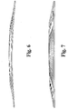
- FIG. 6 illustrates a cambered 144 x 98 cm bilayer 300 at room temperature after sintering at 1375°C for 1 hour.
- the composite mixture of the anode includes an amount of SiC sufficient to substantially reduce or eliminate this room temperature camber.
- the amount of SiC in the anode layer 120 can be any effective amount, but it will typically range from about 1 to about 20 volume % solids of the anode layer 120 after reduction, which corresponds to about 0.5 to about 10 % by weight.
- the SiC can be added to a particular anode layer, for example the bottom-most anode substrate layer of the individual piles of tape in FIG.
- the SiC is generally evenly dispersed through a substantial portion of the bulk anode layer 330, for example being evenly dispersed throughout substantially all of the bulk anode layer 330.
- a concentration in the lower end of the range may be employed, for example from 0.5 to 5 % by weight.
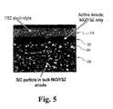
- An exemplary scanning electron micrograph of a SiC modified bilayer is depicted in FIG. 5 wherein it can be seen that the SiC particles are generally evenly dispersed throughout the bulk anode layer 330.
- One method of adding the SiC is to mix it in with the NiO and YSZ in either powder or fiber form prior to tape casting.
- a suitable particle size for the SiC corresponds to the particle size of the NiO and YSZ particles.
- the SiC ranges in average size between about 0.1 and 10 ⁇ m, for example having a mean size less that 1.0 ⁇ m, such as 0.4 ⁇ m.
- Commercial available SiC particles can be used, for example obtained from Superior Graphite, and they can be attrition milled to the desired average size.
- FIG. 7 illustrates the bilayer of FIG. 6 modified by the addition of 1 wt% SiC particles generally evenly dispersed throughout the bulk anode. Comparing FIGS. 6 and 7 , one can see that this SiC addition dramatically reduces the room temperature camber.
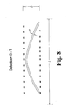
- FIG. 8 which is a side view of a cambered flat plate P
- the amount of camber is quantified by the centerpoint deflection, which is the distance D between the two imaginary parallel planes contacting the opposing sides of the plate P less the thickness T of the plate P. It is to be understood that the deflection will tend to increase with increasing length L of the undeflected plate P.
- the electrolyte-anode bilayer 300 has a length L greater than about 3cm and a thickness T less than about 750 ⁇ m and a room temperature deflection of less than about 0.05mm per cm of length L.
- the deflection is less than 0.02 or less than 0.01 mm per cm of length. In other aspects, these deflection metrics are achieved for a bilayer 300 less than 600 ⁇ m thick or less than 500 ⁇ m or less than 400 ⁇ m.
- a SOFC cell 100 can be formed from the anode-electrolyte bilayer 300 by any conventional method, for example by screen printing a cathode layer on the electrolyte layer followed by another sintering step.
- the formation of the cathode layer is done after the anode-electrolyte bilayer 300 has been cooled to room temperature, facilitating handling of the bilayer 300 for transport to another location or another processing operation.
- anode-electrolyte bilayers 300 may be mass produced at one location with the cathode layers applied and final SOFC formation done at another manufacturing location.
- silicon compounds may also be added to the anode in place of some or all of the SiC described above, for example, the oxides of silicon.
- the added SiC underwent the following decomposition reaction: SiC + 2O 2 -> SiO 2 + CO 2 it was found that roughly 18% of the SiC converted to SiO 2 during sintering at 1375 °C. Therefore the direct addition of a SiO x during construction of the anode should likewise lead to reduced camber in the completed anode-electrolyte bilayer.
- the amount of other silicon compounds added to the anode can range from 0-10% by weight. In general, when a mixture of silicon compounds is employed, the total amount of silicon compounds added (including any SiC) will be between 0.5 and 10% by weight. However, depending on the material selection, even lower amounts of silicon compounds can be effective. For example, while any of the various forms of the silicon oxides can be employed, the crystalline forms of SiO 2 have a TEC of around 9x10⁻⁶ /°C, whereas the amorphous fused silica has a TEC of around 0.5 x 10⁻⁶ /°C. Accordingly, it is anticipated that when fused silica is used, the overall amount of silicon compounds added can be lower than when only SiC and/or a combination of SiC and crystalline SiO x is used.
- a fuel cell constructed in accordance with the invention can have a wide variety of configurations, including, for example and without limitation, a planar fuel cell, a tubular fuel cell or a corrugated fuel cell.
- a planar fuel cell a tubular fuel cell or a corrugated fuel cell.
- multiple electrochemical cells are typically positioned adjacent one another in series to form a stack.
- planar solid oxide fuel cell stacks typically comprise a plurality of stacked cathode-electrode-anode-interconnect repeat units with an electrical interconnect between the cathode and the anode of adjacent cells.
- FIG. 2A A representative example of a cathode-electrode-anode-interconnect unit is set forth schematically in Figure 2A , wherein interconnect 140 is positioned adjacent anode 120.
- the fuel cell assembly can also include ducts or manifolding to conduct the fuel and oxidant into and out of the stack. Channels for gas flow, either in a cross-flow or a co-flow or a counterflow configuration, are usually incorporated into the cathode, anode and/or interconnect. Further information pertaining to various configurations that can advantageously be used in connection with the present invention is provided in commonly owned and copending U.S. Patent Application Ser. No. 10/134,072 filed April 26, 2002 entitled MULTI-LAYER SEAL FOR ELECTROCHEMICAL DEVICES.
- tubular SOFCs typically include an interior ceramic air electrode in the form of a porous tube.
- Some tubular SOFC designs also include a porous support tube on the interior of the cathode, which provides structural support for the tubular fuel cell, and also provides a substrate upon which other layers of the cell can be deposited during cell fabrication.
- the outer surface of the air electrode is mostly covered by a solid electrolyte material, typically made of YSZ.
- the outer surface of the solid electrolyte is covered by a cermet fuel electrode.
- air or oxygen is caused to flow through the center of the tube and a gaseous fuel is caused to contact the anode on the outside of the tube.
- the fuel cell is a planar fuel cell.
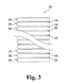
- an inventive fuel cell is incorporated in a fuel cell assembly 200 that includes a plurality of solid oxide fuel cells 240, 250, 260, 270, 280, 290.
- the individual cells are separated by seals 245, 255, 265, 275, 285, 295 and potentially one or more additional structures (not shown), such as, for example, conductive interconnects, gas flow components and the like.
- additional structures such as, for example, conductive interconnects, gas flow components and the like.
- the seals 245, 255, 265, 275, 285, 295 are omitted.
- One embodiment of the invention is a solid oxide fuel cell assembly for electrochemically reacting a fuel gas with a flowing oxidant gas at an elevated temperature to produce a DC output voltage, the assembly including a plurality of integral fuel cell units 240, 250, 260, 270, 280, 290, wherein each unit comprises a layer of ceramic ion conducting electrolyte disposed between and in contact with a conductive anode layer and a conductive cathode layer as described above, and wherein at least one unit includes a supporting anode layer as described herein.
- the assembly also preferably includes a system for passing a gaseous fuel in contact with said anode layers and passing an oxidizing gas in contact with said cathode layers (not shown); and a system for utilizing electrical energy produced by said fuel cells (not shown).
Landscapes
- Chemical & Material Sciences (AREA)
- Engineering & Computer Science (AREA)
- General Chemical & Material Sciences (AREA)
- Chemical Kinetics & Catalysis (AREA)
- Electrochemistry (AREA)
- Manufacturing & Machinery (AREA)
- Ceramic Engineering (AREA)
- Physics & Mathematics (AREA)
- Thermal Sciences (AREA)
- Life Sciences & Earth Sciences (AREA)
- Sustainable Development (AREA)
- Sustainable Energy (AREA)
- Composite Materials (AREA)
- Materials Engineering (AREA)
- Fuel Cell (AREA)
- Inert Electrodes (AREA)
Abstract
Description
- The present invention relates generally to the field of electrochemical devices, and more particularly but not exclusively to anode supported electrochemical cells and methods of fabrication. Materials and devices in accordance with the invention find advantageous use in solid oxide electrolyte electrochemical devices such as, for example, solid oxide fuel cells, electrolyzers, electrochemical sensors and the like.
- As a background to the invention, electrochemical devices based on solid oxide electrolytes have received, and continue to receive, significant attention. For example, solid state oxygen separation devices have received significant attention for the separation of pure oxygen from air. In addition, electrochemical fuel cell devices are believed to have significant potential for use as power sources. Fuel cell devices are known and used for the direct production of electricity from standard fuel materials including fossil fuels, hydrogen, and the like by converting chemical energy of a fuel into electrical energy. Fuel cells typically include a porous fuel electrode (also referred to as the "anode"), a porous air electrode (also referred to as the "cathode"), and a solid or liquid electrolyte therebetween. In operation, gaseous fuel materials are contacted, typically as a continuous stream, with the anode of the fuel cell system, while an oxidizing gas, for example air or oxygen, is allowed to pass in contact with the cathode of the system. Electrical energy is produced by electrochemical combination of the fuel with the oxidant. Because the fuel cells convert the chemical energy of the fuel directly into electricity without the intermediate thermal and mechanical energy step, their efficiency can be substantially higher than that of conventional methods of power generation.
- Solid oxide fuel cells (SOFCs) employing a dense ceramic electrolyte are currently considered as one of the most attractive technologies for electric power generation. In a typical SOFC, a solid electrolyte separates the porous metal-based anode from a porous metal or ceramic cathode. Due to its mechanical, electrical, chemical and thermal characteristics, yttria-stabilized zirconium oxide (YSZ) is currently the electrolyte material most commonly employed. At present, the anode in a typical SOFC is made of nickel-YSZ cermet, and the cathode is typically made of lanthanum manganites, lanthanum ferrites or lanthanum cobaltites. In such a fuel cell, an example of which is shown schematically in
Figure 1 , the fuel flowing to the anode reacts with oxide ions to produce electrons and water. The oxygen reacts with the electrons on the cathode surface to form oxide ions that migrate through the electrolyte to the anode. The electrons flow from the anode through an external circuit and then to the cathode. The movement of oxygen ions through the electrolyte maintains overall electrical charge balance, and the flow of electrons in the external circuit provides useful power. Useful fuels for fuel cell power generation include, for example, hydrogen, carbon monoxide, methane and hydrazine. - Because each individual electrochemical cell made of a single anode, a single electrolyte, and a single cathode generates an open circuit voltage of about one volt and each cell is subject to electrode activation polarization losses, electrical resistance losses, and ion mobility resistant losses which reduce its output to even lower voltages at a useful current, a fuel cell assembly comprising a plurality of fuel cell units electrically connected to each other to produce the desired voltage or current is required to generate commercially useful quantities of power.
- SOFCs typically operate at high temperatures, such as, for example, 650-1000°C. This allows flexibility in fuel choice and results in suitable fuel-to-electricity and thermal efficiencies; however, high temperatures impose stringent requirements on the materials selection for components of the fuel cell or fuel cell assembly. High operating temperatures also result in large thermal swings when the fuel cell is shut down and allowed to approach room temperature, either intentionally or accidentally. Because the different materials of the fuel cell invariably react differently to thermal cycling, i.e. they exhibit different thermal expansion coefficients; this thermal cycling can cause undesirable stress and lead to fluid leaks or structural breakdown.
- Even larger thermal swings might be experienced by portions of the fuel cell during fabrication. For example, it is common to form portions of a fuel cell via a process which entails sintering at high temperatures, for example 1000 - 1400°C. In order to increase the overall efficiency of the fuel cell is it desirable to reduce the thickness of the electrolyte membrane. This is accomplished by co-sintering the thin (1-15 µm) electrolyte with one of the electrodes as the primary support. Thermal expansion mismatches between the electrolyte and the electrode materials can result in undesirable stresses at material interfaces and/or the development of warping or camber when cooling from these high temperatures. Moreover, it is often desirable or necessary to utilize a series of thermal treatments to fully assembly a fuel cell. For example, an individual cell might be formed by first constructing an electrolyte-anode membrane in the first co-sintering operation. Then a cathode layer is applied to the electrolyte membrane and finished in a second co-sintering step. Alternately the cathode may be fired during the same sintering operation as the anode-electrolyte layers.
- Present efforts to develop commercially acceptable SOFCs that can be economically mass produced are hindered by the challenges presented by this thermal cycling and material property mismatch. For example, potential efficiencies to be gained through size reductions, for example by the construction of thin cells which utilize less materials and minimize gas diffusion distances, are offset by the need to overcome the challenges of thermal cycling.
- Accordingly, it is apparent that there is a continuing need for further developments in the field of SOFC technology. In particular, there is a need for further advancement in the development of materials and techniques that are practical and cost-effective yet can withstand the rigorous demands of manufacturing and use in advanced SOFC designs. The present invention addresses this need, and further provides related advantages.
- The present invention relates generally to systems and methods for forming electrochemical devices, and in particular supported electrolytes. While the actual nature of the invention covered herein can only be determined with reference to the claims appended hereto, certain forms of the invention that are characteristic of the embodiments disclosed herein are described briefly as follows.
- In one form of the present invention, a solid oxide fuel cell for electrochemically reacting a fuel gas with an oxidant gas to produce a DC output voltage comprises a layer of ceramic ion conducting electrolyte defining first and second opposing surfaces; a conductive anode layer facing the first surface of the electrolyte layer, wherein the conductive anode layer includes a bulk anode layer and an active anode layer; and a conductive cathode layer facing the second surface of the electrolyte layer; wherein the bulk anode layer includes between 0.5% and 10% by weight of a silicon compound selected from silicon carbide and silicon oxide.
- It is one object of the present invention to provide improved systems and methods for use in constructing electrochemical devices.
- Further objects, features, advantages, benefits, and further aspects of the present invention will become apparent from the drawings and description contained herein.
-
US4931168A discloses a gas permeable electrode which comprises a gas permeable layer and a reaction layer, the reaction layer comprising hydrophobic portions and hydrophilic portions. Electrolyte penetrates into the reaction layer and does not penetrate into the gas permeable layer, and only the gas produced on the electrode and the gas supplied penetrate into the gas permeable layer. The gas can be released from the rear side of the electrode and the reaction surface thereof is never covered with the gas. -
JP62184768A -
JP62232860A -
WO9728572 - Although the characteristic features of this invention will be particularly pointed out in the claims, the invention itself, and the manner in which it may be made and used, may be better understood by referring to the following description taken in connection with the accompanying figures forming a part hereof.
-
FIG. 1 depicts a general schematic diagram showing the function of a solid oxide fuel cell. -
FIG. 2 is a schematic diagram of an embodiment of a fuel cell in accordance with the invention. -
FIG. 2A is a schematic diagram of an embodiment of a fuel cell unit including an interconnect in accordance with the invention. -
FIG. 3 is a schematic diagram of an embodiment of an electrochemical device of the invention. -
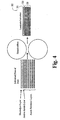
FIG. 4 is a schematic diagram of the roll lamination process used in the construction of anode-electrolyte bilayers. -
FIG. 5 is a scanning electron micrograph showing the microstructure of an anode-electrolyte bilayer with SiC particles in the bulk anode. -
FIG. 6 is a side perspective view of a reference anode-electrolyte bilayer at room temperature after sintering showing the undesirable formation of camber. -
FIG. 7 is a side perspective view of an anode-electrolyte bilayer with 1 wt% SiC added during construction of the bulk anode. TheFIG. 7 bilayer is also depicted at room temperature after sintering to show the reduction in camber relative to the reference bilayer ofFIG. 6 . -
FIG. 8 is a schematic side view of a cambered planar cell illustrating the method of quantifying the amount of camber. - For the purposes of promoting an understanding of the principles of the invention, reference will now be made to the embodiments illustrated in the drawings and specific language will be used to describe the same. It will nevertheless be understood that no limitation of the scope of the invention is hereby intended. Alterations and further modifications in the illustrated devices, and such further applications of the principles of the invention as illustrated herein are contemplated as would normally occur to one skilled in the art to which the invention relates.
- The present invention provides novel oxide electrode materials and fabrication techniques for solid oxide electrochemical devices such as, for example, electrodes for electrolyzers, electrodes for electrochemical sensors and anodes for solid oxide fuel cells. The invention also provides novel methods for making electrodes for electrochemical devices and electrochemical devices and assemblies having electrodes comprising inventive compositions. The invention is described herein primarily by reference to solid oxide fuel cell (SOFC) technology, and a variety of examples are provided herein showing advantageous features and characteristics of the invention in relation to SOFC technology; however, it is not intended that the invention be limited to use in connection with SOFC devices.
- It is well known to a person of ordinary skill in the relevant field that a SOFC can have a wide variety of configurations, including, for example and without limitation, a planar (also referred to as "flat plate") configuration, a tubular configuration and a corrugated configuration. The present invention is believed to address problems presented by material property mismatches, such as the mismatch in thermal expansion coefficient that leads to undesirable stresses and separations or cracking of layers in electrochemical devices. In the planar configuration presented and illustrated in the Figures, these problems are most noticeable and readily detectable, though not limited to, the development of undesirable warpage or camber of parts upon cooling from high temperatures. While the SOFC anode materials and methods provided by the present invention can be advantageously used in such planar configurations as a solution to the problem of camber development, it is to be understood that the anode materials can be used in a wide variety of SOFC configurations, and such are within the scope of the invention.
- As known in the art, a fuel cell is generally of a three-layer configuration as shown schematically in
Figure 2 , in whichfuel cell 100 includeselectrolyte layer 110,anode layer 120 andcathode layer 130.Anode layer 120 andcathode layer 130 are on opposite sides of theelectrolyte layer 110. - A solid oxide fuel cell can be made in accordance with one aspect of the invention by first providing an anode substrate and then applying an electrolyte layer to the anode substrate to form an anode-electrolyte bilayer. A cathode layer is then applied to the electrolyte. A fuel cell made in such a manner is generally referred to as an "anode-supported" cell.
- In other embodiments of the invention, a solid oxide fuel cell is made as an "electrolyte supported" or a "cathode-supported" fuel cell by using either the electrolyte or the cathode as the substrate to which the other layers are applied. In still other embodiments, particularly in methods for making fuel cells having a tubular construction, a porous inert substrate can be provided upon which each of the cathode, electrolyte and anode layers is sequentially applied.
- One manner of making the anode-electrolyte bilayer for an anode supported SOFC is to independently form the anode substrate, for example, by tape casting, tape calendering or other method that would occur to a person of ordinary skill in the art, and then to apply the electrolyte layer to the anode substrate. The electrolyte can be similarly formed (i.e. tape cast) and laminated together with the anode or it can be applied to the anode by a different procedure, such as, for example, painting, spraying, dip coating, screen printing or colloidal filtration/sedimentation.
- As described above, the
electrolyte layer 110 is a ceramic ionic conductor material, such as yttria-stabilized zirconia (YSZ), or ZrO2-8 mole % Y2O3, or any other material having similar properties. Several commercially available YSZ materials can be used including an HSY8.0 made by Daiichi and used in forming the bilayers ofFIGS. 6 and 7 . - The anode can be a nickel-YSZ cermet, which is composite mixture of the ceramic ionic conductor and an electric conductor. Generally, the nickel is provided in the form of NiO in the cermet and is subsequently converted to Ni by exposure to a reducing environment. The amount of Ni in the
anode layer 120 is sufficient to enable electrical conduction and performance of the electrochemical reaction and typically ranges from about 30-60 volume % solids after reduction, for example about 40 volume % of theanode layer 120 after reduction. In one aspect, theanode layer 120 is formed as a multi layer structure, having an active anode layer supported on a bulk anode layer, with the active anode layer facing the electrolyte layer. While the active and bulk anodes can be identical, because it serves primarily as a support substrate, the composition of the bulk anode layer may vary from that of the active anode. For example, the bulk anode may have a lower amount of Ni, such as about 40% by solids volume and be formed with a lower grade YSZ, for example a 5 mole% yittria composition. - As known in the art, anode and electrolyte materials can be tape cast by milling particles of the respective material (YSZ alone or YSZ and NiO) to a suitable particle size, such as approximately 0.1-5.0 µm, and forming a slurry with a suitable solvent, dispersant, binder and plasticizer. A suitable solvent is a mixture of Methyl ethyl ketone and ethanol. A suitable dispersant and binder is PS-21A from Witco and polyvinyl butyl (Butvar 79) from Solutia. A suitable plasticizer is Sanitizer S-160 from Monsanto. Upon drying, the individual layers of tape can be roll laminated between heater rollers. Suitable laminating conditions are 95-115°C at 30psi.
- As illustrated in
FIG. 4 , one technique utilizes single tape sheets of electrolyte and active anode and a number of tape sheets of the bulk anode to form a single laminated anode-electrolyte bilayer 300 which has a relativelythin electrolyte layer 310 on a relatively thinactive anode layer 320 all supported on a more substantialbulk anode layer 330. The laminated anode-electrolyte bilayer 300 is then sintered, for example at 1375°C for 1 hour. - After sintering the layer of
electrolyte 310 inbilayer 300 preferably has a thickness between 3 and 30 µm, for example between 5 and 15 µm, or about 8µm. Theactive anode 320 inbilayer 300 preferably has a thickness between 3 and 30 µm, for example between 5 and 15 µm, or about 8µm. Thebulk anode 330 inbilayer 300 preferably has a thickness between 200 and 1000 µm, for example between 400 and 600 µm, or about 550µm. - As the layers become thinner, and particularly when the
bilayer 300 is less than about 750-1000µm after sintering, the effects of material property mismatch begin to manifest in the development of camber. For example,FIG. 6 illustrates a cambered 144 x 98cm bilayer 300 at room temperature after sintering at 1375°C for 1 hour. - Surprising, it has been found that a relatively small amount of silicon carbide, SiC, added to the anode dramatically reduces the formation of camber. Accordingly, in one aspect of the invention, the composite mixture of the anode includes an amount of SiC sufficient to substantially reduce or eliminate this room temperature camber. The amount of SiC in the
anode layer 120 can be any effective amount, but it will typically range from about 1 to about 20 volume % solids of theanode layer 120 after reduction, which corresponds to about 0.5 to about 10 % by weight. The SiC can be added to a particular anode layer, for example the bottom-most anode substrate layer of the individual piles of tape inFIG. 4 , or more preferably the SiC is generally evenly dispersed through a substantial portion of thebulk anode layer 330, for example being evenly dispersed throughout substantially all of thebulk anode layer 330. When evenly dispersed throughout the bulk anode layer 330 a concentration in the lower end of the range may be employed, for example from 0.5 to 5 % by weight. An exemplary scanning electron micrograph of a SiC modified bilayer is depicted inFIG. 5 wherein it can be seen that the SiC particles are generally evenly dispersed throughout thebulk anode layer 330. - One method of adding the SiC is to mix it in with the NiO and YSZ in either powder or fiber form prior to tape casting. A suitable particle size for the SiC corresponds to the particle size of the NiO and YSZ particles. Alternatively, the SiC ranges in average size between about 0.1 and 10 µm, for example having a mean size less that 1.0µm, such as 0.4µm. Commercial available SiC particles can be used, for example obtained from Superior Graphite, and they can be attrition milled to the desired average size.
-
FIG. 7 illustrates the bilayer ofFIG. 6 modified by the addition of 1 wt% SiC particles generally evenly dispersed throughout the bulk anode. ComparingFIGS. 6 and 7 , one can see that this SiC addition dramatically reduces the room temperature camber. Referring to the dimensions depicted inFIG. 8 , which is a side view of a cambered flat plate P, the amount of camber is quantified by the centerpoint deflection, which is the distance D between the two imaginary parallel planes contacting the opposing sides of the plate P less the thickness T of the plate P. It is to be understood that the deflection will tend to increase with increasing length L of the undeflected plate P. Also, because a thicker plate P will have increased structural rigidity to resist camber, the deflection will tend to decrease with increasing thickness T of the plate P. In one form of the invention, the electrolyte-anode bilayer 300 has a length L greater than about 3cm and a thickness T less than about 750µm and a room temperature deflection of less than about 0.05mm per cm of length L. Preferably the deflection is less than 0.02 or less than 0.01 mm per cm of length. In other aspects, these deflection metrics are achieved for abilayer 300 less than 600µm thick or less than 500µm or less than 400µm. - A
SOFC cell 100 can be formed from the anode-electrolyte bilayer 300 by any conventional method, for example by screen printing a cathode layer on the electrolyte layer followed by another sintering step. In one aspect, the formation of the cathode layer is done after the anode-electrolyte bilayer 300 has been cooled to room temperature, facilitating handling of thebilayer 300 for transport to another location or another processing operation. For example, it is contemplated that anode-electrolyte bilayers 300 may be mass produced at one location with the cathode layers applied and final SOFC formation done at another manufacturing location. - It has also been found that the addition of these small amounts of SiC to the anode composition does not adversely effect performance of the SOFC. This is surprising given the substantial difference in thermal expansion coefficients (TEC) between traditional anode compositions and bulk SiC. For example, a typical YSZ anode that is 53% NiO has a TEC of about 12.5 x 10⁻⁶ /°C (over the relevant range, 30-1000°C), compared to about 5.5 x 10⁻⁶ /°C for SiC. This difference is significant considering the TEC for the zirconia electrolyte is about 10.5 x 10⁻⁶ /°C. Surprisingly, despite the substantial TEC difference, the presence of the inventive amounts of SiC in the anode does not cause degradation of the anode.
- In fact, it has been found that the addition of these small amounts of SiC not only do not adversely impact the performance of the cell, but in some cases actually increase the flexural strength of the bilayer, both before and after reduction and over a range of temperatures. While not intending to be bound by any theory, it is believed that the addition of SiC to the anode layer has an advantageous effect on two physical properties of the anode, its thermal expansion coefficient and its density. It is believed that the a SiC containing anode has a lower thermal expansion coefficient (TEC), bringing it closer to the TEC of the electrolyte. In addition, the SiC containing anode has an increased density, which is believed to contribute to the increased strength of the anode. Both of these changes, the lowered TEC and the increased density, are believed to each contribute to reduction of the undesirable room temperature camber.
- Other silicon compounds may also be added to the anode in place of some or all of the SiC described above, for example, the oxides of silicon. Using thermal gravimetric analysis and assuming that the added SiC underwent the following decomposition reaction:
SiC + 2O2 -> SiO2 + CO2
it was found that roughly 18% of the SiC converted to SiO2 during sintering at 1375 °C. Therefore the direct addition of a SiOx during construction of the anode should likewise lead to reduced camber in the completed anode-electrolyte bilayer. - The amount of other silicon compounds added to the anode can range from 0-10% by weight. In general, when a mixture of silicon compounds is employed, the total amount of silicon compounds added (including any SiC) will be between 0.5 and 10% by weight. However, depending on the material selection, even lower amounts of silicon compounds can be effective. For example, while any of the various forms of the silicon oxides can be employed, the crystalline forms of SiO2 have a TEC of around 9x10⁻⁶ /°C, whereas the amorphous fused silica has a TEC of around 0.5 x 10⁻⁶ /°C. Accordingly, it is anticipated that when fused silica is used, the overall amount of silicon compounds added can be lower than when only SiC and/or a combination of SiC and crystalline SiOx is used.
- A fuel cell constructed in accordance with the invention can have a wide variety of configurations, including, for example and without limitation, a planar fuel cell, a tubular fuel cell or a corrugated fuel cell. As a person of ordinary skill in the art will appreciate, with respect to planar SOFC designs, multiple electrochemical cells are typically positioned adjacent one another in series to form a stack. For example, planar solid oxide fuel cell stacks typically comprise a plurality of stacked cathode-electrode-anode-interconnect repeat units with an electrical interconnect between the cathode and the anode of adjacent cells. A representative example of a cathode-electrode-anode-interconnect unit is set forth schematically in
Figure 2A , whereininterconnect 140 is positionedadjacent anode 120. The fuel cell assembly can also include ducts or manifolding to conduct the fuel and oxidant into and out of the stack. Channels for gas flow, either in a cross-flow or a co-flow or a counterflow configuration, are usually incorporated into the cathode, anode and/or interconnect. Further information pertaining to various configurations that can advantageously be used in connection with the present invention is provided in commonly owned and copendingU.S. Patent Application Ser. No. 10/134,072 filed April 26, 2002 - With respect to tubular SOFC designs, conventional tubular SOFCs typically include an interior ceramic air electrode in the form of a porous tube. Some tubular SOFC designs also include a porous support tube on the interior of the cathode, which provides structural support for the tubular fuel cell, and also provides a substrate upon which other layers of the cell can be deposited during cell fabrication. The outer surface of the air electrode is mostly covered by a solid electrolyte material, typically made of YSZ. The outer surface of the solid electrolyte is covered by a cermet fuel electrode. In use of a tubular SOFC device, air or oxygen is caused to flow through the center of the tube and a gaseous fuel is caused to contact the anode on the outside of the tube.
- It is, of course, understood that there are many design possibilities for fuel cells within these and other categories. Examples of different configurations are provided, for example, in
U.S. Patent No. 5,993,986 to Wallin et al. ;U.S. Patent No. 6,106,967 to Virkar et al. ,U.S. Patent No. 5,238,754 to Yasuo et al. ,U.S. Patent No. 4,997,726 to Akiyama et al. ,U.S. Patent No. 4,761,349 to McPheeters et al. ,U.S. Patent No. 5,827,620 to Kendall ,U.S. Patent No. 6,248,468 to Ruka et al. ,U.S. Patent No. 5,258,240 to Di Croce et al .,U.S. Patent No. 5,932,146 to Kuo et al. andU.S. Patent No. 4,849,254 to Spengler et al . It is, of course, not intended that the invention be limited to these exemplary configurations. The present invention contemplates the use in all such fuel cell configurations now known or later developed, without limitation to particulars of the design. In a preferred embodiment, the fuel cell is a planar fuel cell. - In one aspect of the invention, depicted schematically in
Figure 3 , an inventive fuel cell is incorporated in afuel cell assembly 200 that includes a plurality of solidoxide fuel cells seals seals fuel cell units - While the invention has been illustrated and described in detail in the drawings and foregoing description, the same is to be considered as illustrative and not restrictive in character. Any experiments, experimental examples, or experimental results provided herein are intended to be illustrative of the present invention and should not be considered limiting or restrictive with regard to the invention scope. Further, any theory, mechanism of operation, proof, or finding stated herein is meant to further enhance understanding of the present invention and is not intended to limit the present invention in any way to such theory, mechanism of operation, proof, or finding. Thus, the specifies of this description and the attached drawings should not be interpreted to limit the scope of this invention to the specifics thereof. Rather, the scope of this invention should be evaluated with reference to the claims appended hereto. In reading the claims it is intended that when words such as "a", "an", "at least one", and "at least a portion" are used there is no intention to limit the claims to only one item unless specifically stated to the contrary in the claims. Further, when the language "at least a portion" and/or "a portion" is used, the claims may include a portion and/or the entire items unless specifically stated to the contrary. Likewise, where the term "input" or "output" is used in connection with reference to an electronic device, it should be understood to comprehend singular or plural and one or more signal channels as appropriate in the context.
Claims (7)
- A solid oxide fuel cell (100) for electrochemically reacting a fuel gas with an oxidant gas to produce a DC output voltage, said solid oxide fuel cell (100) comprising:a layer of ceramic ion conducting electrolyte (110) defining first and second opposing surfaces;a conductive anode layer (120) facing the first surface of the electrolyte layer (110), wherein the conductive anode layer (120) includes a bulk anode layer (330) and an active anode layer (320); anda conductive cathode layer (130) facing the second surface of the electrolyte layer (110);wherein the bulk anode layer (330) includes between 0.5% and 10% by weight of a silicon compound selected from silicon carbide and silicon oxide.
- The solid oxide fuel cell (100) of claim 1 wherein the bulk anode layer (330) comprises at least 0.75% by weight silicon carbide.
- The solid oxide fuel cell (100) of claim 2 wherein the active anode layer (320) is devoid of the silicon compound.
- The solid oxide fuel cell (100) of claim 2 wherein the active anode layer (320) is thinner than the bulk anode layer.
- The solid oxide fuel cell (100) of claim 2, 3 or 4 wherein the bulk anode layer (330) is of a thickness greater than the combined thickness of the active anode layer (320), the layer of ceramic ion conducting electrolyte (110), and the conductive cathode layer (130).
- The solid oxide fuel cell (100) of claim 5 wherein the bulk anode layer (330) is of a thickness less than 750 µm.
- The solid oxide fuel cell (100) of claim 1, 2 or 3 wherein the ceramic ion conducting electrolyte (110) is a yttria-stabilized zirconia and the conductive anode layer (320) contains between 30 and 60 % nickel by volume.
Applications Claiming Priority (2)
| Application Number | Priority Date | Filing Date | Title |
|---|---|---|---|
| US10/425,858 US7244526B1 (en) | 2003-04-28 | 2003-04-28 | Solid oxide fuel cell anodes and electrodes for other electrochemical devices |
| PCT/US2004/012889 WO2004097959A2 (en) | 2003-04-28 | 2004-04-27 | Solid oxide fuel cell anodes and electrodes for other electrochemical devices |
Publications (3)
| Publication Number | Publication Date |
|---|---|
| EP1620908A2 EP1620908A2 (en) | 2006-02-01 |
| EP1620908A4 EP1620908A4 (en) | 2009-03-04 |
| EP1620908B1 true EP1620908B1 (en) | 2011-02-23 |
Family
ID=33415925
Family Applications (1)
| Application Number | Title | Priority Date | Filing Date |
|---|---|---|---|
| EP04760402A Expired - Lifetime EP1620908B1 (en) | 2003-04-28 | 2004-04-27 | Solid oxide fuel cell anodes and electrodes for other electrochemical devices |
Country Status (8)
| Country | Link |
|---|---|
| US (2) | US7244526B1 (en) |
| EP (1) | EP1620908B1 (en) |
| JP (1) | JP2006524902A (en) |
| AT (1) | ATE499721T1 (en) |
| CA (1) | CA2520858C (en) |
| DE (1) | DE602004031518D1 (en) |
| DK (1) | DK1620908T3 (en) |
| WO (1) | WO2004097959A2 (en) |
Families Citing this family (22)
| Publication number | Priority date | Publication date | Assignee | Title |
|---|---|---|---|---|
| US7595085B2 (en) * | 2004-03-09 | 2009-09-29 | Delphi Technologies, Inc. | Ceramic assembly with a stabilizer layer |
| AU2004319545A1 (en) * | 2004-05-17 | 2005-11-24 | Nippon Shokubai Co., Ltd. | Anode supporting substrate for solid oxide fuel cell and process for producing the same |
| US7658773B2 (en) * | 2006-09-29 | 2010-02-09 | Qimonda Ag | Method for fabricating a solid electrolyte memory device and solid electrolyte memory device |
| TR200605864A2 (en) * | 2006-10-19 | 2007-03-21 | Vestel Elektroni̇k Sanayi̇ Ve Ti̇caret A.Ş. | Membrane electrode assembly for solid oxide fuel cell. |
| JP5172207B2 (en) * | 2006-10-24 | 2013-03-27 | 日本碍子株式会社 | Thin plate for single cell of solid oxide fuel cell |
| ES2394194T3 (en) * | 2006-11-23 | 2013-01-23 | Technical University Of Denmark | Method for the production of reversible cells of solid oxides |
| JP5237614B2 (en) * | 2007-05-22 | 2013-07-17 | 日本碍子株式会社 | Solid oxide fuel cell |
| KR100889266B1 (en) * | 2007-07-30 | 2009-03-19 | 한국과학기술원 | Combined structure between unit cell and separator of solid oxide fuel cell |
| EP2031681A1 (en) * | 2007-08-31 | 2009-03-04 | The Technical University of Denmark | Horizontally graded structures for electrochemical and electronic devices |
| US8828618B2 (en) * | 2007-12-07 | 2014-09-09 | Nextech Materials, Ltd. | High performance multilayer electrodes for use in reducing gases |
| US20090148743A1 (en) * | 2007-12-07 | 2009-06-11 | Day Michael J | High performance multilayer electrodes for use in oxygen-containing gases |
| EP2107630B1 (en) * | 2008-04-03 | 2011-08-31 | Institute of Nuclear Energy Research Atomic Energy Council, Executive Yuan | Process for anode treatment of a membrane electrode assembly of a solid oxide fuel cell |
| US8182965B2 (en) * | 2008-09-30 | 2012-05-22 | Battelle Memorial Institute | Optimized cell configurations for stable LSCF-based solid oxide fuel cells |
| KR101741849B1 (en) * | 2008-12-08 | 2017-05-30 | 넥스테크 머티리얼스, 엘티디. | Current collectors for solid oxide fuel cell stacks |
| WO2011036972A1 (en) * | 2009-09-25 | 2011-03-31 | 日本碍子株式会社 | Cell of solid oxide fuel cell |
| JP6014304B2 (en) * | 2010-01-15 | 2016-10-25 | ユー・ディー・シー アイルランド リミテッド | Organic electroluminescence device |
| WO2012024330A2 (en) | 2010-08-17 | 2012-02-23 | Bloom Energy Corporation | Method for solid oxide fuel cell fabrication |
| JP5932232B2 (en) * | 2011-03-25 | 2016-06-08 | 株式会社日本触媒 | Anode-supported half cell, anode-supported cell using the same, and method for producing anode-supported half-cell |
| JP6842798B2 (en) * | 2016-04-11 | 2021-03-17 | フュエルセル エナジー, インコーポレイテッドFuelcell Energy, Inc. | Supported nickel catalyst used as a direct internal reforming catalyst in molten carbonate fuel cells |
| JP6060297B2 (en) * | 2016-04-28 | 2017-01-11 | 株式会社日本触媒 | Anode-supported half cell and anode-supported cell using the same |
| CN113381048B (en) * | 2021-05-28 | 2022-11-11 | 山东工业陶瓷研究设计院有限公司 | Solid oxide fuel cell and preparation method thereof |
| CN118553947B (en) * | 2024-05-31 | 2025-11-07 | 紫金矿业集团股份有限公司 | Fuel electrode support SOC unit and preparation method |
Family Cites Families (42)
| Publication number | Priority date | Publication date | Assignee | Title |
|---|---|---|---|---|
| US4362788A (en) * | 1981-03-11 | 1982-12-07 | Energy Research Corporation | Fuel cell system with anode and cathodes operating at different pressures |
| JPS61158883A (en) * | 1984-12-28 | 1986-07-18 | 日本特殊陶業株式会社 | Coated zirconia base sintered body |
| JPH065619B2 (en) * | 1986-02-06 | 1994-01-19 | 田中貴金属工業株式会社 | Method for manufacturing gas diffusion electrode |
| EP0241432B1 (en) * | 1986-03-07 | 1993-08-11 | Tanaka Kikinzoku Kogyo K.K. | Gas permeable electrode |
| JPS62232860A (en) * | 1986-04-01 | 1987-10-13 | Tanaka Kikinzoku Kogyo Kk | Gas diffusion electrode and manufacture thereof |
| US4952466A (en) * | 1987-01-16 | 1990-08-28 | The Dow Chemical Company | Solid electrolyte battery |
| JPH0785416B2 (en) * | 1987-01-21 | 1995-09-13 | 三菱電機株式会社 | Gas seal manufacturing method for phosphoric acid fuel cell |
| US4920015A (en) * | 1988-09-29 | 1990-04-24 | Gas Research Institute | Electrochemical H2 S conversion |
| EP0378812A1 (en) * | 1989-01-18 | 1990-07-25 | Asea Brown Boveri Ag | Arrangement of fuel cells based on a solid electrolyte operating at a high temperature, consisting of zirconium oxide, to obtain maximum possible power |
| US4910100A (en) * | 1989-07-21 | 1990-03-20 | Fuji Electric Co., Ltd. | Solid electrolyte fuel cell |
| US5059497A (en) * | 1990-04-20 | 1991-10-22 | Hughes Aircraft Company | Composite ion-conductive electrolyte member |
| US5069987A (en) * | 1990-07-06 | 1991-12-03 | Igr Enterprises, Inc. | Solid oxide fuel cell assembly |
| US5230849A (en) * | 1991-06-04 | 1993-07-27 | Michael S. Hsu | Electrochemical converter assembly and overlay methods of forming component structures |
| US5162166A (en) * | 1991-07-19 | 1992-11-10 | Kerr-Mcgee Corporation | Devices providing electrical energy from fuel/oxygen mixtures |
| US5750279A (en) * | 1992-02-28 | 1998-05-12 | Air Products And Chemicals, Inc. | Series planar design for solid electrolyte oxygen pump |
| CA2139167C (en) * | 1993-12-29 | 1997-12-02 | Keijiro Yamashita | Electrode used in electrochemical reaction and fuel cell using the same |
| US5702837A (en) * | 1996-02-05 | 1997-12-30 | Alliedsignal Inc. | Bonding materials for anode to anode bonding and anode to interconnect bonding in solid oxide fuel cells |
| US5858314A (en) * | 1996-04-12 | 1999-01-12 | Ztek Corporation | Thermally enhanced compact reformer |
| JP3193294B2 (en) * | 1996-05-24 | 2001-07-30 | 財団法人ファインセラミックスセンター | Composite ceramic powder, method for producing the same, electrode for solid oxide fuel cell, and method for producing the same |
| US5964991A (en) * | 1996-09-26 | 1999-10-12 | Ngk Insulators, Ltd. | Sintered laminated structures, electrochemical cells and process for producing such sintered laminated structures |
| US5911860A (en) * | 1996-12-31 | 1999-06-15 | Praxair Technology, Inc. | Solid electrolyte membrane with mechanically-enhancing constituents |
| US6187157B1 (en) * | 1996-12-31 | 2001-02-13 | Praxair Technology, Inc. | Multi-phase solid electrolyte ionic transport membrane and method for fabricating same |
| US6332964B1 (en) * | 1996-12-31 | 2001-12-25 | Praxair Technology, Inc. | Multi-phase solid ion and electron conducting membrane with low volume percentage electron conducting phase and methods for fabricating |
| JPH10241702A (en) * | 1997-02-28 | 1998-09-11 | Mitsubishi Heavy Ind Ltd | Fuel electrode of solid electrolyte type electrochemical cell |
| US5935727A (en) * | 1997-04-10 | 1999-08-10 | The Dow Chemical Company | Solid oxide fuel cells |
| US6228520B1 (en) * | 1997-04-10 | 2001-05-08 | The Dow Chemical Company | Consinterable ceramic interconnect for solid oxide fuel cells |
| US6358567B2 (en) * | 1998-12-23 | 2002-03-19 | The Regents Of The University Of California | Colloidal spray method for low cost thin coating deposition |
| WO2001003212A2 (en) * | 1999-07-05 | 2001-01-11 | Siemens Aktiengesellschaft | High-temperature polymer electrolyte membrane (htm) fuel cell, htm fuel cell system, method for operating an htm fuel cell and/or an htm fuel cell system |
| FR2796861B1 (en) * | 1999-07-26 | 2001-11-09 | Air Liquide | NOVEL OXIDIZED CONDUCTIVE CERAMIC MEMBRANE, USE OF SAID MEMBRANE FOR SEPARATING OXYGEN FROM AIR OR A GASEOUS MIXTURE CONTAINING IT |
| DE10044703B4 (en) * | 2000-09-09 | 2013-10-17 | Elringklinger Ag | Fuel cell unit, fuel cell block assembly and method for producing a fuel cell block assembly |
| JP2002141580A (en) | 2000-11-01 | 2002-05-17 | Fujitsu Ltd | Magnetoresistive film and method of manufacturing the same |
| US6613468B2 (en) * | 2000-12-22 | 2003-09-02 | Delphi Technologies, Inc. | Gas diffusion mat for fuel cells |
| US6824910B2 (en) * | 2001-01-24 | 2004-11-30 | The Regents Of The University Of California | Co-flow planar SOFC fuel cell stack |
| US20020127455A1 (en) * | 2001-03-08 | 2002-09-12 | The Regents Of The University Of California | Ceria-based solid oxide fuel cells |
| US6811741B2 (en) * | 2001-03-08 | 2004-11-02 | The Regents Of The University Of California | Method for making thick and/or thin film |
| US20020127460A1 (en) * | 2001-03-08 | 2002-09-12 | The Regents Of The University Of California | Protective coatings for fuel cell interconnect |
| US6803141B2 (en) * | 2001-03-08 | 2004-10-12 | The Regents Of The University Of California | High power density solid oxide fuel cells |
| US6815116B2 (en) * | 2001-03-08 | 2004-11-09 | The Regents Of The University Of California | Flexible interconnects for fuel cell stacks |
| US20030096147A1 (en) * | 2001-11-21 | 2003-05-22 | Badding Michael E. | Solid oxide fuel cell stack and packet designs |
| CA2440288A1 (en) * | 2002-09-10 | 2004-03-10 | Alberta Research Council Inc. | Crack-resistant anode-supported fuel cell |
| US6858045B2 (en) * | 2002-11-29 | 2005-02-22 | Praxair Technology, Inc. | Method of manufacturing an electrolytic cell |
| US7029777B2 (en) * | 2003-04-10 | 2006-04-18 | Hewlett-Packard Development Company, L.P. | Fuel cell and passive support |
-
2003
- 2003-04-28 US US10/425,858 patent/US7244526B1/en not_active Expired - Lifetime
-
2004
- 2004-04-27 DK DK04760402.0T patent/DK1620908T3/en active
- 2004-04-27 EP EP04760402A patent/EP1620908B1/en not_active Expired - Lifetime
- 2004-04-27 AT AT04760402T patent/ATE499721T1/en not_active IP Right Cessation
- 2004-04-27 DE DE602004031518T patent/DE602004031518D1/en not_active Expired - Lifetime
- 2004-04-27 JP JP2006513351A patent/JP2006524902A/en active Pending
- 2004-04-27 WO PCT/US2004/012889 patent/WO2004097959A2/en not_active Ceased
- 2004-04-27 CA CA2520858A patent/CA2520858C/en not_active Expired - Fee Related
-
2007
- 2007-05-30 US US11/755,087 patent/US7455700B2/en not_active Expired - Fee Related
Also Published As
| Publication number | Publication date |
|---|---|
| EP1620908A4 (en) | 2009-03-04 |
| US20070172719A1 (en) | 2007-07-26 |
| WO2004097959A8 (en) | 2005-01-13 |
| ATE499721T1 (en) | 2011-03-15 |
| DK1620908T3 (en) | 2011-03-21 |
| US20070220721A1 (en) | 2007-09-27 |
| JP2006524902A (en) | 2006-11-02 |
| DE602004031518D1 (en) | 2011-04-07 |
| CA2520858C (en) | 2013-07-23 |
| EP1620908A2 (en) | 2006-02-01 |
| US7244526B1 (en) | 2007-07-17 |
| WO2004097959A2 (en) | 2004-11-11 |
| CA2520858A1 (en) | 2004-11-11 |
| WO2004097959A3 (en) | 2005-08-11 |
| US7455700B2 (en) | 2008-11-25 |
Similar Documents
| Publication | Publication Date | Title |
|---|---|---|
| US7455700B2 (en) | Method for creating solid oxide fuel cell anodes and electrodes for other electrochemical devices | |
| US6653009B2 (en) | Solid oxide fuel cells and interconnectors | |
| EP2380231B1 (en) | Thermal shock-tolerant solid oxide fuel cell stack | |
| JP4960593B2 (en) | Electrochemical battery stack assembly | |
| US7645535B2 (en) | Method and materials for bonding electrodes to interconnect layers in solid oxide fuel cell stacks | |
| US7767358B2 (en) | Supported ceramic membranes and electrochemical cells and cell stacks including the same | |
| US8354202B2 (en) | Multilayer glass-ceramic seals for fuel cells | |
| EP2229702B1 (en) | Ceramic interconnect for fuel cell stacks | |
| CN100530766C (en) | Sealed joint structure for electrochemical device | |
| KR101162806B1 (en) | Self-supporting ceramic membranes and electrochemical cells and electrochemical cell stacks including the same | |
| US20060024547A1 (en) | Anode supported sofc with an electrode multifunctional layer | |
| KR20000059873A (en) | Single Cell and Stack Structure of Solid Oxide Fuel Cell | |
| US20050095483A1 (en) | Anode-supported flat-tubular solid oxide fuel cell stack and fabrication method of the same | |
| JP5671196B2 (en) | Reinforced electrode-supported ceramic fuel cell and manufacturing method | |
| US7351491B2 (en) | Supporting electrodes for solid oxide fuel cells and other electrochemical devices | |
| KR101983534B1 (en) | Method of manufacturing substrate-supported ceramic interconnect and substrate-supported ceramic interconnect thereof | |
| JPH10172590A (en) | Solid oxide fuel cell | |
| JP5079991B2 (en) | Fuel cell and fuel cell | |
| KR20120037175A (en) | A fuel cell and a manufacturing metheod thereof | |
| JPH09129252A (en) | Highly durable solid electrolyte fuel cell and method for manufacturing the same | |
| JP3166888B2 (en) | Solid oxide fuel cell stack | |
| CN111244498A (en) | Fuel cell and fuel cell stack | |
| TW202412369A (en) | Electrochemical cell | |
| JPH07320756A (en) | Solid electrolyte fuel cell | |
| JPH03238758A (en) | Solid electrolyte fuel cell |
Legal Events
| Date | Code | Title | Description |
|---|---|---|---|
| PUAI | Public reference made under article 153(3) epc to a published international application that has entered the european phase |
Free format text: ORIGINAL CODE: 0009012 |
|
| 17P | Request for examination filed |
Effective date: 20050923 |
|
| AK | Designated contracting states |
Kind code of ref document: A2 Designated state(s): AT BE BG CH CY CZ DE DK EE ES FI FR GB GR HU IE IT LI LU MC NL PL PT RO SE SI SK TR |
|
| AX | Request for extension of the european patent |
Extension state: AL HR LT LV MK |
|
| DAX | Request for extension of the european patent (deleted) | ||
| A4 | Supplementary search report drawn up and despatched |
Effective date: 20090203 |
|
| RIC1 | Information provided on ipc code assigned before grant |
Ipc: H01M 8/12 20060101AFI20090128BHEP Ipc: H01M 4/88 20060101ALI20090128BHEP Ipc: H01M 4/86 20060101ALI20090128BHEP |
|
| RIC1 | Information provided on ipc code assigned before grant |
Ipc: H01M 8/00 20060101AFI20090804BHEP |
|
| 17Q | First examination report despatched |
Effective date: 20091005 |
|
| GRAP | Despatch of communication of intention to grant a patent |
Free format text: ORIGINAL CODE: EPIDOSNIGR1 |
|
| RIC1 | Information provided on ipc code assigned before grant |
Ipc: H01M 8/12 20060101AFI20100910BHEP Ipc: H01M 4/86 20060101ALI20100910BHEP Ipc: H01M 4/88 20060101ALI20100910BHEP |
|
| GRAS | Grant fee paid |
Free format text: ORIGINAL CODE: EPIDOSNIGR3 |
|
| GRAA | (expected) grant |
Free format text: ORIGINAL CODE: 0009210 |
|
| AK | Designated contracting states |
Kind code of ref document: B1 Designated state(s): AT BE BG CH CY CZ DE DK EE ES FI FR GB GR HU IE IT LI LU MC NL PL PT RO SE SI SK TR |
|
| REG | Reference to a national code |
Ref country code: GB Ref legal event code: FG4D |
|
| REG | Reference to a national code |
Ref country code: CH Ref legal event code: EP |
|
| REG | Reference to a national code |
Ref country code: DK Ref legal event code: T3 |
|
| REG | Reference to a national code |
Ref country code: IE Ref legal event code: FG4D |
|
| REF | Corresponds to: |
Ref document number: 602004031518 Country of ref document: DE Date of ref document: 20110407 Kind code of ref document: P |
|
| REG | Reference to a national code |
Ref country code: DE Ref legal event code: R096 Ref document number: 602004031518 Country of ref document: DE Effective date: 20110407 |
|
| REG | Reference to a national code |
Ref country code: NL Ref legal event code: VDEP Effective date: 20110223 |
|
| PG25 | Lapsed in a contracting state [announced via postgrant information from national office to epo] |
Ref country code: GR Free format text: LAPSE BECAUSE OF FAILURE TO SUBMIT A TRANSLATION OF THE DESCRIPTION OR TO PAY THE FEE WITHIN THE PRESCRIBED TIME-LIMIT Effective date: 20110524 Ref country code: PT Free format text: LAPSE BECAUSE OF FAILURE TO SUBMIT A TRANSLATION OF THE DESCRIPTION OR TO PAY THE FEE WITHIN THE PRESCRIBED TIME-LIMIT Effective date: 20110623 Ref country code: SE Free format text: LAPSE BECAUSE OF FAILURE TO SUBMIT A TRANSLATION OF THE DESCRIPTION OR TO PAY THE FEE WITHIN THE PRESCRIBED TIME-LIMIT Effective date: 20110223 Ref country code: ES Free format text: LAPSE BECAUSE OF FAILURE TO SUBMIT A TRANSLATION OF THE DESCRIPTION OR TO PAY THE FEE WITHIN THE PRESCRIBED TIME-LIMIT Effective date: 20110603 |
|
| PG25 | Lapsed in a contracting state [announced via postgrant information from national office to epo] |
Ref country code: BG Free format text: LAPSE BECAUSE OF FAILURE TO SUBMIT A TRANSLATION OF THE DESCRIPTION OR TO PAY THE FEE WITHIN THE PRESCRIBED TIME-LIMIT Effective date: 20110523 Ref country code: NL Free format text: LAPSE BECAUSE OF FAILURE TO SUBMIT A TRANSLATION OF THE DESCRIPTION OR TO PAY THE FEE WITHIN THE PRESCRIBED TIME-LIMIT Effective date: 20110223 Ref country code: CY Free format text: LAPSE BECAUSE OF FAILURE TO SUBMIT A TRANSLATION OF THE DESCRIPTION OR TO PAY THE FEE WITHIN THE PRESCRIBED TIME-LIMIT Effective date: 20110223 Ref country code: BE Free format text: LAPSE BECAUSE OF FAILURE TO SUBMIT A TRANSLATION OF THE DESCRIPTION OR TO PAY THE FEE WITHIN THE PRESCRIBED TIME-LIMIT Effective date: 20110223 Ref country code: FI Free format text: LAPSE BECAUSE OF FAILURE TO SUBMIT A TRANSLATION OF THE DESCRIPTION OR TO PAY THE FEE WITHIN THE PRESCRIBED TIME-LIMIT Effective date: 20110223 Ref country code: SI Free format text: LAPSE BECAUSE OF FAILURE TO SUBMIT A TRANSLATION OF THE DESCRIPTION OR TO PAY THE FEE WITHIN THE PRESCRIBED TIME-LIMIT Effective date: 20110223 Ref country code: AT Free format text: LAPSE BECAUSE OF FAILURE TO SUBMIT A TRANSLATION OF THE DESCRIPTION OR TO PAY THE FEE WITHIN THE PRESCRIBED TIME-LIMIT Effective date: 20110223 |
|
| PG25 | Lapsed in a contracting state [announced via postgrant information from national office to epo] |
Ref country code: EE Free format text: LAPSE BECAUSE OF FAILURE TO SUBMIT A TRANSLATION OF THE DESCRIPTION OR TO PAY THE FEE WITHIN THE PRESCRIBED TIME-LIMIT Effective date: 20110223 |
|
| PG25 | Lapsed in a contracting state [announced via postgrant information from national office to epo] |
Ref country code: RO Free format text: LAPSE BECAUSE OF FAILURE TO SUBMIT A TRANSLATION OF THE DESCRIPTION OR TO PAY THE FEE WITHIN THE PRESCRIBED TIME-LIMIT Effective date: 20110223 Ref country code: MC Free format text: LAPSE BECAUSE OF NON-PAYMENT OF DUE FEES Effective date: 20110430 Ref country code: SK Free format text: LAPSE BECAUSE OF FAILURE TO SUBMIT A TRANSLATION OF THE DESCRIPTION OR TO PAY THE FEE WITHIN THE PRESCRIBED TIME-LIMIT Effective date: 20110223 Ref country code: CZ Free format text: LAPSE BECAUSE OF FAILURE TO SUBMIT A TRANSLATION OF THE DESCRIPTION OR TO PAY THE FEE WITHIN THE PRESCRIBED TIME-LIMIT Effective date: 20110223 |
|
| REG | Reference to a national code |
Ref country code: CH Ref legal event code: PL |
|
| PLBE | No opposition filed within time limit |
Free format text: ORIGINAL CODE: 0009261 |
|
| STAA | Information on the status of an ep patent application or granted ep patent |
Free format text: STATUS: NO OPPOSITION FILED WITHIN TIME LIMIT |
|
| PG25 | Lapsed in a contracting state [announced via postgrant information from national office to epo] |
Ref country code: CH Free format text: LAPSE BECAUSE OF NON-PAYMENT OF DUE FEES Effective date: 20110430 Ref country code: LI Free format text: LAPSE BECAUSE OF NON-PAYMENT OF DUE FEES Effective date: 20110430 |
|
| 26N | No opposition filed |
Effective date: 20111124 |
|
| REG | Reference to a national code |
Ref country code: IE Ref legal event code: MM4A |
|
| PG25 | Lapsed in a contracting state [announced via postgrant information from national office to epo] |
Ref country code: PL Free format text: LAPSE BECAUSE OF FAILURE TO SUBMIT A TRANSLATION OF THE DESCRIPTION OR TO PAY THE FEE WITHIN THE PRESCRIBED TIME-LIMIT Effective date: 20110223 |
|
| REG | Reference to a national code |
Ref country code: DE Ref legal event code: R097 Ref document number: 602004031518 Country of ref document: DE Effective date: 20111124 |
|
| PG25 | Lapsed in a contracting state [announced via postgrant information from national office to epo] |
Ref country code: IE Free format text: LAPSE BECAUSE OF NON-PAYMENT OF DUE FEES Effective date: 20110427 |
|
| PGFP | Annual fee paid to national office [announced via postgrant information from national office to epo] |
Ref country code: GB Payment date: 20120327 Year of fee payment: 9 Ref country code: DK Payment date: 20120327 Year of fee payment: 9 |
|
| PGFP | Annual fee paid to national office [announced via postgrant information from national office to epo] |
Ref country code: DE Payment date: 20120430 Year of fee payment: 9 |
|
| PGFP | Annual fee paid to national office [announced via postgrant information from national office to epo] |
Ref country code: IT Payment date: 20120420 Year of fee payment: 9 |
|
| PG25 | Lapsed in a contracting state [announced via postgrant information from national office to epo] |
Ref country code: LU Free format text: LAPSE BECAUSE OF NON-PAYMENT OF DUE FEES Effective date: 20110427 |
|
| PGFP | Annual fee paid to national office [announced via postgrant information from national office to epo] |
Ref country code: FR Payment date: 20130417 Year of fee payment: 10 |
|
| PG25 | Lapsed in a contracting state [announced via postgrant information from national office to epo] |
Ref country code: TR Free format text: LAPSE BECAUSE OF FAILURE TO SUBMIT A TRANSLATION OF THE DESCRIPTION OR TO PAY THE FEE WITHIN THE PRESCRIBED TIME-LIMIT Effective date: 20110223 |
|
| PG25 | Lapsed in a contracting state [announced via postgrant information from national office to epo] |
Ref country code: HU Free format text: LAPSE BECAUSE OF FAILURE TO SUBMIT A TRANSLATION OF THE DESCRIPTION OR TO PAY THE FEE WITHIN THE PRESCRIBED TIME-LIMIT Effective date: 20110223 |
|
| REG | Reference to a national code |
Ref country code: DK Ref legal event code: EBP Effective date: 20130430 |
|
| GBPC | Gb: european patent ceased through non-payment of renewal fee |
Effective date: 20130427 |
|
| PG25 | Lapsed in a contracting state [announced via postgrant information from national office to epo] |
Ref country code: DE Free format text: LAPSE BECAUSE OF NON-PAYMENT OF DUE FEES Effective date: 20131101 Ref country code: GB Free format text: LAPSE BECAUSE OF NON-PAYMENT OF DUE FEES Effective date: 20130427 |
|
| REG | Reference to a national code |
Ref country code: DE Ref legal event code: R119 Ref document number: 602004031518 Country of ref document: DE Effective date: 20131101 |
|
| PG25 | Lapsed in a contracting state [announced via postgrant information from national office to epo] |
Ref country code: IT Free format text: LAPSE BECAUSE OF NON-PAYMENT OF DUE FEES Effective date: 20130427 |
|
| PG25 | Lapsed in a contracting state [announced via postgrant information from national office to epo] |
Ref country code: DK Free format text: LAPSE BECAUSE OF NON-PAYMENT OF DUE FEES Effective date: 20130430 |
|
| REG | Reference to a national code |
Ref country code: FR Ref legal event code: ST Effective date: 20141231 |
|
| PG25 | Lapsed in a contracting state [announced via postgrant information from national office to epo] |
Ref country code: FR Free format text: LAPSE BECAUSE OF NON-PAYMENT OF DUE FEES Effective date: 20140430 |