EP1620758B1 - Hybridsteckverbinder - Google Patents
Hybridsteckverbinder Download PDFInfo
- Publication number
- EP1620758B1 EP1620758B1 EP04728527.5A EP04728527A EP1620758B1 EP 1620758 B1 EP1620758 B1 EP 1620758B1 EP 04728527 A EP04728527 A EP 04728527A EP 1620758 B1 EP1620758 B1 EP 1620758B1
- Authority
- EP
- European Patent Office
- Prior art keywords
- connector
- housing
- optical
- hybrid plug
- plug
- Prior art date
- Legal status (The legal status is an assumption and is not a legal conclusion. Google has not performed a legal analysis and makes no representation as to the accuracy of the status listed.)
- Expired - Lifetime
Links
Images

Classifications
-
- G—PHYSICS
- G02—OPTICS
- G02B—OPTICAL ELEMENTS, SYSTEMS OR APPARATUS
- G02B6/00—Light guides; Structural details of arrangements comprising light guides and other optical elements, e.g. couplings
- G02B6/24—Coupling light guides
- G02B6/36—Mechanical coupling means
- G02B6/38—Mechanical coupling means having fibre to fibre mating means
- G02B6/3807—Dismountable connectors, i.e. comprising plugs
- G02B6/381—Dismountable connectors, i.e. comprising plugs of the ferrule type, e.g. fibre ends embedded in ferrules, connecting a pair of fibres
- G02B6/3817—Dismountable connectors, i.e. comprising plugs of the ferrule type, e.g. fibre ends embedded in ferrules, connecting a pair of fibres containing optical and electrical conductors
-
- G—PHYSICS
- G02—OPTICS
- G02B—OPTICAL ELEMENTS, SYSTEMS OR APPARATUS
- G02B6/00—Light guides; Structural details of arrangements comprising light guides and other optical elements, e.g. couplings
- G02B6/24—Coupling light guides
- G02B6/42—Coupling light guides with opto-electronic elements
- G02B6/4292—Coupling light guides with opto-electronic elements the light guide being disconnectable from the opto-electronic element, e.g. mutually self aligning arrangements
-
- G—PHYSICS
- G02—OPTICS
- G02B—OPTICAL ELEMENTS, SYSTEMS OR APPARATUS
- G02B6/00—Light guides; Structural details of arrangements comprising light guides and other optical elements, e.g. couplings
- G02B6/24—Coupling light guides
- G02B6/36—Mechanical coupling means
- G02B6/38—Mechanical coupling means having fibre to fibre mating means
- G02B6/3807—Dismountable connectors, i.e. comprising plugs
- G02B6/3833—Details of mounting fibres in ferrules; Assembly methods; Manufacture
- G02B6/3855—Details of mounting fibres in ferrules; Assembly methods; Manufacture characterised by the method of anchoring or fixing the fibre within the ferrule
Definitions
- the invention relates to a hybrid connector according to the preamble of claim 1.
- Such a connector is through the US-A-4,178,068 known.
- the optical waveguide is received with a cross-section narrowed shell part in the connector housing, in a crimp barrel, which also encloses the ferrule.
- the ferrule supports itself via a helical spring on the crimp barrel or on a locking sleeve surrounding the crimp sleeve.
- the structure of this known hybrid connector is suitable for installation by a user.
- DE-A1-19525210 is a connector known, which consists of a plug and a socket, which forms a unit with a bus coupler, and which serves for the optical and electrical connection.
- the light guide carried along in the plug is potted in it.
- Lens-like optical fiber extensions which communicate with each other via windows, are used for optical coupling. Ferrules are not used.
- a hybrid connector with optical and electrical connection which has a central bore for the light guide, which is enveloped by a coaxial, electrical contact surface.
- the light guide, the contact and the cable are fixed after installation in the connector housing by means of a potting compound. A ferrule is not used.
- the US 4,767,181 shows a hybrid connector, in which an optical waveguide and two electrical contacts encapsulated by the material of the connector housing and are held in the connector housing.
- the fixation of the optical waveguide partially surrounding sleeve and the electrical contact is done in a form-fitting manner in the material of the housing.
- the EP 1 045 266 A2 shows a hybrid connector, in which the optical waveguide is held in a form-fitting manner in the housing. Again, the optical waveguide is encapsulated by the material of the connector housing.
- the object of the invention is to provide a hybrid connector referred to in the preamble of claim 1, which is simple in construction and thus less prone to failure and can remain relatively small in diameter. This object is achieved with the features of claim 1.
- connectors are molded around after contacting with plastic. Due to the very high temperatures occurring, however, the optical polymer fibers of the optical waveguides are destroyed. This is prevented by the use of the casting technology. This allows a gentle covering of the connection area and at the same time fulfills the high requirements regarding tightness, electrical characteristics and chemical resistance. In addition, the optical waveguides and electrical lines are held in the correct position in the housing, so that no spring elements for guiding the ferrules are needed. With the casting technology according to the invention, it is possible to arrange all elements in a housing and then shed together. As a result, a small design can be realized.
- the protective sheath is reduced in cross-section in the end region and this end region is accommodated in a ferrule.
- a relatively thin ferrule can be used.
- a housing can now be used for the hybrid connector, which is provided for the known M12 connector for the connection of copper cables.
- the optical fiber is also protected against the penetration of foreign bodies, moisture and chemicals.
- the protective jacket is a double jacket and the outer jacket is removed in said end region.
- the optical waveguides and the electrical contacts are arranged in a defined grid around the central center of the hybrid connector.
- the optical waveguides and the electrical contacts are arranged in a defined grid around the central center of the hybrid connector.
- the ferrules are designed so that they have a tight fit for pressing into the contact carrier and a closed crimp for connection to the cable sheath.
- an optical sleeve preferably made of brass is used to reduce the attenuation in the transmission of the optical signals in the connector.
- optical intermediate pieces may be required, which ensure a low-loss transmission of the optical signals.
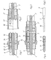
- a hybrid connector is shown in the general form of a socket.
- a round housing 1 which has the dimensions of the known M12 circular connector, has four openings extending in its longitudinal direction, of which only two, namely an opening 2 for receiving an optical waveguide and an opening 3 for receiving a copper line, are shown.
- the connector is provided in a manner not shown with two openings 2 and two openings 3, so that a variety of data connections to terminals (or sensors) can be produced, which can be powered via the two copper lines with power.
- electrical contact elements are inserted.
- ferrules such as the ferrule 4 are inserted.
- the contact elements and ferrules 4 are pressed into the housing 1, then enclosed with a sleeve which engages in the circumferential groove 12, and encapsulated with potting compound, so as to give the outer shape of the known M12 circular connector.
- a ferrule 4 is individually in Fig. 4 shown. It consists of a tube which is provided in an end region with an outer profile 5 and a flared end portion 6.
- the outer profile is used to fix the ferrule 4 in the housing 1, and the end portion 6 serves to receive an end portion 7 of the protective jacket 8 of an optical fiber vein 9, the Fig. 5 shows.
- This end region 7 is reduced in cross section with respect to the jacket 8.
- the optical waveguide 10 is received in the unexpanded part 11 of the ferrule 4.
- the jacket 8 is located outside the housing 1 in the prefabricated hybrid connector, while the end portion 7 is enclosed by the end portion 6.
- the optical waveguide 10 may be glued in the ferrule 4.
- Fig. 1 the ferrule 4 (with the inserted optical fiber) is pressed into the housing by tight fit.
- the housing 1 is provided approximately centrally with a collar 13, to which a housing section 14 connects to the right.
- a flexible sealing ring 15 is inserted, which rests on the collar 13.
- an optical sleeve 16 is further inserted, which partly surrounds the ferrule 4 and partly protrudes from the right end of the housing portion 14. This opto-sleeve is used for Reduction of the attenuation of the signals transmitted via the optical fibers to be connected.
- a hybrid connector in the general form of a connector is shown with the hybrid connector of Fig. 1 interacts.
- two openings 3 ' are provided for electrical contact elements for connecting copper lines and two openings 2' for the coupling of optical waveguides in a round housing 1 ', which as in the Fig. 1 is made.
- the openings 2 'ferrules 4' are again inserted, which are formed as the ferrules 4 and held by tight fit in the housing 1 '.
- the housing 1 ' has a sleeve-shaped, left end portion 17, which encloses a space 18. In this space 18, the ferrule 4 'protrudes into it and the housing portion 14 when mating the two hybrid connectors FIGS. 1, 2 recorded, like Fig. 3 shows.
- Fig. 3 is the ferrule 4 'inserted into the optical sleeve 4' so far that touch the two ferrules 4, 4 '(with the inserted optical fibers).
- the sealing ring 15 is deformed.
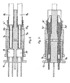
- FIGS. 6 to 9 two different versions for a hybrid connector are shown, in which in the first alternative case, the socket and in the second alternative case, the connector is to be arranged on a distributor, not shown.
- Special emphasis is placed on a simple coupling of the optical waveguide to the optical components (transmitter and receiver).
- This coupling is very simple in that the optical components are integrated in said socket or in said plug; both can do that Fiber optic each without spacers are contacted simultaneously.
- the contacting takes place simultaneously with the electrical contacts, which are designed in each case touch-safe.
- a jack 1 1 with two molded optical components (transmitter or receiver) 19, 20 provided, and in Fig. 7
- This socket 1 1 is provided with two molded socket contacts 3 1 , 3 2 for electrical conductors.
- Both components 19, 20 and both socket contacts 3 1 , 3 2 are at a distance from the central axis of the hybrid connector, and they are followed by openings that open on the right side of the socket 1 1 .
- Fig. 6 is also a plug 1 1 'provided with four distributed around the central axis of the hybrid connector longitudinal openings.
- two ferrules 4 1 , 4 2 potted, in the light guide 10 1 , 10 2 are introduced.
- the ferrules 4 1 , 4 2 have at their right ends extensions that receive the coats 8 1 , 8 2 of this light guide.
- the ferrules 4 1 , 4 2 are inserted with the light guides 10 1 , 10 2 to the components 19, 20.
- the plug 1 1 ' are also after Fig. 7 in the other two longitudinal openings two plug contacts 3 1 ', 3 2 ' cast, which are in contact with the socket contacts 3 1 , 3 2 .
- FIGS. 8 and 9 the socket and plug are reversed.
- Fig. 8 is a plug 1 2 'with two molded optical components (transmitter or receiver) 19, 20 provided
- Fig. 9 is this plug 1 2 'with two cast-in connector contacts 3 3 ', 3 4 'provided for electrical conductors.
- Both components 19, 20 and both plug contacts 3 3 ', 3 4 ' are at a distance from the center axis of the hybrid connector, and they are followed by openings that open on the right side of the plug 1 2 '.
- Fig. 8 is also a socket 1 2 provided with four distributed around the central axis of the hybrid connector longitudinal openings.
- two ferrules 4 1 , 4 2 potted, in the back light guide 10 1 10 2 are introduced.
- the ferrules 4 1 , 4 2 have extensions at their right ends, which again receive the sheaths 8 1 , 8 2 of these light guides.
- the ferrules 4 1 , 4 2 are inserted with the light guides 10 1 , 10 2 to the components 19, 20.
- the plug 1 1 ' are also after Fig. 9 in the other two longitudinal openings two socket contacts 3 3 , 3 4 poured, which are in contact with the plug contacts 3 3 ', 3 4 '.
Landscapes
- Physics & Mathematics (AREA)
- General Physics & Mathematics (AREA)
- Optics & Photonics (AREA)
- Mechanical Coupling Of Light Guides (AREA)
- Optical Couplings Of Light Guides (AREA)
Description
- Die Erfindung betrifft einen Hybridsteckverbinder gemäß dem Oberbegriff des Anspruchs 1.
- Ein derartiger Steckverbinder ist durch die
US-A-4 178 068 bekannt. Der Lichtwellenleiter ist mit einem querschnittsverengten Mantelteil im Steckergehäuse, und zwar in einer Crimphülse aufgenommen, die auch die Ferrule umschließt. Die Ferrule stütz sich dabei über eine Schraubenfeder an der Crimphülse bzw. an einer die Crimphülse umgebenden Sperrhülse ab. Der Aufbau dieses bekannten Hybridsteckverbinders ist für die Montage durch einen Benutzer geeignet. Von Nachteil ist jedoch, dass viele Einzelteile nötig sind, die das Risiko der Störanfälligkeit des Hybridsteckverbinders mit sich bringen, dass durch Aufnahme des Schutzmantels in das Steckergehäuse dieses einen verhältnismäßig großen Querschnitt haben muss und dass die für einen IP-Schutzgrad erforderliche Dichtheit gegen Fremdkörper und Feuchtigkeit und Beständigkeit gegen Chemikalien, wie Kühl- und Schmiermittel, nicht erreicht wird. - Durch die
DE-A1-19525210 ist eine Steckverbindung bekannt, die aus einem Stecker und einer Steckdose besteht, die mit einem Busankoppler eine Einheit bildet, und die zur optischen und elektrischen Verbindung dient. Der im Stecker mitgeführte Lichtleiter ist in diesem vergossen. Zur optischen Ankopplung dienen linsenartige Lichtleitererweiterungen, die über Fenster miteinander kommunizieren. Ferrule werden nicht verwendet. - Schließlich ist durch die
DE-A1-101 48 780 ein Hybridstecker mit optischer und elektrischer Verbindung bekannt, der eine zentrale Bohrung für den Lichtleiter aufweist, die von einer koaxialen, elektrischen Kontaktfläche umhüllt ist. Der Lichtleiter, der Kontakt und das Kabel werden nach der Montage im Steckergehäuse mittels einer Vergussmasse festgelegt. Eine Ferrule wird nicht verwendet. - Die genannte
US 4 178 068 und die genannteDE 101 48 780 gehen davon aus, dass die Lichtwellenleiter einzeln, ggf. noch zusammen mit einem einzelnen elektrischen Kontakt (DE 101 48 780 ), montiert und vergossen werden. Diese Einzelkontakte werden dann zu Steckverbindern zusammengestellt (US 4 178 068 ). - Die
US 4,767,181 zeigt einen Hybridsteckverbinder, bei dem ein Lichtwellenleiter und zwei elektrische Kontakte vom Material des Steckergehäuses umspritzt und so im Steckergehäuse gehalten sind. Die Fixierung der den Lichtwellenleiter teilweise umgebenden Hülse sowie des elektrischen Kontakts erfolgt dabei formschlüssig im Material des Gehäuses. - Die
EP 1 045 266 A2 zeigt einen Hybridsteckverbinder, bei dem der Lichtwellenleiter formschlüssig im Gehäuse gehalten ist. Auch hier ist der Lichtwellenleiter vom Material des Steckergehäuses umspritzt. - Die Aufgabe der Erfindung besteht darin, einen Hybridsteckverbinder der im Oberbegriff des Anspruchs 1 genannten Art zu schaffen, der einfach aufgebaut und damit weniger störanfällig ist und der im Durchmesser verhältnismäßig klein bleiben kann. Diese Aufgabe wird mit den Merkmalen des Anspruchs 1 gelöst.
- Üblicherweise werden Steckverbinder nach der Kontaktierung mit Kunststoff umspritzt. Durch die dabei auftretenden sehr hohen Temperaturen werden jedoch die optischen Polymerfasern der Lichtwellenleiter zerstört. Verhindert wird dies durch die Anwendung der Vergusstechnologie. Damit wird ein schonendes Umhüllen des Anschlussbereiches ermöglicht und gleichzeitig die hohen Anforderungen bezüglich Dichtheit, elektrischer Kennwerte und chemischer Beständigkeit erfüllt. Darüber hinaus werden die Lichtwellenleiter und elektrischen Leitungen lagerichtig im Gehäuse gehalten, so dass keine Federelemente zum Führen der Ferrulen benötigt werden. Mit der Vergusstechnologie gemäß der Erfindung gelingt es, alle Elemente in einem Gehäuse anzuordnen und dann gemeinsam zu vergießen. Dadurch kann auch eine kleine Bauform realisiert werden.
- Gemäß einer weiteren Ausbildung der Erfindung wird der Schutzmantel im Endbereich im Querschnitt verringert und dieser Endbereich in einer Ferrule aufgenommen. Damit kann eine verhältnismäßig dünne Ferrule verwendet werden. Beispielsweise kann nun für den Hybridsteckverbinder ein Gehäuse verwendet werden, das für die bekannten M12-Steckverbinder für die Verbindung von Kupferleitungen vorgesehen ist. Dabei ist der Lichtwellenleiter auch gegen das Eindringen von Fremdkörpern, Feuchtigkeit und Chemikalien geschützt.
- Um den genannten Mantelendbereich einfacher herzustellen, ist gemäß einer weiteren Ausbildung der Erfindung der Schutzmantel ein Doppelmantel und der äußere Mantel im genannten Endbereich entfernt.
- Gemäß einer weiteren Ausbildung der Erfindung sind die Lichtwellenleiter und die elektrischen Kontakte in einem definierten Raster um den zentrischen Mittelpunkt des Hybridsteckverbinders angeordnet. Dadurch kann auf das Absetzen des Schutzmantels im Endbereich gänzlich verzichtet werden; dafür ist das bekannte Steckbild des M12-Steckverbinders abzuändern, indem die Kontakte etwas nach außen gerückt werden. Die äußere Gestaltung des bekannten M12-Steckverbinders ändert sich hierdurch nicht. Daher ergibt sich gegenüber der genannten
DE 101 48 780 , bei der der einzige Lichtwellenleiter koaxial angeordnet ist, die Möglichkeit, unabhängig voneinander verschiedene Belegungen zu realisieren, beispielsweise zwei Lichtwellenleiter und zwei elektrische Leiter, aber auch jede andere Paarung. - Die Ferrulen sind derart gestaltet, dass sie einen Festsitz zum Einpressen in den Kontaktträger sowie einen geschlossenen Crimp zur Verbindung mit dem Kabelmantel besitzen.
- Gemäß einer weiteren Ausbildung der Erfindung wird zur Reduzierung der Dämpfung bei der Übertragung der optischen Signale im Steckverbinder eine Optohülse vorzugsweise aus Messing eingesetzt.
- Desweiteren können zur Ankopplung an die Sende- und Empfangselektronik in Fortführung der optischen Bauelemente optische Zwischenstücke erforderlich sein, die für eine verlustarme Übertragung der optischen Signale sorgen.
- Die Erfindung wird nun anhand von Ausführungsbeispielen näher erläutert. Es zeigen:
- Fig. 1
- einen Querschnitt durch einen Hybridsteckverbinder in Form einer Buchse gemäß der Erfindung,
- Fig. 2
- einen Querschnitt durch einen Hybridsteckverbinder in Form eines Steckers gemäß der Erfindung,
- Fig. 3
- einen Querschnitt durch die zusammengefügten Hybridsteckverbinder der
Figuren 1 und 2 , - Fig. 4
- einen Querschnitt durch eine beim Hybridsteckverbinder der
Fig. 1 - 3 verwendete Ferrule, - Fig. 5
- eine Seitenansicht eines Endabschnitts einer Ader des Lichtwellenleiters gemäß der Erfindung,
- Fig. 6
- einen Querschnitt durch eine zweite Ausführung einer Hybridsteckverbindung aus einer auf einem Verteiler anzuordnenden Buchse und einem in die Buchse gesteckten Stecker, wobei der Querschnitt die Kontaktierung der Lichtwellenleiter zeigt,
- Fig. 7
- einen der
Fig. 6 ähnlichen Querschnitt, der jedoch um 90° verdreht ist und die Kontaktierung der elektrischen Leiter zeigt, - Fig. 8
- einen Querschnitt durch eine dritte Ausführung einer Hybridsteckverbindung aus einer auf einem Verteiler anzuordnenden Stecker und einem auf den Stecker aufgesteckten Buchse, wobei der Querschnitt die Kontaktierung der Lichtwellenleiter zeigt, und
- Fig. 9
- einen der
Fig. 8 ähnlichen Querschnitt, der jedoch um 90° verdreht ist und die Kontaktierung der elektrischen Leiter zeigt. - In
Fig. 1 ist ein Hybridsteckverbinder in der allgemeinen Form einer Buchse dargestellt. Ein rundes Gehäuse 1, dass die Abmessungen des bekannten M12-Rundsteckverbinders aufweist, hat vier in seiner Längsrichtung verlaufende Öffnungen, von denen nur zwei, nämlich eine Öffnung 2 zur Aufnahme eines Lichtwellenleiters und eine Öffnung 3 zur Aufnahme einer Kupferleitung, gezeigt sind. Der Steckverbinder ist in nicht dargestellter Weise mit zwei Öffnungen 2 und zwei Öffnungen 3 versehen, so dass eine Vielzahl von Datenverbindungen zu Endgeräten (oder auch Sensoren) herstellbar ist, die über die beiden Kupferleitungen mit Strom versorgt werden können. In den Öffnungen 3 sind, wie nicht dargestellt ist, elektrische Kontaktelemente eingefügt. In den Öffnungen 2 sind so genannte Ferrulen, wie die Ferrule 4, eingelegt. Die Kontaktelemente und Ferrulen 4 werden in das Gehäuse 1 eingepresst, anschließend mit einer Hülse, die in die umlaufende Nut 12 eingreift, umschlossen und mit Vergussmasse vergossen, so dass sich die äußere Gestalt des bekannten M12-Rundsteckverbinders ergibt. - Eine Ferrule 4 ist einzeln in
Fig. 4 gezeigt. Sie besteht aus einem Rohr, das in einem Endbereich mit einem Außenprofil 5 und einem aufgeweiteten Endabschnitt 6 versehen ist. Das Außenprofil dient zur Festlegung der Ferrule 4 im Gehäuse 1, und der Endabschnitt 6 dient zur Aufnahme eines Endbereichs 7 des Schutzmantels 8 einer Lichtwellenleiter-Ader 9, den dieFig. 5 zeigt. Dieser Endbereich 7 ist im Querschnitt gegenüber dem Mantel 8 verringert. Der Lichtwellenleiter 10 wird im nicht aufgeweiteten Teil 11 der Ferrule 4 aufgenommen. Der Mantel 8 liegt beim konfektionierten Hybridsteckverbinder außerhalb des Gehäuses 1, während der Endbereich 7 von dem Endabschnitt 6 umschlossen ist. Der Lichtwellenleiter 10 kann in der Ferrule 4 eingeklebt sein. - In
Fig. 1 ist die Ferrule 4 (mit dem eingeführten Lichtwellenleiter) in das Gehäuse durch Festsitz eingedrückt. Das Gehäuse 1 ist etwa mittig mit einem Bund 13 versehen, an den sich nach rechts ein Gehäuseabschnitt 14 anschließt. Auf diesem Gehäuseabschnitt 14 ist ein flexibler Dichtungsring 15 eingelegt, der am Bund 13 anliegt. In die Öffnung 2 im Bereich des Gehäuseabschnitts 14 ist ferner eine Optohülse 16 eingelegt, die teils die Ferrule 4 umschließt und teils aus dem rechten Ende des Gehäuseabschnitts 14 hervorsteht. Diese Optohülse dient zur Verminderung der Dämpfung der Signale, die über die zu verbindenden Lichtwellenleiter übertragen werden. - In
Fig. 2 ist ein Hybridsteckverbinder in der allgemeinen Form eines Steckers dargestellt, der mit dem Hybridsteckverbinder derFig. 1 zusammenwirkt. In einer derFig. 1 ähnlichen Weise sind zwei Öffnungen 3' für elektrische Kontaktelemente zur Verbindung von Kupferleitungen und zwei Öffnungen 2' für die Koppelung von Lichtwellenleitern in einem runden Gehäuse 1' vorgesehen, das wie bei dem derFig. 1 hergestellt ist. In die Öffnungen 2' sind wieder Ferrulen 4' eingelegt, die wie die Ferrulen 4 ausgebildet und durch Festsitz im Gehäuse 1' gehalten werden. Das Gehäuse 1' hat einen hülsenförmigen, linken Endabschnitt 17, der einen Raum 18 umschließt. In diesen Raum 18 ragt die Ferrule 4' hinein und wird der Gehäuseabschnitt 14 beim Zusammenstecken der beiden Hybridsteckverbinder derFiguren 1, 2 aufgenommen, wieFig. 3 zeigt. - In
Fig. 3 ist die Ferrule 4' in die Optohülse 4' soweit eingeführt, dass sich die beiden Ferrulen 4, 4' (mit den eingelegten Lichtwellenleitern) berühren. Dabei wird der Dichtungsring 15 verformt. Durch den Dichtungsring 15 und die Vergusstechnik wird ein äußerst wirksamer Schutz gegen das Eindringen von Fremdkörpern, Feuchtigkeit und Chemikalien erreicht. - In den
Figuren 6 - 9 sind zwei verschiedene Ausführungen für eine Hybridsteckverbindung gezeigt, bei denen im ersten Alternativfall die Buchse und im zweiten Alternativfall der Stecker auf einem nicht dargestellten Verteiler anzuordnen ist. Besonderer Wert ist dabei auf eine einfache Ankopplung der Lichtwellenleiter an die optischen Bauelemente (Sender und Empfänger) gelegt. Diese Ankopplung ist sehr einfach gestaltet, indem die optischen Bauelemente mit in der genannten Buchse bzw. im genannten Stecker integriert sind; damit können beide Lichtwellenleiter jeweils ohne Zwischenstücke gleichzeitig kontaktiert werden. Die Kontaktierung erfolgt dabei gleichzeitig mit den elektrischen Kontakten, die jweils berührungssicher gestaltet sind. - Im Einzelnen ist der Aufbau der Hybridsteckverbindung im Prinzip wie in
Fig. 3 durchgeführt, mit dem Unterschied, dass Ferrulen nur im rechten Teil der Hybridsteckverbindung vorgesehen sind. - In
Fig. 6 ist eine Buchse 11 mit zwei eingegossenen, optischen Bauelementen (Sender bzw. Empfänger) 19, 20 versehen, und inFig. 7 ist diese Buchse 11 mit zwei eingegossenen Buchsenkontakten 31, 32 für elektrische Leiter versehen. Beide Bauelemente 19, 20 und beide Buchsenkontakte 31, 32 liegen in einem Abstand von der Mittelachse der Hybridsteckverbindung, und an sie schließen sich Öffnungen an, die auf der rechten Seite der Buchse 11 münden. - In
Fig. 6 ist auch ein Stecker 11' mit vier um die Mittelachse der Hybridsteckverbindung verteilten Längsöffnungen versehen. In zwei dieser Öffnungen sind zwei Ferrulen 41, 42 vergossen, in die Lichtleiter 101, 102 eingeführt sind. Die Ferrrulen 41, 42 weisen an ihren rechten Enden Erweiterungen auf, die die Mäntel 81, 82 dieser Lichtleiter aufnehmen. Die Ferrulen 41, 42 sind mit den Lichtleitern 101, 102 bis zu den Bauelementen 19, 20 eingesteckt. Im Stecker 11' sind auch nachFig. 7 in den anderen beiden Längsöffnungen zwei Steckerkontakten 31', 32' eingegossen, die mit den Buchsenkontakten 31, 32 in Kontakt stehen. - In den
Figuren 8 und 9 sind Buchse und Stecker vertauscht. InFig. 8 ist ein Stecker 12' mit zwei eingegossenen, optischen Bauelementen (Sender bzw. Empfänger) 19, 20 versehen, und inFig. 9 ist dieser Stecker 12' mit zwei eingegossenen Steckerkontakten 33', 34' für elektrische Leiter versehen. Beide Bauelemente 19, 20 und beide Steckerkontakte 33', 34' liegen in einem Abstand von der Mittelachse der Hybridsteckverbindung, und an sie schließen sich Öffnungen an, die auf der rechten Seite des Stecker 12' münden. - In
Fig. 8 ist auch eine Buchse 12 mit vier um die Mittelachse der Hybridsteckverbindung verteilten Längsöffnungen versehen. In zwei dieser Öffnungen sind zwei Ferrulen 41, 42 vergossen, in die wieder Lichtleiter 101 102 eingeführt sind. Die Ferrulen 41, 42 weisen an ihren rechten Enden Erweiterungen auf, die wieder die Mäntel 81, 82 dieser Lichtleiter aufnehmen. Die Ferrulen 41, 42 sind mit den Lichtleitern 101, 102 bis zu den Bauelementen 19, 20 eingesteckt. Im Stecker 11' sind auch nachFig. 9 in die anderen beiden Längsöffnungen zwei Buchsenkontakte 33, 34 eingegossen, die mit den Steckerkontakten 33', 34' in Kontakt stehen.
Claims (9)
- Hybridsteckverbinder mit einem für elektrische Steckverbinder vorgesehenen Gehäuse, in dem Kontaktelemente zum Anschluss von Kupferleitungen und Halteelemente zum Anschluss von Lichtwellenleitern befestigt sind, die jeweils mit einem Schutzmantel versehen sind, wobei die Halteelemente jeweils durch eine Ferrule gebildet sind, in der ein vom Schutzmantel befreiter Endabschnitt des Lichtwellenleiters festgelegt ist,
dadurch gekennzeichnet, dass die Ferrulen (4, 4') im Gehäuse (1,1') eingepresst sind und dass die Ferrulen (4, 4', 41 - 44), mehrere Lichtwellenleiter (2, 2') und mehrere elektrische Kontakte (3, 3', 31 - 34, 31' - 34') in einem gemeinsamen Gehäuse (1, 1', 11, 11', 12, 12') vergossen sind. - Hybridsteckverbinder nach Anspruch 1,
dadurch gekennzeichnet, dass die Ferrulen (4, 4') ohne zusätzliche Federelemente im Gehäuse (1, 1') eingesetzt werden. - Hybridsteckverbinder nach Anspruch 1 und 2,
dadurch gekennzeichnet, dass der Hybridsteckverbinder die äußere Gestalt des bekannten M12-Rundsteckverbinders aufweist. - Hybridsteckverbinder nach einem der Ansprüche 1 bis 3,
dadurch gekennzeichnet, dass der Schutzmantel (8) in einem Endbereich (7) im Querschnitt verringert und dieser Endbereich (7) in der Ferrule (4, 4') aufgenommen ist. - Hybridsteckverbinder nach einem der Ansprüche 1 bis 4,
dadurch gekennzeichnet, dass der Schutzmantel ein Doppelmantel und der äußere Mantel im genannten Endbereich entfernt ist. - Hybridsteckverbinder nach Anspruch 3,
dadurch gekennzeichnet, dass die Lichtwellenleiter (2, 2') und elektrischen Kontakte (3, 3') in einem definierten Raster um den zentrischen Mittelpunkt des Hybridsteckverbinders angeordnet sind. - Hybridsteckverbinder nach einem der Ansprüche 1 bis 6,
dadurch gekennzeichnet, dass die Ferrulen (4, 4') im hinteren Teil einen geschlossenen Crimp zur Verbindung mit dem Schutzmantel (7, 8) der Lichtwellenader (9) aufweisen. - Hybridsteckverbinder nach einem der Ansprüche 1 bis 7,
dadurch gekennzeichnet, dass im Gehäuse (1) eine Optohülse vorzugsweise aus Messing zur Reduzierung der Dämpfung angeordnet ist. - Hybridsteckverbinder nach einem der Ansprüche 1 bis 8,
dadurch gekennzeichnet, dass zur verbesserten Ankopplung an die Sende- und Empfangselektronik in Fortführung der optischen Bauelemente optische Zwischenstücke angeordnet sind.
Applications Claiming Priority (2)
| Application Number | Priority Date | Filing Date | Title |
|---|---|---|---|
| DE2003119418 DE10319418A1 (de) | 2003-04-29 | 2003-04-29 | Hybridsteckverbinder |
| PCT/EP2004/004186 WO2004097482A1 (de) | 2003-04-29 | 2004-04-21 | Hybridsteckverbinder |
Publications (2)
| Publication Number | Publication Date |
|---|---|
| EP1620758A1 EP1620758A1 (de) | 2006-02-01 |
| EP1620758B1 true EP1620758B1 (de) | 2014-12-10 |
Family
ID=33305045
Family Applications (1)
| Application Number | Title | Priority Date | Filing Date |
|---|---|---|---|
| EP04728527.5A Expired - Lifetime EP1620758B1 (de) | 2003-04-29 | 2004-04-21 | Hybridsteckverbinder |
Country Status (3)
| Country | Link |
|---|---|
| EP (1) | EP1620758B1 (de) |
| DE (1) | DE10319418A1 (de) |
| WO (1) | WO2004097482A1 (de) |
Families Citing this family (3)
| Publication number | Priority date | Publication date | Assignee | Title |
|---|---|---|---|---|
| DE102008050161B4 (de) * | 2008-10-01 | 2017-08-03 | Bayerische Motoren Werke Aktiengesellschaft | Hybrider Steckverbinder |
| WO2015120365A1 (en) | 2014-02-07 | 2015-08-13 | Tyco Electronics Corporation | Hardened optical power connection system |
| DE102024105480A1 (de) * | 2024-02-27 | 2025-08-28 | Hamilton Bonaduz Ag | Kombisensor und System zur Bestimmung des pH-Werts und des Sauerstoffgehalts einer Flüssigkeit |
Citations (2)
| Publication number | Priority date | Publication date | Assignee | Title |
|---|---|---|---|---|
| US4767181A (en) * | 1983-11-17 | 1988-08-30 | American Telephone And Telegraph Company | Electrical/lightwave connection arrangement |
| EP1045266A2 (de) * | 1999-04-13 | 2000-10-18 | Raczkowiak Kupferberg-Kabel GmbH | Gerätesteckdose für Datenbearbeitungsgeräte mit Lichtwellenleiteraustritt |
Family Cites Families (7)
| Publication number | Priority date | Publication date | Assignee | Title |
|---|---|---|---|---|
| US4178068A (en) * | 1977-11-14 | 1979-12-11 | Amp Incorporated | Fiber optic cable termination means |
| US4993803A (en) * | 1989-05-18 | 1991-02-19 | General Motors Corporation | Electro-optical header connector |
| DE59106807D1 (de) * | 1990-02-17 | 1995-12-07 | Stribel Gmbh | Signalübertragungsleitung. |
| DE19525210A1 (de) * | 1995-07-11 | 1997-01-16 | Merten Gmbh & Co Kg Geb | Elektrische Steckvorrichtung |
| DE10044790C1 (de) * | 2000-09-11 | 2002-04-04 | Contact Gmbh | Isolierkörper für einen Steckverbinder zur Übertragung optischer und elektrischer Signale |
| US6776652B2 (en) * | 2001-05-07 | 2004-08-17 | Autonetworks Technologies, Ltd. | Connector device and connector |
| DE10148780A1 (de) * | 2001-09-28 | 2003-04-10 | Zeiss Carl Jena Gmbh | Hybridstecker |
-
2003
- 2003-04-29 DE DE2003119418 patent/DE10319418A1/de not_active Withdrawn
-
2004
- 2004-04-21 WO PCT/EP2004/004186 patent/WO2004097482A1/de not_active Ceased
- 2004-04-21 EP EP04728527.5A patent/EP1620758B1/de not_active Expired - Lifetime
Patent Citations (2)
| Publication number | Priority date | Publication date | Assignee | Title |
|---|---|---|---|---|
| US4767181A (en) * | 1983-11-17 | 1988-08-30 | American Telephone And Telegraph Company | Electrical/lightwave connection arrangement |
| EP1045266A2 (de) * | 1999-04-13 | 2000-10-18 | Raczkowiak Kupferberg-Kabel GmbH | Gerätesteckdose für Datenbearbeitungsgeräte mit Lichtwellenleiteraustritt |
Also Published As
| Publication number | Publication date |
|---|---|
| WO2004097482A1 (de) | 2004-11-11 |
| EP1620758A1 (de) | 2006-02-01 |
| DE10319418A1 (de) | 2004-11-18 |
Similar Documents
| Publication | Publication Date | Title |
|---|---|---|
| EP3251173B1 (de) | Steckverbinderanordnung mit hülsenteil | |
| EP3251180B1 (de) | Steckverbinderanordnung mit kompensationshülse | |
| EP2417673B1 (de) | Elektrischer steckverbinder | |
| EP1783521B1 (de) | Steckverbinder und Steckkupplung in Form eines RJ45-Anschlusssystems | |
| DE4118096C2 (de) | ||
| DE202013006297U1 (de) | Steckverbinder | |
| DE69405679T2 (de) | Vorrichtung zur Sicherstellung der Kontinuität der elektrischen Abschirmung von Kabeln | |
| DE69216349T2 (de) | Kontaktvorrichtung für ein Kabel mit einem oder mehreren inneren Leitern | |
| DE2632535A1 (de) | Steckverbinderanordnung fuer lichtleitkabel | |
| DE19507669C2 (de) | Optischer Mehrfach-Steckverbinder, insbesondere für Rund- oder Zip-cord-Kabel | |
| EP4009452B1 (de) | Steckverbinderanordnung | |
| EP1936758B1 (de) | Steckverbinder mit Kontakten zur Übertragung von Signaldaten | |
| EP3467960B1 (de) | Elektrischer steckverbinder | |
| EP3837741B1 (de) | Kabelanordnung | |
| DE4102989C1 (en) | Water tight electric cable coupling - has annular insulator with seal between this and coupling inlet | |
| EP1467441A2 (de) | Schnellanschliessbare Steckverbindung in Spannzangentechnik | |
| DE10044790C1 (de) | Isolierkörper für einen Steckverbinder zur Übertragung optischer und elektrischer Signale | |
| EP3881750B1 (de) | Steckverbindung für ein videoendoskop, videoendoskop und verfahren zur herstellung einer steckverbindung | |
| DE3914978C2 (de) | Steckverbindung | |
| DE202006007028U1 (de) | Hochfrequenz-Anpassungsadapter | |
| EP3444907A1 (de) | Steckverbinderanordnung | |
| WO2004097482A1 (de) | Hybridsteckverbinder | |
| DE3137262C2 (de) | Elektrischer Steckverbinder für ein Zugentlastungsseil enthaltende Kabel | |
| DE69111939T2 (de) | Leitende Hülse zum Klemmen auf einen abgeschirmten elektrischen Steckverbinder. | |
| DE3042595A1 (de) | Aufschiebbare, mit geteiltem isolierkoerper versehene verbindungsmuffe fuer kunststoffisolierte mittelspannungskabel |
Legal Events
| Date | Code | Title | Description |
|---|---|---|---|
| PUAI | Public reference made under article 153(3) epc to a published international application that has entered the european phase |
Free format text: ORIGINAL CODE: 0009012 |
|
| 17P | Request for examination filed |
Effective date: 20051129 |
|
| AK | Designated contracting states |
Kind code of ref document: A1 Designated state(s): AT BE BG CH CY CZ DE DK EE ES FI FR GB GR HU IE IT LI LU MC NL PL PT RO SE SI SK TR |
|
| RAP1 | Party data changed (applicant data changed or rights of an application transferred) |
Owner name: MURR-ELEKTRONIK GESELLSCHAFT MIT BESCHRAENKTER HAF |
|
| DAX | Request for extension of the european patent (deleted) | ||
| 17Q | First examination report despatched |
Effective date: 20080408 |
|
| RAP1 | Party data changed (applicant data changed or rights of an application transferred) |
Owner name: MURRELEKTRONIK GMBH |
|
| GRAP | Despatch of communication of intention to grant a patent |
Free format text: ORIGINAL CODE: EPIDOSNIGR1 |
|
| RIC1 | Information provided on ipc code assigned before grant |
Ipc: G02B 6/38 20060101AFI20140707BHEP Ipc: G02B 6/42 20060101ALI20140707BHEP |
|
| INTG | Intention to grant announced |
Effective date: 20140725 |
|
| GRAS | Grant fee paid |
Free format text: ORIGINAL CODE: EPIDOSNIGR3 |
|
| GRAA | (expected) grant |
Free format text: ORIGINAL CODE: 0009210 |
|
| AK | Designated contracting states |
Kind code of ref document: B1 Designated state(s): AT BE BG CH CY CZ DE DK EE ES FI FR GB GR HU IE IT LI LU MC NL PL PT RO SE SI SK TR |
|
| REG | Reference to a national code |
Ref country code: GB Ref legal event code: FG4D Free format text: NOT ENGLISH |
|
| REG | Reference to a national code |
Ref country code: CH Ref legal event code: EP |
|
| REG | Reference to a national code |
Ref country code: IE Ref legal event code: FG4D Free format text: LANGUAGE OF EP DOCUMENT: GERMAN |
|
| REG | Reference to a national code |
Ref country code: AT Ref legal event code: REF Ref document number: 700928 Country of ref document: AT Kind code of ref document: T Effective date: 20150115 |
|
| REG | Reference to a national code |
Ref country code: DE Ref legal event code: R096 Ref document number: 502004014784 Country of ref document: DE Effective date: 20150122 |
|
| REG | Reference to a national code |
Ref country code: CH Ref legal event code: NV Representative=s name: ISLER AND PEDRAZZINI AG, CH |
|
| REG | Reference to a national code |
Ref country code: NL Ref legal event code: VDEP Effective date: 20141210 |
|
| REG | Reference to a national code |
Ref country code: FR Ref legal event code: PLFP Year of fee payment: 12 |
|
| REG | Reference to a national code |
Ref country code: NL Ref legal event code: VDEP Effective date: 20141210 |
|
| PG25 | Lapsed in a contracting state [announced via postgrant information from national office to epo] |
Ref country code: FI Free format text: LAPSE BECAUSE OF FAILURE TO SUBMIT A TRANSLATION OF THE DESCRIPTION OR TO PAY THE FEE WITHIN THE PRESCRIBED TIME-LIMIT Effective date: 20141210 Ref country code: ES Free format text: LAPSE BECAUSE OF FAILURE TO SUBMIT A TRANSLATION OF THE DESCRIPTION OR TO PAY THE FEE WITHIN THE PRESCRIBED TIME-LIMIT Effective date: 20141210 |
|
| PG25 | Lapsed in a contracting state [announced via postgrant information from national office to epo] |
Ref country code: GR Free format text: LAPSE BECAUSE OF FAILURE TO SUBMIT A TRANSLATION OF THE DESCRIPTION OR TO PAY THE FEE WITHIN THE PRESCRIBED TIME-LIMIT Effective date: 20150311 Ref country code: SE Free format text: LAPSE BECAUSE OF FAILURE TO SUBMIT A TRANSLATION OF THE DESCRIPTION OR TO PAY THE FEE WITHIN THE PRESCRIBED TIME-LIMIT Effective date: 20141210 |
|
| PG25 | Lapsed in a contracting state [announced via postgrant information from national office to epo] |
Ref country code: NL Free format text: LAPSE BECAUSE OF FAILURE TO SUBMIT A TRANSLATION OF THE DESCRIPTION OR TO PAY THE FEE WITHIN THE PRESCRIBED TIME-LIMIT Effective date: 20141210 |
|
| PG25 | Lapsed in a contracting state [announced via postgrant information from national office to epo] |
Ref country code: CZ Free format text: LAPSE BECAUSE OF FAILURE TO SUBMIT A TRANSLATION OF THE DESCRIPTION OR TO PAY THE FEE WITHIN THE PRESCRIBED TIME-LIMIT Effective date: 20141210 Ref country code: EE Free format text: LAPSE BECAUSE OF FAILURE TO SUBMIT A TRANSLATION OF THE DESCRIPTION OR TO PAY THE FEE WITHIN THE PRESCRIBED TIME-LIMIT Effective date: 20141210 Ref country code: SK Free format text: LAPSE BECAUSE OF FAILURE TO SUBMIT A TRANSLATION OF THE DESCRIPTION OR TO PAY THE FEE WITHIN THE PRESCRIBED TIME-LIMIT Effective date: 20141210 Ref country code: RO Free format text: LAPSE BECAUSE OF FAILURE TO SUBMIT A TRANSLATION OF THE DESCRIPTION OR TO PAY THE FEE WITHIN THE PRESCRIBED TIME-LIMIT Effective date: 20141210 Ref country code: PT Free format text: LAPSE BECAUSE OF FAILURE TO SUBMIT A TRANSLATION OF THE DESCRIPTION OR TO PAY THE FEE WITHIN THE PRESCRIBED TIME-LIMIT Effective date: 20150410 |
|
| PGFP | Annual fee paid to national office [announced via postgrant information from national office to epo] |
Ref country code: CH Payment date: 20150420 Year of fee payment: 12 Ref country code: GB Payment date: 20150420 Year of fee payment: 12 |
|
| PG25 | Lapsed in a contracting state [announced via postgrant information from national office to epo] |
Ref country code: PL Free format text: LAPSE BECAUSE OF FAILURE TO SUBMIT A TRANSLATION OF THE DESCRIPTION OR TO PAY THE FEE WITHIN THE PRESCRIBED TIME-LIMIT Effective date: 20141210 |
|
| PGFP | Annual fee paid to national office [announced via postgrant information from national office to epo] |
Ref country code: FR Payment date: 20150421 Year of fee payment: 12 Ref country code: IT Payment date: 20150429 Year of fee payment: 12 |
|
| REG | Reference to a national code |
Ref country code: DE Ref legal event code: R097 Ref document number: 502004014784 Country of ref document: DE |
|
| PLBE | No opposition filed within time limit |
Free format text: ORIGINAL CODE: 0009261 |
|
| STAA | Information on the status of an ep patent application or granted ep patent |
Free format text: STATUS: NO OPPOSITION FILED WITHIN TIME LIMIT |
|
| PG25 | Lapsed in a contracting state [announced via postgrant information from national office to epo] |
Ref country code: DK Free format text: LAPSE BECAUSE OF FAILURE TO SUBMIT A TRANSLATION OF THE DESCRIPTION OR TO PAY THE FEE WITHIN THE PRESCRIBED TIME-LIMIT Effective date: 20141210 |
|
| 26N | No opposition filed |
Effective date: 20150911 |
|
| PG25 | Lapsed in a contracting state [announced via postgrant information from national office to epo] |
Ref country code: LU Free format text: LAPSE BECAUSE OF FAILURE TO SUBMIT A TRANSLATION OF THE DESCRIPTION OR TO PAY THE FEE WITHIN THE PRESCRIBED TIME-LIMIT Effective date: 20150421 Ref country code: MC Free format text: LAPSE BECAUSE OF FAILURE TO SUBMIT A TRANSLATION OF THE DESCRIPTION OR TO PAY THE FEE WITHIN THE PRESCRIBED TIME-LIMIT Effective date: 20141210 |
|
| REG | Reference to a national code |
Ref country code: IE Ref legal event code: MM4A |
|
| PG25 | Lapsed in a contracting state [announced via postgrant information from national office to epo] |
Ref country code: SI Free format text: LAPSE BECAUSE OF FAILURE TO SUBMIT A TRANSLATION OF THE DESCRIPTION OR TO PAY THE FEE WITHIN THE PRESCRIBED TIME-LIMIT Effective date: 20141210 |
|
| PG25 | Lapsed in a contracting state [announced via postgrant information from national office to epo] |
Ref country code: IE Free format text: LAPSE BECAUSE OF NON-PAYMENT OF DUE FEES Effective date: 20150421 |
|
| REG | Reference to a national code |
Ref country code: AT Ref legal event code: MM01 Ref document number: 700928 Country of ref document: AT Kind code of ref document: T Effective date: 20150421 |
|
| PG25 | Lapsed in a contracting state [announced via postgrant information from national office to epo] |
Ref country code: AT Free format text: LAPSE BECAUSE OF NON-PAYMENT OF DUE FEES Effective date: 20150421 |
|
| REG | Reference to a national code |
Ref country code: CH Ref legal event code: PL |
|
| GBPC | Gb: european patent ceased through non-payment of renewal fee |
Effective date: 20160421 |
|
| REG | Reference to a national code |
Ref country code: FR Ref legal event code: ST Effective date: 20161230 |
|
| PG25 | Lapsed in a contracting state [announced via postgrant information from national office to epo] |
Ref country code: CH Free format text: LAPSE BECAUSE OF NON-PAYMENT OF DUE FEES Effective date: 20160430 Ref country code: LI Free format text: LAPSE BECAUSE OF NON-PAYMENT OF DUE FEES Effective date: 20160430 Ref country code: GB Free format text: LAPSE BECAUSE OF NON-PAYMENT OF DUE FEES Effective date: 20160421 Ref country code: FR Free format text: LAPSE BECAUSE OF NON-PAYMENT OF DUE FEES Effective date: 20160502 |
|
| PG25 | Lapsed in a contracting state [announced via postgrant information from national office to epo] |
Ref country code: IT Free format text: LAPSE BECAUSE OF NON-PAYMENT OF DUE FEES Effective date: 20160421 |
|
| PG25 | Lapsed in a contracting state [announced via postgrant information from national office to epo] |
Ref country code: BG Free format text: LAPSE BECAUSE OF FAILURE TO SUBMIT A TRANSLATION OF THE DESCRIPTION OR TO PAY THE FEE WITHIN THE PRESCRIBED TIME-LIMIT Effective date: 20141210 Ref country code: HU Free format text: LAPSE BECAUSE OF FAILURE TO SUBMIT A TRANSLATION OF THE DESCRIPTION OR TO PAY THE FEE WITHIN THE PRESCRIBED TIME-LIMIT; INVALID AB INITIO Effective date: 20040421 |
|
| PG25 | Lapsed in a contracting state [announced via postgrant information from national office to epo] |
Ref country code: CY Free format text: LAPSE BECAUSE OF FAILURE TO SUBMIT A TRANSLATION OF THE DESCRIPTION OR TO PAY THE FEE WITHIN THE PRESCRIBED TIME-LIMIT Effective date: 20141210 |
|
| PG25 | Lapsed in a contracting state [announced via postgrant information from national office to epo] |
Ref country code: BE Free format text: LAPSE BECAUSE OF NON-PAYMENT OF DUE FEES Effective date: 20150430 |
|
| PG25 | Lapsed in a contracting state [announced via postgrant information from national office to epo] |
Ref country code: TR Free format text: LAPSE BECAUSE OF FAILURE TO SUBMIT A TRANSLATION OF THE DESCRIPTION OR TO PAY THE FEE WITHIN THE PRESCRIBED TIME-LIMIT Effective date: 20141210 |
|
| PGFP | Annual fee paid to national office [announced via postgrant information from national office to epo] |
Ref country code: DE Payment date: 20200420 Year of fee payment: 17 |
|
| REG | Reference to a national code |
Ref country code: DE Ref legal event code: R119 Ref document number: 502004014784 Country of ref document: DE |
|
| PG25 | Lapsed in a contracting state [announced via postgrant information from national office to epo] |
Ref country code: DE Free format text: LAPSE BECAUSE OF NON-PAYMENT OF DUE FEES Effective date: 20211103 |