EP1620688B1 - Procede et appareil de collecte de vapeur - Google Patents
Procede et appareil de collecte de vapeur Download PDFInfo
- Publication number
- EP1620688B1 EP1620688B1 EP04718575A EP04718575A EP1620688B1 EP 1620688 B1 EP1620688 B1 EP 1620688B1 EP 04718575 A EP04718575 A EP 04718575A EP 04718575 A EP04718575 A EP 04718575A EP 1620688 B1 EP1620688 B1 EP 1620688B1
- Authority
- EP
- European Patent Office
- Prior art keywords
- gap
- chamber
- gas
- substrate
- control
- Prior art date
- Legal status (The legal status is an assumption and is not a legal conclusion. Google has not performed a legal analysis and makes no representation as to the accuracy of the status listed.)
- Expired - Lifetime
Links
- 238000000034 method Methods 0.000 title claims abstract description 48
- 239000000758 substrate Substances 0.000 claims abstract description 48
- 238000010790 dilution Methods 0.000 claims abstract description 39
- 239000012895 dilution Substances 0.000 claims abstract description 39
- 239000007789 gas Substances 0.000 claims description 149
- 239000011261 inert gas Substances 0.000 claims description 11
- 230000001939 inductive effect Effects 0.000 claims description 5
- 239000000463 material Substances 0.000 description 127
- 239000012071 phase Substances 0.000 description 85
- 238000001035 drying Methods 0.000 description 32
- 238000000926 separation method Methods 0.000 description 21
- 239000000203 mixture Substances 0.000 description 18
- 239000002904 solvent Substances 0.000 description 17
- 239000003570 air Substances 0.000 description 16
- 230000007246 mechanism Effects 0.000 description 16
- 238000010438 heat treatment Methods 0.000 description 13
- 238000009833 condensation Methods 0.000 description 12
- 230000005494 condensation Effects 0.000 description 12
- 238000000576 coating method Methods 0.000 description 11
- 238000007789 sealing Methods 0.000 description 11
- 238000012545 processing Methods 0.000 description 10
- 239000011248 coating agent Substances 0.000 description 9
- XLYOFNOQVPJJNP-UHFFFAOYSA-N water Substances O XLYOFNOQVPJJNP-UHFFFAOYSA-N 0.000 description 7
- YXFVVABEGXRONW-UHFFFAOYSA-N Toluene Chemical compound CC1=CC=CC=C1 YXFVVABEGXRONW-UHFFFAOYSA-N 0.000 description 6
- 238000001704 evaporation Methods 0.000 description 6
- 238000001179 sorption measurement Methods 0.000 description 6
- 230000008020 evaporation Effects 0.000 description 5
- 230000008569 process Effects 0.000 description 5
- 238000011084 recovery Methods 0.000 description 5
- 238000012546 transfer Methods 0.000 description 5
- OKTJSMMVPCPJKN-UHFFFAOYSA-N Carbon Chemical compound [C] OKTJSMMVPCPJKN-UHFFFAOYSA-N 0.000 description 4
- LFQSCWFLJHTTHZ-UHFFFAOYSA-N Ethanol Chemical compound CCO LFQSCWFLJHTTHZ-UHFFFAOYSA-N 0.000 description 4
- 238000010521 absorption reaction Methods 0.000 description 4
- 230000008901 benefit Effects 0.000 description 4
- 230000009467 reduction Effects 0.000 description 4
- 230000002411 adverse Effects 0.000 description 3
- 238000011109 contamination Methods 0.000 description 3
- 230000006378 damage Effects 0.000 description 3
- 239000012530 fluid Substances 0.000 description 3
- 239000007788 liquid Substances 0.000 description 3
- 239000007791 liquid phase Substances 0.000 description 3
- 238000005259 measurement Methods 0.000 description 3
- 239000003960 organic solvent Substances 0.000 description 3
- 239000000243 solution Substances 0.000 description 3
- 239000012808 vapor phase Substances 0.000 description 3
- IJGRMHOSHXDMSA-UHFFFAOYSA-N Atomic nitrogen Chemical compound N#N IJGRMHOSHXDMSA-UHFFFAOYSA-N 0.000 description 2
- CURLTUGMZLYLDI-UHFFFAOYSA-N Carbon dioxide Chemical compound O=C=O CURLTUGMZLYLDI-UHFFFAOYSA-N 0.000 description 2
- 239000011358 absorbing material Substances 0.000 description 2
- 239000012080 ambient air Substances 0.000 description 2
- QVGXLLKOCUKJST-UHFFFAOYSA-N atomic oxygen Chemical compound [O] QVGXLLKOCUKJST-UHFFFAOYSA-N 0.000 description 2
- 238000006243 chemical reaction Methods 0.000 description 2
- 238000004891 communication Methods 0.000 description 2
- 230000000052 comparative effect Effects 0.000 description 2
- 230000007613 environmental effect Effects 0.000 description 2
- 230000036541 health Effects 0.000 description 2
- 230000006872 improvement Effects 0.000 description 2
- 229910010272 inorganic material Inorganic materials 0.000 description 2
- 239000012528 membrane Substances 0.000 description 2
- 239000001301 oxygen Substances 0.000 description 2
- 229910052760 oxygen Inorganic materials 0.000 description 2
- 239000013618 particulate matter Substances 0.000 description 2
- 229920000728 polyester Polymers 0.000 description 2
- 229920006267 polyester film Polymers 0.000 description 2
- -1 preferably a clean Substances 0.000 description 2
- 239000007790 solid phase Substances 0.000 description 2
- 229910001220 stainless steel Inorganic materials 0.000 description 2
- 239000010935 stainless steel Substances 0.000 description 2
- 230000008016 vaporization Effects 0.000 description 2
- 208000034804 Product quality issues Diseases 0.000 description 1
- XAGFODPZIPBFFR-UHFFFAOYSA-N aluminium Chemical compound [Al] XAGFODPZIPBFFR-UHFFFAOYSA-N 0.000 description 1
- 229910052782 aluminium Inorganic materials 0.000 description 1
- 230000015572 biosynthetic process Effects 0.000 description 1
- 239000001569 carbon dioxide Substances 0.000 description 1
- 229910002092 carbon dioxide Inorganic materials 0.000 description 1
- 239000000969 carrier Substances 0.000 description 1
- 239000000919 ceramic Substances 0.000 description 1
- 230000008859 change Effects 0.000 description 1
- 230000003749 cleanliness Effects 0.000 description 1
- 238000002485 combustion reaction Methods 0.000 description 1
- 239000000356 contaminant Substances 0.000 description 1
- 238000007796 conventional method Methods 0.000 description 1
- 230000007547 defect Effects 0.000 description 1
- 230000001419 dependent effect Effects 0.000 description 1
- 230000008021 deposition Effects 0.000 description 1
- 238000013461 design Methods 0.000 description 1
- 238000007865 diluting Methods 0.000 description 1
- 239000006185 dispersion Substances 0.000 description 1
- 230000005611 electricity Effects 0.000 description 1
- 230000005670 electromagnetic radiation Effects 0.000 description 1
- 239000000839 emulsion Substances 0.000 description 1
- 238000004880 explosion Methods 0.000 description 1
- 239000000835 fiber Substances 0.000 description 1
- 235000013305 food Nutrition 0.000 description 1
- 239000000446 fuel Substances 0.000 description 1
- 230000006870 function Effects 0.000 description 1
- 230000004941 influx Effects 0.000 description 1
- 150000002484 inorganic compounds Chemical class 0.000 description 1
- 239000011147 inorganic material Substances 0.000 description 1
- 229910001867 inorganic solvent Inorganic materials 0.000 description 1
- 239000003049 inorganic solvent Substances 0.000 description 1
- 238000007689 inspection Methods 0.000 description 1
- 238000009434 installation Methods 0.000 description 1
- 238000004519 manufacturing process Methods 0.000 description 1
- 238000013206 minimal dilution Methods 0.000 description 1
- 238000012986 modification Methods 0.000 description 1
- 230000004048 modification Effects 0.000 description 1
- 229910052757 nitrogen Inorganic materials 0.000 description 1
- 239000004745 nonwoven fabric Substances 0.000 description 1
- 150000002894 organic compounds Chemical class 0.000 description 1
- 239000000123 paper Substances 0.000 description 1
- 239000006072 paste Substances 0.000 description 1
- 239000000825 pharmaceutical preparation Substances 0.000 description 1
- 229940127557 pharmaceutical product Drugs 0.000 description 1
- 239000000049 pigment Substances 0.000 description 1
- 239000002985 plastic film Substances 0.000 description 1
- 229920006255 plastic film Polymers 0.000 description 1
- 229920000642 polymer Polymers 0.000 description 1
- 239000011148 porous material Substances 0.000 description 1
- 239000000843 powder Substances 0.000 description 1
- 238000010926 purge Methods 0.000 description 1
- 230000005855 radiation Effects 0.000 description 1
- 229920006395 saturated elastomer Polymers 0.000 description 1
- 238000006748 scratching Methods 0.000 description 1
- 230000002393 scratching effect Effects 0.000 description 1
- 239000008247 solid mixture Substances 0.000 description 1
- 230000003068 static effect Effects 0.000 description 1
- 229920003048 styrene butadiene rubber Polymers 0.000 description 1
- 238000006467 substitution reaction Methods 0.000 description 1
- 238000009834 vaporization Methods 0.000 description 1
- 125000000391 vinyl group Chemical group [H]C([*])=C([H])[H] 0.000 description 1
- 229920002554 vinyl polymer Polymers 0.000 description 1
- 230000004580 weight loss Effects 0.000 description 1
Images

Classifications
-
- F—MECHANICAL ENGINEERING; LIGHTING; HEATING; WEAPONS; BLASTING
- F26—DRYING
- F26B—DRYING SOLID MATERIALS OR OBJECTS BY REMOVING LIQUID THEREFROM
- F26B13/00—Machines and apparatus for drying fabrics, fibres, yarns, or other materials in long lengths, with progressive movement
-
- F—MECHANICAL ENGINEERING; LIGHTING; HEATING; WEAPONS; BLASTING
- F26—DRYING
- F26B—DRYING SOLID MATERIALS OR OBJECTS BY REMOVING LIQUID THEREFROM
- F26B13/00—Machines and apparatus for drying fabrics, fibres, yarns, or other materials in long lengths, with progressive movement
- F26B13/10—Arrangements for feeding, heating or supporting materials; Controlling movement, tension or position of materials
-
- F—MECHANICAL ENGINEERING; LIGHTING; HEATING; WEAPONS; BLASTING
- F26—DRYING
- F26B—DRYING SOLID MATERIALS OR OBJECTS BY REMOVING LIQUID THEREFROM
- F26B13/00—Machines and apparatus for drying fabrics, fibres, yarns, or other materials in long lengths, with progressive movement
- F26B13/005—Seals, locks, e.g. gas barriers for web drying enclosures
-
- F—MECHANICAL ENGINEERING; LIGHTING; HEATING; WEAPONS; BLASTING
- F26—DRYING
- F26B—DRYING SOLID MATERIALS OR OBJECTS BY REMOVING LIQUID THEREFROM
- F26B25/00—Details of general application not covered by group F26B21/00 or F26B23/00
-
- F—MECHANICAL ENGINEERING; LIGHTING; HEATING; WEAPONS; BLASTING
- F26—DRYING
- F26B—DRYING SOLID MATERIALS OR OBJECTS BY REMOVING LIQUID THEREFROM
- F26B25/00—Details of general application not covered by group F26B21/00 or F26B23/00
- F26B25/005—Treatment of dryer exhaust gases
- F26B25/006—Separating volatiles, e.g. recovering solvents from dryer exhaust gases
Definitions
- the present invention relates to a vapor collection method, and more particularly to a method that enables the collection of gas phase components without substantial dilution.
- thermodynamics associated with the conventional vapor collection systems often permit undesirable condensation of the vapor at or near the substrate or material.
- the condensate can then fall onto the substrate or material and adversely affect either the appearance or functional aspects of the material.
- the ambient conditions surrounding the process and processing equipment may include extraneous matter.
- the extraneous matter may be drawn into the collection system by the large volumetric flows of the conventional drying systems.
- WO 02/25193 refers to a vapor collection method and apparatus capable of capturing vapor compositions without substantial dilution.
- gas is removed at a particular port using a pressure gradient while maintaining low volumetric flows within the device.
- US 4,894,927 refers to a closed vapor collection system with an oven for drying photographic emulsions. A heated inert gas stream is blown through the oven past heaters which are located above and below a moving web.
- the present invention provides a method and apparatus for transporting and capturing gas phase components without substantial dilution.
- the method and apparatus utilize a chamber in close proximity to the surface of a substrate to enable collection of gas phase components near the surface of the substrate.
- At least one material is provided that has at least one major surface with an adjacent gas phase.
- a chamber is then positioned in close proximity to the surface of the material to define a gap between the chamber and the material.
- the gap is preferably no greater than 3 cm.
- the adjacent gas phase between the chamber and the surface of the material defines a region possessing an amount of mass. At least a portion of the mass from the adjacent gas phase is transported through the chamber by inducing a flow through the region.
- M1 is the total net time-average mass flow per unit width through the gap into the region and through the chamber resulting from pressure gradients
- M2 is the time-average mass flow per unit width from the at least one major surface of the material into said region and through the chamber
- M3 is the total net time-average mass flow per unit width through the gap into the region and through the chamber resulting from motion of the material
- M4 is the time-average rate of mass transported per unit width through the chamber.
- the dimensions defining the width is the length of the gap in the direction perpendicular to the motion of the material and in the plane of the material.
- the present method and apparatus is designed to substantially reduce the amount of dilution gas transported through the chamber.
- the use of a chamber in close proximity to the surface of the material and small negative pressure gradients enables the substantial reduction of dilution gas, namely M1.
- the value of M1 is generally greater than zero but not greater than 0.25 kg/second/meter.
- M1 is greater than zero but not greater than 0.1 kg/second/meter, and most preferably, greater than zero but not greater than 0.01 kg/second/meter.
- the average velocity resulting from M1 may be utilized to express the flow of dilution gas phase components entering the chamber.
- the use of a chamber in close proximity to the surface of the material, and small negative pressure gradients, enables the substantial reduction of the average total net gas phase velocity, ⁇ v>, through the gap.
- the value of ⁇ v> is generally greater than zero but not greater than 0.5 meters/second.
- the present method attempts to significantly reduce dilution of the gas phase component in the adjacent gas phase by substantially reducing M1 in Equation 1.
- M1 represents the total net gas phase dilution flow per unit width into the region caused by a pressure gradient.
- the dilution of the mass in the adjacent gas phase may adversely affect the efficiency of gas phase collection systems and subsequent separation practices.
- M 1 is greater than zero but no greater than 0.25 kg/second/meter.
- the average velocity of gas phase components through the gap caused by induced flow is generally no greater than 0.5 meters/second.
- the present invention may be considered as an apparatus for treating a moving substrate of indefinite length.
- This apparatus will have a control surface in close proximity to a surface of the substrate to define a control gap between the substrate and the control surface.
- a first chamber is positioned near the control surface, with the first chamber having a gas introduction device.
- a second chamber is positioned near the control surface, the second chamber having a gas withdrawal device.
- the control surface and the chambers together define a region wherein the adjacent gas phases possess an amount of mass. Upon inducement of at least a portion of the mass within the region, the mass flow is segmented into the following components:
- the apparatus of the present invention preferably limits M1 to an absolute value not greater than 0.25 kg/second/meter.
- the dilution of the mass in the adjacent gas phase may adversely affect the system.
- Other disadvantages of the M1 flow will make themselves apparent.
- the M1 flow could contain a particulate matter and other airborne contaminants. It generally possesses an uncontrolled composition, is of an uncontrolled temperature, and uncontrolled relative humidity.
- M1' it is desirable to reduce dilution of the gas phase component in the adjacent gas phase by substantially controlling M1' and M4.
- a deliberate influx of a gas preferably a clean, inert gas with a controlled humidity
- M1' can accomplish much to provide a clean, controlled environment for the material without increasing dilution unduly.
- a gas preferably a clean, inert gas with a controlled humidity
- M1' can accomplish much to provide a clean, controlled environment for the material without increasing dilution unduly.
- Those skilled in the art will readily be able to select the composition; temperature, and humidity of gaseous environment that is appropriate for a particular desired application.
- flow M1 can be significantly curtailed by the creation of a slight positive pressure in the region.
- M1 is a signed number, positive when it represents a small inflow into the region, negative when it represents a small outflow from the region.
- the absolute value of M1 is preferably held to less than 0.25 kg/second/meter, and most preferably less than 0.025 kg/second/meter.
- the present invention can be thought out as a method for treating a moving substrate of indefinite length, comprising:
- Organic and inorganic solvents are examples of components that are often utilized as carriers to permit the deposition of a desired composition onto a substrate or material.
- the components are generally removed from the substrate or material by supplying a sufficient amount of energy to permit the vaporization of the solvent. It is desirable, and often necessary for health, safety, and environmental reasons, to recover the vaporous components after they have been removed from the substrate or material.
- the present invention is capable of collecting and transporting vapor components without introducing a substantial volume of a dilution stream.
- the method of the present invention includes the use of material that contains at least one evaporative component.
- the chamber is positioned in close proximity to a surface of the material. Sufficient energy is then directed at the material to vaporize the at least one evaporative component to form a vapor component. At least a portion of the vapor component is captured in the chamber.
- the vapor component is generally captured at a high concentration that allows subsequent processing, such as separation, to become more efficient.
- the apparatus of the present invention includes a support mechanism for supporting material.
- the material has at least one major surface with an adjacent gas phase.
- a chamber is placed in close proximity to the surface of the material to define a gap between the surface and the collection chamber.
- the adjacent gas phase between the chamber and the material defines a region containing an amount of mass.
- a mechanism in communication with the chamber induces the transport of at least a portion of the mass in the adjacent gas phase through the region.
- the transport of mass through the region into the chamber is represented by Equation I.
- the vapor in the chamber may optionally be conveyed to a separating mechanism for additional processing.
- the method and apparatus of the present invention are preferably suited for use in transporting and collecting solvents from a moving web.
- the chamber is placed above the continuously moving web to collect vapors at a high concentration.
- the low volumetric flows and high concentrations of the vapor improve the efficiency of the solvent recovery and substantially eliminate contamination problems associated with conventional component collection devices.
- Gap drying systems generally convey a material through a narrow gap between hot plate and a condensing plate for the evaporation and subsequent condensation of evaporative components in the material.
- the configuration of the present apparatus in various locations of a gap drying system, enables further capture of gas phase components which generally can be present in the adjacent gas phase on the surface of the material either prior to entering, or exiting a gap drying unit.
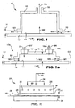
- the method and apparatus 10 of the present invention are generally described in FIG. 1 .
- the method includes providing a material 12 having at least one major surface 14 with an adjacent gas phase (not shown).
- a chamber 16, having an exhaust port 18 is positioned in close proximity to define a gap between the lower periphery 19 of the chamber 16 and the surface 14 of the material 12.
- the gap has a height H, which is preferably 3 cm or less.
- the adjacent gas phase between the lower periphery 19 of the chamber 16 and the surface 14 of the material 12 define a region possessing an amount of mass.
- the mass in the region is generally in a gas phase. However, those skilled in the art recognize that the region may also contain mass that is in either the liquid or solid phase, or combinations of all three phases.
- FIG. 1 and FIG. 1a depict the various flow streams encountered in practicing the method of the present invention.
- M1 is the total net time-average mass flow per unit width through the gap into the region and through the chamber resulting from pressure gradients.
- M1 essentially represents a dilution stream.
- M2 is the time-average mass flow per unit width from the at least one major surface of the material into said region and through the chamber.
- M3 is the total net time-average mass flow per unit width through the gap into the region and through the chamber resulting from motion of the material. M3 is generally recognized as mechanical drag and covers both the mass pulled in by the motion of the material under the chamber and the mass exiting from underneath the chamber as the material passes. In cases where the material is static under the chamber, M3 would be zero. In case where the gap H is uniform (i.e., the gap at the entrance and exit of the chamber are equal) M3 is zero. M3 is non-zero when the entrance and exit gaps are non uniform (i.e., not equal). M4 is the time-average rate of mass transported per unit width through the chamber. It is understood that mass can be transported through the gap and into the region without being transported through the chamber. Such flows are not included in the total net flows included in Equation 1. For purposes of the invention the dimension defining the width is the length of the gap in the direction perpendicular to the motion of the material and in the plane of the material.
- the present method and apparatus is designed to substantially reduce the amount of dilution gas transported through the chamber.
- the use of a chamber in close proximity to the surface of the material and extremely small negative pressure gradients enables the substantial reduction of dilution gas, namely M1.
- the value of M1 is generally greater than zero but not greater than 0.25 kg/second/meter.
- M1 is greater than zero but not greater than 0.1 kg/second/meter, and most preferably, greater than zero but not greater than 0.01 kg/second/meter.
- the average velocity resulting from M1 may be utilized to express the flow to dilution gas phase components through the chamber.
- M1 is defined above, ⁇ is the average gas stream density in kg/cubic meter and A is the cross sectional area per unit width available for flow into the region in meters.
- A (H(2w+2l))/w
- H is defined above
- w is the length of the gap in the direction perpendicular to the motion of the material
- 1 is the length of the gap in the direction of material motion.
- ⁇ v> is generally greater than zero but not greater than 0.5 meters/second.
- the close proximity of the chamber to the surface, and the relatively small pressure gradient, enable the transport of the mass in the adjacent gas phase through the chamber with minimal dilution. Thus lower flow rates at higher concentrations may be transported and collected.
- the present method is also suitable for transporting and collecting relatively small amounts of mass located in the adjacent gas phase.
- the gap height is generally 3 cm or less, preferably 1.5 cm or less, and most preferably 0.75 cm or less. Additionally, in a preferred embodiments, the gap is substantially uniform around the periphery of the chamber. However, the gap may be varied, or non-uniform for specific applications.
- the chamber may have a periphery wider than the material, or web conveyed under the chamber.
- the chamber can be designed to seal the sides to further reduce time-average mass flow per unit width from pressure gradients (M1).
- the chamber can also be designed to conform to different geometry material surfaces.
- the chamber can have a radiused lower periphery to conform to the surface of a cylinder.
- the material utilized may include any material that is capable of being positioned in close proximity to the chamber.
- the preferred material is a web.
- the web may include one or more layers of material or coatings applied onto a substrate.
- apparatus 10a also includes providing a substrate 12 having at least one major surface 14 with an adjacent gas phase (not shown).
- the substrate 12 is in motion in the direction of arrow "V" under a control surface 15, thus defining a control gap "G".
- a first chamber 17 having a gas introduction device 21 is positioned near the control surface 15.
- the exact form of the gas introduction device 21 may vary, and expedients such as a gas knife, a gas curtain, or a gas manifold can be used. While the illustrated embodiment depicts first chamber 17 in the form of a plenum, it is not a requirement of the invention that the gas introduction device 21 be positioned at a remove from the level of control surface 15. A second chamber 16a is also positioned near the control surface 15, and has a gas withdrawal device 18a. Once again, while the illustrated embodiment depicts the second chamber 16a in the form of a plenum, it is not a requirement of the invention that the gas withdrawal device 18a be positioned at the level of control surface 15. In most preferred embodiments, the first chamber 17 and the second chamber 16a will be at opposing ends of the control surface 15 as depicted in Figure 1a .
- the first chamber 17 defines a first gap G1 between the first chamber 17 and the substrate 12.
- the second chamber 16a defines a second gap G2 between the second chamber 16a and the substrate 12.
- the first gap G1, the second gap G2, and the control gap G are all of equal height, however in some other preferred embodiments, at least one of the first gap G 1 or the second gap G2 has a height different than the control gap G. Best results are achieved when the first gap, the second gap, and the control gap are all 3 cm or less. In some preferred embodiments the first gap, the second gap, and the control gap are all 0.75 cm or less.
- the dilution of the vapor component may also be minimized by using mechanical features, such as extensions 23 and 25 in FIG. 1a .
- the extensions 23 and 25, having gaps G3 and G4 may be added to one of both of the forward and back ends of the apparatus.
- the extensions may be affixed to various members of the apparatus depending on the specific embodiment selected for a particular purpose.
- the adjacent gas phase between the control surface 15, first chamber 17, second chamber 16a, and the surface 14 of the substrate 12 define a region possessing an amount of mass.
- the extensions 23 and 25 may further define the region under the control surface having an adjacent gas phase possessing an amount of mass.
- the mass in the region is generally in a gas phase. However, as described above, those skilled in the art recognize that the region may also contain mass that is in either the liquid or solid phase, or combinations of all three phases. Additionally, the M1' stream may contain reactive components or optionally at least some components recycled from M4.
- At least a portion of the mass from the region is transported through the chamber 16a by induced flow.
- Flow may be induced by conventional mechanisms generally recognized by those skilled in the art.
- FIG. 1a depicts the various flow streams encountered in practicing the method of the present invention.
- M1 is the total net time-average mass flow per unit width through the gap into or out of the region resulting from pressure gradients.
- M1 is a signed number, positive when it represents a small inflow into the region as the drawing depicts, and negative when it represents a small outflow from the region, opposing the depicted arrow.
- M1 essentially represents a dilution stream that the invention wants to minimize.
- M1' is the total net time-average mass flow of a gas into the region from a gas introduction device 21.
- M1' may provide sufficient improvement in terms of the cleanliness of major surface 14 that the dilution it engenders can be tolerated.
- M2 is the absolute value of the time-average mass flow per unit width from or into at least one major surface of the material into said region and through the chamber.
- M3 is the total net time-average mass flow per unit width through the gap into the region and through the chamber resulting from motion of the material, and M4 is the time-average rate of mass transported per unit width through the second chamber.
- the absolute value of M1 is preferably not greater than 0.25 kg/second/meter. Most preferably, the absolute value of M1 is not greater than 0.1 kg/second/meter, and even more preferably, not greater than 0.01 kg/second/meter.
- the value of M 1' may be zero when a gas is not required to protect major surface 14 from particulate defects, but preferably is not greater than 0.25 kg/second/meter when a gas is present. In many preferred situations, M1' is greater than zero but not greater than 0.025 kg/second/meter.
- the chamber is sized and operated appropriately to provide the sufficient collection of gas phase components without substantial dilution or without excessive loss of gas phase components for failure to draw them into the chamber.
- Those skilled in the art are capable of designing and operating a chamber to address both the evaporation rate of given materials and the needed fluid flow rate for proper recovery of the gas phase components. With flammable gas phase components, it is preferred to capture the vapors at concentrations above the upper flammability limit for safety reasons. Additionally, the gap may be maintained over a substantial portion of the web.
- Several chambers may also be placed in operation at various points along the web processing path. Each individual chamber may be operated at different pressures, temperatures and gaps to address process and material variants.
- a pressure gradient is generally created by mechanical devices, for example, pumps, blowers, and fans.
- the mechanical device that induces the pressure gradient is in communication with the chamber. Therefore, the pressure gradient will initiate mass flow through the chamber and through an exhaust port in the chamber.
- pressure gradients may also be derived from density gradients of gas phase components.
- the chamber may also include one or more mechanisms to control the phase of the mass transported through the chamber thereby controlling phase change of the components in the mass.
- conventional temperature control devices may be incorporated into the chamber to prevent condensate from forming on the internal portions of the chamber.
- Non-limiting examples of conventional temperature control devices include heating coils, electrical heaters, and external heat sources.
- a heating coil provides sufficient energy in the chamber to prevent the condensation of the vapor component.
- Conventional heating coils and heat transfer fluids are suitable for use with the present invention.
- the chamber may optionally include flame-arresting capabilities.
- a flame arresting device placed internally within the chamber allows gases to pass through but extinguishes flames in order to prevent a large scale fire or explosion.
- a flame is a volume of gas in which a self -sustaining exothermic (energy producing) chemical reaction occurs. Flame arresting devices are generally needed when the operating environment includes oxygen, high temperatures and a flammable gas mixed with the oxygen in suitable proportions to create a combustible mixture.
- a flame-arresting device works by removing one of the noted elements.
- the gas phase components pass through a narrow gap bordered by heat absorbing materials. The size of both the gap and the material are dependent upon the specific vapor composition.
- the chamber may be filled with expanded metallic heat-absorbing material, such as, for example, aluminum, contained at the bottom by a fine mesh metallic screen with mesh openings sized according to the National Fire Protection Association Standards.
- Optional separation devices and conveying equipment utilized in the present invention may also possess flame arresting capabilities. Conventional techniques recognized by those skilled in the art are suitable for use with the present invention.
- the flame arresting devices are utilized in the chamber and the subsequent processing equipment without the introduction of an inert gas. Thus the concentration of the vapor stream is generally maintained to enable efficient separation practices.
- the present method is suitable for the continuous collection of a gas phase composition.
- the gas phase composition generally flows from the chamber to a subsequent processing step, preferably without dilution.
- the subsequent processing steps may include such optional steps as, for example, separation or destruction of one or more components in the gas phase.
- the separation processing step may occur internally within the chamber in a controlled manner, or it may occur externally.
- the vapor stream is separated using conventional separation processes such as, for example, absorption, adsorption, membrane separation or condensation.
- the high concentration and low volumetric flows of the vapor composition enhance the overall efficiency of conventional separation practices.
- at least a portion of the vapor component is captured at concentrations high enough to permit subsequent separation of the vapor component at a temperature of 0° C or higher. This temperature prevents the formation of frost during the separation process, which has both equipment and process advantages.
- the vapor stream from the chamber may contain either the vapor or vapor and liquid phase mixture.
- the vapor stream may also include particulate matter which can be filtered prior to the separation process.
- Suitable separation processes may include, for example, conventional separation practices such as: concentration of the vapor composition in the gaseous stream; direct condensation of the dilute vapor composition in the gaseous stream; direct condensation of the concentrated vapor composition in the gaseous stream; direct two stage condensation; adsorption of the dilute vapor composition in the gaseous stream using activated carbon or synthetic adsorption media; adsorption of the concentrated vapor composition in the gaseous stream using activated carbon or synthetic adsorption media; absorption of the dilute vapor phase component in the gaseous stream using media with high absorbing properties; and absorption of the concentrated vapor phase component in the gaseous stream using media with high absorbing properties.
- Destruction devices would include conventional devices such as thermal oxidizers.
- the stream may be vented or filtered and vented after exit
- the inventive apparatus 20 includes a web 22 conveyed by a web conveying system (not shown) between a heating element 24 and a chamber 26.
- the web 22 comprises a material containing at least one evaporative component (not shown).
- the chamber 26 includes a lower periphery 28.
- the chamber 26 is positioned in close proximity to the web 22 such that the lower periphery 28 of the chamber 26 defines a gap H between the chamber and the web 22.
- the chamber 26 optionally includes a heating coil 30, flame arresting elements 32 and a head space 39 above flame arresting elements 32.
- a manifold 34 provides a connection to a pressure control mechanism (not shown). The manifold 34 ultimately provides an outlet 36 to convey the vapors to subsequent processing steps.
- the heating element 24 provides primarily conductive thermal energy to the bottom side of the web material 22 to vaporize the evaporative component in the web material.
- the chamber 26 is operated with a pressure gradient so that as the vapors evolve from the web material 22 at least a portion are conveyed across the vertical gap H and into the chamber 26.
- the vapors drawn into the chamber 26 are conveyed through the manifold 34 and the outlet 36 for further processing.
- the gap H and the pressure gradient permit the capture of the vapors in the chamber 26 without substantial dilution.
- the preferred embodiment is directed to transporting and collecting evaporative components from materials.
- the evaporative component may be included within the material, on the surface of the material, or in the adjacent gas phase.
- Materials include, for example, coated substrates, polymers, pigments, ceramics, pastes, wovens, non-wovens, fibers, powders, paper, food products, pharmaceutical products or combinations thereof.
- the material is provided as a web. However, either discrete sections or sheets of materials may be utilized.
- the material includes at least one evaporative component.
- the evaporative component is any liquid or solid composition that is capable of vaporizing and separating from a material. Non-limiting examples would include organic compounds and inorganic compounds or combinations thereof, such as water or ethanol.
- the evaporative component may have originally been used as a solvent for the initial manufacturing of the material. The present invention is well suited for the subsequent removal of the solvent.
- a sufficient amount of energy is supplied to the material to vaporize at least one evaporative component.
- the energy needed to vaporize the evaporative component may be supplied through radiation, conduction, convection or combinations thereof.
- Conductive heating for example could include passing the material in close proximity to a flat heated plate, curved heated plate or partially wrapping the material around a heated cylinder. Examples of convective heating may include directing hot air by nozzle, jet or plenum at the material.
- Electromagnetic radiation such as radio frequency, microwave, or infrared, may be directed at the material and absorbed by the material causing internal heating of the material.
- Energy may be supplied to any or all surfaces of the material. Additionally, the material may be supplied with sufficient internal energy, for example a preheated material or an exothermic chemical reaction occurring in the material.
- the various energy sources may be used individually or in combination.
- the energy for heating the materials and evaporating the components may be supplied from conventional sources.
- sufficient energy may be provided by electricity, the combustion of fuels, or other thermal sources.
- the energy may be supplied directly to the application point, or indirectly through heated liquids such as water or oil, heated gasses such as air or inert gas or heated vapors such as steam or conventional heat transfer fluids.
- the chamber of the present invention is positioned in close proximity to the material in order to form a gap between the lower periphery of the chamber and the material.
- the gap is preferably a substantially uniform spatial distance between the surface of the material and the bottom of the chamber.
- the gap distance is preferably 3 centimeters or less, most preferably 1.5 centimeters or less, and even more preferably 0.75 centimeters or less.
- the chamber is operated at a pressure gradient so that the vapors are pulled into the chamber.
- the close proximity of the chamber to the material minimizes the dilution of the vapors as the vapors are pulled into the chamber.
- the dilution of the vapor component may also be minimized by using mechanical features, such as extensions 35, 37 in FIGS. 2-4 , added to the chamber.
- the extension may also provide side seals when extending beyond the web and contacting against the hot platen 24.
- the total mass flow is selected to closely match the generation rate of gas phase components from the material. This will assist in preventing either the dilution or loss of vapor components.
- the total volumetric flow rate from the chamber is preferably at least 100% of the volumetric flow of the vapor components.
- the present invention is capable of achieving substantially uniform flow across the inlet surface of the chamber. This may be achieved when a head space is present in the chamber above a layer of porous media. In the noted case, the pressure drop laterally in the head space is negligible with respect to the pressure drop through the porous media.
- the head space and pore size of porous media may be adjusted to adjust the flow rate across the inlet surface of the chamber.
- the chamber of the present invention may be incorporated with a conventional gap drying system.
- Gap drying is a system which uses direct solvent condensation in combination with conduction dominant energy transfer and therefore does not require the use of applied forced convection to evaporate and carry away the solvent vapors.
- a gap dryer consists of a hot plate and a cold plate separated by a small gap. The hot plate is located adjacent to the uncoated side of the web, supplying energy to evaporate the coating solvents.
- the cold plate located adjacent to the coated side, provides a driving force for condensation and solvent vapor transport across the gap.
- the cold plate is provided with a surface geometry which prevents the liquid from dripping back onto the coated surface. The drying and simultaneous solvent recovery occurs as the coated substrate is transported through the gap between the two plates.
- Gap drying systems are fully described in U.S. Patent Nos. 6,047,151 , 5,980,697 , 5,813,133 , 5,694,701 , 6,134,808 and 5,581,905 herein incorporated by reference in their entirety.
- the chamber may be positioned at several optional points in the gap drying system.
- a chamber may be placed at either opposing ends of the gap dryer, internally within the gap dryer or combinations thereof.
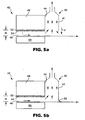
- FIG. 5a shows the chamber 40 positioned at the trailing edge 44 of the gap drying system 42.
- gas phase components are transported by drag from a moving web.
- the gas phase components in the gap between the web and the top plate can be a concern because it may be nominally saturated with the evaporative component.
- This component solvent or other component
- a gap drying system 42 includes a web 46 positioned between a condensing plate 48 and a hot plate 50.
- a gap, of distance H, is formed between the upper surface of the web 46 and the condensing plate 48.
- the condensing plate 48 includes a capillary surface 52 to convey condensed material away from the condensing surface 54.
- a chamber 40 is provided at the point where the web 46 exits the gap to collect the gas phase components exiting the gap drying system 42.
- the mass flow through the chamber may be assisted by applying a seal to a trailing edge of the chamber.
- the seal functions as a sweep to prevent gas from exiting the trailing edge of the chamber, thus forcing it into the chamber.
- the seal could include either a forced gas or mechanical seal.
- FIG. 5a depicts an optional forced gas air flow F in the direction of the downward arrow on the outer portion 41 of the chamber.
- the forced gas blocks any gas phase components carried by the moving web 46.
- the gas could be clean air, nitrogen, carbon dioxide or other inert gas systems.
- FIG. 5b illustrates the utilization of a flexible seal element 56 at the outer portion 41 of the chamber 40 to reduce the amount of dilution transported through the chamber 40.
- the flexible seal 56 could drag on the web 46 or be spaced at a small gap to the web 46. In this case, the gap is non-uniform, with H at the exit near the seal approaching zero.
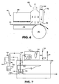
- the mechanical seal may also comprise a retractable sealing mechanism as depicted in FIG. 6 .
- the retractable sealing mechanism 76 is shown in an engaged position for normal continuous operation with a chamber 60 and a gap drying system 62, including condensing plate 68 and hot plate 70.
- the retractable sealing mechanism 76 may be set at a smaller gap to the surface of the web 66 than with other forms of mechanical seals.
- the smaller gap is more effective in removing the boundary layer of gas phase components from the moving web 66 for capture without possible scratching or damaging the coating or web surface.
- This gap to the surface of the web 66 could be 0.00508 cm to 0508 cm or more.
- the smaller gap is more effective in removing the boundary layer of gas phase components.
- the effectiveness of the retractable sealing mechanism 76 is improved by increasing the thickness of the seal while maintaining a sealing face 78 that corresponds to the web at the sealing point.
- the retractable sealing mechanism 76 With an idler roll 80 as shown in the FIG. 6 , the retractable sealing mechanism 76 has a radiused shape corresponding to the radius of the idler roll 80.
- the thickness of the retractable sealing mechanism could be 1.5 cm to more than 3 cm.
- the thicker plate increases the sealing area and thus making it more effective. The practical thickness will depend on factors such as idler radius and idler wrap angle.
- the seal may be moved to a retracted position through use of an actuator 82 or other mechanical means.
- the raised arrangement prevents contamination to the sealing mechanism 76, damage to the web 66, allows passage of overthick coatings, or allows passage of a splice or other upset condition.
- Those skilled in the art recognize that the retraction of the retractable sealing mechanism 76 could be automated and controlled for known upsets such as splices or coating overthicknesses, or even connected to a sensor (not shown) for upsets (such as a tip bar, laser inspection device etc.) to allow retraction for unanticipated events.
- the apparatus of the present invention utilizes a material supporting mechanism for securing the material in close proximity to the chamber to ensure an appropriate gap.
- Conventional material handling systems and devices are suitable for use with the present invention.
- the apparatus includes a chamber, as described above, which is then placed over the material to define a gap between a surface of the material and the lower periphery of the chamber.
- the chamber is constructed of conventional materials and may be designed to meet specific application standards.
- the chamber may exist as a stand-alone device or it may be placed in an enclosed environment, such as, for example, an oven enclosure. Additionally, the flame arresting devices and heating coils optionally placed in the chamber may include conventional recognized equipment and materials.
- An energy source as described above, is used to provide sufficient energy to the material in order to vaporize the at least one evaporative component in the material. Heating methods and heat transfer equipment generally recognized in the art are suitable for use with the present invention.
- the concentrated vapor stream collected in the chamber may be further separated utilizing conventional separation equipment and processes generally described as absorption, adsorption, membrane separation or condensation. Those skilled in the art are capable of selecting specific separation practices and equipment based on the vapor composition and desired separation efficiency.
- the present invention captures at least a portion of the vapor component without substantial dilution and without condensation of the vapor component in the drying system.
- the collection of the vapor component at high concentrations permits efficient recovery of the material.
- the absence of condensation in the drying system reduces product quality issues due to condensate falling onto the product.
- the present invention also utilizes relatively low air flow which significantly reduces the introduction of extraneous material into the drying system and thus prevents product quality problems with the finished product.
- an oven 100 with a direct fired heater box 102 was utilized in the present Example.
- the oven 100 had a supply air plenum 104 with multiple high velocity nozzles 106. These high velocity convection nozzles 106 were placed within 2.5 cm from the substrate material 108.
- the material 108 was a web of plastic film having a semi-rigid vinyl dispersion coated on the surface.
- the high velocity nozzles 106 provided high heat transfer to the material 108.
- the discharge air velocity at the nozzle exit was 20-30 meters per second at the oven temperature.
- the heater box had a recirculation fan 110 and a modulating direct fired burner 112. The heater box mixed the recirculation air 114 with fresh make up air 116 and passed this through the heater box 102.
- the direct fired burner 112 was modulated to control discharge air temperature at 150° to 200° C.
- the desired operating pressure of the oven is maintained by controlling oven exhaust 118 and the make up air 116.
- Chamber 120 is a 10 cm by 10 cm by 200 cm long structure made out of stainless steel. Multiple chambers (not shown) were mounted within 1.5 cm from the material 108 throughout the oven 100. Each chamber 120 had three 1.2 cm outlets at the top. The three outlets are joined in a 2 cm in diameter manifold 122.
- the manifold 122 was 2 cm in diameter and penetrated through the oven casing to outside the oven 100.
- the manifold 122 outside the oven body was connected to a condenser 124.
- the condenser 124 was a tube within a tube design and was made out of stainless steel.
- the inner tube was 2 cm in diameter and the outer tube was 3.5 cm in diameter.
- the condenser 124 had 2 cm in diameter plant chilled water inlet 126 and a 2 cm in diameter chilled water outlet 128. The plant chilled water was at 5°-10° C at the chilled water inlet 126.
- a vapor component from the material 108 was collected within chamber 120, subsequently condensed in condenser 124, and then collected in a separator 130. Clean gaseous flow from the separator 130 was routed to a vacuum pump 132 through a 2 cm in diameter PVC pipe.
- the vacuum pump 132 was controlled to maintain chamber 120 at a pressure gradient with respect to the oven operating pressure. The discharge of the vacuum pump 132 was routed back to the oven body.
- This method collects a substantial amount of vaporized components from the material 108 without substantial dilution. Condensed material build up was observed in the internal area of the oven 100 after 4000 hours of operation. This corresponds to an approximate 100% improvement from the conventional system. Condensate had been observed after 2000 hours of operation prior to installation of the devices.
- M5 represents the time-average mass flow per unit width of any additional dilution stream provided to the chamber (for example the makeup air stream in convection ovens) in kg/second/meter.
- the width (“w") of the material, in centimeters, is the measurement (of the gap) in the direction perpendicular to the motion of the material.
- the time-average gas phase velocity (“ ⁇ v>”) was defined above and has units of meters per second.
- the pressure difference (“ ⁇ P") is the pressure gradient between the lower periphery of the chamber and outside the chamber in Pascals.
- the material velocity (“V”) is measured in meters per second.
- a typical air convection drying system consisted of a large enclosure containing high velocity convection nozzles.
- the material in web form, entered through an entrance gap having a width of 76.2 cm and a height of 10.2 cm.
- the material exited through an exit slot having the same dimensions as the entrance gap.
- the material was transported through the center of the gap at a velocity of about 1 meter/second.
- the material consisted of a polyester web with an organic solvent based coating and was dried as it passed through the enclosure.
- the dryer system operating conditions were as follows.
- the overall recirculation flow within the chamber of 18.6 kg/second/meter and with the enclosure (chamber) pressure set to -5 Pa.
- the exhaust flow through the chamber M4 was 7.43 kg/second/meter.
- M1 was calculated using Equation 4.
- the M2 value was calculated assuming the flow stream, M4, was maintained at 20% Lower Flammability Limit (LFL) for a solvent with LFL of 1.5 % by volume solvent concentration.
- LFL Lower Flammability Limit
- the flow of make up air M5 into the chamber was 6.7 kg/second/meter.
- a typical inert convection drying system consisted of a large enclosure containing high velocity convection nozzles. The material entered through an entrance gap having a width of 76.2 cm and a height of 2.54 cm. The material exited through an exit gap having the same dimensions as the entrance gap. The material was transported through the center of the gaps at a velocity of 1 meter/second. The material consisted of a polyester web with an organic solvent based coating and was dried as it passed through the enclosure.
- the dryer system operating conditions were as follows: The overall recirculation flow within the chamber of 5.66 kg/second/meter and with the enclosure pressure set to 2.5 Pa. The exhaust flow through the chamber M4 was 1.48 kg/second/meter.
- the flow through the entrance and exit gaps out of the chamber, M1, resulting from the positive 2.5 Pa pressure gradient was 0.12 kg/second/meter.
- M1 was calculated using Equation 4.
- the flow resulting from the evaporation of the coating solution solvents, M2, (i.e., drying) was 0.03 kg/second/meter. This was determined from the 2% by volume of solvent recovered (at the separation device) out of M4 prior to being returned to the dryer as part of dilution stream M5.
- the net flow into the gap resulting from the motion of the material through the chamber, M3, was 0.
- the additional dilution stream M5 was 1.57 kg/second/meter. This was made up of return flow from the separation device and the inert gas makeup stream.
- the vapor collection apparatus was integrated with a conventional gap drying system to capture and collect the gas phase components exiting the gap dryer.
- the web was conveyed by a conveying system through the apparatus of the present invention.
- the web was comprised of polyester film coated with inorganic material dispersed in ethanol and water.
- the web entered through an entrance gap having a width, w, of 30.5 cm and a height, H, of 0.32 cm.
- the material exited through an exit gap having the same dimensions as the entrance gap.
- the web was transported through the gap and underneath the chamber at a velocity of 0.015 meter/second.
- the exhaust flow M4 was measured to be 0.0066 kg/second/meter.
- a web was conveyed by a conveying system through an apparatus substantially similar to that disclosed in FIGS. 2-4 .
- the web was comprised of polyester film coated with a material consisting of a 10% styrene butadiene copolymer solution in toluene.
- the web passed under a chamber thereby forming a gap between the lower periphery of the chamber and the exposed surface of the material.
- the gap had a width, w, of 15 cm and a height, H, of 0.32 cm.
- the material exited from underneath the chamber at a gap having the same dimensions as the entrance gap.
- the web was transported through the gap and underneath the chamber at a velocity of 0.0254 meter/second.
- the dryer system operating conditions were as follows.
- the heating element was maintained at 87° C and the chamber was maintained at 50° C.
- the exhaust flow (M4) was measured to be 0.00155 kg/second/meter.
- the flow through the entrance and exit gaps out of the chamber, M1, resulting from the induced pressure gradient was 0.00094 kg/second/meter.
- M1 was calculated using Equation 1.
- the flow resulting from the evaporation of the toluene, M2, was 0.00061 kg/second/meter.
- the net flow into the gap resulting from the motion of the material through the chamber, M3, was 0. There was no additional dilution streams M5.
Landscapes
- Engineering & Computer Science (AREA)
- Mechanical Engineering (AREA)
- General Engineering & Computer Science (AREA)
- Textile Engineering (AREA)
- Drying Of Solid Materials (AREA)
- Exposure Of Semiconductors, Excluding Electron Or Ion Beam Exposure (AREA)
- Physical Vapour Deposition (AREA)
- Drying Of Semiconductors (AREA)
Claims (26)
- Appareil (10a) qui traite un substrat mobile (12) d'une longueur indéfinie, comprenant :(a) une surface de contrôle (15) située à proximité étroite d'une surface (14) du substrat (12) et qui définit un écart de contrôle (G) entre le substrat (12) et la surface de contrôle (15),(b) une première chambre (17) proche de la surface de contrôle (15), la première chambre (17) présentant un dispositif (21) d'introduction de gaz,(c) une deuxième chambre (16a) proche de la surface de contrôle (15), la deuxième chambre (16a) présentant un dispositif (18a) d'évacuation de gaz et la surface de contrôle (15) et les chambres (17, 16a) définissant ensemble une zone dans laquelle la phase gazeuse adjacente présente une masse donnée,
où lors de l'induction du transport d'au moins une partie de ladite masse dans ladite zone :M1 représente l'écoulement massique net total moyen dans le temps par unité de largeur vers ou hors de la zone, résultant de gradients de pression,M1' représente l'écoulement massique net total moyen dans le temps de gaz par unité de largeur vers la zone à travers la première chambre (17) depuis le dispositif (21) d'introduction de gaz,M2 représente l'écoulement massique moyen dans le temps par unité de largeur depuis ou vers au moins une surface principale du substrat (12) dans la zone,M3 représente l'écoulement massique net total moyen dans le temps par unité de largeur vers la zone, résultant du déplacement du substrat (12) etM4 représente le débit moyen dans le temps du transport de masse par unité de largeur à travers le dispositif (18a) d'évacuation de gaz, de telle sorte que M1 + M1' + M2 + M3 = M4,les composants souhaités de la phase gazeuse sont transportés à travers ou collectés à partir de la zone essentiellement sans dilution, et :(d) M1 est positif et il existe une petite quantité d'écoulement d'entrée de gaz dans la zone, ou(e) la première chambre (17) définit un premier écart (G1) entre la première chambre (17) et le substrat (12), la deuxième chambre (16a) définit un deuxième écart (G2) entre la deuxième chambre (16a) et le substrat (12) et le premier écart (G1), le deuxième écart (G2) et l'écart de contrôle (G) sont tous égaux ou inférieurs à 3 cm ou(f) la surface de contrôle (15) est une surface de condensation. - Appareil selon la revendication 1, dans lequel M1 présente une valeur supérieure à zéro mais inférieure ou égale à 0,25 kg/seconde/mètre.
- Appareil selon la revendication 2, dans lequel M1' présente une valeur supérieure à zéro mais inférieure ou égale à 0,25 kg/seconde/mètre.
- Appareil selon la revendication 1, dans lequel la première chambre et la deuxième chambre sont situées à des extrémités opposées de la surface de contrôle.
- Appareil selon la revendication 1, dans lequel la surface de contrôle est une surface de condensation.
- Appareil selon la revendication 1, dans lequel la distance entre le dispositif d'introduction de gaz et la surface du substrat est approximativement égale à l'écart de contrôle.
- Appareil selon la revendication 1, dans lequel le gaz est un gaz inerte.
- Appareil selon la revendication 1, dans lequel le gaz induit un gradient thermique dans l'écart de contrôle.
- Appareil selon la revendication 1, dans lequel le dispositif d'introduction de gaz est une lame de gaz, un rideau de gaz ou un collecteur de gaz.
- Appareil selon la revendication 1, dans lequel la première chambre définit un premier écart situé entre la première chambre et le substrat, la deuxième chambre définit un deuxième écart entre la deuxième chambre et le substrat et le premier écart, le deuxième écart et l'écart de contrôle sont tous égaux ou inférieurs à 3 cm.
- Appareil selon la revendication 10, dans lequel le premier écart, le deuxième écart et l'écart de contrôle présentent tous une hauteur égale.
- Appareil selon la revendication 10, dans lequel le premier écart et/ou le deuxième écart présentent une hauteur différente de celle de l'écart de contrôle.
- Appareil selon la revendication 10, dans lequel le premier écart, le deuxième écart et l'écart de contrôle sont tous égaux ou inférieurs à 0,75 cm.
- Procédé de traitement d'un substrat mobile (12) d'une longueur indéfinie, le procédé comprenant les étapes qui consistent à :(a) placer une surface de contrôle (15) à proximité étroite d'une surface (14) du substrat (12) pour définir un écart de contrôle (G) entre le substrat (12) et la surface de contrôle (15),(b) placer une première chambre (17) à proximité de la surface de contrôle (15), la première chambre (17) présentant un dispositif (21) d'introduction de gaz,(c) placer une deuxième chambre (16a) à proximité de la surface de contrôle (15), la deuxième chambre (16a) présentant un dispositif (18a) d'évacuation de gaz et la surface de contrôle (15) et les chambres (17, 16a) définissant ensemble une zone dans laquelle la phase gazeuse adjacente présente une masse donnée et(d) induire le transport d'au moins une partie de la masse dans la zone, de manière à ce que si :M1 représente l'écoulement massique net total moyen dans le temps par unité de largeur vers ou hors de la zone, résultant des gradients de pression,M1' représente l'écoulement massique net total moyen dans le temps de gaz par unité de largeur vers la zone, à travers la première chambre (17) depuis le dispositif (21) d'introduction de gaz,M2 représente l'écoulement massique moyen dans le temps par unité de largeur depuis ou vers au moins une surface principale du substrat (12) dans la zone,M3 représente l'écoulement massique net total moyen dans le temps par unité de largeur vers la zone, résultant du déplacement du substrat (12) etM4 représente le débit moyen dans le temps de transport de masse par unité de largeur à travers le dispositif (18a) d'évacuation de gaz, de telle sorte que M1 + M1' + M2 + M3 = M4,les composants souhaités de la phase gazeuse sont transportés à travers ou collectés à partir de la zone essentiellement sans dilution et :(d) M1 est positif et il existe une petite quantité d'écoulement d'entrée de gaz dans la zone, ou(e) la première chambre (17) définit un premier écart (G1) entre la première chambre (17) et le substrat (12), la deuxième chambre (16a) définit un deuxième écart (G2) entre la deuxième chambre (16a) et le substrat (12) et le premier écart (G1), le deuxième écart (G2) et l'écart de contrôle (G) sont tous égaux ou inférieurs à 3 cm ou(f) la surface de contrôle est une surface de condensation.
- Procédé selon la revendication 14, dans lequel M1 présente une valeur supérieure à zéro mais inférieure ou égale à 0,25 kg/seconde/mètre.
- Procédé selon la revendication 15, dans lequel M1' présente une valeur supérieure à zéro mais inférieure ou égale à 0,25 kg/seconde/mètre.
- Procédé selon la revendication 14, dans lequel la première chambre et la deuxième chambre sont situées à des extrémités opposées de la surface de contrôle.
- Procédé selon la revendication 14, dans lequel la surface de contrôle est une surface de condensation.
- Procédé selon la revendication 14, dans lequel la distance entre le dispositif d'introduction de gaz et la surface du substrat est approximativement égale à l'écart de contrôle.
- Procédé selon la revendication 14, dans lequel le gaz est un gaz inerte.
- Procédé selon la revendication 14, dans lequel le gaz induit un gradient thermique dans l'écart de contrôle.
- Procédé selon la revendication 14, dans lequel le dispositif d'introduction de gaz est une lame de gaz, un rideau de gaz ou un collecteur de gaz.
- Procédé selon la revendication 14, dans lequel la première chambre définit un premier écart entre la première chambre et le substrat, la deuxième chambre définit un deuxième écart entre la deuxième chambre et le substrat et le premier écart, le deuxième écart et l'écart de contrôle sont tous égaux ou inférieurs à 3 cm.
- Procédé selon la revendication 23, dans lequel le premier écart, le deuxième écart et l'écart de contrôle présentent tous une hauteur égale.
- Procédé selon la revendication 23, dans lequel le premier écart et/ou le deuxième écart présentent une hauteur différente de celle de l'écart de contrôle.
- Procédé selon la revendication 23, dans lequel le premier écart, le deuxième écart et l'écart de contrôle sont tous égaux ou inférieurs à 0,75 cm.
Applications Claiming Priority (2)
| Application Number | Priority Date | Filing Date | Title |
|---|---|---|---|
| US10/421,195 US20030230003A1 (en) | 2000-09-24 | 2003-04-23 | Vapor collection method and apparatus |
| PCT/US2004/007193 WO2004094930A1 (fr) | 2003-04-23 | 2004-03-08 | Procede et appareil de collecte de vapeur |
Publications (2)
| Publication Number | Publication Date |
|---|---|
| EP1620688A1 EP1620688A1 (fr) | 2006-02-01 |
| EP1620688B1 true EP1620688B1 (fr) | 2011-07-27 |
Family
ID=33309574
Family Applications (1)
| Application Number | Title | Priority Date | Filing Date |
|---|---|---|---|
| EP04718575A Expired - Lifetime EP1620688B1 (fr) | 2003-04-23 | 2004-03-08 | Procede et appareil de collecte de vapeur |
Country Status (9)
| Country | Link |
|---|---|
| US (3) | US20030230003A1 (fr) |
| EP (1) | EP1620688B1 (fr) |
| JP (2) | JP2006524309A (fr) |
| KR (1) | KR101100461B1 (fr) |
| CN (1) | CN100422678C (fr) |
| AT (1) | ATE518105T1 (fr) |
| BR (1) | BRPI0409605A (fr) |
| MX (1) | MXPA05011288A (fr) |
| WO (1) | WO2004094930A1 (fr) |
Families Citing this family (14)
| Publication number | Priority date | Publication date | Assignee | Title |
|---|---|---|---|---|
| JP4118194B2 (ja) * | 2003-06-02 | 2008-07-16 | 横河電機株式会社 | 洗浄装置 |
| FR2867263B1 (fr) * | 2004-03-02 | 2006-05-26 | Solaronics Irt | Installation de sechage pour une bande defilante, notamment pour une bande de papier |
| US7926200B2 (en) | 2004-03-02 | 2011-04-19 | Nv Bekaert Sa | Infrared drier installation for passing web |
| US8046934B2 (en) * | 2006-01-25 | 2011-11-01 | Nv Bekaert Sa | Convective system for a dryer installation |
| JP4527670B2 (ja) * | 2006-01-25 | 2010-08-18 | 東京エレクトロン株式会社 | 加熱処理装置、加熱処理方法、制御プログラムおよびコンピュータ読取可能な記憶媒体 |
| US7877895B2 (en) * | 2006-06-26 | 2011-02-01 | Tokyo Electron Limited | Substrate processing apparatus |
| JP4901395B2 (ja) * | 2006-09-26 | 2012-03-21 | 富士フイルム株式会社 | 塗布膜の乾燥方法 |
| CN101865852A (zh) * | 2010-03-16 | 2010-10-20 | 苏州市玮琪生物科技有限公司 | 一种总胆固醇比色卡 |
| ES2625072T3 (es) | 2011-08-11 | 2017-07-18 | Avery Dennison Corporation | Secador de placas y método de secado de revestimientos a base de disolvente |
| US20190283063A1 (en) * | 2018-03-14 | 2019-09-19 | Adam Zax | Method and apparatus for inline coating of substrates |
| DE102018124521A1 (de) | 2018-10-04 | 2020-04-09 | Brückner Maschinenbau GmbH & Co. KG | Behandlungsanlage für eine durch einen Behandlungsofen hindurchführbare flexible Materialbahn, insbesondere Kunststofffolie |
| MX2023010513A (es) * | 2021-03-08 | 2023-09-20 | Monsanto Technology Llc | Sistemas y metodos para el almacenamiento de polen a largo plazo. |
| KR102472215B1 (ko) * | 2022-01-11 | 2022-11-30 | 주식회사 강원이솔루션 | 전기히터를 구비한, 이차전지 제조용 분말원료 건조장치 |
| CN116288940B (zh) * | 2023-03-17 | 2023-10-10 | 浙江中超新材料股份有限公司 | 一种三层式喷胶干燥箱及其控制方法 |
Family Cites Families (63)
| Publication number | Priority date | Publication date | Assignee | Title |
|---|---|---|---|---|
| US1494830A (en) * | 1923-08-20 | 1924-05-20 | Robert W Cook | Process of manufacturing cellulose acetate |
| DE499308C (de) | 1927-06-29 | 1930-06-05 | Hermann Und Alfred Escher Akt | Einrichtung zur Rueckgewinnung von fluechtigen Loesungsmitteln bei mit Bandbahn arbeitenden Maschinen und Trockenapparaten |
| US2157388A (en) * | 1937-01-22 | 1939-05-09 | Interchem Corp | Method of printing and setting a printing ink |
| GB713612A (en) | 1951-10-29 | 1954-08-11 | Petrus Vial | Process and apparatus for the recovery of solvents on long webs |
| BE530378A (fr) * | 1953-08-20 | 1900-01-01 | ||
| US3071869A (en) * | 1958-10-16 | 1963-01-08 | Time Inc | Web drying apparatus |
| US3408748A (en) * | 1966-08-17 | 1968-11-05 | Dow Chemical Co | Drying and recovery process |
| US3542640A (en) * | 1967-03-23 | 1970-11-24 | Procter & Gamble | Method for drying a wet foam containing cellulosic fibers |
| US3452447A (en) * | 1967-05-25 | 1969-07-01 | Thomas A Gardner | Web positioning means and method |
| AT321257B (de) | 1971-05-26 | 1975-03-25 | Koreska Gmbh W | Anlage zur Rückgewinnung flüchtiger Lösungsmittel |
| US3931684A (en) * | 1973-10-15 | 1976-01-13 | J. J. Baker Company Limited | Vapor chamber for drying |
| US4051278A (en) * | 1975-06-06 | 1977-09-27 | Eastman Kodak Company | Method for reducing mottle in coating a support with a liquid coating composition |
| US4012847A (en) * | 1975-11-24 | 1977-03-22 | Autosonics Inc. | Solvent recovery system |
| US4053990A (en) * | 1976-03-03 | 1977-10-18 | Sav-Sol Drying Systems, Inc. | Differential pressure drying and solvent recovery unit |
| US4263724A (en) * | 1979-06-14 | 1981-04-28 | Vits-Maschinenbau Gmbh | Traveling web drying apparatus |
| US4223450A (en) * | 1979-07-05 | 1980-09-23 | Airco, Inc. | Methods and apparatus for controlling gas flows |
| US4268977A (en) * | 1979-12-03 | 1981-05-26 | Exxon Research & Engineering Company | Sealing apparatus for ovens |
| US4287240A (en) | 1980-04-11 | 1981-09-01 | Eastman Kodak Company | Coating apparatus provided with a protective shield |
| GB2079913A (en) | 1980-05-09 | 1982-01-27 | Crosfield Electronics Ltd | Web drying apparatus |
| US4365423A (en) * | 1981-03-27 | 1982-12-28 | Eastman Kodak Company | Method and apparatus for drying coated sheet material |
| US4369584A (en) * | 1981-04-16 | 1983-01-25 | W. R. Grace & Co. | Preventing air film between web and roller |
| US4462169A (en) * | 1982-02-19 | 1984-07-31 | W. R. Grace & Company | Web dryer solvent vapor control means |
| US4926567A (en) * | 1985-07-04 | 1990-05-22 | Fuji Photo Film Co., Ltd. | Process and apparatus for drying coated web |
| SE458065B (sv) | 1986-10-16 | 1989-02-20 | Tore Eklund | Parabolantennfaeste som aer roerligt foer instaellning saavael foer utstraeckning i lodplanet som foer vinkel instaellning i lodplanet |
| JPS63158166A (ja) * | 1986-12-23 | 1988-07-01 | Fuji Photo Film Co Ltd | 帯状物の乾燥方法 |
| US4752217A (en) * | 1987-08-28 | 1988-06-21 | Essex Group, Inc. | Wire coating oven including wire cooling apparatus |
| FI78756C (fi) | 1988-04-25 | 1989-09-11 | Valmet Paper Machinery Inc | Foerfarande och anordning vid torkning av en roerlig bana. |
| JPH0248132Y2 (fr) * | 1988-09-16 | 1990-12-18 | ||
| DE4009797A1 (de) * | 1990-03-27 | 1991-10-02 | Pagendarm Gmbh | Verfahren und anordnung zum kondensieren von dampffoermigen substanzen |
| US5248349A (en) * | 1992-05-12 | 1993-09-28 | Solar Cells, Inc. | Process for making photovoltaic devices and resultant product |
| DE4226107A1 (de) * | 1992-08-07 | 1994-02-10 | Vits Maschinenbau Gmbh | Trocknungsanlage |
| DE4243515A1 (de) | 1992-12-22 | 1994-06-23 | Basf Magnetics Gmbh | Abdichtvorrichtung am Einlauf und Auslauf einer Behandlungsstrecke für Warenbahnen |
| GB9323954D0 (en) * | 1993-11-19 | 1994-01-05 | Spooner Ind Ltd | Improvements relating to web drying |
| CN2187497Y (zh) | 1993-11-20 | 1995-01-18 | 熊已焯 | 光敏漆滚涂机 |
| US6117237A (en) * | 1994-01-04 | 2000-09-12 | 3M Innovative Properties Company | Coater die enclosure system |
| US5524363A (en) * | 1995-01-04 | 1996-06-11 | W. R. Grace & Co.-Conn. | In-line processing of a heated and reacting continuous sheet of material |
| US5555635A (en) * | 1995-01-18 | 1996-09-17 | W. R. Grace & Co.-Conn. | Control and arrangement of a continuous process for an industrial dryer |
| US5853801A (en) * | 1995-09-04 | 1998-12-29 | Fuji Photo Film Co., Ltd. | Process for the preparation of continuous optical compensatory sheet |
| US5694701A (en) | 1996-09-04 | 1997-12-09 | Minnesota Mining And Manufacturing Company | Coated substrate drying system |
| US5581905A (en) | 1995-09-18 | 1996-12-10 | Minnesota Mining And Manufacturing Company | Coated substrate drying system |
| KR100456683B1 (ko) * | 1995-09-18 | 2005-01-15 | 미네소타 마이닝 앤드 매뉴팩춰링 캄파니 | 응축 기구를 포함하는 성분 분리 시스템 |
| US6015593A (en) | 1996-03-29 | 2000-01-18 | 3M Innovative Properties Company | Method for drying a coating on a substrate and reducing mottle |
| US5813133A (en) | 1996-09-04 | 1998-09-29 | Minnesota Mining And Manufacturing Company | Coated substrate drying system with magnetic particle orientation |
| US6007318A (en) * | 1996-12-20 | 1999-12-28 | Z Corporation | Method and apparatus for prototyping a three-dimensional object |
| JPH10202175A (ja) * | 1997-01-28 | 1998-08-04 | Valmet Oy | 紙ウエブ等のコーティングの乾燥方法および装置 |
| US5906862A (en) * | 1997-04-02 | 1999-05-25 | Minnesota Mining And Manufacturing Company | Apparatus and method for drying a coating on a substrate |
| US6047151A (en) * | 1998-05-06 | 2000-04-04 | Imation Corp. | Drying system and method for an electrophotographic imaging system |
| US6256904B1 (en) * | 1998-05-06 | 2001-07-10 | Imation Corp. | Controlling float height of moving substrate over curved plate |
| US6207020B1 (en) * | 1998-05-12 | 2001-03-27 | International Paper Company | Method for conditioning paper and paperboard webs |
| US6134808A (en) | 1998-05-18 | 2000-10-24 | Minnesota Mining And Manufacturing Company | Gap drying with insulation layer between substrate and heated platen |
| US6308436B1 (en) * | 1998-07-01 | 2001-10-30 | The Procter & Gamble Company | Process for removing water from fibrous web using oscillatory flow-reversing air or gas |
| US6280573B1 (en) * | 1998-08-12 | 2001-08-28 | Kimberly-Clark Worldwide, Inc. | Leakage control system for treatment of moving webs |
| DE19919234A1 (de) * | 1999-04-28 | 2000-11-16 | Fontaine Eng & Maschinen Gmbh | Beschichtungsanlage |
| JP4147370B2 (ja) | 1999-12-17 | 2008-09-10 | 富士フイルム株式会社 | 塗布膜の乾燥方法及び装置 |
| DE10007004B4 (de) * | 2000-02-16 | 2006-04-06 | Lindauer Dornier Gmbh | Verfahren zum Führen einer Warenbahn und Wärmebehandlungsvorrichtung |
| MXPA03002499A (es) * | 2000-09-21 | 2004-05-24 | 3M Innovative Properties Co | Metodo y aparato para coleccion de vapor. |
| US6553689B2 (en) * | 2000-09-24 | 2003-04-29 | 3M Innovative Properties Company | Vapor collection method and apparatus |
| CN1357485A (zh) * | 2000-12-06 | 2002-07-10 | 富士胶片株式会社 | 无接触基材输送装置 |
| US6656017B2 (en) * | 2001-04-24 | 2003-12-02 | David P. Jackson | Method and apparatus for creating an open cell micro-environment for treating a substrate with an impingement spray |
| JP4699660B2 (ja) | 2001-09-27 | 2011-06-15 | 富士フイルム株式会社 | 塗布膜の乾燥方法および装置 |
| JP4631242B2 (ja) | 2001-09-27 | 2011-02-16 | 富士フイルム株式会社 | 塗布膜の乾燥方法および装置 |
| JP2003112109A (ja) | 2001-10-01 | 2003-04-15 | Toray Ind Inc | フィルムの製造方法およびコーティング装置 |
| JP2003251251A (ja) | 2002-03-01 | 2003-09-09 | Konica Corp | 乾燥装置、乾燥方法及びこれらを用いた画像形成材料の製造方法 |
-
2003
- 2003-04-23 US US10/421,195 patent/US20030230003A1/en not_active Abandoned
-
2004
- 2004-03-08 CN CNB2004800108951A patent/CN100422678C/zh not_active Expired - Fee Related
- 2004-03-08 AT AT04718575T patent/ATE518105T1/de not_active IP Right Cessation
- 2004-03-08 WO PCT/US2004/007193 patent/WO2004094930A1/fr active Search and Examination
- 2004-03-08 KR KR1020057020012A patent/KR101100461B1/ko active IP Right Grant
- 2004-03-08 EP EP04718575A patent/EP1620688B1/fr not_active Expired - Lifetime
- 2004-03-08 JP JP2006507005A patent/JP2006524309A/ja active Pending
- 2004-03-08 BR BRPI0409605-3A patent/BRPI0409605A/pt not_active Application Discontinuation
- 2004-03-08 MX MXPA05011288A patent/MXPA05011288A/es active IP Right Grant
-
2006
- 2006-03-02 US US11/366,291 patent/US7918038B2/en not_active Expired - Fee Related
- 2006-04-11 US US11/401,508 patent/US7971370B2/en not_active Expired - Fee Related
-
2010
- 2010-08-06 JP JP2010177803A patent/JP2010281563A/ja active Pending
Also Published As
| Publication number | Publication date |
|---|---|
| US20060191160A1 (en) | 2006-08-31 |
| ATE518105T1 (de) | 2011-08-15 |
| CN100422678C (zh) | 2008-10-01 |
| JP2010281563A (ja) | 2010-12-16 |
| CN1777784A (zh) | 2006-05-24 |
| KR101100461B1 (ko) | 2011-12-29 |
| WO2004094930A1 (fr) | 2004-11-04 |
| US20060179680A1 (en) | 2006-08-17 |
| MXPA05011288A (es) | 2006-01-24 |
| KR20050114726A (ko) | 2005-12-06 |
| EP1620688A1 (fr) | 2006-02-01 |
| US7971370B2 (en) | 2011-07-05 |
| US7918038B2 (en) | 2011-04-05 |
| US20030230003A1 (en) | 2003-12-18 |
| JP2006524309A (ja) | 2006-10-26 |
| BRPI0409605A (pt) | 2006-04-18 |
Similar Documents
| Publication | Publication Date | Title |
|---|---|---|
| US7971370B2 (en) | Vapor collection method and apparatus | |
| US6553689B2 (en) | Vapor collection method and apparatus | |
| EP1732704B1 (fr) | Procede d'enrobage et dispositif correspondant | |
| US7918039B2 (en) | Coating process and apparatus | |
| US6682598B1 (en) | Apparatus for casting and drying ceramic tape | |
| US20180195796A1 (en) | Inerted plate dryer and method of drying solvent based coating | |
| NL8104466A (nl) | Werkwijze en inrichting voor het drogen van oplosmiddelhoudend materiaal. | |
| EP1337799B1 (fr) | Procede et appareil de collecte de vapeur | |
| US4798007A (en) | Explosion-proof, pollution-free infrared dryer | |
| HU215776B (hu) | Eljárás és berendezés a szárító burkolatából kilépő folytonos szalaganyag hűtésére és az oldószer-kondenzáció csökkentésére | |
| CN103814266B (zh) | 干燥被施用于基底的流体膜的方法和装置 | |
| DE60126972T2 (de) | Verfahren und vorrichtung zum sammeln von dampf | |
| CN100404990C (zh) | 蒸气收集方法 | |
| MXPA06011036A (es) | Proceso y aparato de recubrimiento | |
| Kaper et al. | Oven Drying of Inkjet‐Printed Functional Fluids on Industrial Scale |
Legal Events
| Date | Code | Title | Description |
|---|---|---|---|
| PUAI | Public reference made under article 153(3) epc to a published international application that has entered the european phase |
Free format text: ORIGINAL CODE: 0009012 |
|
| 17P | Request for examination filed |
Effective date: 20051121 |
|
| AK | Designated contracting states |
Kind code of ref document: A1 Designated state(s): AT BE BG CH CY CZ DE DK EE ES FI FR GB GR HU IE IT LI LU MC NL PL PT RO SE SI SK TR |
|
| DAX | Request for extension of the european patent (deleted) | ||
| 17Q | First examination report despatched |
Effective date: 20100616 |
|
| GRAP | Despatch of communication of intention to grant a patent |
Free format text: ORIGINAL CODE: EPIDOSNIGR1 |
|
| GRAS | Grant fee paid |
Free format text: ORIGINAL CODE: EPIDOSNIGR3 |
|
| GRAA | (expected) grant |
Free format text: ORIGINAL CODE: 0009210 |
|
| AK | Designated contracting states |
Kind code of ref document: B1 Designated state(s): AT BE BG CH CY CZ DE DK EE ES FI FR GB GR HU IE IT LI LU MC NL PL PT RO SE SI SK TR |
|
| REG | Reference to a national code |
Ref country code: GB Ref legal event code: FG4D |
|
| REG | Reference to a national code |
Ref country code: CH Ref legal event code: EP |
|
| REG | Reference to a national code |
Ref country code: DE Ref legal event code: R096 Ref document number: 602004033634 Country of ref document: DE Effective date: 20110915 |
|
| REG | Reference to a national code |
Ref country code: NL Ref legal event code: VDEP Effective date: 20110727 |
|
| REG | Reference to a national code |
Ref country code: AT Ref legal event code: MK05 Ref document number: 518105 Country of ref document: AT Kind code of ref document: T Effective date: 20110727 |
|
| PG25 | Lapsed in a contracting state [announced via postgrant information from national office to epo] |
Ref country code: PT Free format text: LAPSE BECAUSE OF FAILURE TO SUBMIT A TRANSLATION OF THE DESCRIPTION OR TO PAY THE FEE WITHIN THE PRESCRIBED TIME-LIMIT Effective date: 20111128 Ref country code: SE Free format text: LAPSE BECAUSE OF FAILURE TO SUBMIT A TRANSLATION OF THE DESCRIPTION OR TO PAY THE FEE WITHIN THE PRESCRIBED TIME-LIMIT Effective date: 20110727 Ref country code: FI Free format text: LAPSE BECAUSE OF FAILURE TO SUBMIT A TRANSLATION OF THE DESCRIPTION OR TO PAY THE FEE WITHIN THE PRESCRIBED TIME-LIMIT Effective date: 20110727 Ref country code: BE Free format text: LAPSE BECAUSE OF FAILURE TO SUBMIT A TRANSLATION OF THE DESCRIPTION OR TO PAY THE FEE WITHIN THE PRESCRIBED TIME-LIMIT Effective date: 20110727 Ref country code: NL Free format text: LAPSE BECAUSE OF FAILURE TO SUBMIT A TRANSLATION OF THE DESCRIPTION OR TO PAY THE FEE WITHIN THE PRESCRIBED TIME-LIMIT Effective date: 20110727 |
|
| PG25 | Lapsed in a contracting state [announced via postgrant information from national office to epo] |
Ref country code: CY Free format text: LAPSE BECAUSE OF FAILURE TO SUBMIT A TRANSLATION OF THE DESCRIPTION OR TO PAY THE FEE WITHIN THE PRESCRIBED TIME-LIMIT Effective date: 20110727 Ref country code: AT Free format text: LAPSE BECAUSE OF FAILURE TO SUBMIT A TRANSLATION OF THE DESCRIPTION OR TO PAY THE FEE WITHIN THE PRESCRIBED TIME-LIMIT Effective date: 20110727 Ref country code: PL Free format text: LAPSE BECAUSE OF FAILURE TO SUBMIT A TRANSLATION OF THE DESCRIPTION OR TO PAY THE FEE WITHIN THE PRESCRIBED TIME-LIMIT Effective date: 20110727 Ref country code: SI Free format text: LAPSE BECAUSE OF FAILURE TO SUBMIT A TRANSLATION OF THE DESCRIPTION OR TO PAY THE FEE WITHIN THE PRESCRIBED TIME-LIMIT Effective date: 20110727 Ref country code: GR Free format text: LAPSE BECAUSE OF FAILURE TO SUBMIT A TRANSLATION OF THE DESCRIPTION OR TO PAY THE FEE WITHIN THE PRESCRIBED TIME-LIMIT Effective date: 20111028 |
|
| PG25 | Lapsed in a contracting state [announced via postgrant information from national office to epo] |
Ref country code: SK Free format text: LAPSE BECAUSE OF FAILURE TO SUBMIT A TRANSLATION OF THE DESCRIPTION OR TO PAY THE FEE WITHIN THE PRESCRIBED TIME-LIMIT Effective date: 20110727 Ref country code: CZ Free format text: LAPSE BECAUSE OF FAILURE TO SUBMIT A TRANSLATION OF THE DESCRIPTION OR TO PAY THE FEE WITHIN THE PRESCRIBED TIME-LIMIT Effective date: 20110727 |
|
| PG25 | Lapsed in a contracting state [announced via postgrant information from national office to epo] |
Ref country code: RO Free format text: LAPSE BECAUSE OF FAILURE TO SUBMIT A TRANSLATION OF THE DESCRIPTION OR TO PAY THE FEE WITHIN THE PRESCRIBED TIME-LIMIT Effective date: 20110727 Ref country code: IT Free format text: LAPSE BECAUSE OF FAILURE TO SUBMIT A TRANSLATION OF THE DESCRIPTION OR TO PAY THE FEE WITHIN THE PRESCRIBED TIME-LIMIT Effective date: 20110727 Ref country code: EE Free format text: LAPSE BECAUSE OF FAILURE TO SUBMIT A TRANSLATION OF THE DESCRIPTION OR TO PAY THE FEE WITHIN THE PRESCRIBED TIME-LIMIT Effective date: 20110727 |
|
| PLBE | No opposition filed within time limit |
Free format text: ORIGINAL CODE: 0009261 |
|
| STAA | Information on the status of an ep patent application or granted ep patent |
Free format text: STATUS: NO OPPOSITION FILED WITHIN TIME LIMIT |
|
| PG25 | Lapsed in a contracting state [announced via postgrant information from national office to epo] |
Ref country code: DK Free format text: LAPSE BECAUSE OF FAILURE TO SUBMIT A TRANSLATION OF THE DESCRIPTION OR TO PAY THE FEE WITHIN THE PRESCRIBED TIME-LIMIT Effective date: 20110727 |
|
| 26N | No opposition filed |
Effective date: 20120502 |
|
| REG | Reference to a national code |
Ref country code: DE Ref legal event code: R097 Ref document number: 602004033634 Country of ref document: DE Effective date: 20120502 |
|
| PG25 | Lapsed in a contracting state [announced via postgrant information from national office to epo] |
Ref country code: MC Free format text: LAPSE BECAUSE OF NON-PAYMENT OF DUE FEES Effective date: 20120331 |
|
| REG | Reference to a national code |
Ref country code: CH Ref legal event code: PL |
|
| GBPC | Gb: european patent ceased through non-payment of renewal fee |
Effective date: 20120308 |
|
| REG | Reference to a national code |
Ref country code: FR Ref legal event code: ST Effective date: 20121130 |
|
| REG | Reference to a national code |
Ref country code: IE Ref legal event code: MM4A |
|
| PG25 | Lapsed in a contracting state [announced via postgrant information from national office to epo] |
Ref country code: FR Free format text: LAPSE BECAUSE OF NON-PAYMENT OF DUE FEES Effective date: 20120402 Ref country code: CH Free format text: LAPSE BECAUSE OF NON-PAYMENT OF DUE FEES Effective date: 20120331 Ref country code: LI Free format text: LAPSE BECAUSE OF NON-PAYMENT OF DUE FEES Effective date: 20120331 Ref country code: GB Free format text: LAPSE BECAUSE OF NON-PAYMENT OF DUE FEES Effective date: 20120308 Ref country code: IE Free format text: LAPSE BECAUSE OF NON-PAYMENT OF DUE FEES Effective date: 20120308 |
|
| PG25 | Lapsed in a contracting state [announced via postgrant information from national office to epo] |
Ref country code: ES Free format text: LAPSE BECAUSE OF FAILURE TO SUBMIT A TRANSLATION OF THE DESCRIPTION OR TO PAY THE FEE WITHIN THE PRESCRIBED TIME-LIMIT Effective date: 20111107 |
|
| PG25 | Lapsed in a contracting state [announced via postgrant information from national office to epo] |
Ref country code: BG Free format text: LAPSE BECAUSE OF FAILURE TO SUBMIT A TRANSLATION OF THE DESCRIPTION OR TO PAY THE FEE WITHIN THE PRESCRIBED TIME-LIMIT Effective date: 20111027 |
|
| PG25 | Lapsed in a contracting state [announced via postgrant information from national office to epo] |
Ref country code: TR Free format text: LAPSE BECAUSE OF FAILURE TO SUBMIT A TRANSLATION OF THE DESCRIPTION OR TO PAY THE FEE WITHIN THE PRESCRIBED TIME-LIMIT Effective date: 20110727 |
|
| PG25 | Lapsed in a contracting state [announced via postgrant information from national office to epo] |
Ref country code: LU Free format text: LAPSE BECAUSE OF NON-PAYMENT OF DUE FEES Effective date: 20120308 |
|
| PG25 | Lapsed in a contracting state [announced via postgrant information from national office to epo] |
Ref country code: HU Free format text: LAPSE BECAUSE OF FAILURE TO SUBMIT A TRANSLATION OF THE DESCRIPTION OR TO PAY THE FEE WITHIN THE PRESCRIBED TIME-LIMIT Effective date: 20040308 |
|
| PGFP | Annual fee paid to national office [announced via postgrant information from national office to epo] |
Ref country code: DE Payment date: 20190226 Year of fee payment: 16 |
|
| REG | Reference to a national code |
Ref country code: DE Ref legal event code: R119 Ref document number: 602004033634 Country of ref document: DE |
|
| PG25 | Lapsed in a contracting state [announced via postgrant information from national office to epo] |
Ref country code: DE Free format text: LAPSE BECAUSE OF NON-PAYMENT OF DUE FEES Effective date: 20201001 |