EP1619378B1 - Kraftstoffzufuhrsystem - Google Patents
Kraftstoffzufuhrsystem Download PDFInfo
- Publication number
- EP1619378B1 EP1619378B1 EP05018664A EP05018664A EP1619378B1 EP 1619378 B1 EP1619378 B1 EP 1619378B1 EP 05018664 A EP05018664 A EP 05018664A EP 05018664 A EP05018664 A EP 05018664A EP 1619378 B1 EP1619378 B1 EP 1619378B1
- Authority
- EP
- European Patent Office
- Prior art keywords
- fuel
- injector
- engine
- vapour
- liquid
- Prior art date
- Legal status (The legal status is an assumption and is not a legal conclusion. Google has not performed a legal analysis and makes no representation as to the accuracy of the status listed.)
- Expired - Lifetime
Links
Images




Classifications
-
- F—MECHANICAL ENGINEERING; LIGHTING; HEATING; WEAPONS; BLASTING
- F02—COMBUSTION ENGINES; HOT-GAS OR COMBUSTION-PRODUCT ENGINE PLANTS
- F02D—CONTROLLING COMBUSTION ENGINES
- F02D19/00—Controlling engines characterised by their use of non-liquid fuels, pluralities of fuels, or non-fuel substances added to the combustible mixtures
- F02D19/06—Controlling engines characterised by their use of non-liquid fuels, pluralities of fuels, or non-fuel substances added to the combustible mixtures peculiar to engines working with pluralities of fuels, e.g. alternatively with light and heavy fuel oil, other than engines indifferent to the fuel consumed
- F02D19/08—Controlling engines characterised by their use of non-liquid fuels, pluralities of fuels, or non-fuel substances added to the combustible mixtures peculiar to engines working with pluralities of fuels, e.g. alternatively with light and heavy fuel oil, other than engines indifferent to the fuel consumed simultaneously using pluralities of fuels
-
- F—MECHANICAL ENGINEERING; LIGHTING; HEATING; WEAPONS; BLASTING
- F02—COMBUSTION ENGINES; HOT-GAS OR COMBUSTION-PRODUCT ENGINE PLANTS
- F02M—SUPPLYING COMBUSTION ENGINES IN GENERAL WITH COMBUSTIBLE MIXTURES OR CONSTITUENTS THEREOF
- F02M53/00—Fuel-injection apparatus characterised by having heating, cooling or thermally-insulating means
- F02M53/04—Injectors with heating, cooling, or thermally-insulating means
- F02M53/043—Injectors with heating, cooling, or thermally-insulating means with cooling means other than air cooling
-
- C—CHEMISTRY; METALLURGY
- C10—PETROLEUM, GAS OR COKE INDUSTRIES; TECHNICAL GASES CONTAINING CARBON MONOXIDE; FUELS; LUBRICANTS; PEAT
- C10L—FUELS NOT OTHERWISE PROVIDED FOR; NATURAL GAS; SYNTHETIC NATURAL GAS OBTAINED BY PROCESSES NOT COVERED BY SUBCLASSES C10G OR C10K; LIQUIFIED PETROLEUM GAS; USE OF ADDITIVES TO FUELS OR FIRES; FIRE-LIGHTERS
- C10L1/00—Liquid carbonaceous fuels
- C10L1/02—Liquid carbonaceous fuels essentially based on components consisting of carbon, hydrogen, and oxygen only
- C10L1/023—Liquid carbonaceous fuels essentially based on components consisting of carbon, hydrogen, and oxygen only for spark ignition
-
- C—CHEMISTRY; METALLURGY
- C10—PETROLEUM, GAS OR COKE INDUSTRIES; TECHNICAL GASES CONTAINING CARBON MONOXIDE; FUELS; LUBRICANTS; PEAT
- C10L—FUELS NOT OTHERWISE PROVIDED FOR; NATURAL GAS; SYNTHETIC NATURAL GAS OBTAINED BY PROCESSES NOT COVERED BY SUBCLASSES C10G OR C10K; LIQUIFIED PETROLEUM GAS; USE OF ADDITIVES TO FUELS OR FIRES; FIRE-LIGHTERS
- C10L3/00—Gaseous fuels; Natural gas; Synthetic natural gas obtained by processes not covered by subclass C10G, C10K; Liquefied petroleum gas
- C10L3/12—Liquefied petroleum gas
-
- F—MECHANICAL ENGINEERING; LIGHTING; HEATING; WEAPONS; BLASTING
- F02—COMBUSTION ENGINES; HOT-GAS OR COMBUSTION-PRODUCT ENGINE PLANTS
- F02B—INTERNAL-COMBUSTION PISTON ENGINES; COMBUSTION ENGINES IN GENERAL
- F02B69/00—Internal-combustion engines convertible into other combustion-engine type, not provided for in F02B11/00; Internal-combustion engines of different types characterised by constructions facilitating use of same main engine-parts in different types
- F02B69/02—Internal-combustion engines convertible into other combustion-engine type, not provided for in F02B11/00; Internal-combustion engines of different types characterised by constructions facilitating use of same main engine-parts in different types for different fuel types, other than engines indifferent to fuel consumed, e.g. convertible from light to heavy fuel
- F02B69/04—Internal-combustion engines convertible into other combustion-engine type, not provided for in F02B11/00; Internal-combustion engines of different types characterised by constructions facilitating use of same main engine-parts in different types for different fuel types, other than engines indifferent to fuel consumed, e.g. convertible from light to heavy fuel for gaseous and non-gaseous fuels
-
- F—MECHANICAL ENGINEERING; LIGHTING; HEATING; WEAPONS; BLASTING
- F02—COMBUSTION ENGINES; HOT-GAS OR COMBUSTION-PRODUCT ENGINE PLANTS
- F02D—CONTROLLING COMBUSTION ENGINES
- F02D19/00—Controlling engines characterised by their use of non-liquid fuels, pluralities of fuels, or non-fuel substances added to the combustible mixtures
- F02D19/02—Controlling engines characterised by their use of non-liquid fuels, pluralities of fuels, or non-fuel substances added to the combustible mixtures peculiar to engines working with gaseous fuels
- F02D19/021—Control of components of the fuel supply system
- F02D19/022—Control of components of the fuel supply system to adjust the fuel pressure, temperature or composition
-
- F—MECHANICAL ENGINEERING; LIGHTING; HEATING; WEAPONS; BLASTING
- F02—COMBUSTION ENGINES; HOT-GAS OR COMBUSTION-PRODUCT ENGINE PLANTS
- F02D—CONTROLLING COMBUSTION ENGINES
- F02D19/00—Controlling engines characterised by their use of non-liquid fuels, pluralities of fuels, or non-fuel substances added to the combustible mixtures
- F02D19/02—Controlling engines characterised by their use of non-liquid fuels, pluralities of fuels, or non-fuel substances added to the combustible mixtures peculiar to engines working with gaseous fuels
- F02D19/026—Measuring or estimating parameters related to the fuel supply system
- F02D19/027—Determining the fuel pressure, temperature or volume flow, the fuel tank fill level or a valve position
-
- F—MECHANICAL ENGINEERING; LIGHTING; HEATING; WEAPONS; BLASTING
- F02—COMBUSTION ENGINES; HOT-GAS OR COMBUSTION-PRODUCT ENGINE PLANTS
- F02D—CONTROLLING COMBUSTION ENGINES
- F02D19/00—Controlling engines characterised by their use of non-liquid fuels, pluralities of fuels, or non-fuel substances added to the combustible mixtures
- F02D19/06—Controlling engines characterised by their use of non-liquid fuels, pluralities of fuels, or non-fuel substances added to the combustible mixtures peculiar to engines working with pluralities of fuels, e.g. alternatively with light and heavy fuel oil, other than engines indifferent to the fuel consumed
- F02D19/0639—Controlling engines characterised by their use of non-liquid fuels, pluralities of fuels, or non-fuel substances added to the combustible mixtures peculiar to engines working with pluralities of fuels, e.g. alternatively with light and heavy fuel oil, other than engines indifferent to the fuel consumed characterised by the type of fuels
- F02D19/0642—Controlling engines characterised by their use of non-liquid fuels, pluralities of fuels, or non-fuel substances added to the combustible mixtures peculiar to engines working with pluralities of fuels, e.g. alternatively with light and heavy fuel oil, other than engines indifferent to the fuel consumed characterised by the type of fuels at least one fuel being gaseous, the other fuels being gaseous or liquid at standard conditions
- F02D19/0647—Controlling engines characterised by their use of non-liquid fuels, pluralities of fuels, or non-fuel substances added to the combustible mixtures peculiar to engines working with pluralities of fuels, e.g. alternatively with light and heavy fuel oil, other than engines indifferent to the fuel consumed characterised by the type of fuels at least one fuel being gaseous, the other fuels being gaseous or liquid at standard conditions the gaseous fuel being liquefied petroleum gas [LPG], liquefied natural gas [LNG], compressed natural gas [CNG] or dimethyl ether [DME]
-
- F—MECHANICAL ENGINEERING; LIGHTING; HEATING; WEAPONS; BLASTING
- F02—COMBUSTION ENGINES; HOT-GAS OR COMBUSTION-PRODUCT ENGINE PLANTS
- F02D—CONTROLLING COMBUSTION ENGINES
- F02D19/00—Controlling engines characterised by their use of non-liquid fuels, pluralities of fuels, or non-fuel substances added to the combustible mixtures
- F02D19/06—Controlling engines characterised by their use of non-liquid fuels, pluralities of fuels, or non-fuel substances added to the combustible mixtures peculiar to engines working with pluralities of fuels, e.g. alternatively with light and heavy fuel oil, other than engines indifferent to the fuel consumed
- F02D19/08—Controlling engines characterised by their use of non-liquid fuels, pluralities of fuels, or non-fuel substances added to the combustible mixtures peculiar to engines working with pluralities of fuels, e.g. alternatively with light and heavy fuel oil, other than engines indifferent to the fuel consumed simultaneously using pluralities of fuels
- F02D19/081—Adjusting the fuel composition or mixing ratio; Transitioning from one fuel to the other
-
- F—MECHANICAL ENGINEERING; LIGHTING; HEATING; WEAPONS; BLASTING
- F02—COMBUSTION ENGINES; HOT-GAS OR COMBUSTION-PRODUCT ENGINE PLANTS
- F02D—CONTROLLING COMBUSTION ENGINES
- F02D19/00—Controlling engines characterised by their use of non-liquid fuels, pluralities of fuels, or non-fuel substances added to the combustible mixtures
- F02D19/06—Controlling engines characterised by their use of non-liquid fuels, pluralities of fuels, or non-fuel substances added to the combustible mixtures peculiar to engines working with pluralities of fuels, e.g. alternatively with light and heavy fuel oil, other than engines indifferent to the fuel consumed
- F02D19/08—Controlling engines characterised by their use of non-liquid fuels, pluralities of fuels, or non-fuel substances added to the combustible mixtures peculiar to engines working with pluralities of fuels, e.g. alternatively with light and heavy fuel oil, other than engines indifferent to the fuel consumed simultaneously using pluralities of fuels
- F02D19/10—Controlling engines characterised by their use of non-liquid fuels, pluralities of fuels, or non-fuel substances added to the combustible mixtures peculiar to engines working with pluralities of fuels, e.g. alternatively with light and heavy fuel oil, other than engines indifferent to the fuel consumed simultaneously using pluralities of fuels peculiar to compression-ignition engines in which the main fuel is gaseous
-
- F—MECHANICAL ENGINEERING; LIGHTING; HEATING; WEAPONS; BLASTING
- F02—COMBUSTION ENGINES; HOT-GAS OR COMBUSTION-PRODUCT ENGINE PLANTS
- F02M—SUPPLYING COMBUSTION ENGINES IN GENERAL WITH COMBUSTIBLE MIXTURES OR CONSTITUENTS THEREOF
- F02M21/00—Apparatus for supplying engines with non-liquid fuels, e.g. gaseous fuels stored in liquid form
- F02M21/02—Apparatus for supplying engines with non-liquid fuels, e.g. gaseous fuels stored in liquid form for gaseous fuels
- F02M21/0218—Details on the gaseous fuel supply system, e.g. tanks, valves, pipes, pumps, rails, injectors or mixers
- F02M21/023—Valves; Pressure or flow regulators in the fuel supply or return system
- F02M21/0239—Pressure or flow regulators therefor
-
- F—MECHANICAL ENGINEERING; LIGHTING; HEATING; WEAPONS; BLASTING
- F02—COMBUSTION ENGINES; HOT-GAS OR COMBUSTION-PRODUCT ENGINE PLANTS
- F02M—SUPPLYING COMBUSTION ENGINES IN GENERAL WITH COMBUSTIBLE MIXTURES OR CONSTITUENTS THEREOF
- F02M21/00—Apparatus for supplying engines with non-liquid fuels, e.g. gaseous fuels stored in liquid form
- F02M21/02—Apparatus for supplying engines with non-liquid fuels, e.g. gaseous fuels stored in liquid form for gaseous fuels
- F02M21/0218—Details on the gaseous fuel supply system, e.g. tanks, valves, pipes, pumps, rails, injectors or mixers
- F02M21/0248—Injectors
- F02M21/0278—Port fuel injectors for single or multipoint injection into the air intake system
-
- F—MECHANICAL ENGINEERING; LIGHTING; HEATING; WEAPONS; BLASTING
- F02—COMBUSTION ENGINES; HOT-GAS OR COMBUSTION-PRODUCT ENGINE PLANTS
- F02M—SUPPLYING COMBUSTION ENGINES IN GENERAL WITH COMBUSTIBLE MIXTURES OR CONSTITUENTS THEREOF
- F02M21/00—Apparatus for supplying engines with non-liquid fuels, e.g. gaseous fuels stored in liquid form
- F02M21/02—Apparatus for supplying engines with non-liquid fuels, e.g. gaseous fuels stored in liquid form for gaseous fuels
- F02M21/0218—Details on the gaseous fuel supply system, e.g. tanks, valves, pipes, pumps, rails, injectors or mixers
- F02M21/0248—Injectors
- F02M21/0281—Adapters, sockets or the like to mount injection valves onto engines; Fuel guiding passages between injectors and the air intake system or the combustion chamber
-
- F—MECHANICAL ENGINEERING; LIGHTING; HEATING; WEAPONS; BLASTING
- F02—COMBUSTION ENGINES; HOT-GAS OR COMBUSTION-PRODUCT ENGINE PLANTS
- F02M—SUPPLYING COMBUSTION ENGINES IN GENERAL WITH COMBUSTIBLE MIXTURES OR CONSTITUENTS THEREOF
- F02M21/00—Apparatus for supplying engines with non-liquid fuels, e.g. gaseous fuels stored in liquid form
- F02M21/02—Apparatus for supplying engines with non-liquid fuels, e.g. gaseous fuels stored in liquid form for gaseous fuels
- F02M21/0218—Details on the gaseous fuel supply system, e.g. tanks, valves, pipes, pumps, rails, injectors or mixers
- F02M21/0287—Details on the gaseous fuel supply system, e.g. tanks, valves, pipes, pumps, rails, injectors or mixers characterised by the transition from liquid to gaseous phase ; Injection in liquid phase; Cooling and low temperature storage
-
- F—MECHANICAL ENGINEERING; LIGHTING; HEATING; WEAPONS; BLASTING
- F02—COMBUSTION ENGINES; HOT-GAS OR COMBUSTION-PRODUCT ENGINE PLANTS
- F02M—SUPPLYING COMBUSTION ENGINES IN GENERAL WITH COMBUSTIBLE MIXTURES OR CONSTITUENTS THEREOF
- F02M31/00—Apparatus for thermally treating combustion-air, fuel, or fuel-air mixture
- F02M31/20—Apparatus for thermally treating combustion-air, fuel, or fuel-air mixture for cooling
-
- F—MECHANICAL ENGINEERING; LIGHTING; HEATING; WEAPONS; BLASTING
- F02—COMBUSTION ENGINES; HOT-GAS OR COMBUSTION-PRODUCT ENGINE PLANTS
- F02M—SUPPLYING COMBUSTION ENGINES IN GENERAL WITH COMBUSTIBLE MIXTURES OR CONSTITUENTS THEREOF
- F02M37/00—Apparatus or systems for feeding liquid fuel from storage containers to carburettors or fuel-injection apparatus; Arrangements for purifying liquid fuel specially adapted for, or arranged on, internal-combustion engines
- F02M37/20—Apparatus or systems for feeding liquid fuel from storage containers to carburettors or fuel-injection apparatus; Arrangements for purifying liquid fuel specially adapted for, or arranged on, internal-combustion engines characterised by means for preventing vapour lock
-
- F—MECHANICAL ENGINEERING; LIGHTING; HEATING; WEAPONS; BLASTING
- F02—COMBUSTION ENGINES; HOT-GAS OR COMBUSTION-PRODUCT ENGINE PLANTS
- F02M—SUPPLYING COMBUSTION ENGINES IN GENERAL WITH COMBUSTIBLE MIXTURES OR CONSTITUENTS THEREOF
- F02M43/00—Fuel-injection apparatus operating simultaneously on two or more fuels, or on a liquid fuel and another liquid, e.g. the other liquid being an anti-knock additive
-
- C—CHEMISTRY; METALLURGY
- C10—PETROLEUM, GAS OR COKE INDUSTRIES; TECHNICAL GASES CONTAINING CARBON MONOXIDE; FUELS; LUBRICANTS; PEAT
- C10N—INDEXING SCHEME ASSOCIATED WITH SUBCLASS C10M RELATING TO LUBRICATING COMPOSITIONS
- C10N2040/00—Specified use or application for which the lubricating composition is intended
- C10N2040/25—Internal-combustion engines
- C10N2040/255—Gasoline engines
- C10N2040/26—Two-strokes or two-cycle engines
-
- F—MECHANICAL ENGINEERING; LIGHTING; HEATING; WEAPONS; BLASTING
- F02—COMBUSTION ENGINES; HOT-GAS OR COMBUSTION-PRODUCT ENGINE PLANTS
- F02B—INTERNAL-COMBUSTION PISTON ENGINES; COMBUSTION ENGINES IN GENERAL
- F02B75/00—Other engines
- F02B75/02—Engines characterised by their cycles, e.g. six-stroke
- F02B2075/022—Engines characterised by their cycles, e.g. six-stroke having less than six strokes per cycle
- F02B2075/025—Engines characterised by their cycles, e.g. six-stroke having less than six strokes per cycle two
-
- F—MECHANICAL ENGINEERING; LIGHTING; HEATING; WEAPONS; BLASTING
- F02—COMBUSTION ENGINES; HOT-GAS OR COMBUSTION-PRODUCT ENGINE PLANTS
- F02B—INTERNAL-COMBUSTION PISTON ENGINES; COMBUSTION ENGINES IN GENERAL
- F02B3/00—Engines characterised by air compression and subsequent fuel addition
- F02B3/06—Engines characterised by air compression and subsequent fuel addition with compression ignition
-
- F—MECHANICAL ENGINEERING; LIGHTING; HEATING; WEAPONS; BLASTING
- F02—COMBUSTION ENGINES; HOT-GAS OR COMBUSTION-PRODUCT ENGINE PLANTS
- F02M—SUPPLYING COMBUSTION ENGINES IN GENERAL WITH COMBUSTIBLE MIXTURES OR CONSTITUENTS THEREOF
- F02M21/00—Apparatus for supplying engines with non-liquid fuels, e.g. gaseous fuels stored in liquid form
- F02M21/02—Apparatus for supplying engines with non-liquid fuels, e.g. gaseous fuels stored in liquid form for gaseous fuels
- F02M21/0203—Apparatus for supplying engines with non-liquid fuels, e.g. gaseous fuels stored in liquid form for gaseous fuels characterised by the type of gaseous fuel
- F02M21/0209—Hydrocarbon fuels, e.g. methane or acetylene
- F02M21/0212—Hydrocarbon fuels, e.g. methane or acetylene comprising at least 3 C-Atoms, e.g. liquefied petroleum gas [LPG], propane or butane
-
- F—MECHANICAL ENGINEERING; LIGHTING; HEATING; WEAPONS; BLASTING
- F02—COMBUSTION ENGINES; HOT-GAS OR COMBUSTION-PRODUCT ENGINE PLANTS
- F02M—SUPPLYING COMBUSTION ENGINES IN GENERAL WITH COMBUSTIBLE MIXTURES OR CONSTITUENTS THEREOF
- F02M21/00—Apparatus for supplying engines with non-liquid fuels, e.g. gaseous fuels stored in liquid form
- F02M21/02—Apparatus for supplying engines with non-liquid fuels, e.g. gaseous fuels stored in liquid form for gaseous fuels
- F02M21/0203—Apparatus for supplying engines with non-liquid fuels, e.g. gaseous fuels stored in liquid form for gaseous fuels characterised by the type of gaseous fuel
- F02M21/0215—Mixtures of gaseous fuels; Natural gas; Biogas; Mine gas; Landfill gas
-
- F—MECHANICAL ENGINEERING; LIGHTING; HEATING; WEAPONS; BLASTING
- F02—COMBUSTION ENGINES; HOT-GAS OR COMBUSTION-PRODUCT ENGINE PLANTS
- F02M—SUPPLYING COMBUSTION ENGINES IN GENERAL WITH COMBUSTIBLE MIXTURES OR CONSTITUENTS THEREOF
- F02M25/00—Engine-pertinent apparatus for adding non-fuel substances or small quantities of secondary fuel to combustion-air, main fuel or fuel-air mixture
- F02M25/022—Adding fuel and water emulsion, water or steam
- F02M25/0228—Adding fuel and water emulsion
-
- F—MECHANICAL ENGINEERING; LIGHTING; HEATING; WEAPONS; BLASTING
- F02—COMBUSTION ENGINES; HOT-GAS OR COMBUSTION-PRODUCT ENGINE PLANTS
- F02M—SUPPLYING COMBUSTION ENGINES IN GENERAL WITH COMBUSTIBLE MIXTURES OR CONSTITUENTS THEREOF
- F02M53/00—Fuel-injection apparatus characterised by having heating, cooling or thermally-insulating means
- F02M53/04—Injectors with heating, cooling, or thermally-insulating means
-
- Y—GENERAL TAGGING OF NEW TECHNOLOGICAL DEVELOPMENTS; GENERAL TAGGING OF CROSS-SECTIONAL TECHNOLOGIES SPANNING OVER SEVERAL SECTIONS OF THE IPC; TECHNICAL SUBJECTS COVERED BY FORMER USPC CROSS-REFERENCE ART COLLECTIONS [XRACs] AND DIGESTS
- Y02—TECHNOLOGIES OR APPLICATIONS FOR MITIGATION OR ADAPTATION AGAINST CLIMATE CHANGE
- Y02T—CLIMATE CHANGE MITIGATION TECHNOLOGIES RELATED TO TRANSPORTATION
- Y02T10/00—Road transport of goods or passengers
- Y02T10/10—Internal combustion engine [ICE] based vehicles
- Y02T10/12—Improving ICE efficiencies
-
- Y—GENERAL TAGGING OF NEW TECHNOLOGICAL DEVELOPMENTS; GENERAL TAGGING OF CROSS-SECTIONAL TECHNOLOGIES SPANNING OVER SEVERAL SECTIONS OF THE IPC; TECHNICAL SUBJECTS COVERED BY FORMER USPC CROSS-REFERENCE ART COLLECTIONS [XRACs] AND DIGESTS
- Y02—TECHNOLOGIES OR APPLICATIONS FOR MITIGATION OR ADAPTATION AGAINST CLIMATE CHANGE
- Y02T—CLIMATE CHANGE MITIGATION TECHNOLOGIES RELATED TO TRANSPORTATION
- Y02T10/00—Road transport of goods or passengers
- Y02T10/10—Internal combustion engine [ICE] based vehicles
- Y02T10/30—Use of alternative fuels, e.g. biofuels
Definitions
- This invention relates to a fuel delivery system.
- this invention delivers liquid gas to a compression ignition engine for combustion with diesel fuel.
- liquid gas means liquefied petroleum gas (LPG), liquefied natural gas, mixture of methanol/ethanol and propane and butane in any quantities, and like fuels.
- LPG in order to reduce fuel consumption and cost of fuel, LPG can be supplied with diesel fuel to the cylinders of a diesel engine.
- Australian patent application number 71909/00 discloses a fuel delivery system which successfully delivers LPG and diesel fuel to an engine at a controlled ratio to enable the engine to operate properly.
- EP-A-0967372 discloses a fuel delivery system in accordance with the preamble of claim 1.
- the present invention relates to further developments in relation to the delivery system which are particularly suited for diesel engines or engines which employ a compression ignition process.
- the present invention provides a fuel delivery system as set forth in claim 1.
- the injector injects the liquid gas into the inlet manifold of the engine.
- the mean for delivery of the primary fuel to the engine also delivers the primary fuel to the inlet manifold of the engine or the cylinder of an engine.
- the injector includes;
- the means for moving the pintle comprises an electrical coil which is energised to move the pintle away from the seat.
- biasing means is provided for biasing the pintle against the seat so that when the coil is energised the coil moves the pintle against the bias of the biasing means away from the seat.
- the injector includes an injector housing, the injector body being located in the housing, the injector body having an opening in the form of an angled slot for allowing liquid gas to pass through the opening and into the bore.
- the housing has an inlet opening for supply of liquid gas and, with the injector body, defines a chamber about the injector body so that liquid gas can flow into the chamber and then through the opening and into the bore.
- the fuel delivery system has a collection system which comprises;
- the delivery system has a conduit which leads upwardly from the injector to the collection system so that bubbles which naturally tend to rise will flow upwardly past the pintle to the collection system.
- an engine control unit which collects data relating to operating parameters of the engine for controlling the liquid gas injector.
- the engine control unit may include the engine control system of the engine or a separate processing section.
- the engine control unit receives information from one or more of;
- the engine control unit receives parameters from some or all of the above-mentioned sensors and controls the liquid gas injector by supplying appropriate signals to the electrical coil in accordance with the data received from the sensors.
- the liquid gas injector includes ;
- the controls means includes an electrical coil which is energised to pull the pintle away from the pintle seat and de-energise to enable the pintle to return to the pintle seat.
- the injector includes biasing means for biasing the pintle against the pintle seat.
- the passage includes an injector chamber arranged above the pintle and wherein bubbles created during the ejection of liquid petroleum gas from the injector are able to flow upwardly to the chamber.
- the chamber is coupled to a liquid petroleum gas vapour system for receiving the bubbles and converting them to vapour, and then returning the vapour to the engine.
- vapour may be returned elsewhere.
- An injector for delivery of liquid gas to an engine may include:
- the path includes;
- the vapour system includes a conduit coupled to the upper chamber so that the bubbles can rise through the conduit from the upper chamber to the system where the bubbles are collapsed and returned to the engine inlet in a vapour state.
- the injector housing includes a coolant outlet and a coolant inlet so that coolant can flow into the inlet, and therefore into the housing to surround the injector body, and out through the coolant outlet.
- a further aspect of the invention addresses specifically the issues of bubbling or vaporisation of liquid gas when it is delivered to an engine by a fuel delivery system.
- liquid petroleum gas delivery systems which are used for delivering liquid to an engine, such as a conventional vehicle engine, or in combination with diesel fuel to a diesel engine
- the liquid gas is supplied to the air intake of the engine where liquid gas vaporises and is drawn with the intake air into the cylinders of the engine for ignition.
- the application of liquid gas to the engine in this fashion is made necessary because the liquid gas is generally in a relatively cool state and under high pressure in the liquid gas tank and when the gas is supplied from the tank it vaporises at ambient temperature thereby making it virtually impossible to deliver the fuel to the engine other than by way of vapour.
- the supply of liquid gas to the intake where it simply vaporises and is drawn into the engine with the intake air is a convenient way for supplying the fuel.
- the vaporisation of the fuel is in the form of a boiling of the fuel when the fuel leaves the cool and high-pressure environment of the fuel tank and is supplied to the air inlet.
- This vaporisation or boiling creates bubbles of fuel and we have found that this results in prior art systems not being able to handle delivery of this type of fuel, other than by way of simple delivery to the air intake where the vaporisation causes no difficulty.
- the fuel is simply sucked into the engine without any controlled delivery of the fuel to the engine.
- this form of supply of the liquid gas is relatively inefficient. Because of the relatively cheap cost of liquid petroleum gas fuel these insufficiencies have been tolerated in the past and have not created any particular difficulty. However, with the increasing cost of liquid petroleum gas fuel more efficient delivery systems are most desirable.
- This invention therefore provides a fuel delivery system including :
- the preventing means comprises cooling means for cooling the liquid gas so that the liquid gas delivered to the injector and ejected from the ejector is at a temperature below the temperature of the liquid gas in the liquid gas supply means so that the liquid does not vaporise or bubble in the injector.
- the cooling means includes a liquid gas delivery conduit for supplying liquid gas to the injector to cool the injector.
- the injector includes;
- the coolant is low pressure liquefied petroleum gas liquid, but any appropriate coolant may be used.
- the preventing means includes debubbling means for removing any bubbles which occur in the liquid gas prior to supply to the injector.
- the debubbling means is provided in combination with cooling means for cooling the liquid gas so that a liquid gas delivered to the injector is maintained at a low temperature to at least reduce the likelihood of bubbles or vaporisation occurring in the injector.
- the injector is provided within a housing, the housing including a debubbling passage for enabling bubbles and vapour to rise, the injector being located in the housing below the passage, the passage being connected to a first debubbling mechanism for reducing the pressure of the bubbled and vaporised liquid gas, a conduit extending from the first debubbling mechanism to a second debubbling mechanism exterior of the housing for converting the liquid gas to a fully vapour state.
- the injector communicates with the engine inlet and the second debubbling mechanism is connected to the engine inlet by a secondary conduit so that the injector delivers liquid gas sprayed from the injector and the second conduit delivers liquid gas in vapour form from the second debubbling mechanism.
- the fuel delivery system may include cooling means for cooling the liquid gas supplied to the injectors so the liquid gas is maintained at a temperature below the temperature of the liquid gas in the supply means to thereby prevent bubbling or vaporisation of the liquid gas when in the injectors so the liquid gas can be ejected in liquid form from the injectors.
- a system for receiving bubbles of liquid gas and converting the bubbles to liquid or vapour state for return to a collection point may include :
- the collection station may merely be the inlet manifold of the engine so that the vapour is returned to the engine from the vapour system after debubbling.
- vapour or liquid petroleum gas maybe returned to another location for use or for storage.
- the valve comprises a solenoid valve which is activated by the sensor when the float is in the predetermined position so is to open the solenoid valve to enable the vapour to pass from the outlet.
- the switch member comprises a magnet coupled to the float and the co-operating switch member comprises a sensor for sensing the magnet so that when the float is moved to the predetermined position the magnet is located adjacent to the sensor for activating the sensor to inturn open the valve.
- liquid gas used in all aspects of the invention referred to above may be liquid petroleum gas or compressed liquefied natural gas.
- preferred embodiments of the invention further include, prior to the fuel delivery system;
- a filter may be provided between the heat exchanger and the pressure reducing means.
- the invention may use a fuel including an alcohol mixed with a liquid hydrocarbon that vaporises readily at standard temperature and pressure.
- the alcohol is methanol or ethanol and the liquid hydrocarbon is butane or propane.
- the fuel includes water.
- a fuel delivery system 10 which includes a cylinder 12 for storing liquefied petroleum gas (LPG).
- the cylinder 12 has a fuel shut-off valve 14 and an outlet line 16 for supplying LPG via a filter lock valve 18 to an injector 20.
- the injector 20 has an injector body 22 in which an electrical coil 24 is arranged.
- the body 22 is provided with a bore 26 in which a pintle 28 is located.
- the pintle 28 is a slightly loose fit in the bore 26.
- the bore 26 has a pintle seat 30 at its lower end which defines an orifice 31 to inlet manifold 32 of engine E.
- the engine E has an exhaust 34.
- the bore 26 has an upper end 35 and a spring 36 is located between the upper end 35 and the pintle 28 for biasing the pintle 28 against the pintle seat 30 so as to close the orifice 31 to the inlet manifold 32.
- the injector body 22 has a chamber 40 which communicates with the bore 28 via a narrow passage 37 which extends from the end 35 to the chamber 40.
- the chamber 40 is connected to a rising bubble conduit 44 which in turn is connected to a vapour system 48 which will be described in more detail hereinafter.
- the vapour system 48 has a vapour line 50 which extends from the system 48 back to the inlet manifold 32 for supplying vapour back to the inlet manifold 32 as will also be described in more detail hereinafter.
- the inlet manifold 32 has an air inlet 60 in which is arranged a conventional throttle assembly 62 for a spark ignition engine. Throttle assembly 62 is deleted in the case of a compression ignition engine.
- the system shown in figure 1 is controlled by an engine control unit 70 which can be the on board computer or engine control system associated with the engine E. Input parameters from the fuel system and engine are provided to the control unit 70 for processing and control purposes.
- a fuel temperature sensor 72 monitors the temperature of fuel in the liquefied petroleum gas cylinder 12.
- the pressure of delivery of fuel through the line 16 is monitored by a pressure sensor 74.
- the throttle position of the throttle assembly 62 is monitored by throttle position sensor 76 and temperature sensor 78 monitors the temperature of air travelling through the air inlet 60 to the inlet manifold 32.
- a further pressure sensor 80 monitors the pressure of the air at the inlet manifold 32 and an RPM and cam position sensor 82 measures engine revolutions as well as the position of a cam for controlling the inlet valves to the engine E.
- the engine E control unit 70 also has output lines 84 for controlling the shut-off value 14 and output line 86 for supplying power to coil 24 of the injector 20.
- the injector body 22 includes two angled slots 90 (only one shown) formed in its wall which communicates with the bore 26 to the orifice 31.
- a housing (not shown) surrounds the injector body 22 and has an inlet for receiving line 16 so that LPG can be supplied into the housing and then through the slots 90 to the bore 26 in a direction transverse to the pintle 26, for supply to the engine E.
- the engine control unit When the engine control unit outputs a pulse on line 86 to energise coil 24 the pintle 28 is pulled away from the pintle seat 30 against the bias of the spring 36 thereby opening the orifice 31.
- the LPG in the bore 26 is ejected from the injector body 22 into the inlet manifold 32 for supply to the engine E.
- the control unit 70 removes the pulse from the line 86 the coil 24 is de-energised and the pintle 28 seats against seat 30 to close the orifice.
- Bubbling of the LPG is created by the natural boiling of the LPG which leaves the high pressure and relatively low temperature environment of the cylinder 12 and is supplied to a higher ambient temperature region.
- This change in temperature effectively enables the LPG to boil as part of it converts from a liquid state to a gaseous state.
- the LPG effectively enters from a direction transverse to the direction of the pintle 26 and movement of the pintle 26 rather than from a direction generally parallel with the pintle 26 as in conventional injector systems.
- bubbles which naturally tend to rise upwardly, will rise upwardly from the vicinity of the bore 26 past the spring 36 and then through the narrow passage 37 into the injector chamber 40. The bubbles are then able to flow through the rising bubble conduit 44 to the converter 48.
- the converter 48 provides a relatively large volume chamber of low pressure and relative high temperature so that the bubbles which enter the convertor 48 and which consist of a film of liquid surrounding a gas can simply collapse and convert into a vapour state because of the relatively low pressure and higher ambient temperature.
- the vapour can then be supplied along conduit 50 to the air intake 32 of the engine E. Alternatively, the vapour could be conveyed to another environment where the vapour is stored for later use.
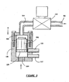
- the converter 48 may be replaced by a debubbling chamber as shown in Figure 2 which comprises a housing 100 which defines a converter chamber 102.
- the housing 100 has an inlet 104 which connects to the conduit 44 so that the bubbles in the conduit 44 can enter the inlet 104 and pass into chamber 102.
- a float 106 is located in the chamber 102 and the float 106 carries a magnet 108 on its lower side.
- a pair of proximity switches 110 and 112 are fixed to the housing 100 and are activated by the magnet 108 when the magnet 108 is moved to a position adjacent the respective switch 110 or 112.
- the chamber 102 has an outlet 114 and a solenoid valve 116 is arranged in the outlet 114 for selectively opening and closing the outlet 114.
- the outlet 114 is then connected to line 50 which is shown in Figure 1.
- Opening the valve 116 enables the vapour within the chamber 102 to pass through the valve 116 and to the vapour line 50 for return to the inlet manifold 32 and then for supply to the engine E.
- the liquid level in chamber 102 is able to rise and the float 106 is able to return to the position shown in Figure 2 and the switch 112 is deactivated.
- the magnet then is adjacent the switch 110 which then indicates a standby condition and the valve 116 is closed until the pressure again builds up to push the float 116 and magnet 108 to a position adjacent the switch 112.
- this embodiment of the invention is able to cope with the creation of bubbles which are generated when LPG is ejected under pressure from the injector 20.
- the bubbles are able to be collected and debubbled and therefore returned as fuel to the engine.
- the inlet manifold 32 is preferably cooled by a water passage or other coolant passage which extends through the inlet manifold 32. This maintains the inlet manifold 32 at a lower temperature and tends to protect the LPG fuel from the radiant heat of the engine E, thereby maintaining the LPG primarily in a liquid state.
- the cooling passages through the inlet manifold 32 may connect to a vapour converter system of the type shown in Figure 2 but which includes liquid cooling so that the cooling liquid is circulated from the vapour converter to the inlet manifold 32.
- the sensor 80 which measures the pressure in the inlet manifold 32 provides a signal to the unit 70.
- the throttle position sensor 76 and the sensor 80 are monitored by the unit 70 which in turn controls the amount of LPG liquid to be injected through the inlet manifold 32.
- Equal flushing of each injector of the engine is achieved through the first in last out principle by using equal distant path lengths from the pintle seat 30 to the vapour system 48 on each injector.
- the number of injectors for the LPG liquid injection system depends on the number of cylinders.
- the pulse width modulation for the injector which is supplied on line 86 to operate to coil 24 is controlled with reference to the engine load, RPM, temperature, inlet air temperature, fuel temperature, pressed throttle position, acceleration and deceleration transient boost air pressure, all of which are determined by the unit 70.
- the unit 70 in turn is programmed to provide, at all RPM settings, predetermined fuel quantities (diesel engines refers to the dg mixture) which are introduced in order to achieved the specified power curve, emission levels and economy.
- predetermined fuel quantities diesel engines refers to the dg mixture
- the cam angle sensor 82 provides time sequential injection. That is, when the exhaust valve is open there is no LPG present; when it is closed and the inlet valve is open LPG is introduced sequentially.
- the engine temperature is monitored to ensure that at cold temperatures the mixtures are correct as per the specifications of the unit 70 to ensure emissions controls are achieved.
- the application of the vapour from the system 48 via line 50 flushes the tip of the pintle 28 adjacent the orifice 31 and also the vicinity of the orifice 31.
- each injector 20 time sequential injection from each injector 20 is provided such that no LPG is present in scavenging air.
- the sensor 80 is designed such that the signal it provides to the engine control unit in the form of an original equipment manufacture engine control unit, is modified for controlled diesel usage reduction. The sensor can be disabled if it is desired to run the engine using diesel fuel only rather than a mixture of diesel fuel and LPG.
- the LPG is supplied in an alternative way as will be described in detail herein below.
- the slots 90 need not be provided, or if provided so that a single form of injector 20 can be used with both the embodiments of Figures 1 and 2, and 3 to 6, the slots 90 are blocked off to prevent escape of LPG from the injector body 22.
- the LPG is delivered axially through the injector body 22 as is conventional, rather than transversely as in Figure 1.
- LPG tank 12 supplies LPG via tank lock 14 to service line 16 and onto inline filter 4, the filtered LPG is then conveyed through service line 37 to distribution block 38. From the distribution block 38 the LPG liquid flows through insulated delivery lines 39 to injector housings 3 (shown in more detail in Figures 4 and 5).
- stop valve 9 When stop valve 9 is open LPG liquid and vapour bubbles flow through stop valve 9 with the liquid dropping via gravity to injector inlet 201 and the bubbles rising to converter inlet 11.
- the injector housing 3 supports the injector 20 and also acts to draw away the bubbles from the injector inlet 201.
- the injector housing 3 also provides cooling of the injector 20 so as to maintain the fuel in the injector 20 in the liquid state and thereby prevents the fuel from converting into a boiling or bubble state while in the injector 20.
- liquid at injector inlet 201 and a pulse width supplied from ECU 70 to injector 20 the liquid LPG travels through the injector 20 and is ejected into manifold 32 (see Figure 5), with the spray directed towards inlet port 29 (see Figure 5).
- the injection of the LPG is timed by the ECU 70 such that the pulse occurs after the closing of exhaust valve 133 (see Figure 5) and before the closing of the inlet valve 132 (see Figure 5), such that the downward action of piston 131 (see Figure 5) can draw into engine E all of the LPG ejected, with no blow-by past exhaust valve 33.
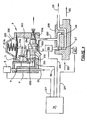
- the housing 3 has a cap portion 203a which is closed by a diaphragm 202.
- the diaphragm 202 forms one wall of the chamber 203 and the diaphragm 202 is biased inwardly of the chamber 203 by a spring 205.
- the diaphragm 202 carries a lever 206 which connects to a flat valve 207 which seals the inlet 11, dependent upon the pressure in the chamber 203.
- the injector 20 is mounted in the chamber 203 and has an inlet 201 supported on a flat 251 and its mid-portion 20a sealed in wall structure 252 and 253 of the chamber 203.
- the outlet end of the injector 20 is sealed in bore 256 in the chamber 3 which is exposed to the inlet manifold 32 of the engine E.
- the LPG supplied through the weir T piece 8 to the inlet 11 is at a significantly higher pressure than the interior of the chamber 203, which pushes the valve 207 open against the diaphragm 202 and biases the spring 205, so that bubbles and vapour which occur in the liquid supplied to the inlet 201 will rise and flow into the inlet 11 and into the chamber 203.
- the reduced pressure within the chamber 203 allows the bubbles to collapse and, with any liquid which enters the chamber 203, to turn to vapour thereby cooling the injector 20 which is exposed to the chamber 203.
- This cooling of the injector 20 ensures that the LPG which enters the inlet 201 is maintained in a liquid state because of the cold state of the injector 20, and does not convert to vapour in the injector 20, which would impair operation of the injector 20 and prevent proper ejection of fuel from the injector 20.
- the diaphragm 202 is pushed upwardly in Figure 4 against the bias of the spring 205, which causes the lever 206 to close the flat valve 207 against the inlet to prevent further entry of bubbles and vapour into the housing 203 until the pressure in the housing 203 has decreased by egress of LPG from the housing 203 via outlet conduit 209.
- the reduced pressure vapour and liquid in chamber 203 has a cooling effect on the housing 3 and injector 20.
- This cooling effect is required to reduce the likelihood of LPG vaporisation within the injection system and, in particular, in the injector 20.
- the remaining LPG enters the conduit 209 and is conveyed to a vapour block 208.
- the block 208 contains an orifice 118. This orifice 118 restricts the flow of the LPG, creating a back pressure to control the quantity of LPG vapour which enters the engine through conduit 119.
- the vapour block 208 has attached a hot water inlet 120 and a hot water outlet 121 and a bore (not shown) extends through the block 208 to heat the block so the fuel in the block 208 remains in a vapour state.
- the inlet 120 and outlet 121 are connected into the vehicle cabin heater circuit to maintain the block 208 at engine coolant temperature. Whilst the block 208 is at engine coolant temperature it is not possible for low pressure LPG to remain in liquid form, preventing an inadvertent supply of LPG through the block 208, so only vapour is supplied to the engine by the conduit 119.
- the block 208 may also be fitted with a second stage orifice 117 and an electrical solenoid valve 116 such that differing amounts of bleed vapour may be supplied to the engine by conduit 119.
- Solenoid 116 is controlled by ECU 70 through circuit 125.
- Block 208 may also contain a coolant temperature sensor 123 which feeds back engine temperature information through circuit 124 to ECU 70.
- Figures 5 and 6 also show diesel injector 171 for supplying diesel fuel to the cylinders of the engine E concurrently with the supply of LPG via the injector 20 and the conduit 19.
- the injector 20 and the conduit 119 by supplying fuel in the form of LPG from the injector 20 and the conduit 119, the amount of diesel fuel which is required can be reduced, thereby increasing fuel economy compared to situations which would occur when only diesel fuel is supplied via the diesel injector 171.
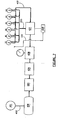
- a standard compressed natural gas tank 400 is shown being filled from a compressed natural gas filling station 401 via a line 402.
- the compressed natural gas is typically at a pressure in the order of 3000 psi in the compressed natural tank which is mounted in a vehicle.
- the compressed natural gas from the tank 400 is supplied to an air conditioner heat exchanging unit 404 for reducing the temperature of the compressed natural gas supplied from the tank to maintain the compressed natural gas in a cold state.
- the compressed natural gas is then supplied to a filter 406 for removing contaminants for unwanted substances in the compressed natural gas and the compressed natural gas is then supplied to a pressure regulator 408 for reducing the pressure of the natural gas down to about 100 psi.
- the compressed natural gas is then supplied to a heat exchanger 410 and then passes through fuel line 412 to each of the housings 3, which are the same as the housings 3 described with reference to Figures 3 to 6.
- the housings 3 contain the fuel injectors 20 also in the manner previously described, and the injectors are cooled in the same manner as previously described so that the fuel in the injectors is maintained in a liquid state for injection from the injectors. Any bubbled fuel from the housing 3 passes through the heat exchanger 410 in conduit 209 to provide heat exchange with the fuel in the line 412 for assisting in maintaining the fuel in the line 412 cool.
- the line 209 then connects to a vapour block 208 which is the same as the vapour block 208 previously described. Vapour fuel leaves the vapour block via conduit 119 for delivery to the air intake of the engine in the same manner as previously described.
- the liquid gas fuel used in the fuel delivery system for powering the internal combustion engine may be comprised of liquefied petroleum gas and methanol/ethanol mixture in any ratio, or liquefied petroleum gas, methanol/ethanol and water in any ratio.
- the liquid gas fuel may comprise an alcohol such as methanol or ethanol, mixed with a liquid hydrocarbon that vaporises readily at standard temperature and pressure such as butane or propane.
- the fuel may include additional water to any water which is already present in the alcohol included in the fuel.
Landscapes
- Engineering & Computer Science (AREA)
- Chemical & Material Sciences (AREA)
- Combustion & Propulsion (AREA)
- Mechanical Engineering (AREA)
- General Engineering & Computer Science (AREA)
- Oil, Petroleum & Natural Gas (AREA)
- Chemical Kinetics & Catalysis (AREA)
- General Chemical & Material Sciences (AREA)
- Organic Chemistry (AREA)
- Fuel-Injection Apparatus (AREA)
- Output Control And Ontrol Of Special Type Engine (AREA)
- Jet Pumps And Other Pumps (AREA)
- Lubrication Of Internal Combustion Engines (AREA)
- Feeding, Discharge, Calcimining, Fusing, And Gas-Generation Devices (AREA)
Claims (7)
- Kraftstoffzufuhrsystem für einen Motor, das Folgendes umfasst:ein erstes Kraftstoffzufuhrmittel, das zum Zuführen eines ersten Kraftstoffes zum Motor dient, wobei der erste Kraftstoff ein Dieselkraftstoff ist; undein zweites Kraftstoffzufuhrmittel, das zum Zuführen eines zweiten Kraftstoffes von einem Vorratsbehälter (12) zum Motor dient, und zwar gleichzeitig mit dem ersten Kraftstoff;wobei das zweite Kraftstoffzufuhrmittel Folgendes umfasst:ein Einspritzventil (20) zum Ausstoßen des zweiten Kraftstoffes in den Motor;Steuerungsmittel (70) zum Steuern des Einspritzventils (20); undeine Einlassleitung (16) für die Kommunikation zwischen dem Vorratsbehälter (12) und dem Einspritzventil (20);dadurch gekennzeichnet, dass:der zweite Kraftstoff ein Flüssiggaskraftstoff ist, der den Vorratsbehälter (12) in einem flüssigen Zustand verlässt;das zweite Kraftstoffzufuhrmittel ein Aufrechterhaltungsmittel zum Aufrechterhalten der Temperatur und des Drucks des zweiten Kraftstoffes in der Einlassleitung (16) so umfasst, dass er mindestens teilweise im flüssigen Zustand bleibt; unddas zweite Kraftstoffzufuhrmittel ein Verhinderungsmittel zum Verhindern der Verdampfung und der Blasenbildung des zweiten Kraftstoffes im Einspritzventil (20) so umfasst, dass der zweite Kraftstoff vom Einspritzventil (20) im flüssigen Zustand ausgestoßen wird.
- Kraftstoffzufuhrsystem nach Anspruch 1, bei dem das Einspritzventil (20) den zweiten Kraftstoff in den Einlasskrümmer des Motors einspritzt.
- Kraftstoffzufuhrsystem nach Anspruch 2, bei dem das erste Kraftstoffzufuhrmittel dem Einlasskrümmer des Motors oder einem Zylinder des Motors den ersten Kraftstoff zuführt.
- Kraftstoffzufuhrsystem nach Anspruch 1, bei dem das Einspritzventil (20) ein Einspritzventilgehäuse (252, 253) und einen Einspritzventilkörper (20a) im Gehäuse umfasst.
- Kraftstoffzufuhrsystem nach Anspruch 1, bei dem das Verhinderungsmittel ein Kraftstoffblasen-Sammelsystem (208) umfasst, das Folgendes umfasst:Mittel (209) zum Sammeln der Dampfblasen vom zweiten Kraftstoff, die erzeugt werden, wenn der zweite Kraftstoff dem Einspritzventil (20) zugeführt wird;ein System (117, 118, 208), das zur Aufnahme der Blasen und zu ihrer Umwandlung in Dampf dient; undeine Leitung (119), die zum Zuführen des Dampfes zum Motor dient.
- Kraftstoffzufuhrsystem nach Anspruch 1, bei dem das Steuerungsmittel (70) Informationen von einem oder mehreren der folgenden Mittel erhält:Temperatur-Erfassungsmittel (72) zum Erfassen der Temperatur des zweiten Kraftstoffes, der der Einlassleitung (16) zugeführt wird;Druck-Erfassungsmittel (74) zum Erfassen des Drucks des zweiten Kraftstoffes, der dem Einspritzventil (20) zugeführt wird;Motortemperatur-Erfassungsmittel zum Erfassen der Temperatur des Motors;Lufttemperatur-Erfassungsmittel (78) zum Erfassen der Temperatur der Luft, die dem Motor über einen Lufteinlass zugeführt wird;Drosselklappenstellungs-Erfassungsmittel (76) zum Erfassen der Stellung eines Gaspedals;Nockenwinkel-Erfassungsmittel (82) zum Erfassen der Stellung eines Nockens des Motors; undMotoreinlassdruck-Erfassungsmittel (80) zum Erfassen des Einlassluftdrucks am Motor.
- Kraftstoffzufuhrsystem nach Anspruch 1, bei dem das Verhinderungsmittel Folgendes umfasst:ein Gehäuse (3) zur Aufnahme des zweiten Kraftstoffes von der Einlassleitung (16);wobei das Einspritzventil (20) in das Gehäuse (3) eingebaut ist und einen Kraftstoffeinlass aufweist, damit der zweite Kraftstoff in das Einspritzventil eintreten kann, sowie einen Flüssigkraftstoffauslass, um den zweiten Kraftstoff in dem flüssigen Zustand vom Einspritzventil aus an den (die) Zylinder des Motors auszustoßen;eine Kammer (203) im Gehäuse (3), die mindestens teilweise das Einspritzventil (20) umgibt, um auch den zweiten Kraftstoff aufzunehmen, damit der zweite Kraftstoff das Einspritzventil (20) umgeben kann, um das Einspritzventil zu kühlen, damit der aus dem Einspritzventil auszustoßende zweite Kraftstoff im Einspritzventil in einem flüssigen Zustand gehalten wird;einen Auslass (209) an der Kammer (203), damit Dampf und jede in der Kammer (203) vorhandene Flüssigkeit aus der Kammer (203) austreten kann;einen Druckregler (202-207) zum Regulieren des Druckes des Dampfes und der Flüssigkeit in der Kammer (203), um die Kühlung des Einspritzventils durch die Verdampfung der Flüssigkeit in der Kammer (203) aufrechtzuerhalten;eine Verdampfungseinrichtung (208), die mit dem Auslass (209) verbunden ist, um den Dampf von der Kammer (203) in einem dampfförmigen Zustand zu halten und um jede von der Kammer (203) aufgenommene Flüssigkeit in den dampfförmigen Zustand zu überführen; undeine Dampfzufuhreinrichtung (119), die dem (den) Zylinder(n) des Motors den Dampf zuführt.
Applications Claiming Priority (9)
| Application Number | Priority Date | Filing Date | Title |
|---|---|---|---|
| AUPR4344A AUPR434401A0 (en) | 2001-04-09 | 2001-04-09 | Fuel delivery system |
| AUPR5774A AUPR577401A0 (en) | 2001-06-19 | 2001-06-19 | Fuel delivery system |
| AUPR5879A AUPR587901A0 (en) | 2001-06-21 | 2001-06-21 | Fuel delivery system |
| AUPR763801 | 2001-09-13 | ||
| AUPR8791A AUPR879101A0 (en) | 2001-11-09 | 2001-11-09 | Fuel delivery system |
| AUPR9758A AUPR975801A0 (en) | 2001-12-24 | 2001-12-24 | Fuel delivery system |
| AUPS0310A AUPS031002A0 (en) | 2002-02-04 | 2002-02-04 | Fuel delivery system |
| AUPS0623A AUPS062302A0 (en) | 2002-02-18 | 2002-02-18 | Fuel delivery system |
| EP02713938A EP1377739B1 (de) | 2001-04-09 | 2002-04-09 | Kraftstoffzufuhrsystem |
Related Parent Applications (1)
| Application Number | Title | Priority Date | Filing Date |
|---|---|---|---|
| EP02713938A Division EP1377739B1 (de) | 2001-04-09 | 2002-04-09 | Kraftstoffzufuhrsystem |
Publications (2)
| Publication Number | Publication Date |
|---|---|
| EP1619378A1 EP1619378A1 (de) | 2006-01-25 |
| EP1619378B1 true EP1619378B1 (de) | 2007-05-30 |
Family
ID=27570139
Family Applications (2)
| Application Number | Title | Priority Date | Filing Date |
|---|---|---|---|
| EP05018664A Expired - Lifetime EP1619378B1 (de) | 2001-04-09 | 2002-04-09 | Kraftstoffzufuhrsystem |
| EP02713938A Expired - Lifetime EP1377739B1 (de) | 2001-04-09 | 2002-04-09 | Kraftstoffzufuhrsystem |
Family Applications After (1)
| Application Number | Title | Priority Date | Filing Date |
|---|---|---|---|
| EP02713938A Expired - Lifetime EP1377739B1 (de) | 2001-04-09 | 2002-04-09 | Kraftstoffzufuhrsystem |
Country Status (14)
| Country | Link |
|---|---|
| US (1) | US7207321B2 (de) |
| EP (2) | EP1619378B1 (de) |
| JP (2) | JP2004528508A (de) |
| KR (4) | KR100851389B1 (de) |
| CN (1) | CN100365258C (de) |
| AT (2) | ATE363592T1 (de) |
| AU (1) | AU2002245945B2 (de) |
| BR (1) | BR0208902A (de) |
| CA (1) | CA2443435C (de) |
| DE (2) | DE60220456T2 (de) |
| ES (2) | ES2287848T3 (de) |
| NZ (1) | NZ528422A (de) |
| PT (1) | PT1619378E (de) |
| WO (1) | WO2002081895A1 (de) |
Families Citing this family (33)
| Publication number | Priority date | Publication date | Assignee | Title |
|---|---|---|---|---|
| GB0205062D0 (en) | 2002-03-05 | 2002-04-17 | Autogas Supplies Ltd | Dual fuel engine |
| AU2003290494B2 (en) * | 2002-08-23 | 2008-08-28 | James Richard Hunt | Fuel delivery system |
| AU2002950972A0 (en) | 2002-08-23 | 2002-09-12 | Hunt, James Richard | Fuel delivery system |
| DE102004019630A1 (de) * | 2004-04-22 | 2005-11-17 | Wacker Construction Equipment Ag | Ölversorgung für einen Verbrennungsmotor |
| DE102006056389A1 (de) * | 2006-11-29 | 2008-06-05 | Audi Ag | Betriebsverfahren für eine wahlweise mit flüssigem und gasförmigem Kraftstoff betreibbare Brennkraftmaschine und Kraftstoffzuführsystem |
| US9121372B2 (en) * | 2007-02-06 | 2015-09-01 | Bernardo J. Herzer | Portable gas powered internal combustion engine arrangement |
| DE102007022230A1 (de) | 2007-05-09 | 2008-11-13 | Ecomotec Gmbh | Vorrichtung zum Steuern eines Selbstzünder-Verbrennungsmotors im Zweistoffbetrieb sowie Verfahren zum Betreiben desselben |
| DE102007057298A1 (de) * | 2007-11-28 | 2009-06-04 | Volkswagen Ag | Brennkraftmaschine und Verfahren zum Betreiben dieser |
| JP2012524207A (ja) * | 2009-04-20 | 2012-10-11 | ディージーシー インダストリーズ ピーティーワイ リミテッド | ディーゼルエンジンの間接噴射システム用のデュアルフューエル供給システム |
| EP2585697A4 (de) * | 2009-06-23 | 2014-03-05 | Anthony James Horley | System und verfahren zur einspritzung von brenngas in flüssiger form in einen dieselmotor |
| US8516997B2 (en) * | 2010-05-28 | 2013-08-27 | Ford Global Technologies, Llc | Approach for controlling fuel flow with alternative fuels |
| AU2011274314B2 (en) * | 2010-06-30 | 2014-08-07 | Orbital Australia Pty Ltd | Fuel injector icing |
| WO2012021709A1 (en) | 2010-08-11 | 2012-02-16 | Cummins Intellectual Properties, Inc | Engine with injector mounting and cooling arrangement |
| ES2402247B1 (es) * | 2010-09-20 | 2014-04-08 | Repsol, S.A | Formulación, preparación y uso de glp con contenido renovable |
| CN102618334B (zh) * | 2012-02-09 | 2014-04-09 | 白玉堂 | 柴油机液体增压剂及专用汽化器 |
| US9188084B2 (en) | 2012-10-31 | 2015-11-17 | Electro-Motive Diesel, Inc. | Fuel system having a cooled injector |
| US9188085B2 (en) | 2012-10-31 | 2015-11-17 | Electro-Motive Diesel, Inc. | Fuel system having multiple gaseous fuel injectors |
| US9046068B2 (en) | 2012-10-31 | 2015-06-02 | Electro-Motive Diesel, Inc. | Fuel system for a dual-fuel engine |
| US9500168B2 (en) | 2012-10-31 | 2016-11-22 | Electro-Motive Diesel, Inc. | Fuel system having a fuel-cooled injector |
| US9334813B2 (en) | 2013-01-31 | 2016-05-10 | Electro-Motive Diesel, Inc. | Control system for a dual-fuel engine |
| US9441529B2 (en) | 2013-06-27 | 2016-09-13 | Electro-Motive Diesel, Inc. | Fuel system having sealed injection port |
| CN103953457B (zh) * | 2014-03-21 | 2015-06-17 | 哈尔滨工程大学 | 一种船用柴油-lng双燃料发动机多级交叉换热装置 |
| DE102014212317A1 (de) * | 2014-06-26 | 2015-12-31 | Robert Bosch Gmbh | Verfahren und Steuerung zur Einstellung der Verbrennungsparameter bei einer mit Flüssigerdgas betriebenen Brennkraftmaschine |
| CN105508063A (zh) * | 2014-09-25 | 2016-04-20 | 陕西汽车集团有限责任公司 | 车用天然气甲醇混燃系统、发动机系统及车辆 |
| JP6398881B2 (ja) | 2015-06-09 | 2018-10-03 | 株式会社デンソー | 燃料噴射装置 |
| CN106321306A (zh) * | 2015-06-18 | 2017-01-11 | 绍兴文理学院 | 一种矿用车发动机电控喷射装置 |
| CN107035550A (zh) * | 2015-07-30 | 2017-08-11 | 马耀辉 | 一种柴油机燃油转换自动调配器 |
| GB2563928B (en) * | 2017-06-30 | 2019-11-13 | Ricardo Uk Ltd | Injector |
| DE102018200405B4 (de) * | 2018-01-11 | 2022-12-29 | Ford Global Technologies, Llc | Vorrichtung zur Schmierstoffbereitstellung |
| CN113457869B (zh) * | 2021-09-01 | 2021-11-16 | 苏州好博医疗器械股份有限公司 | 一种蒸汽喷射设备的喷头保护装置 |
| GB2622016B (en) * | 2022-08-30 | 2025-04-02 | Phinia Delphi Luxembourg Sarl | Lubricant dosing device for gaseous fuel engine |
| JP2025031103A (ja) * | 2023-08-25 | 2025-03-07 | トヨタ自動車株式会社 | 内燃機関の制御装置 |
| US12510034B2 (en) * | 2024-01-23 | 2025-12-30 | Blossman Services, Inc. | Dual liquefied petroleum gas vapor and liquid injection system and method of control |
Family Cites Families (39)
| Publication number | Priority date | Publication date | Assignee | Title |
|---|---|---|---|---|
| US4503826A (en) * | 1981-04-22 | 1985-03-12 | General Motors Corporation | Fuel injection apparatus |
| US4416244A (en) * | 1981-12-24 | 1983-11-22 | Cummins Engine Company, Inc. | Control system for a dual fuel internal combustion engine |
| NL8200993A (nl) * | 1982-03-10 | 1983-10-03 | Calcol B V | Inrichting voor injectie van brandstof, zoals lpg, in vloeibare vorm. |
| US4463734A (en) | 1982-05-14 | 1984-08-07 | Akeroyd Richard T | Dual fuel diesel engine |
| NZ205140A (en) * | 1983-08-04 | 1987-02-20 | H M Reid | Electronically controlled dual fuel system for diesel engines |
| JPH0517414Y2 (de) * | 1986-03-12 | 1993-05-11 | ||
| WO1989000640A1 (en) * | 1987-07-10 | 1989-01-26 | Gaspower Limited | Improvements in or relating to fuel injection |
| EP0387288A4 (en) * | 1987-11-25 | 1990-11-07 | Gas Outboards International Pty. Ltd. | Fuel injector |
| US4865001A (en) | 1988-11-28 | 1989-09-12 | Energy Conversions, Inc. | Gaseous fuel injector valve |
| DE3907972A1 (de) * | 1989-03-11 | 1990-09-13 | Bosch Gmbh Robert | Kraftstoffeinspritzsystem fuer brennkraftmaschinen |
| US5140965A (en) | 1990-04-17 | 1992-08-25 | Hitachi, Ltd. | System for and method of supplying fuel to internal combustion engine |
| US5033444A (en) | 1990-09-04 | 1991-07-23 | Kaufman Ray L | Liquid butane fuel injection for internal combustion engines |
| JP2688572B2 (ja) * | 1991-01-16 | 1997-12-10 | 工業技術院長 | デュアルフューエル・ディーゼル機関のlpガス供給方法 |
| US5287281A (en) | 1991-02-27 | 1994-02-15 | Echlin Inc. | Computer controlled flow of nitrous oxide injected into an internal combustion engine |
| US5291869A (en) * | 1993-05-28 | 1994-03-08 | Bennett David E | Liquified petroleum gas fuel supply system |
| US5325838A (en) | 1993-05-28 | 1994-07-05 | Bennett David E | Liquified petroleum gas fuel injector |
| US5423303A (en) * | 1993-05-28 | 1995-06-13 | Bennett; David E. | Fuel rail for internal combustion engine |
| AUPM632494A0 (en) * | 1994-06-21 | 1994-07-14 | Biocom Pty Ltd | Auxiliary injector |
| JPH08189434A (ja) * | 1995-01-12 | 1996-07-23 | Toyota Motor Corp | 内燃機関の燃料供給装置 |
| AU703827B2 (en) * | 1995-01-13 | 1999-04-01 | Gas Injection Technologies Pty Limited | Liquefied petroleum gas injection apparatus |
| US5947385A (en) * | 1996-04-19 | 1999-09-07 | Graco Inc. | Vehicle towed apparatus for striping of roads |
| US5673668A (en) | 1996-08-05 | 1997-10-07 | Ford Global Technologies, Inc. | Method and apparatus for electronic throttle monitoring |
| EP0826872A3 (de) * | 1996-08-26 | 1999-11-24 | Yamaha Hatsudoki Kabushiki Kaisha | Flüssigkeitseinspritzvorrichtung |
| US5823446A (en) * | 1997-02-18 | 1998-10-20 | Awalbro Corporation | Fuel injector valve for liquified fuel |
| JPH1136990A (ja) * | 1997-07-18 | 1999-02-09 | Nippon Soken Inc | エンジンの燃料供給装置 |
| JPH11210557A (ja) * | 1998-01-30 | 1999-08-03 | Aisan Ind Co Ltd | エンジンの液化ガス燃料供給装置 |
| WO1999045262A1 (en) * | 1998-03-04 | 1999-09-10 | Vialle Beheer B.V. | Fuel injection drive for an internal combustion engine |
| JPH11294212A (ja) * | 1998-04-03 | 1999-10-26 | Toyota Motor Corp | バイフューエル内燃機関の供給燃料制御装置 |
| US6032617A (en) * | 1998-05-27 | 2000-03-07 | Caterpillar Inc. | Dual fuel engine which ignites a homogeneous mixture of gaseous fuel, air, and pilot fuel |
| JP4063409B2 (ja) * | 1998-07-23 | 2008-03-19 | 東京瓦斯株式会社 | デュアルフューエルエンジンの運転装置 |
| JP2000130279A (ja) * | 1998-10-21 | 2000-05-09 | Toyota Motor Corp | 内燃機関の高圧燃料供給装置 |
| CN1266885A (zh) * | 1999-03-12 | 2000-09-20 | 孟贺天 | 节能金属焊割气 |
| CN1267713A (zh) * | 1999-03-23 | 2000-09-27 | 赵海桥 | 一种焊割混和燃气及其该燃气的制备方法 |
| CN1288940A (zh) * | 1999-09-17 | 2001-03-28 | 陈鸿林 | 高燃值的可燃气体 |
| AUPQ392999A0 (en) | 1999-11-09 | 1999-12-02 | Sangster, Timothy James | Liquid fuel vapourisation apparatus for fuel injected internal combustion engines |
| JP3483509B2 (ja) * | 1999-12-13 | 2004-01-06 | トヨタ自動車株式会社 | 内燃機関の燃料噴射システム |
| CN1316489A (zh) * | 2000-04-04 | 2001-10-10 | 卢友明 | 高能合成液化气制配方法 |
| AU2001261245A1 (en) | 2000-05-08 | 2001-11-20 | Cummins, Inc. | Multiple operating mode engine and method of operation |
| GB0205062D0 (en) | 2002-03-05 | 2002-04-17 | Autogas Supplies Ltd | Dual fuel engine |
-
2002
- 2002-04-09 US US10/474,316 patent/US7207321B2/en not_active Expired - Fee Related
- 2002-04-09 CA CA002443435A patent/CA2443435C/en not_active Expired - Fee Related
- 2002-04-09 ES ES05018664T patent/ES2287848T3/es not_active Expired - Lifetime
- 2002-04-09 BR BR0208902-5A patent/BR0208902A/pt not_active Application Discontinuation
- 2002-04-09 KR KR1020037013173A patent/KR100851389B1/ko not_active Expired - Fee Related
- 2002-04-09 WO PCT/AU2002/000453 patent/WO2002081895A1/en not_active Ceased
- 2002-04-09 EP EP05018664A patent/EP1619378B1/de not_active Expired - Lifetime
- 2002-04-09 KR KR1020087004108A patent/KR100912709B1/ko not_active Expired - Fee Related
- 2002-04-09 JP JP2002579639A patent/JP2004528508A/ja active Pending
- 2002-04-09 EP EP02713938A patent/EP1377739B1/de not_active Expired - Lifetime
- 2002-04-09 AT AT05018664T patent/ATE363592T1/de not_active IP Right Cessation
- 2002-04-09 DE DE60220456T patent/DE60220456T2/de not_active Expired - Fee Related
- 2002-04-09 ES ES02713938T patent/ES2257535T3/es not_active Expired - Lifetime
- 2002-04-09 AT AT02713938T patent/ATE314567T1/de not_active IP Right Cessation
- 2002-04-09 KR KR1020087008205A patent/KR100876390B1/ko not_active Expired - Fee Related
- 2002-04-09 CN CNB028115910A patent/CN100365258C/zh not_active Expired - Fee Related
- 2002-04-09 DE DE60208356T patent/DE60208356T2/de not_active Expired - Fee Related
- 2002-04-09 AU AU2002245945A patent/AU2002245945B2/en not_active Ceased
- 2002-04-09 KR KR1020087008203A patent/KR100876391B1/ko not_active Expired - Fee Related
- 2002-04-09 NZ NZ528422A patent/NZ528422A/en unknown
- 2002-04-09 PT PT05018664T patent/PT1619378E/pt unknown
-
2008
- 2008-04-10 JP JP2008102143A patent/JP2008261336A/ja active Pending
Non-Patent Citations (1)
| Title |
|---|
| None * |
Also Published As
Similar Documents
| Publication | Publication Date | Title |
|---|---|---|
| EP1619378B1 (de) | Kraftstoffzufuhrsystem | |
| AU2002245945A1 (en) | Fuel delivery system | |
| CA2124534C (en) | Liquified petroleum gas fuel supply system | |
| US7506638B2 (en) | Fuel delivery system | |
| US5408957A (en) | Continuous combustible gas injection into conventionally fueled internal combustion engines | |
| US4373493A (en) | Method and apparatus for utilizing gaseous and liquid fuels in an internal combustion engine | |
| EP0676005A1 (de) | Verfahren und vorrichtung zur verwendung von gasförmigen und flüssigen kraftstoffen in einer brennkraftmaschine | |
| CN101196147A (zh) | 内燃机的运行方法及燃料供给系统 | |
| CN204458139U (zh) | 燃料系统 | |
| US7047947B2 (en) | LPG vehicular liquid transfer system | |
| US6758194B2 (en) | Parallel vaporized fuel system | |
| US6843236B1 (en) | Multi-phase fuel system | |
| ZA200307491B (en) | Fuel delivery system. | |
| AU2005211674B2 (en) | Fuel delivery system | |
| HK1105443B (en) | Fuel delivery system for engine | |
| RU2295054C2 (ru) | Система подачи топлива | |
| KR20090028772A (ko) | 내연 기관의 성능 향상 시스템 및 방법 | |
| WO1995012066A1 (en) | Engine fuel metering and steam reformer system |
Legal Events
| Date | Code | Title | Description |
|---|---|---|---|
| PUAI | Public reference made under article 153(3) epc to a published international application that has entered the european phase |
Free format text: ORIGINAL CODE: 0009012 |
|
| AC | Divisional application: reference to earlier application |
Ref document number: 1377739 Country of ref document: EP Kind code of ref document: P |
|
| AK | Designated contracting states |
Kind code of ref document: A1 Designated state(s): AT BE CH CY DE DK ES FI FR GB GR IE IT LI LU MC NL PT SE TR |
|
| AX | Request for extension of the european patent |
Extension state: AL LT LV MK RO SI |
|
| 17P | Request for examination filed |
Effective date: 20060208 |
|
| RIN1 | Information on inventor provided before grant (corrected) |
Inventor name: SHINKARENKO, ANDREI VADIMOVITCH Inventor name: HUNT, JAMES RICHARD |
|
| AKX | Designation fees paid |
Designated state(s): AT BE CH CY DE DK ES FI FR GB GR IE IT LI LU MC NL PT SE TR |
|
| GRAP | Despatch of communication of intention to grant a patent |
Free format text: ORIGINAL CODE: EPIDOSNIGR1 |
|
| RAP1 | Party data changed (applicant data changed or rights of an application transferred) |
Owner name: SHINKARENKO, ANDREI VADIMOVITCH Owner name: HUNT, JAMES RICHARD Owner name: TURNER, GEOFFREY RUSSELL |
|
| GRAS | Grant fee paid |
Free format text: ORIGINAL CODE: EPIDOSNIGR3 |
|
| GRAA | (expected) grant |
Free format text: ORIGINAL CODE: 0009210 |
|
| AC | Divisional application: reference to earlier application |
Ref document number: 1377739 Country of ref document: EP Kind code of ref document: P |
|
| AK | Designated contracting states |
Kind code of ref document: B1 Designated state(s): AT BE CH CY DE DK ES FI FR GB GR IE IT LI LU MC NL PT SE TR |
|
| PG25 | Lapsed in a contracting state [announced via postgrant information from national office to epo] |
Ref country code: FI Free format text: LAPSE BECAUSE OF FAILURE TO SUBMIT A TRANSLATION OF THE DESCRIPTION OR TO PAY THE FEE WITHIN THE PRESCRIBED TIME-LIMIT Effective date: 20070530 |
|
| REG | Reference to a national code |
Ref country code: GB Ref legal event code: FG4D |
|
| REG | Reference to a national code |
Ref country code: CH Ref legal event code: EP |
|
| REG | Reference to a national code |
Ref country code: IE Ref legal event code: FG4D |
|
| REF | Corresponds to: |
Ref document number: 60220456 Country of ref document: DE Date of ref document: 20070712 Kind code of ref document: P |
|
| REG | Reference to a national code |
Ref country code: PT Ref legal event code: SC4A Free format text: AVAILABILITY OF NATIONAL TRANSLATION Effective date: 20070824 |
|
| REG | Reference to a national code |
Ref country code: SE Ref legal event code: TRGR |
|
| ET | Fr: translation filed | ||
| PG25 | Lapsed in a contracting state [announced via postgrant information from national office to epo] |
Ref country code: AT Free format text: LAPSE BECAUSE OF FAILURE TO SUBMIT A TRANSLATION OF THE DESCRIPTION OR TO PAY THE FEE WITHIN THE PRESCRIBED TIME-LIMIT Effective date: 20070530 |
|
| NLV1 | Nl: lapsed or annulled due to failure to fulfill the requirements of art. 29p and 29m of the patents act | ||
| REG | Reference to a national code |
Ref country code: ES Ref legal event code: FG2A Ref document number: 2287848 Country of ref document: ES Kind code of ref document: T3 |
|
| REG | Reference to a national code |
Ref country code: CH Ref legal event code: NV Representative=s name: FREI PATENTANWALTSBUERO AG |
|
| PG25 | Lapsed in a contracting state [announced via postgrant information from national office to epo] |
Ref country code: DK Free format text: LAPSE BECAUSE OF FAILURE TO SUBMIT A TRANSLATION OF THE DESCRIPTION OR TO PAY THE FEE WITHIN THE PRESCRIBED TIME-LIMIT Effective date: 20070530 Ref country code: NL Free format text: LAPSE BECAUSE OF FAILURE TO SUBMIT A TRANSLATION OF THE DESCRIPTION OR TO PAY THE FEE WITHIN THE PRESCRIBED TIME-LIMIT Effective date: 20070530 |
|
| PLBE | No opposition filed within time limit |
Free format text: ORIGINAL CODE: 0009261 |
|
| STAA | Information on the status of an ep patent application or granted ep patent |
Free format text: STATUS: NO OPPOSITION FILED WITHIN TIME LIMIT |
|
| PG25 | Lapsed in a contracting state [announced via postgrant information from national office to epo] |
Ref country code: GR Free format text: LAPSE BECAUSE OF FAILURE TO SUBMIT A TRANSLATION OF THE DESCRIPTION OR TO PAY THE FEE WITHIN THE PRESCRIBED TIME-LIMIT Effective date: 20070831 |
|
| 26N | No opposition filed |
Effective date: 20080303 |
|
| PG25 | Lapsed in a contracting state [announced via postgrant information from national office to epo] |
Ref country code: MC Free format text: LAPSE BECAUSE OF NON-PAYMENT OF DUE FEES Effective date: 20080430 |
|
| PGFP | Annual fee paid to national office [announced via postgrant information from national office to epo] |
Ref country code: PT Payment date: 20081022 Year of fee payment: 8 |
|
| PG25 | Lapsed in a contracting state [announced via postgrant information from national office to epo] |
Ref country code: IE Free format text: LAPSE BECAUSE OF NON-PAYMENT OF DUE FEES Effective date: 20080409 |
|
| PGFP | Annual fee paid to national office [announced via postgrant information from national office to epo] |
Ref country code: ES Payment date: 20090324 Year of fee payment: 8 |
|
| PGFP | Annual fee paid to national office [announced via postgrant information from national office to epo] |
Ref country code: CH Payment date: 20090317 Year of fee payment: 8 |
|
| PG25 | Lapsed in a contracting state [announced via postgrant information from national office to epo] |
Ref country code: CY Free format text: LAPSE BECAUSE OF FAILURE TO SUBMIT A TRANSLATION OF THE DESCRIPTION OR TO PAY THE FEE WITHIN THE PRESCRIBED TIME-LIMIT Effective date: 20070530 |
|
| PGFP | Annual fee paid to national office [announced via postgrant information from national office to epo] |
Ref country code: DE Payment date: 20090529 Year of fee payment: 8 Ref country code: FR Payment date: 20090330 Year of fee payment: 8 Ref country code: IT Payment date: 20090326 Year of fee payment: 8 Ref country code: SE Payment date: 20090424 Year of fee payment: 8 |
|
| PGFP | Annual fee paid to national office [announced via postgrant information from national office to epo] |
Ref country code: BE Payment date: 20090427 Year of fee payment: 8 |
|
| PGFP | Annual fee paid to national office [announced via postgrant information from national office to epo] |
Ref country code: GB Payment date: 20090408 Year of fee payment: 8 |
|
| PG25 | Lapsed in a contracting state [announced via postgrant information from national office to epo] |
Ref country code: LU Free format text: LAPSE BECAUSE OF NON-PAYMENT OF DUE FEES Effective date: 20080409 |
|
| PG25 | Lapsed in a contracting state [announced via postgrant information from national office to epo] |
Ref country code: TR Free format text: LAPSE BECAUSE OF FAILURE TO SUBMIT A TRANSLATION OF THE DESCRIPTION OR TO PAY THE FEE WITHIN THE PRESCRIBED TIME-LIMIT Effective date: 20070530 |
|
| BERE | Be: lapsed |
Owner name: SHINKARENKO, ANDREI VADIMOVITCH Effective date: 20100430 Owner name: TURNER, GEOFFREY RUSSELL Effective date: 20100430 Owner name: HUNT, JAMES RICHARD Effective date: 20100430 |
|
| EUG | Se: european patent has lapsed | ||
| REG | Reference to a national code |
Ref country code: CH Ref legal event code: PL |
|
| GBPC | Gb: european patent ceased through non-payment of renewal fee |
Effective date: 20100409 |
|
| REG | Reference to a national code |
Ref country code: FR Ref legal event code: ST Effective date: 20101230 |
|
| PG25 | Lapsed in a contracting state [announced via postgrant information from national office to epo] |
Ref country code: LI Free format text: LAPSE BECAUSE OF NON-PAYMENT OF DUE FEES Effective date: 20100430 Ref country code: DE Free format text: LAPSE BECAUSE OF NON-PAYMENT OF DUE FEES Effective date: 20101103 Ref country code: CH Free format text: LAPSE BECAUSE OF NON-PAYMENT OF DUE FEES Effective date: 20100430 Ref country code: PT Free format text: LAPSE BECAUSE OF NON-PAYMENT OF DUE FEES Effective date: 20101011 |
|
| PG25 | Lapsed in a contracting state [announced via postgrant information from national office to epo] |
Ref country code: IT Free format text: LAPSE BECAUSE OF NON-PAYMENT OF DUE FEES Effective date: 20100409 Ref country code: BE Free format text: LAPSE BECAUSE OF NON-PAYMENT OF DUE FEES Effective date: 20100430 Ref country code: GB Free format text: LAPSE BECAUSE OF NON-PAYMENT OF DUE FEES Effective date: 20100409 |
|
| REG | Reference to a national code |
Ref country code: ES Ref legal event code: FD2A Effective date: 20110714 |
|
| PG25 | Lapsed in a contracting state [announced via postgrant information from national office to epo] |
Ref country code: ES Free format text: LAPSE BECAUSE OF NON-PAYMENT OF DUE FEES Effective date: 20110704 |
|
| PG25 | Lapsed in a contracting state [announced via postgrant information from national office to epo] |
Ref country code: ES Free format text: LAPSE BECAUSE OF NON-PAYMENT OF DUE FEES Effective date: 20100410 |
|
| PG25 | Lapsed in a contracting state [announced via postgrant information from national office to epo] |
Ref country code: FR Free format text: LAPSE BECAUSE OF NON-PAYMENT OF DUE FEES Effective date: 20100430 |
|
| PG25 | Lapsed in a contracting state [announced via postgrant information from national office to epo] |
Ref country code: SE Free format text: LAPSE BECAUSE OF NON-PAYMENT OF DUE FEES Effective date: 20100410 |