EP1617155A1 - Lüftungsgitter - Google Patents
Lüftungsgitter Download PDFInfo
- Publication number
- EP1617155A1 EP1617155A1 EP05106373A EP05106373A EP1617155A1 EP 1617155 A1 EP1617155 A1 EP 1617155A1 EP 05106373 A EP05106373 A EP 05106373A EP 05106373 A EP05106373 A EP 05106373A EP 1617155 A1 EP1617155 A1 EP 1617155A1
- Authority
- EP
- European Patent Office
- Prior art keywords
- vertical
- rail
- frame
- profiles
- uprights
- Prior art date
- Legal status (The legal status is an assumption and is not a legal conclusion. Google has not performed a legal analysis and makes no representation as to the accuracy of the status listed.)
- Granted
Links
Images


Classifications
-
- F—MECHANICAL ENGINEERING; LIGHTING; HEATING; WEAPONS; BLASTING
- F24—HEATING; RANGES; VENTILATING
- F24F—AIR-CONDITIONING; AIR-HUMIDIFICATION; VENTILATION; USE OF AIR CURRENTS FOR SCREENING
- F24F13/00—Details common to, or for air-conditioning, air-humidification, ventilation or use of air currents for screening
- F24F13/08—Air-flow control members, e.g. louvres, grilles, flaps or guide plates
- F24F13/082—Grilles, registers or guards
Definitions
- the present invention relates to a ventilation grille using a blade attachment system for mounting side by side of the blades so as to produce a perforated structure.
- the blades are attached parallel to each other at an angle to the wall on which they are installed.
- Such blades are used to form ventilation grids closing a bay in a wall or for making walls of buildings.
- the blades are held on a fastening system inside a frame mounted in the bay while in the case of a wall cladding, the blades are put in place on the system. fastened and placed end to end to cover the wall.
- document GB-2 300 473 which describes a ventilation grid comprising a frame, stiffening profiles, blade support elements and blades.
- the blades are fixed or mounted on the blade support members which comprise a sole engaged in a vertical longitudinal rail formed by the vertical stiffening profiles.
- the vertical stiffening profiles are fixed at each of their ends to the frame, and more particularly to the horizontal cross members of the frame.
- the blade support members are held in place in the rail of the stiffening profile by stacking the blade support members in the rail. Thus, each blade support member abuts the lower adjacent blade support member. Since the blade support members are slidably inserted into the rail, there is necessarily a gap between the blade support members and the rail. The maintenance of the elements of blade support in the rail is therefore not stable and can therefore generate very annoying structural noise.
- EP-0 770 832 discloses a modular grid comprising a frame, blade support members and blades.
- the frame forms a rail in which the blade support members are slidably introduced.
- the blades are attached to the blade support members within the rail formed by the frame.
- the mounting of such a grid is not easy since it is necessary to first mount the blades on the blade support elements and then introduce the blade support elements in the rails of the frame by one end of the rails.
- a similar structure is also described in US Pat. No. 3,968,738. Again, annoying structural noise is inevitable.
- the present invention aims to overcome the aforementioned drawbacks of the prior art, as regards the stability of the blades and the ease of assembly of the grid, by defining a ventilation grid comprising a frame, vertical stiffening profiles, blade support members and blades.
- the present invention provides a ventilation grille intended to be installed in a rack, comprising a frame comprising two vertical uprights, at least two vertical sections each forming an engagement rail, a plurality of support elements that can be retained. in said profile rails, a plurality of longitudinal blades held on the support members substantially parallel to one another, the blades extending horizontally between the two vertical uprights.
- the receiving means comprise a vertical groove, each section comprises at least one longitudinal slice, said slice being received in a respective groove by simple engagement without maintenance.
- the stiffening profile does not need to be engaged by one end of the throat of the amount; on the contrary, the edge of the profile can be directly engaged in the groove formed by the amount.
- each amount comprises fastening means adapted to achieve a fixing of the support elements on a respective upright, so that the fixing of the support elements on their respective amount ensures the attachment of the profiles in the receiving means amounts .
- the blade support elements are directly attached to the frame, which blocks the vertical stiffening profiles on the frame.
- the mounting of such a grid is very simple, since it is sufficient to mount the blade support elements on the stiffening profiles and then to fix this subassembly on the two vertical uprights of the frame by fixing the blade support elements to frame.
- the blades may be subsequently mounted on the blade support members. With this grid, there is no operation of attaching the vertical stiffening profiles to the frame.
- the fixing means comprise screw housings intended to receive threaded rods of fastening screws engaged with the support elements.
- the screw housings are in the form of a longitudinal channel open along the length of the upright. The open longitudinal channel makes it possible not to impose the location where the fixing screw must be placed.
- the support elements form through-holes intended to be traversed by fixing screw rods, said screws being provided with heads bearing on one end of the passage housing.
- the passage housing support members must be aligned with the open longitudinal channel of the amount. The passage houses impose the location of the fixing screw, which will necessarily be housed in the open longitudinal channel.
- the frame further comprises horizontal crosspieces connecting the vertical uprights so as to form a closed frame, the uprights and crosspieces having a cross section identical constant.
- the uprights and the cross members of the frame can be made with a single extruded or extruded profile.
- the stiffening profiles each comprise two ends, each end being engaged in a groove formed by a respective cross.
- the profiles comprise screw housings adapted to receive screws screwed through the sleepers.
- the stiffening profiles are fixed at their ends to the cross members of the frame. This is an optional feature, since the stiffening profiles are already locked in place on the frame uprights by attaching the support members to the frame uprights.
- the screwing of the profiles on the cross members of the frame is for example advantageous when the grid is large.
- the lowest blade in the frame comprises a lower edge which at least partially covers the bottom rail of the frame to promote the flow. In this way, rain or run-off water can not flow on the bottom rail of the frame.
- each support element comprises a retaining head engaged in the rail of a profile, said head being inserted into the rail in an insertion position and held in said rail in a retaining position, said head, between the insertion position and the holding position, making a first rotation about a first axis and a second rotation about a second axis perpendicular to the first axis.
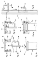
- the ventilation grid according to the invention shown in the figures comprises four types of major constituent elements, namely a frame formed by vertical uprights 1 and horizontal crosspieces 2, vertical stiffening profiles 3, several support elements 4 and several longitudinal blades 6.
- the grid further comprises fixing screws 5 and retaining rods 41 integral with the support elements 4.
- the uprights 1, the crosspieces 2, the stiffening profiles 3, the support elements 4 and the longitudinal blades 6 can be made from extruded or drawn metal profiles.
- the preferred metal is aluminum. However, some of these elements may be made other than by extrusion, for example by folding or molding.
- the vertical uprights 1 and the horizontal crosspieces 2 forming the frame of the grid are advantageously made from a metal section of identical shape, or more particularly of identical section.
- the uprights can be used in place of sleepers horizontal, and vice versa.
- the section of a vertical upright 1. This section is preferably identical and constant over the entire length of the amount. This is the case anyway when the uprights and sleepers are made from extruded or drawn profiles.
- the amount 1 of Figure 2 comprises two branches 11 and 12 which extend generally at right angles to one another.
- the branch 11, or outer leg is intended to extend on the wall or the wall adjacent (e) to the bay to be provided with the ventilation grid according to the invention.
- all the outer branches 11 extend in the extension of one another in a single plane located outside the bay to be closed.
- This external branch 11 can be provided with several profiles whose functions can be very diverse, such as strengthening, stiffening, support or fixation.
- the inner branch 12 is intended to extend into the bay on its periphery.
- the internal branches 12 of the crosspieces and uprights are also joined to form a closed frame.
- the branch 12 comprises different housings or recesses for fixing or holding some other parts of the grid, such as stiffening profiles, screws and blade support elements 4.
- the branch 12 comprises a groove 13 which extends here vertically on the height of the upright 1. This groove 13 comprises a bottom core 130 and two substantially parallel lateral flanges 131.
- the housing 13 is widely open on the inside of the bay and advantageously does not include any profile allowing the retention or the maintaining an element inside the housing 13. In other words, it is possible to directly access the interior of the groove 13 without having to introduce the element through one end of the groove.
- the inner leg 12 defines a holding or retaining recess 14 which is also open towards the inside of the bay, like the groove 13.
- the inner leg 12 is also provided with fixing means 15, which present here in the form of a screw housing.
- this screw housing is in the form of an open longitudinal channel which extends along the length of the upright. In other words, the opening of the longitudinal channel also extends towards the interior of the bay, as the recess 14 and the groove 13.
- the longitudinal channel 15 does not need to be internally threaded: it can however be provided with teeth or notches favoring the taking of screw threaded dowels fixing, as will be seen below.
- the longitudinal channel 15 is closest to the outer branch 11.
- the recess 12 is located behind the channel 15 relative to the outer branch 11, while the groove 13 is furthest from the outer branch 11.
- the vertical sections 3, with reference to FIG. 2, also comprise a bottom web 30 and two lateral flanges 31 which terminate in reentrant flaps 32. It thus defines an internal engagement rail 34 whose opening is narrowed. by the reentrant flaps 32.
- the profile 3 comprises two longitudinal screw housings 33 which are also in the form of longitudinal channels open along the length of the profile 3.
- the core 30 forms the bottom of the profile while the lateral flanges 31 form the longitudinal sections of the profile.
- the opening of the engagement rail is defined between the two reentrant flaps 32 and at each end of the profile.
- FIG. 4 shows an enlarged manner a blade support member 4 according to the invention.
- This part which can advantageously be made by extrusion of aluminum, has a constant section. Its width is of the order of a centimeter to a few centimeters. Its length is of the order of 10 to 40 centimeters.
- the support element 4 comprises a sole 43 from which extends a series of legs, branches or flanges 42, 44, 46 and 47.
- the sole 43 may be perfectly straight, but preferably it forms a very slight angle so as to define two parts of flanges 431 and 432.
- the sole portion 432 does not extend in the extension of the sole portion 431. It can be noted in particular the slight bending of the part 432 with respect to the dotted line which extends into the extension of the sole portion 431.
- the small boss 433 marks the location of the elbow formed between the parts 431 and 432. It will be seen below what is the function of the light bend and the boss 433.
- a first series of four tabs 46 extend substantially perpendicularly from the flange 43, upwards, with reference to FIG. 4. These lugs 46 end with a blade attachment profile 461 intended to receive a fixing lug. However, it can be seen that the tab 46 on the far left in FIG. 4 is furthermore provided with a detent flange 42 which advantageously forms a snap-fastening profile.
- the other three legs 46 are identical.
- the blade support member 4 also includes four legs 47 and 44 which each form a blade edge receiving housing 476. On the other hand, two of the branches 47 form a screw-through housing 45.
- the extreme right of FIG. 4 is referenced 44 and comprises a bending so that the end portion of the branch 44 extends to the right when looking at FIG. 4.
- the right end of the sole portion 435 is formed with a bearing 434 in which a retaining pin 41 is received.
- the retaining pin 41 is longer than the sole width, so that both ends of the shank protrude from the bearing 434. as can be seen for example in Figures 5a and 5e.
- another retaining pin 411 may be housed at the left end of the sole 43 at the level where the tab 46 extends from the sole.
- a bearing member may be formed at this location to receive the retainer pin 411.
- blade support member should not be considered as limiting or unique.
- This blade support member is made for attachment of four blades, but blade support members for one, two, three, five, six or seven or more blades can be well imagined. It is also possible to realize the blade support element without the bending of the sole 43. It is also possible to integrate the retaining pin 41 to the sole. We will see below what are the different functions of the different parts of the blade support element 4 of FIG. 4.
- the blades 6 are visible in Figures 3a, 3b and 3c.
- Each blade is in the form of a longitudinal profiled wing comprising a fixing edge 61, a free edge 62 and a fixing pin 63 which is located between the two edges 61 and 62.
- the fixing edge 61 is intended to be received and fixed inside the housings 476 formed by the branches 47 and 44.
- the fixing lugs 63 which are in the form of a longitudinal projecting rib, are intended to be received inside the profiles receiving members 461 formed by the tabs 46.
- the free edges 62 they extend substantially in the plane formed by the outer branches 11 of the frame.
- the blades 6 are thus held substantially parallel to each other at a distance from one another so as to form a perforated formation. This is clearly visible in Figure 3b.
- two vertical stiffening profiles 3 extend respectively adjacent to the two vertical uprights 1.
- an intermediate vertical stiffening section 3 can be provided between the two crosspieces 2. This intermediate profile is particularly necessary when the frame has a large width.
- a longitudinal slice of the profile 3 formed by the flange 31 is received inside the vertical groove 13 formed by the upright 1.
- the profile 3 is simply introduced frontally inside the groove 13 without having to introduce it through one end of the groove.
- the opening of the housing 34 then points forward or to the outer branch 11.
- the profile 3 is then not maintained or fixed inside the groove 13, and more generally on the upright 1.
- the free ends of the profile are engaged in the grooves 13 formed by the upper and lower rails, as can be seen in Figures 3a and 3c.
- the blade support members 4 are mounted in the engagement rails 34 formed by the profiles 3.
- the holding or fixing of the blade support members in the profile rails can be carried out by any technique : it is sufficient for the rail support elements to be
- the function of the stiffening profiles 3 is to ensure a solid and fixed support of the blade support elements 4 which are then provided with the blades 6.
- a technique for fixing the support elements. of blades in the profile rails It is of course possible to use another type of blade support element than that of FIG. 4 in the context of the present invention.
- the blade support elements are held inside the rails for engaging the profiles. As seen previously, the edge of the sections 3 is simply engaged inside the grooves 13 of the two uprights 1.
- some or all of the blade support elements 4 are attached to the upright 1.
- the fixing of these blade support elements is carried out directly, for example by means of screws 5 which pass through the screw housings 45 formed by the branches 47.
- These screws 5 comprise a head 41 resting on one end of the passage housing. 45 and a threaded rod 52 which passes through the passage housing and engages inside the open longitudinal channel 15 which serves as fixing means. This is clearly visible in FIG. 2.
- two screws are sufficient for an upright 1, as can be seen in FIG. 1. Screws 5 can be dispensed with in the case of small grids, the profiles 3 the blade support elements and the blades being kept in the frame by the friction between the different parts.
- screws 5 that secure the blade support members to the frame can be dispensed with. Indeed, it is sufficient that the stiffening profiles are engaged in the respective grooves to ensure the maintenance of the grid in the frame.
- the grid can be mounted progressively in a pre-mounted frame. Placing the blades on their support elements ensures the locking of the stiffening profiles in their respective grooves.
- the screws improve the stability and strength of the grid as a whole avoiding any annoying structure noise.
- FIGS. 3a, 3b and 3c as well as to FIGS. 5a to 5f to explain in which advantageous manner the blade support elements are held inside the rails 34 of the profiles 3.
- the fixing technique used to fix the blade support elements on the profiles can be implemented elsewhere than in the context of a ventilation grid. Indeed, this fastening technique can also be used for fixing the blades in the context of a facade cladding, in which there is no frame.
- Figure 3b it can be seen that the flanges 43 of the blade support members are fully received within the rails 34 of the profile.
- the width of the sole is advantageously less than the opening of the rail taken between the two reentrant flaps 34.
- the bearing 434 of the sole is provided with a retaining rod 41 whose length is greater than the width of the sole.
- the sole is not possible to engage frontally the sole equipped with its retaining pin 41 inside the rail.
- We can introduce the sole with its retaining pin 41 in the rail by one end of the rail. However, this is not always convenient. It is more advantageous to introduce the sole directly frontally inside the rail without passing through one end.
- the rod 41 is then already located behind the reentrant flaps 32.
- the projecting ends of the retaining rod 41 are then engaged behind the reentrant flaps 32.
- the retaining head is then trapped in the rail 34.
- the entire sole 43 is inserted inside the rail 34 of the profile 3. This is clearly visible in Figures 3a, 3b and 3c.
- a retaining pin 411 similar or identical to the rod 41 inside the rail at the location shown in Figure 4, that is to say say on the far left from the sole 43 to the level where the first leg 46 extends.
- this retaining rod 411 it is necessary to press the sole against the bottom core 30 of the profile 3. This involves deforming the sole 43 which is performed initially with a slight elbow, as we saw previously. The boss 433 comes into contact with the bottom core 30 and plays the role of pivot to allow the "unbundling" of the sole 43. The sole is then found in a substantially straight configuration. The dewaxing of the sole 43 eliminates any play that could produce undesirable structural noise. This plays on the elasticity of the sole to ensure a fixing without play of the sole inside the rail. It can thus be said that the blade support member comprises spring means or deformable means for eliminating the games.
- the free edge 62 of the lower frame blade completely covers the inner branch 12 and even a portion of the outer branch 11 of the bottom rail 2. This allows a drainage of runoff without the risk of water stagnating inside the frame.
- the invention we obtain a ventilation grille composed of simple elements to manufacture and very simple to assemble.
- the grid is perfectly free of play that could vibrate certain elements during the passage of air through the grid.
Landscapes
- Engineering & Computer Science (AREA)
- Chemical & Material Sciences (AREA)
- Combustion & Propulsion (AREA)
- Mechanical Engineering (AREA)
- General Engineering & Computer Science (AREA)
- Specific Sealing Or Ventilating Devices For Doors And Windows (AREA)
Applications Claiming Priority (1)
| Application Number | Priority Date | Filing Date | Title |
|---|---|---|---|
| FR0451502A FR2872889B1 (fr) | 2004-07-12 | 2004-07-12 | Grille de ventilation destinee a etre installee dans une baie |
Publications (2)
| Publication Number | Publication Date |
|---|---|
| EP1617155A1 true EP1617155A1 (de) | 2006-01-18 |
| EP1617155B1 EP1617155B1 (de) | 2007-11-28 |
Family
ID=34946071
Family Applications (1)
| Application Number | Title | Priority Date | Filing Date |
|---|---|---|---|
| EP20050106373 Not-in-force EP1617155B1 (de) | 2004-07-12 | 2005-07-12 | Lüftungsgitter |
Country Status (5)
| Country | Link |
|---|---|
| EP (1) | EP1617155B1 (de) |
| DE (1) | DE602005003512T2 (de) |
| ES (1) | ES2297621T3 (de) |
| FR (1) | FR2872889B1 (de) |
| PT (1) | PT1617155E (de) |
Cited By (2)
| Publication number | Priority date | Publication date | Assignee | Title |
|---|---|---|---|---|
| NL2002316C2 (nl) * | 2008-12-11 | 2010-06-16 | Vipco Systems N V | Inbraakwerend rooster. |
| FR3095501A1 (fr) * | 2019-04-26 | 2020-10-30 | Aldes Aeraulique | Installation de désenfumage |
Families Citing this family (1)
| Publication number | Priority date | Publication date | Assignee | Title |
|---|---|---|---|---|
| WO2008154001A1 (en) * | 2007-06-07 | 2008-12-18 | California Faucets Corporation | Aesthetic conduit end cap structure having concealed anchor attachments |
Citations (7)
| Publication number | Priority date | Publication date | Assignee | Title |
|---|---|---|---|---|
| US3968738A (en) | 1974-04-29 | 1976-07-13 | Champion International Corporation | Plastic louver frame assembly |
| GB2242735A (en) * | 1990-04-03 | 1991-10-09 | Tek Group Limited | Louvre ventilators |
| GB2300473A (en) | 1995-05-03 | 1996-11-06 | Lbj Profiles Limited | Louvre assembly |
| EP0770832A1 (de) | 1995-10-26 | 1997-05-02 | Autogyre La Société Anonyme dite : | Modulares Gitter |
| EP0913649A2 (de) * | 1997-10-29 | 1999-05-06 | van Houtte, Freddy | Lüftungsrost |
| EP1111313A1 (de) * | 1999-12-08 | 2001-06-27 | Autogyre | Befestigungsvorrichtung für Jalousieblätter |
| GB2373533A (en) * | 2001-03-20 | 2002-09-25 | Levolux At Ltd | Louvres and louvre systems |
-
2004
- 2004-07-12 FR FR0451502A patent/FR2872889B1/fr not_active Expired - Fee Related
-
2005
- 2005-07-12 DE DE200560003512 patent/DE602005003512T2/de active Active
- 2005-07-12 EP EP20050106373 patent/EP1617155B1/de not_active Not-in-force
- 2005-07-12 PT PT05106373T patent/PT1617155E/pt unknown
- 2005-07-12 ES ES05106373T patent/ES2297621T3/es active Active
Patent Citations (7)
| Publication number | Priority date | Publication date | Assignee | Title |
|---|---|---|---|---|
| US3968738A (en) | 1974-04-29 | 1976-07-13 | Champion International Corporation | Plastic louver frame assembly |
| GB2242735A (en) * | 1990-04-03 | 1991-10-09 | Tek Group Limited | Louvre ventilators |
| GB2300473A (en) | 1995-05-03 | 1996-11-06 | Lbj Profiles Limited | Louvre assembly |
| EP0770832A1 (de) | 1995-10-26 | 1997-05-02 | Autogyre La Société Anonyme dite : | Modulares Gitter |
| EP0913649A2 (de) * | 1997-10-29 | 1999-05-06 | van Houtte, Freddy | Lüftungsrost |
| EP1111313A1 (de) * | 1999-12-08 | 2001-06-27 | Autogyre | Befestigungsvorrichtung für Jalousieblätter |
| GB2373533A (en) * | 2001-03-20 | 2002-09-25 | Levolux At Ltd | Louvres and louvre systems |
Cited By (3)
| Publication number | Priority date | Publication date | Assignee | Title |
|---|---|---|---|---|
| NL2002316C2 (nl) * | 2008-12-11 | 2010-06-16 | Vipco Systems N V | Inbraakwerend rooster. |
| FR3095501A1 (fr) * | 2019-04-26 | 2020-10-30 | Aldes Aeraulique | Installation de désenfumage |
| EP3745039A1 (de) * | 2019-04-26 | 2020-12-02 | Aldes Aeraulique | Rauchabzugsanlage |
Also Published As
| Publication number | Publication date |
|---|---|
| DE602005003512D1 (de) | 2008-01-10 |
| FR2872889B1 (fr) | 2006-10-27 |
| EP1617155B1 (de) | 2007-11-28 |
| DE602005003512T2 (de) | 2008-10-23 |
| ES2297621T3 (es) | 2008-05-01 |
| FR2872889A1 (fr) | 2006-01-13 |
| PT1617155E (pt) | 2008-03-07 |
Similar Documents
| Publication | Publication Date | Title |
|---|---|---|
| EP0657672B1 (de) | Vorrichtung für die Stossverbindung von perforierten Abschnitten eines Kabelkanals | |
| EP3492675B1 (de) | Vorrichtung zum befestigen von lamellen an einem starren gitterpaneel, lamellenbefestigungskit an einem starren gitterpaneel und sichtschutzzaun, der mit diesem kit ausgestattet ist | |
| FR2697274A1 (fr) | Revêtement de mur avec système de support. | |
| EP1617155B1 (de) | Lüftungsgitter | |
| FR2630145A1 (fr) | Systeme de cloison demontable ou amovible a double paroi, et procede pour former une telle cloison | |
| EP0770832B1 (de) | Modulares Gitter | |
| EP1722111B1 (de) | Befestigungselement zur Befestigung eines Metallprofils auf einem Träger | |
| CA2973677A1 (fr) | Dispositif de fixation de panneau solaire | |
| FR3090807A1 (fr) | Systeme de connexion et pergola comprenant ledit systeme de connexion | |
| FR2800437A1 (fr) | Ensemble constitue d'un support rigide et d'un habillage du support, profile d'habillage et son utilisation pour un tel ensemble | |
| FR2930315A1 (fr) | Dispositif pour le raccordement de deux elements profiles selon un angle quelconque. | |
| EP3351811A1 (de) | Montagekit für halterungsstrukturen, montageverfahren und halterungsstrukturen, die mithilfe dieses montagekits zusammengebaut wurden | |
| EP0762586A1 (de) | Gehäuse für elektrische Geräte | |
| WO2012120223A1 (fr) | Profile universel | |
| FR2998608A1 (fr) | Volets roulants | |
| FR2854184A1 (fr) | Systeme de fixation de lames et parement de facade comprenant un tel systeme | |
| WO2004044340A1 (fr) | Faux-plafond mixte a toile tendue | |
| FR2522044A1 (fr) | Profile pour la realisation de cloisons amovibles et systeme de cloison utilisant ce profile | |
| EP2273636B1 (de) | Verlängerungszubehörteil eines Teilstücks einer Ablaufrinne | |
| FR2836510A1 (fr) | Grille | |
| EP3346072B1 (de) | Markisenstruktur | |
| FR2642789A1 (fr) | Coffrage de volet roulant pour installation sur la partie superieure d'un cadre de dormant | |
| EP1655426B1 (de) | Schalungssatz, insbesondere für den Bau von Schwimmbädern, und entsprechende Endstücke | |
| FR3024487A1 (fr) | Structure de menuiserie comprenant un dormant et un coffre de volet roulant | |
| FR2854194A1 (fr) | Dispositif pour le coffrage de volet roulant, notamment pour construction legere, telle que veranda |
Legal Events
| Date | Code | Title | Description |
|---|---|---|---|
| PUAI | Public reference made under article 153(3) epc to a published international application that has entered the european phase |
Free format text: ORIGINAL CODE: 0009012 |
|
| AK | Designated contracting states |
Kind code of ref document: A1 Designated state(s): AT BE BG CH CY CZ DE DK EE ES FI FR GB GR HU IE IS IT LI LT LU LV MC NL PL PT RO SE SI SK TR |
|
| AX | Request for extension of the european patent |
Extension state: AL BA HR MK YU |
|
| AKX | Designation fees paid | ||
| REG | Reference to a national code |
Ref country code: DE Ref legal event code: 8566 |
|
| 17P | Request for examination filed |
Effective date: 20061004 |
|
| RBV | Designated contracting states (corrected) |
Designated state(s): AT BE BG CH CY CZ DE DK EE ES FI FR GB GR HU IE IS IT LI LT LU LV MC NL PL PT RO SE SI SK TR |
|
| GRAP | Despatch of communication of intention to grant a patent |
Free format text: ORIGINAL CODE: EPIDOSNIGR1 |
|
| RIN1 | Information on inventor provided before grant (corrected) |
Inventor name: GAMAIN, CLAUDE |
|
| GRAS | Grant fee paid |
Free format text: ORIGINAL CODE: EPIDOSNIGR3 |
|
| GRAA | (expected) grant |
Free format text: ORIGINAL CODE: 0009210 |
|
| AK | Designated contracting states |
Kind code of ref document: B1 Designated state(s): AT BE BG CH CY CZ DE DK EE ES FI FR GB GR HU IE IS IT LI LT LU LV MC NL PL PT RO SE SI SK TR |
|
| REG | Reference to a national code |
Ref country code: GB Ref legal event code: FG4D Free format text: NOT ENGLISH |
|
| REG | Reference to a national code |
Ref country code: IE Ref legal event code: FG4D Free format text: LANGUAGE OF EP DOCUMENT: FRENCH |
|
| REG | Reference to a national code |
Ref country code: CH Ref legal event code: EP |
|
| REF | Corresponds to: |
Ref document number: 602005003512 Country of ref document: DE Date of ref document: 20080110 Kind code of ref document: P |
|
| REG | Reference to a national code |
Ref country code: PT Ref legal event code: SC4A Free format text: AVAILABILITY OF NATIONAL TRANSLATION Effective date: 20080226 |
|
| GBT | Gb: translation of ep patent filed (gb section 77(6)(a)/1977) |
Effective date: 20080305 |
|
| REG | Reference to a national code |
Ref country code: CH Ref legal event code: NV Representative=s name: BOVARD AG PATENTANWAELTE |
|
| PG25 | Lapsed in a contracting state [announced via postgrant information from national office to epo] |
Ref country code: SE Free format text: LAPSE BECAUSE OF FAILURE TO SUBMIT A TRANSLATION OF THE DESCRIPTION OR TO PAY THE FEE WITHIN THE PRESCRIBED TIME-LIMIT Effective date: 20080228 |
|
| REG | Reference to a national code |
Ref country code: ES Ref legal event code: FG2A Ref document number: 2297621 Country of ref document: ES Kind code of ref document: T3 |
|
| PG25 | Lapsed in a contracting state [announced via postgrant information from national office to epo] |
Ref country code: SI Free format text: LAPSE BECAUSE OF FAILURE TO SUBMIT A TRANSLATION OF THE DESCRIPTION OR TO PAY THE FEE WITHIN THE PRESCRIBED TIME-LIMIT Effective date: 20071128 Ref country code: PL Free format text: LAPSE BECAUSE OF FAILURE TO SUBMIT A TRANSLATION OF THE DESCRIPTION OR TO PAY THE FEE WITHIN THE PRESCRIBED TIME-LIMIT Effective date: 20071128 Ref country code: LV Free format text: LAPSE BECAUSE OF FAILURE TO SUBMIT A TRANSLATION OF THE DESCRIPTION OR TO PAY THE FEE WITHIN THE PRESCRIBED TIME-LIMIT Effective date: 20071128 Ref country code: LT Free format text: LAPSE BECAUSE OF FAILURE TO SUBMIT A TRANSLATION OF THE DESCRIPTION OR TO PAY THE FEE WITHIN THE PRESCRIBED TIME-LIMIT Effective date: 20071128 Ref country code: IS Free format text: LAPSE BECAUSE OF FAILURE TO SUBMIT A TRANSLATION OF THE DESCRIPTION OR TO PAY THE FEE WITHIN THE PRESCRIBED TIME-LIMIT Effective date: 20080328 Ref country code: FI Free format text: LAPSE BECAUSE OF FAILURE TO SUBMIT A TRANSLATION OF THE DESCRIPTION OR TO PAY THE FEE WITHIN THE PRESCRIBED TIME-LIMIT Effective date: 20071128 Ref country code: BG Free format text: LAPSE BECAUSE OF FAILURE TO SUBMIT A TRANSLATION OF THE DESCRIPTION OR TO PAY THE FEE WITHIN THE PRESCRIBED TIME-LIMIT Effective date: 20080228 |
|
| PG25 | Lapsed in a contracting state [announced via postgrant information from national office to epo] |
Ref country code: AT Free format text: LAPSE BECAUSE OF FAILURE TO SUBMIT A TRANSLATION OF THE DESCRIPTION OR TO PAY THE FEE WITHIN THE PRESCRIBED TIME-LIMIT Effective date: 20071128 |
|
| PG25 | Lapsed in a contracting state [announced via postgrant information from national office to epo] |
Ref country code: DK Free format text: LAPSE BECAUSE OF FAILURE TO SUBMIT A TRANSLATION OF THE DESCRIPTION OR TO PAY THE FEE WITHIN THE PRESCRIBED TIME-LIMIT Effective date: 20071128 Ref country code: CZ Free format text: LAPSE BECAUSE OF FAILURE TO SUBMIT A TRANSLATION OF THE DESCRIPTION OR TO PAY THE FEE WITHIN THE PRESCRIBED TIME-LIMIT Effective date: 20071128 |
|
| PG25 | Lapsed in a contracting state [announced via postgrant information from national office to epo] |
Ref country code: RO Free format text: LAPSE BECAUSE OF FAILURE TO SUBMIT A TRANSLATION OF THE DESCRIPTION OR TO PAY THE FEE WITHIN THE PRESCRIBED TIME-LIMIT Effective date: 20071128 Ref country code: SK Free format text: LAPSE BECAUSE OF FAILURE TO SUBMIT A TRANSLATION OF THE DESCRIPTION OR TO PAY THE FEE WITHIN THE PRESCRIBED TIME-LIMIT Effective date: 20071128 |
|
| PLBE | No opposition filed within time limit |
Free format text: ORIGINAL CODE: 0009261 |
|
| STAA | Information on the status of an ep patent application or granted ep patent |
Free format text: STATUS: NO OPPOSITION FILED WITHIN TIME LIMIT |
|
| 26N | No opposition filed |
Effective date: 20080829 |
|
| PG25 | Lapsed in a contracting state [announced via postgrant information from national office to epo] |
Ref country code: GR Free format text: LAPSE BECAUSE OF FAILURE TO SUBMIT A TRANSLATION OF THE DESCRIPTION OR TO PAY THE FEE WITHIN THE PRESCRIBED TIME-LIMIT Effective date: 20080229 |
|
| PG25 | Lapsed in a contracting state [announced via postgrant information from national office to epo] |
Ref country code: EE Free format text: LAPSE BECAUSE OF FAILURE TO SUBMIT A TRANSLATION OF THE DESCRIPTION OR TO PAY THE FEE WITHIN THE PRESCRIBED TIME-LIMIT Effective date: 20071128 |
|
| PG25 | Lapsed in a contracting state [announced via postgrant information from national office to epo] |
Ref country code: CY Free format text: LAPSE BECAUSE OF FAILURE TO SUBMIT A TRANSLATION OF THE DESCRIPTION OR TO PAY THE FEE WITHIN THE PRESCRIBED TIME-LIMIT Effective date: 20071128 |
|
| PG25 | Lapsed in a contracting state [announced via postgrant information from national office to epo] |
Ref country code: HU Free format text: LAPSE BECAUSE OF FAILURE TO SUBMIT A TRANSLATION OF THE DESCRIPTION OR TO PAY THE FEE WITHIN THE PRESCRIBED TIME-LIMIT Effective date: 20080529 |
|
| PGFP | Annual fee paid to national office [announced via postgrant information from national office to epo] |
Ref country code: LU Payment date: 20100625 Year of fee payment: 6 Ref country code: MC Payment date: 20100618 Year of fee payment: 6 Ref country code: PT Payment date: 20100617 Year of fee payment: 6 |
|
| PG25 | Lapsed in a contracting state [announced via postgrant information from national office to epo] |
Ref country code: TR Free format text: LAPSE BECAUSE OF FAILURE TO SUBMIT A TRANSLATION OF THE DESCRIPTION OR TO PAY THE FEE WITHIN THE PRESCRIBED TIME-LIMIT Effective date: 20071128 |
|
| PGFP | Annual fee paid to national office [announced via postgrant information from national office to epo] |
Ref country code: CH Payment date: 20100708 Year of fee payment: 6 Ref country code: ES Payment date: 20100727 Year of fee payment: 6 Ref country code: IE Payment date: 20100701 Year of fee payment: 6 Ref country code: NL Payment date: 20100621 Year of fee payment: 6 |
|
| PGFP | Annual fee paid to national office [announced via postgrant information from national office to epo] |
Ref country code: DE Payment date: 20100705 Year of fee payment: 6 Ref country code: GB Payment date: 20100621 Year of fee payment: 6 Ref country code: IT Payment date: 20100724 Year of fee payment: 6 |
|
| PGFP | Annual fee paid to national office [announced via postgrant information from national office to epo] |
Ref country code: BE Payment date: 20100803 Year of fee payment: 6 |
|
| REG | Reference to a national code |
Ref country code: CH Ref legal event code: PFA Owner name: AUTOGYRE Free format text: AUTOGYRE#31, RUE DE LA JUSTICE#77000 VAUX LE PENIL (FR) $ ALUGRIP#31, RUE DE VERSAILLES#92410 VILLE D'AVRAY (FR) -TRANSFER TO- AUTOGYRE#31, RUE DE LA JUSTICE#77000 VAUX LE PENIL (FR) $ ALUGRIP#31, RUE DE VERSAILLES#92410 VILLE D'AVRAY (FR) |
|
| REG | Reference to a national code |
Ref country code: PT Ref legal event code: MM4A Free format text: LAPSE DUE TO NON-PAYMENT OF FEES Effective date: 20120112 |
|
| BERE | Be: lapsed |
Owner name: ALUGRIP Effective date: 20110731 Owner name: AUTOGYRE Effective date: 20110731 |
|
| REG | Reference to a national code |
Ref country code: NL Ref legal event code: V1 Effective date: 20120201 |
|
| PG25 | Lapsed in a contracting state [announced via postgrant information from national office to epo] |
Ref country code: MC Free format text: LAPSE BECAUSE OF NON-PAYMENT OF DUE FEES Effective date: 20110731 |
|
| REG | Reference to a national code |
Ref country code: CH Ref legal event code: PL |
|
| GBPC | Gb: european patent ceased through non-payment of renewal fee |
Effective date: 20110712 |
|
| REG | Reference to a national code |
Ref country code: IE Ref legal event code: MM4A |
|
| PG25 | Lapsed in a contracting state [announced via postgrant information from national office to epo] |
Ref country code: BE Free format text: LAPSE BECAUSE OF NON-PAYMENT OF DUE FEES Effective date: 20110731 Ref country code: DE Free format text: LAPSE BECAUSE OF NON-PAYMENT OF DUE FEES Effective date: 20120201 Ref country code: CH Free format text: LAPSE BECAUSE OF NON-PAYMENT OF DUE FEES Effective date: 20110731 Ref country code: LI Free format text: LAPSE BECAUSE OF NON-PAYMENT OF DUE FEES Effective date: 20110731 |
|
| REG | Reference to a national code |
Ref country code: DE Ref legal event code: R119 Ref document number: 602005003512 Country of ref document: DE Effective date: 20120201 |
|
| PG25 | Lapsed in a contracting state [announced via postgrant information from national office to epo] |
Ref country code: NL Free format text: LAPSE BECAUSE OF NON-PAYMENT OF DUE FEES Effective date: 20120201 Ref country code: IT Free format text: LAPSE BECAUSE OF NON-PAYMENT OF DUE FEES Effective date: 20110712 Ref country code: PT Free format text: LAPSE BECAUSE OF NON-PAYMENT OF DUE FEES Effective date: 20120112 |
|
| PG25 | Lapsed in a contracting state [announced via postgrant information from national office to epo] |
Ref country code: GB Free format text: LAPSE BECAUSE OF NON-PAYMENT OF DUE FEES Effective date: 20110712 |
|
| PG25 | Lapsed in a contracting state [announced via postgrant information from national office to epo] |
Ref country code: IE Free format text: LAPSE BECAUSE OF NON-PAYMENT OF DUE FEES Effective date: 20110712 |
|
| REG | Reference to a national code |
Ref country code: ES Ref legal event code: FD2A Effective date: 20121122 |
|
| PG25 | Lapsed in a contracting state [announced via postgrant information from national office to epo] |
Ref country code: ES Free format text: LAPSE BECAUSE OF NON-PAYMENT OF DUE FEES Effective date: 20110713 |
|
| PG25 | Lapsed in a contracting state [announced via postgrant information from national office to epo] |
Ref country code: LU Free format text: LAPSE BECAUSE OF NON-PAYMENT OF DUE FEES Effective date: 20110712 |
|
| PGFP | Annual fee paid to national office [announced via postgrant information from national office to epo] |
Ref country code: FR Payment date: 20140728 Year of fee payment: 10 |
|
| REG | Reference to a national code |
Ref country code: FR Ref legal event code: ST Effective date: 20160331 |
|
| PG25 | Lapsed in a contracting state [announced via postgrant information from national office to epo] |
Ref country code: FR Free format text: LAPSE BECAUSE OF NON-PAYMENT OF DUE FEES Effective date: 20150731 |