EP1616632A2 - Pump to spray a product in different positions and container therefor - Google Patents
Pump to spray a product in different positions and container therefor Download PDFInfo
- Publication number
- EP1616632A2 EP1616632A2 EP05023001A EP05023001A EP1616632A2 EP 1616632 A2 EP1616632 A2 EP 1616632A2 EP 05023001 A EP05023001 A EP 05023001A EP 05023001 A EP05023001 A EP 05023001A EP 1616632 A2 EP1616632 A2 EP 1616632A2
- Authority
- EP
- European Patent Office
- Prior art keywords
- pump
- pumping chamber
- pump body
- product
- container
- Prior art date
- Legal status (The legal status is an assumption and is not a legal conclusion. Google has not performed a legal analysis and makes no representation as to the accuracy of the status listed.)
- Granted
Links
Images

Classifications
-
- B—PERFORMING OPERATIONS; TRANSPORTING
- B05—SPRAYING OR ATOMISING IN GENERAL; APPLYING FLUENT MATERIALS TO SURFACES, IN GENERAL
- B05B—SPRAYING APPARATUS; ATOMISING APPARATUS; NOZZLES
- B05B11/00—Single-unit hand-held apparatus in which flow of contents is produced by the muscular force of the operator at the moment of use
- B05B11/0005—Components or details
- B05B11/0059—Components or details allowing operation in any orientation, e.g. for discharge in inverted position
-
- B—PERFORMING OPERATIONS; TRANSPORTING
- B05—SPRAYING OR ATOMISING IN GENERAL; APPLYING FLUENT MATERIALS TO SURFACES, IN GENERAL
- B05B—SPRAYING APPARATUS; ATOMISING APPARATUS; NOZZLES
- B05B11/00—Single-unit hand-held apparatus in which flow of contents is produced by the muscular force of the operator at the moment of use
- B05B11/0005—Components or details
- B05B11/0037—Containers
- B05B11/0039—Containers associated with means for compensating the pressure difference between the ambient pressure and the pressure inside the container, e.g. pressure relief means
- B05B11/0044—Containers associated with means for compensating the pressure difference between the ambient pressure and the pressure inside the container, e.g. pressure relief means compensating underpressure by ingress of atmospheric air into the container, i.e. with venting means
- B05B11/00442—Containers associated with means for compensating the pressure difference between the ambient pressure and the pressure inside the container, e.g. pressure relief means compensating underpressure by ingress of atmospheric air into the container, i.e. with venting means the means being actuated by the difference between the atmospheric pressure and the pressure inside the container
-
- B—PERFORMING OPERATIONS; TRANSPORTING
- B05—SPRAYING OR ATOMISING IN GENERAL; APPLYING FLUENT MATERIALS TO SURFACES, IN GENERAL
- B05B—SPRAYING APPARATUS; ATOMISING APPARATUS; NOZZLES
- B05B11/00—Single-unit hand-held apparatus in which flow of contents is produced by the muscular force of the operator at the moment of use
- B05B11/01—Single-unit hand-held apparatus in which flow of contents is produced by the muscular force of the operator at the moment of use characterised by the means producing the flow
- B05B11/10—Pump arrangements for transferring the contents from the container to a pump chamber by a sucking effect and forcing the contents out through the dispensing nozzle
- B05B11/1001—Piston pumps
- B05B11/1016—Piston pumps the outlet valve having a valve seat located downstream a movable valve element controlled by a pressure actuated controlling element
-
- B—PERFORMING OPERATIONS; TRANSPORTING
- B05—SPRAYING OR ATOMISING IN GENERAL; APPLYING FLUENT MATERIALS TO SURFACES, IN GENERAL
- B05B—SPRAYING APPARATUS; ATOMISING APPARATUS; NOZZLES
- B05B11/00—Single-unit hand-held apparatus in which flow of contents is produced by the muscular force of the operator at the moment of use
- B05B11/0005—Components or details
- B05B11/0037—Containers
- B05B11/0039—Containers associated with means for compensating the pressure difference between the ambient pressure and the pressure inside the container, e.g. pressure relief means
- B05B11/0044—Containers associated with means for compensating the pressure difference between the ambient pressure and the pressure inside the container, e.g. pressure relief means compensating underpressure by ingress of atmospheric air into the container, i.e. with venting means
Definitions
- the present invention relates to a pump to be mounted on a container and for dispensing a product in different positions, including head up or head down.
- the patent application FR 2,528,122 discloses a pump for dispensing a product head up or upside down, comprising a pump body and a movable assembly in the pump body, defining therewith a pumping chamber. variable volume.
- the pump body has an opening allowing the product contained in the container to enter the pumping chamber when the pump is used upside down.
- the movable assembly comprises a lip for isolating the aforementioned opening of the pumping chamber after a certain depression in the pump body. If the pump is held upside down for a long period, a risk of product leakage through this opening is not excluded, especially if the product is low viscosity.
- No. 5,622,286 discloses a pump with an orifice in the pump body, this orifice allowing only a return of air and not the supply of the pumping chamber when the pump is upside down.
- the invention aims in particular to provide a pump which has a relatively simple structure while allowing to distribute satisfactorily a product, even low viscosity, head up or upside down.
- the invention can make it possible to produce the pump with an air intake passage which can extend at least partially in the pump body, for example by means of a clearance formed between a rod of the moving assembly and the fixed part. . This can avoid having to implement complex and expensive sealing means to achieve between the aforementioned rod and the fixed part.
- the invention also allows in the case where the air intake is performed through a clearance between the rod and the fixed part to reduce the risk of product leakage in case of maintenance upside down the pump, whether at rest or when the moving assembly is in an end position in the pump body, since the second lip can prevent the product entering through the opening to gain from the inside of the pump body the recovery passage of air and flow out of the pump.
- the pump comprises an annular seal intended to be inserted between the fixed part and the upper end of the neck of the container on which the pump is mounted, this seal comprising a radially inner portion which on the one hand can apply to the pump body to prevent the product contained in the container from flowing outwards and secondly can deviate from it under the effect of a depression in the container to allow the air intake.
- the seal does not apply to the pump body. However, the clearance between the seal and the pump body is then low enough to prevent the passage of the product, while allowing the passage of air.
- the pump comprises a base portion for fixing the pump on the container, the pump body being fixed, in particular by snapping, on this base portion.
- the aforementioned air intake passage may be formed at least partially between this base portion and the pump body.
- At least one of the first and second lips is arranged to permanently apply to the pump body, and preferably the two lips are permanently applied to the body pump.
- the first lip may have a substantially frustoconical shape diverging towards the pumping chamber and the second lip concave arcuate shape towards the inner surface of the pump body, applying at the lower and upper edges to the pump body.
- the mobile assembly may comprise a shutter arranged to close an outlet passage of the product when the volume of the pumping chamber increases and to release this passage when the volume of the chamber of pumping decreases and the pressure of the product in the pumping chamber reaches a predefined value.
- the pump comprises other pre-compression mechanisms or is not pre-compression.
- the movable assembly may comprise an interior space into which the outlet passage of the product opens and in which the shutter is disposed.
- This shutter may comprise a tubular body closed at its upper end by a substantially frustoconical portion, adapted to close off the outlet passage of the product.
- the shutter may further comprise an annular lip, outside the tubular body, adapted to be applied on a wall delimiting the aforementioned internal space, this annular lip, when the pump is observed head up, having a substantially frustoconical shape diverging upward and located below the passage or passages communicating said interior space and the pumping chamber.
- the shutter can be returned to its closed position by a resilient return element disposed in the interior space, this elastic return element being for example a helical spring working in compression.
- the pump comprises an elastic return element adapted to recall the moving assembly in its rest position.
- This elastic return element can be arranged in the pumping chamber and comprise a helical spring working in compression.
- This return element could also, without departing from the scope of the present invention, be disposed outside the pumping chamber, especially if it is desired to avoid contact with the product.
- the pump body is arranged to allow the attachment of a dip tube.
- the pump comprising a suction valve closing when the volume of the pumping chamber decreases and opens when the volume of the pumping chamber increases, the valve can be arranged to allow the supply of the pumping chamber produced by means of the dip tube when the pump is used upside down.
- the invention also relates to a container equipped with a pump as defined above.
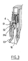
- the pump 1 shown in Figures 1 and 2 is intended to be mounted on a neck 52 of a container 53, apparent in Figure 3, containing a product P to be dispensed, for example a low viscosity product such as a perfume .
- This pump 1 comprises a fixed part 2 and a mobile assembly 3 that can move along an axis X with respect to the fixed part 2.
- the latter comprises a base portion 4 comprising a mounting skirt 5, threaded internally, intended to be secured to the neck 52 of the container 53 by screwing in the example.
- the base portion 4 could be otherwise attached to the container neck without departing from the scope of the present invention by snapping, gluing, welding or crimping for example.
- the fixed part 2 further comprises a pump body 16 defining with the moving assembly 3 a pumping chamber 17, of variable volume.
- the moving assembly 3 comprises a piston 30 made in one piece with a hollow rod 31 at the upper end of which is fixed a push-button 25.
- the mounting skirt 5 is extended upwards by a neck 7, surrounding a central portion 8 of the base portion 4.
- This central portion 8 comprises two tubular walls 9 and 12, coaxial, interconnected by an annular wall 11 to their upper end, and defines an annular groove open downwards, in which is engaged the pump body 16.
- the central portion 8 is connected at its lower end to the neck 7 by an annular wall 10 extending perpendicularly to the axis X.
- This passage 13 defines at its lower end a frustoconical surface 13a of axis X, diverging downwards, against which can sealingly supporting a corresponding frustoconical surface 31a of the rod 31, converging upwards, when the pump is at rest, as illustrated in FIG.
- the radially outermost tubular wall 9 has, on its radially inner side, a bead 14 for snap-fastening the pump body 16 to the base part 4, the pump body 16 having for this purpose at its end upper annular bead 23.
- the base portion 4 carries an annular seal 51 intended to be interposed between the annular wall 10 and the upper end of the neck 52 of the container 53, as illustrated in FIG.
- the radially inner portion 51a of the seal 51 normally engages against the pump body 16 to prevent the product contained in the container from flowing outwardly.
- the pump body 16 has in the example considered a cylindrical portion 16a of revolution about the axis X and has at its lower end a tip 18 for fixing a dip tube 19.
- the nozzle 18 defines the seat of a ball suction valve 20.
- the latter is retained in its housing by at least one lug 21 of the pump body 16.
- the pump body 16 has an opening 24, located in the example considered substantially halfway up the latter, and making it possible to put the pumping chamber 17 in communication with the inside. of the container when the mobile assembly 3 is at rest, the volume of the pumping chamber then being maximum.
- the push-button 25 has a dispensing orifice 26 made with a conventional vortex channel nozzle 27, attached to the rest of the push button, which allows the dispensing of the product P in the form of a spray.
- the rod 31 comprises a channel 29 allowing the product to gain this orifice 26.
- the piston 30 comprises first 40 and second 41 annular lips.
- the first lip 40 is of substantially frustoconical shape, diverging towards the bottom of the pumping chamber 14 and bears sealingly on the inner surface of the cylindrical portion 16a of the pump body 16. This first lip 40 is located above the opening 24 when the pump is in its rest position, as shown in Figure 1.
- the second annular lip 41 is located above the first 40, and also applies sealingly to the inner surface of the cylindrical portion 16a of the pump body 16.
- This second lip 41 has in the example considered a form arcuate, concave towards the inner surface of the body 16, and is applied by lower edges 41a and upper 42b to the body 16.
- the rod 31 is extended inferiorly by an end piece 32, hollow, closed at its lower end.
- This end piece 32 is for example fixed by snapping on the rod 31, and has an outer shoulder 33 on which bears at its upper end a helical spring 34 working in compression, which rests at its lower end on the bottom of the pump body 16.
- Passages 36 are made between the pumping chamber 17, outside the end piece 32, and the interior space 35 thereof, to allow the product contained in the pumping chamber 17 to gain the channel. 29 when the volume of the pumping chamber 17 decreases.
- the moving assembly 3 comprises, in the interior space 35, a shutter 42 movable between a closed position closing the channel 29 and a dispensing position allowing the product to flow in the channel 29 to the orifice 26.
- the shutter 42 comprises a tubular body 43, of axis X, closed at its upper end by a frustoconical portion 44 adapted to be applied against a seat formed in the rod 31, to close the channel 29 when the pump is at rest , as illustrated in Figure 1.
- the shutter 42 further comprises an annular lip 46 outside the tubular body 43, adapted to be applied on the inner surface of the end piece 32.
- This annular lip 46 has, when the pump is seen upside down, a frustoconical shape diverging upwards, and is positioned below the passages 36 communicating the interior space 35 with the pumping chamber 17.
- a helical spring 45 working in compression recalls the shutter 42 in its closed position at rest, as can be seen in FIG. 1.
- This spring 45 bears at its lower end against the bottom of the end piece 32 and at its upper end against the base of the lip 46.
- the air can be sucked into it by circulating between the neck 7 and the push button 25 and when the latter is depressed, in the clearance existing between the rod 31 and the tubular wall 12, between the latter and the pump body 16, between the annular wall 11 and the body 16, then between the tubular wall 9 and the pump body 16 and finally between the gasket 51 and the body 16.
- FIG. 2 shows the air intake path 50.
- the air can circulate through diametrically opposed axial grooves formed in the bead 14.
- the radially inner portion 51a of the annular seal 51 can move slightly away from the pump body 16 , to allow the air flowing between the tubular wall 9 and the pump body 16 to gain inside the container, as can be seen in Figure 3.
- the operation of the pump 1 is as follows.
- the user presses down on the push-button 25, and the moving assembly 3 moves relative to the pump body 16, so that the pressure of the product contained in the pumping chamber 17 increases, the ball 20 being pressed against its seat.
- the shutter 42 remains in its closed position of the channel 29 until the pressure of the product in the interior space 35 above the annular lip 46 is sufficient to overcome the return force of the spring 45.
- the first lip 40 isolates the pumping chamber 17 from the opening 24 and the second annular lip 41 isolates the opening 24 of the air intake passage.
- the air intake can be performed along the path 50, to compensate inside the container the volume of product taken by the pump 1.
- the pumping chamber 17 can fill through the opening 24 through the fact that the air can be evacuated by the plunger tube.
- the distribution of the product is carried out in the same way as in head up position.
- the pump body may notably comprise not one, but several openings 24.
Landscapes
- Reciprocating Pumps (AREA)
- Closures For Containers (AREA)
- Containers And Packaging Bodies Having A Special Means To Remove Contents (AREA)
Abstract
La présente invention concerne une pompe (1) destinée à être fixée sur un récipient, comportant : - une partie fixe comprenant un corps de pompe (16), - un ensemble mobile (3) par rapport au corps de pompe (16) et définissant avec celui-ci une chambre de pompage de volume variable (17), - au moins une ouverture (24) dans le corps de pompe permettant à la chambre de pompage de communiquer avec l'intérieur du récipient et disposée de manière à permettre un fonctionnement tête en bas de la pompe, - un passage de reprise d'air entre la partie fixe (2) et l'ensemble mobile (3), ce passage étant distinct de ladite ouverture (24), - une première lèvre (40) agencée pour s'appliquer de manière étanche sur le corps de pompe (16) et empêcher une communication par ladite ouverture (24) entre l'intérieur du récipient et la chambre de pompage (17), et - une deuxième lèvre (41) agencée pour, au moins lorsque l'ensemble mobile est dans une position de fin de course et empêcher une communication à travers l'intérieur du corps de pompe et par ladite ouverture entre l'intérieur du récipient et l'extérieur.The present invention relates to a pump (1) intended to be fixed on a container, comprising: a fixed part comprising a pump body (16), a moving assembly (3) with respect to the pump body (16) and defining therewith a pumping chamber of variable volume (17), at least one opening (24) in the pump body allowing the pumping chamber to communicate with the interior of the container and arranged so as to allow upside down operation of the pump, - a return air passage between the fixed part (2) and the movable assembly (3), this passage being distinct from said opening (24), a first lip (40) arranged to seal on the pump body (16) and prevent communication by said opening (24) between the interior of the container and the pumping chamber (17), and a second lip (41) arranged for, at least when the moving assembly is in an end-of-travel position and preventing communication through the inside of the pump body and by said opening between the inside of the container and the 'outside.
Description
La présente invention a pour objet une pompe destinée à être montée sur un récipient et permettant de distribuer un produit dans différentes positions, notamment tête en haut ou tête en bas.The present invention relates to a pump to be mounted on a container and for dispensing a product in different positions, including head up or head down.
On connaît par la demande de brevet FR 2 528 122 une pompe permettant de distribuer un produit tête en haut ou tête en bas, comportant un corps de pompe et un ensemble mobile dans le corps de pompe, définissant avec celui-ci une chambre de pompage de volume variable. Le corps de pompe comporte une ouverture permettant au produit contenu dans le récipient de pénétrer dans la chambre de pompage lorsque la pompe est utilisée tête en bas. L'ensemble mobile comporte une lèvre permettant d'isoler l'ouverture précitée de la chambre de pompage après un certain enfoncement dans le corps de pompe. Si la pompe est maintenue tête en bas sur une longue période, un risque de fuite de produit par cette ouverture n'est pas exclu, notamment si le produit est peu visqueux.The patent application FR 2,528,122 discloses a pump for dispensing a product head up or upside down, comprising a pump body and a movable assembly in the pump body, defining therewith a pumping chamber. variable volume. The pump body has an opening allowing the product contained in the container to enter the pumping chamber when the pump is used upside down. The movable assembly comprises a lip for isolating the aforementioned opening of the pumping chamber after a certain depression in the pump body. If the pump is held upside down for a long period, a risk of product leakage through this opening is not excluded, especially if the product is low viscosity.
On connaît par le brevet US 5 622 286 une pompe avec un orifice dans le corps de pompe, cet orifice permettant uniquement une reprise d'air et non l'alimentation de la chambre de pompage lorsque la pompe est tête en bas.No. 5,622,286 discloses a pump with an orifice in the pump body, this orifice allowing only a return of air and not the supply of the pumping chamber when the pump is upside down.
L'invention vise notamment à proposer une pompe qui ait une structure relativement simple tout en permettant de distribuer de manière satisfaisante un produit, même peu visqueux, tête en haut ou tête en bas.The invention aims in particular to provide a pump which has a relatively simple structure while allowing to distribute satisfactorily a product, even low viscosity, head up or upside down.
L'invention a pour objet, selon l'un de ses aspects, une pompe destinée à être fixée sur un récipient, comportant :
- une partie fixe comprenant un corps de pompe,
- un ensemble mobile par rapport au corps de pompe et définissant avec celui-ci une chambre de pompage de volume variable,
- au moins une ouverture dans le corps de pompe permettant à la chambre de pompage de communiquer avec l'intérieur du récipient et disposée de manière à permettre un fonctionnement tête en bas de la pompe,
- un passage de reprise d'air entre la partie fixe et l'ensemble mobile, ce passage étant distinct de ladite ouverture, c'est-à-dire ne comprenant pas ladite ouverture,
- une première lèvre agencée pour, au moins après un déplacement de l'ensemble mobile depuis une position de repos dans le sens de la distribution du produit, s'appliquer de manière étanche sur le corps de pompe et empêcher une communication par ladite ouverture entre l'intérieur du récipient et la chambre de pompage, et
- une deuxième lèvre située au-dessus de la première lorsque la pompe est observée tête en haut, cette deuxième lèvre étant agencée pour, au moins lorsque l'ensemble mobile est dans une position de fin de course dans le corps de pompe, s'appliquer de manière étanche sur le corps de pompe et empêcher une communication à travers l'intérieur du corps de pompe et ladite ouverture entre l'intérieur du récipient et l'extérieur.
- a fixed part comprising a pump body,
- an assembly movable relative to the pump body and defining therewith a pumping chamber of variable volume,
- at least one opening in the pump body allowing the pumping chamber to communicate with the interior of the container and arranged to allow upside down operation of the pump,
- an air intake passage between the fixed part and the moving assembly, this passage being distinct from said opening, that is to say not including said opening,
- a first lip arranged for, at least after a displacement of the moving assembly from a rest position in the direction of the distribution of the product, apply sealingly to the pump body and prevent communication by said opening between the interior of the container and the pumping chamber, and
- a second lip located above the first when the pump is observed head up, this second lip being arranged for, at least when the moving assembly is in an end position in the pump body, apply sealingly to the pump body and preventing communication through the interior of the pump body and said opening between the interior of the container and the outside.
L'invention peut permettre de réaliser la pompe avec un passage de reprise d'air qui peut s'étendre au moins partiellement dans le corps de pompe, par exemple grâce à un jeu formé entre une tige de l'ensemble mobile et la partie fixe. Cela peut éviter d'avoir à mettre en oeuvre des moyens d'étanchéité complexes et coûteux à réaliser entre la tige précitée et la partie fixe.The invention can make it possible to produce the pump with an air intake passage which can extend at least partially in the pump body, for example by means of a clearance formed between a rod of the moving assembly and the fixed part. . This can avoid having to implement complex and expensive sealing means to achieve between the aforementioned rod and the fixed part.
L'invention permet également dans le cas où la reprise d'air s'effectue grâce à un jeu entre la tige et la partie fixe de réduire le risque de fuite de produit en cas de maintien tête en bas de la pompe, que ce soit au repos ou lorsque l'ensemble mobile est dans une position de fin de course dans le corps de pompe, puisque la deuxième lèvre peut éviter au produit rentrant par l'ouverture de gagner par l'intérieur du corps de pompe le passage de reprise d'air et de s'écouler hors de la pompe.The invention also allows in the case where the air intake is performed through a clearance between the rod and the fixed part to reduce the risk of product leakage in case of maintenance upside down the pump, whether at rest or when the moving assembly is in an end position in the pump body, since the second lip can prevent the product entering through the opening to gain from the inside of the pump body the recovery passage of air and flow out of the pump.
De préférence, la pompe comporte un joint d'étanchéité annulaire destiné à s'intercaler entre la partie fixe et l'extrémité supérieure du col du récipient sur lequel la pompe est montée, ce joint comportant une portion radialement intérieure qui d'une part peut s'appliquer sur le corps de pompe pour empêcher le produit contenu dans le récipient de s'écouler vers l'extérieur et d'autre part peut s'écarter de celui-ci sous l'effet d'une dépression dans le récipient afin de permettre la reprise d'air. En variante, le joint ne s'applique pas sur le corps de pompe. Toutefois, le jeu entre le joint et le corps de pompe est alors suffisamment faible pour empêcher le passage du produit, tout en permettant le passage de l'air.Preferably, the pump comprises an annular seal intended to be inserted between the fixed part and the upper end of the neck of the container on which the pump is mounted, this seal comprising a radially inner portion which on the one hand can apply to the pump body to prevent the product contained in the container from flowing outwards and secondly can deviate from it under the effect of a depression in the container to allow the air intake. Alternatively, the seal does not apply to the pump body. However, the clearance between the seal and the pump body is then low enough to prevent the passage of the product, while allowing the passage of air.
Dans un exemple de mise en oeuvre de l'invention, la pompe comporte une partie de base permettant la fixation de la pompe sur le récipient, le corps de pompe étant fixé, notamment par encliquetage, sur cette partie de base.In an exemplary implementation of the invention, the pump comprises a base portion for fixing the pump on the container, the pump body being fixed, in particular by snapping, on this base portion.
Le passage de reprise d'air précité peut être formé au moins partiellement entre cette partie de base et le corps de pompe.The aforementioned air intake passage may be formed at least partially between this base portion and the pump body.
Dans un exemple de mise en oeuvre de l'invention, l'une au moins des première et deuxième lèvres est agencée pour s'appliquer en permanence sur le corps de pompe, et de préférence les deux lèvres s'appliquent en permanence sur le corps de pompe.In an exemplary implementation of the invention, at least one of the first and second lips is arranged to permanently apply to the pump body, and preferably the two lips are permanently applied to the body pump.
La première lèvre peut présenter une forme sensiblement tronconique divergeant en direction de la chambre de pompage et la deuxième lèvre une forme arquée concave vers la surface intérieure du corps de pompe, s'appliquant par des bords inférieur et supérieur sur le corps de pompe.The first lip may have a substantially frustoconical shape diverging towards the pumping chamber and the second lip concave arcuate shape towards the inner surface of the pump body, applying at the lower and upper edges to the pump body.
Dans le cas où la pompe est à pré-compression, l'ensemble mobile peut comporter un obturateur agencé pour obturer un passage de sortie du produit lorsque le volume de la chambre de pompage augmente et pour libérer ce passage lorsque le volume de la chambre de pompage diminue et que la pression du produit dans la chambre de pompage atteint une valeur prédéfinie.In the case where the pump is pre-compression, the mobile assembly may comprise a shutter arranged to close an outlet passage of the product when the volume of the pumping chamber increases and to release this passage when the volume of the chamber of pumping decreases and the pressure of the product in the pumping chamber reaches a predefined value.
On ne sort pas du cadre de la présente invention lorsque la pompe comporte d'autres mécanismes à pré-compression ou n'est pas à pré-compression.It is not beyond the scope of the present invention when the pump comprises other pre-compression mechanisms or is not pre-compression.
L'ensemble mobile peut comporter un espace intérieur dans lequel débouche le passage de sortie du produit et dans lequel l'obturateur est disposé.The movable assembly may comprise an interior space into which the outlet passage of the product opens and in which the shutter is disposed.
Cet obturateur peut comporter un corps tubulaire fermé à son extrémité supérieure par une portion sensiblement tronconique, apte à venir obturer le passage de sortie du produit.This shutter may comprise a tubular body closed at its upper end by a substantially frustoconical portion, adapted to close off the outlet passage of the product.
L'obturateur peut comporter en outre une lèvre annulaire, à l'extérieur du corps tubulaire, apte à venir s'appliquer sur une paroi délimitant l'espace intérieur précité, cette lèvre annulaire, lorsque la pompe est observée tête en haut, présentant une forme sensiblement tronconique divergeant vers le haut et se situant en dessous du ou des passages faisant communiquer ledit espace intérieur et la chambre de pompage.The shutter may further comprise an annular lip, outside the tubular body, adapted to be applied on a wall delimiting the aforementioned internal space, this annular lip, when the pump is observed head up, having a substantially frustoconical shape diverging upward and located below the passage or passages communicating said interior space and the pumping chamber.
L'obturateur peut être rappelé dans sa position d'obturation par un élément de rappel élastique disposé dans l'espace intérieur, cet élément de rappel élastique étant par exemple un ressort hélicoïdal travaillant en compression.The shutter can be returned to its closed position by a resilient return element disposed in the interior space, this elastic return element being for example a helical spring working in compression.
Avantageusement, la pompe comporte un élément de rappel élastique apte à rappeler l'ensemble mobile dans sa position de repos. Cet élément de rappel élastique peut être disposé dans la chambre de pompage et comporter un ressort hélicoïdal travaillant en compression. Cet élément de rappel pourrait aussi, sans que l'on sorte du cadre de la présente invention, être disposé à l'extérieur de la chambre de pompage, notamment si l'on souhaite éviter un contact avec le produit.Advantageously, the pump comprises an elastic return element adapted to recall the moving assembly in its rest position. This elastic return element can be arranged in the pumping chamber and comprise a helical spring working in compression. This return element could also, without departing from the scope of the present invention, be disposed outside the pumping chamber, especially if it is desired to avoid contact with the product.
Dans un exemple de mise en oeuvre de l'invention, le corps de pompe est agencé pour permettre la fixation d'un tube plongeur.In an exemplary implementation of the invention, the pump body is arranged to allow the attachment of a dip tube.
La pompe comportant un clapet d'aspiration se fermant lorsque le volume de la chambre de pompage diminue et s'ouvrant lorsque le volume de la chambre de pompage augmente, ce clapet peut être disposé de manière à permettre l'alimentation de la chambre de pompage en produit par l'intermédiaire du tube plongeur lorsque la pompe est utilisée tête en haut.The pump comprising a suction valve closing when the volume of the pumping chamber decreases and opens when the volume of the pumping chamber increases, the valve can be arranged to allow the supply of the pumping chamber produced by means of the dip tube when the pump is used upside down.
L'invention a encore pour objet un récipient équipé d'une pompe telle que définie précédemment.The invention also relates to a container equipped with a pump as defined above.
L'invention pourra être mieux comprise à la lecture de la description détaillée qui va suivre, d'un exemple de mise en oeuvre non limitatif de celle-ci, et à l'examen du dessin annexé, sur lequel :
- la figure 1 représente, schématiquement et partiellement, en coupe axiale, une pompe conforme à un exemple de mise en oeuvre de l'invention, l'ensemble mobile étant dans sa position de repos,
- la figure 2 est une vue analogue à la figure 1, après enfoncement du bouton-poussoir, et
- la figure 3 représente de manière schématique et partielle un détail de la pompe de la figure 2.
- FIG. 1 represents, schematically and partially, in axial section, a pump according to an exemplary embodiment of the invention, the moving assembly being in its rest position,
- FIG. 2 is a view similar to FIG. 1, after depressing the push button, and
- FIG. 3 schematically and partially shows a detail of the pump of FIG. 2.
La pompe 1 représentée sur les figures 1 et 2 est destinée à être montée sur un col 52 d'un récipient 53, apparent sur la figure 3, contenant un produit P à distribuer, par exemple un produit de faible viscosité tel qu'un parfum.The
Cette pompe 1 comporte une partie fixe 2 et un ensemble mobile 3 pouvant se déplacer selon un axe X par rapport à la partie fixe 2.This
Cette dernière comporte une partie de base 4 comprenant une jupe de montage 5, filetée intérieurement, destinée à être assujettie au col 52 du récipient 53 par vissage dans l'exemple considéré. La partie de base 4 pourrait être fixée autrement sur le col du récipient sans que l'on sorte du cadre de la présente invention, par encliquetage, collage, soudage ou sertissage par exemple.The latter comprises a
La partie fixe 2 comporte en outre un corps de pompe 16 définissant avec l'ensemble mobile 3 une chambre de pompage 17, de volume variable.The
L'ensemble mobile 3 comporte un piston 30 réalisé d'un seul tenant avec une tige creuse 31 à l'extrémité supérieure de laquelle est fixé un bouton-poussoir 25.The
La jupe de montage 5 est prolongée vers le haut par un col 7, entourant une portion centrale 8 de la partie de base 4. Cette portion centrale 8 comporte deux parois tubulaires 9 et 12, coaxiales, reliées entre elles par une paroi annulaire 11 à leur extrémité supérieure, et définit une gorge annulaire ouverte vers le bas, dans laquelle est engagé le corps de pompe 16.The
La portion centrale 8 se raccorde, à son extrémité inférieure, au col 7 par une paroi annulaire 10 s'étendant perpendiculairement à l'axe X.The central portion 8 is connected at its lower end to the
La paroi tubulaire 12, radialement la plus intérieure, définit un passage 13 pour la tige 31 de l'ensemble mobile 3. Ce passage 13 définit à son extrémité inférieure une surface tronconique 13a d'axe X, divergeant vers le bas, contre laquelle peut venir en appui de manière étanche une surface tronconique correspondante 31a de la tige 31, convergeant vers le haut, lorsque la pompe est au repos, comme illustré sur la figure 1.The
La paroi tubulaire 9, radialement la plus extérieure, comporte, sur sa face radialement intérieure, un bourrelet 14 permettant la fixation par encliquetage du corps de pompe 16 sur la partie de base 4, le corps de pompe 16 comportant à cet effet à son extrémité supérieure un bourrelet annulaire 23.The radially outermost
La partie de base 4 porte un joint d'étanchéité annulaire 51 destiné à s'intercaler entre la paroi annulaire 10 et l'extrémité supérieure du col 52 du récipient 53, comme illustré sur la figure 3.The
La portion radialement intérieure 51a du joint 51 vient normalement s'appliquer contre le corps de pompe 16 pour empêcher le produit contenu dans le récipient de s'écouler vers l'extérieur.The radially
Le corps de pompe 16 présente dans l'exemple considéré une portion 16a cylindrique de révolution autour de l'axe X et comporte à son extrémité inférieure un embout 18 servant à la fixation d'un tube plongeur 19.The
L'embout 18 définit le siège d'un clapet d'aspiration à bille 20. Cette dernière est retenue dans son logement par au moins une patte 21 du corps de pompe 16.The
Conformément à un aspect de l'invention, le corps de pompe 16 comporte une ouverture 24, située dans l'exemple considéré sensiblement à mi-hauteur de celui-ci, et permettant de mettre la chambre de pompage 17 en communication avec l'intérieur du récipient lorsque l'ensemble mobile 3 est au repos, le volume de la chambre de pompage étant alors maximal.According to one aspect of the invention, the
Le bouton-poussoir 25 comporte un orifice de distribution 26 réalisé avec une buse conventionnelle à canaux tourbillonnaires 27, rapportée sur le reste du bouton-poussoir, ce qui permet la distribution du produit P sous la forme d'un spray.The push-
La tige 31 comporte un canal 29 permettant au produit de gagner cet orifice 26.The
Dans l'exemple considéré, le piston 30 comporte des première 40 et deuxième 41 lèvres annulaires.In the example considered, the
La première lèvre 40 est de forme sensiblement tronconique, divergeant vers le fond de la chambre de pompage 14 et s'appuie de manière étanche sur la surface intérieure de la portion cylindrique 16a du corps de pompe 16. Cette première lèvre 40 se situe au-dessus de l'ouverture 24 lorsque la pompe est dans sa position de repos, comme illustré sur la figure 1.The
La deuxième lèvre annulaire 41 se situe au-dessus de la première 40, et s'applique également de manière étanche sur la surface intérieure de la portion cylindrique 16a du corps de pompe 16. Cette deuxième lèvre 41 présente dans l'exemple considéré une forme arquée, concave vers la surface intérieure du corps 16, et s'applique par des bords inférieur 41 a et supérieur 42b sur le corps 16.The second
La tige 31 est prolongée inférieurement par une pièce d'extrémité 32, creuse, fermée à son extrémité inférieure.The
Cette pièce d'extrémité 32 est par exemple fixée par encliquetage sur la tige 31, et comporte un épaulement extérieur 33 sur lequel vient en appui à son extrémité supérieure un ressort hélicoïdal 34 travaillant en compression, lequel repose par son extrémité inférieure sur le fond du corps de pompe 16.This
Des passages 36 sont réalisés entre la chambre de pompage 17, à l'extérieur de la pièce d'extrémité 32, et l'espace intérieur 35 de celle-ci, pour permettre au produit contenu dans la chambre de pompage 17 de gagner le canal 29 lorsque le volume de la chambre de pompage 17 diminue.
L'ensemble mobile 3 comporte, dans l'espace intérieur 35, un obturateur 42 mobile entre une position d'obturation fermant le canal 29 et une position de distribution permettant au produit de s'écouler dans le canal 29 jusqu'à l'orifice 26.The moving
L'obturateur 42 comporte un corps tubulaire 43, d'axe X, fermé à son extrémité supérieure par une portion tronconique 44 apte à s'appliquer contre un siège réalisé dans la tige 31, pour obturer le canal 29 lorsque la pompe est au repos, comme illustré sur la figure 1.The
L'obturateur 42 comporte en outre une lèvre annulaire 46 à l'extérieur du corps tubulaire 43, apte à venir s'appliquer sur la surface intérieure de la pièce d'extrémité 32.The
Cette lèvre annulaire 46 présente, lorsque la pompe est observée tête en haut, une forme tronconique divergeant vers le haut, et se positionne en dessous des passages 36 faisant communiquer l'espace intérieur 35 avec la chambre de pompage 17.This
Un ressort hélicoïdal 45 travaillant en compression rappelle l'obturateur 42 dans sa position d'obturation au repos, comme on peut le voir sur la figure 1. Ce ressort 45 prend appui à son extrémité inférieure contre le fond de la pièce d'extrémité 32 et à son extrémité supérieure contre la base de la lèvre 46.A
Lorsqu'une dépression règne à l'intérieur du récipient, l'air peut être aspiré dans celui-ci en circulant entre le col 7 et le bouton-poussoir 25 et lorsque ce dernier est enfoncé, dans le jeu existant entre la tige 31 et la paroi tubulaire 12, entre cette dernière et le corps de pompe 16, entre la paroi annulaire 11 et le corps 16, puis entre la paroi tubulaire 9 et le corps de pompe 16 et enfin entre le joint 51 et le corps 16.When a depression prevails inside the container, the air can be sucked into it by circulating between the
On a représenté sur la figure 2 le trajet 50 de reprise d'air.FIG. 2 shows the
Entre la paroi tubulaire 9 et le corps 16, l'air peut circuler grâce à des gorges axiales diamétralement opposées réalisées dans le bourrelet 14. La portion radialement intérieure 51a du joint annulaire d'étanchéité 51 peut s'écarter légèrement du corps de pompe 16, pour permettre à l'air circulant entre la paroi tubulaire 9 et le corps de pompe 16 de gagner l'intérieur du récipient, comme on peut le voir sur la figure 3.Between the
Le fonctionnement de la pompe 1 est le suivant.The operation of the
On suppose que la pompe 1 est utilisée tête en haut, étant initialement dans sa position de repos illustrée sur la figure 1. On suppose que la chambre de pompage 17 est remplie de produit, suite à un cycle d'actionnement précédent de la pompe.It is assumed that the
Pour distribuer du produit, l'utilisateur exerce une pression vers le bas sur le bouton-poussoir 25, et l'ensemble mobile 3 se déplace relativement au corps de pompe 16, de sorte que la pression du produit contenu dans la chambre de pompage 17 augmente, la bille 20 étant plaquée contre son siège.To dispense product, the user presses down on the push-
L'obturateur 42 reste dans sa position d'obturation du canal 29 jusqu'à ce que la pression du produit dans l'espace intérieur 35 au-dessus de la lèvre annulaire 46 soit suffisante pour vaincre la force de rappel du ressort 45.The
Lorsque l'ensemble mobile 3 est suffisamment enfoncé, la pression exercée par le produit sur la lèvre 46 provoque le déplacement vers le bas de l'obturateur 42, ce qui libère l'accès au canal 29.When the
La poursuite du déplacement de l'ensemble mobile 3 relativement au corps de pompe 16 entraîne l'expulsion du produit contenu dans la chambre de pompage 17 et l'espace intérieur 35.Continued movement of the moving
Pendant ce déplacement, la première lèvre 40 vient isoler la chambre de pompage 17 de l'ouverture 24 et la deuxième lèvre annulaire 41 permet d'isoler l'ouverture 24 du passage de reprise d'air.During this movement, the
Durant le déplacement de l'ensemble mobile 3, le ressort 34 s'est comprimé.During the movement of the moving
Lorsque l'utilisateur cesse d'appuyer sur le bouton-poussoir 25, le ressort 34 entraîne l'ensemble mobile 3 vers le haut et le ressort 45 ramène l'obturateur 42 dans sa position d'obturation du canal 29.When the user stops pressing the
La poursuite du mouvement de remontée de l'ensemble mobile 3 relativement au corps de pompe 16 s'accompagne de l'aspiration de produit dans la chambre de pompage 17 sous l'effet de la dépression qui se créée dans celle-ci.Continuing the upward movement of the moving
La reprise d'air peut s'effectuer selon le trajet 50, pour compenser à l'intérieur du récipient le volume de produit prélevé par la pompe 1.The air intake can be performed along the
Lorsque cette dernière regagne sa position de repos, du produit peut rester à l'intérieur de la chambre de pompage 17 du fait que la bille 20 tend, sous l'effet de son poids, à s'appliquer contre son siège et à fermer la communication entre le tube plongeur et la chambre de pompage 17.When the latter returns to its rest position, the product may remain inside the pumping
Lorsque la pompe est utilisée tête en bas, la chambre de pompage 17 peut se remplir par l'ouverture 24 grâce au fait que l'air peut s'évacuer par le tube plongeur. La distribution du produit s'effectue de la même manière qu'en position tête en haut.When the pump is used upside down, the pumping
Lorsque la pompe 1 est tête en bas, au repos, le fait que la première lèvre 40 s'applique de manière étanche sur le corps de pompe 16 permet d'éviter un risque de fuite de produit par le jeu existant entre la tige 31 et la portion centrale 8 de la partie de base 4.When the
Ce risque de fuite de produit est également empêché ou réduit si la pompe est tête en bas avec l'ensemble mobile 3 dans sa position de fin de course, par appui de la deuxième lèvre 41 sur le corps de pompe 16.This risk of product leakage is also prevented or reduced if the pump is upside down with the moving
Les pièces des pompes avec et sans reprise d'air commercialisées sous la référence M300 par la société CALMAR, filiale de la société SAINT-GOBAIN, peuvent avantageusement servir à fabriquer une pompe selon l'invention.Parts of the pumps with and without air intake marketed under the reference M300 by Calmar, a subsidiary of the company Saint-Gobain, can advantageously be used to manufacture a pump according to the invention.
Bien entendu, l'invention n'est pas limitée à l'exemple de mise en oeuvre qui vient d'être décrit.Of course, the invention is not limited to the implementation example which has just been described.
Le corps de pompe peut notamment comporter non pas une, mais plusieurs ouvertures 24.The pump body may notably comprise not one, but
Dans toute la description, y compris les revendications, l'expression « comportant un » doit être comprise comme étant synonyme de « comportant au moins un », sauf si le contraire est spécifié.Throughout the description, including the claims, the phrase "having one" should be understood as being synonymous with "having at least one", unless the opposite is specified.
Claims (15)
la pompe comportant en outre une partie de base (4) permettant la fixation de la pompe sur le récipient, le corps de pompe (16) étant fixé, notamment par encliquetage, sur cette partie de base.Pump (1) for attachment to a container, comprising:
the pump further comprising a base portion (4) for fixing the pump to the container, the pump body (16) being fixed, in particular by snapping, on this base portion.
Applications Claiming Priority (2)
| Application Number | Priority Date | Filing Date | Title |
|---|---|---|---|
| FR0304591A FR2853697B1 (en) | 2003-04-11 | 2003-04-11 | PUMP AND CONTAINER THUS EQUIPPED |
| EP04290938A EP1466669B1 (en) | 2003-04-11 | 2004-04-08 | Pump to spray a product in different positions and container therefor |
Related Parent Applications (2)
| Application Number | Title | Priority Date | Filing Date |
|---|---|---|---|
| EP04290938A Division EP1466669B1 (en) | 2003-04-11 | 2004-04-08 | Pump to spray a product in different positions and container therefor |
| EP04290938.2 Division | 2004-04-08 |
Publications (3)
| Publication Number | Publication Date |
|---|---|
| EP1616632A2 true EP1616632A2 (en) | 2006-01-18 |
| EP1616632A3 EP1616632A3 (en) | 2011-02-16 |
| EP1616632B1 EP1616632B1 (en) | 2011-12-28 |
Family
ID=32865431
Family Applications (2)
| Application Number | Title | Priority Date | Filing Date |
|---|---|---|---|
| EP04290938A Expired - Lifetime EP1466669B1 (en) | 2003-04-11 | 2004-04-08 | Pump to spray a product in different positions and container therefor |
| EP05023001A Expired - Lifetime EP1616632B1 (en) | 2003-04-11 | 2004-04-08 | Pump to spray a product in different positions and container therefor |
Family Applications Before (1)
| Application Number | Title | Priority Date | Filing Date |
|---|---|---|---|
| EP04290938A Expired - Lifetime EP1466669B1 (en) | 2003-04-11 | 2004-04-08 | Pump to spray a product in different positions and container therefor |
Country Status (8)
| Country | Link |
|---|---|
| EP (2) | EP1466669B1 (en) |
| JP (2) | JP4106352B2 (en) |
| CN (1) | CN1302968C (en) |
| AT (2) | ATE316826T1 (en) |
| BR (1) | BRPI0401658B1 (en) |
| DE (1) | DE602004000369T2 (en) |
| ES (2) | ES2257726T3 (en) |
| FR (1) | FR2853697B1 (en) |
Families Citing this family (7)
| Publication number | Priority date | Publication date | Assignee | Title |
|---|---|---|---|---|
| FR2913731B1 (en) * | 2007-03-12 | 2013-08-09 | Valois Sas | FLUID PRODUCT DELIVERY PUMP AND DISPENSER HAVING SUCH A PUMP |
| CN102092666A (en) * | 2010-12-07 | 2011-06-15 | 黄瑞娟 | a dispenser |
| DE102011005820A1 (en) | 2011-03-18 | 2012-09-20 | Ing. Erich Pfeiffer Gmbh | discharge |
| CN102161025B (en) * | 2011-04-01 | 2013-04-03 | 余姚晟祺塑业有限公司 | Pressing type atomizer capable of being inversely used |
| CN103708093B (en) * | 2013-12-13 | 2016-08-17 | 中山市美捷时包装制品有限公司 | A kind of dual spring emulsion pumps |
| CN107458746B (en) * | 2016-06-06 | 2020-08-11 | 丁要武 | Anti-overflow emulsion pump |
| CN114889977B (en) * | 2022-06-30 | 2025-11-14 | 广东美捷时控股股份有限公司 | A pre-pressurized all-plastic spray pump |
Citations (3)
| Publication number | Priority date | Publication date | Assignee | Title |
|---|---|---|---|---|
| US4174790A (en) | 1977-05-12 | 1979-11-20 | Yoshino Kogyosho Co., Ltd. | Sprayer usable in both erect and inverted states |
| FR2528122A1 (en) | 1982-06-04 | 1983-12-09 | Valois Sa | Atomiser operable in all positions - has compression chamber with gravity operated valve |
| US5622286A (en) | 1994-01-28 | 1997-04-22 | L'oreal | Manually actuated dispensing unit for spraying a liquid in the form of droplets in a virtually continuous manner |
Family Cites Families (7)
| Publication number | Priority date | Publication date | Assignee | Title |
|---|---|---|---|---|
| US580948A (en) * | 1897-04-20 | montgomerie | ||
| JPS4712739Y1 (en) * | 1968-08-06 | 1972-05-11 | ||
| IT1038354B (en) * | 1975-05-22 | 1979-11-20 | Coster Tecnologie Speciali Spa | PUMPING ACTION NEBULIZER DISPENSER DEVICE |
| JPS6031552B2 (en) * | 1975-08-23 | 1985-07-23 | 博 近藤 | Spring pressure accumulator spray pump |
| JPS52106612U (en) * | 1977-02-15 | 1977-08-13 | ||
| ES2011140A6 (en) * | 1988-10-10 | 1989-12-16 | Monturas Sa | A spray pump. |
| JP2002273278A (en) * | 2001-03-21 | 2002-09-24 | Yoshino Kogyosho Co Ltd | Accumulation type liquid ejector made of synthetic resin |
-
2003
- 2003-04-11 FR FR0304591A patent/FR2853697B1/en not_active Expired - Fee Related
-
2004
- 2004-04-07 CN CNB2004100308659A patent/CN1302968C/en not_active Expired - Lifetime
- 2004-04-08 AT AT04290938T patent/ATE316826T1/en not_active IP Right Cessation
- 2004-04-08 DE DE602004000369T patent/DE602004000369T2/en not_active Expired - Lifetime
- 2004-04-08 AT AT05023001T patent/ATE538877T1/en active
- 2004-04-08 BR BRPI0401658A patent/BRPI0401658B1/en active IP Right Grant
- 2004-04-08 EP EP04290938A patent/EP1466669B1/en not_active Expired - Lifetime
- 2004-04-08 ES ES04290938T patent/ES2257726T3/en not_active Expired - Lifetime
- 2004-04-08 EP EP05023001A patent/EP1616632B1/en not_active Expired - Lifetime
- 2004-04-08 ES ES05023001T patent/ES2379176T3/en not_active Expired - Lifetime
- 2004-04-12 JP JP2004116457A patent/JP4106352B2/en not_active Expired - Lifetime
-
2007
- 2007-11-20 JP JP2007300264A patent/JP5095357B2/en not_active Expired - Lifetime
Patent Citations (3)
| Publication number | Priority date | Publication date | Assignee | Title |
|---|---|---|---|---|
| US4174790A (en) | 1977-05-12 | 1979-11-20 | Yoshino Kogyosho Co., Ltd. | Sprayer usable in both erect and inverted states |
| FR2528122A1 (en) | 1982-06-04 | 1983-12-09 | Valois Sa | Atomiser operable in all positions - has compression chamber with gravity operated valve |
| US5622286A (en) | 1994-01-28 | 1997-04-22 | L'oreal | Manually actuated dispensing unit for spraying a liquid in the form of droplets in a virtually continuous manner |
Also Published As
| Publication number | Publication date |
|---|---|
| BRPI0401658B1 (en) | 2016-12-27 |
| EP1616632B1 (en) | 2011-12-28 |
| ATE316826T1 (en) | 2006-02-15 |
| DE602004000369T2 (en) | 2006-10-12 |
| JP2008133828A (en) | 2008-06-12 |
| JP2004316652A (en) | 2004-11-11 |
| DE602004000369D1 (en) | 2006-04-13 |
| JP4106352B2 (en) | 2008-06-25 |
| ES2379176T3 (en) | 2012-04-23 |
| EP1466669A1 (en) | 2004-10-13 |
| CN1535901A (en) | 2004-10-13 |
| ATE538877T1 (en) | 2012-01-15 |
| BRPI0401658A (en) | 2005-01-18 |
| EP1466669B1 (en) | 2006-02-01 |
| EP1616632A3 (en) | 2011-02-16 |
| JP5095357B2 (en) | 2012-12-12 |
| FR2853697B1 (en) | 2006-07-28 |
| CN1302968C (en) | 2007-03-07 |
| ES2257726T3 (en) | 2006-08-01 |
| FR2853697A1 (en) | 2004-10-15 |
Similar Documents
| Publication | Publication Date | Title |
|---|---|---|
| EP1048590B1 (en) | Valve actuating device and assembly comprising such a device | |
| EP0437131B1 (en) | Precompression hand pump for the spraying of a liquid, in particular a perfume | |
| EP0688609B1 (en) | Manually actuated precompression pump for spraying a liquid and dispensing assembly comprising such a pump | |
| EP0888823A1 (en) | Dispenser for liquid or pasty material comprising pumping means | |
| FR2773355A1 (en) | PACKAGING AND DISPENSING DEVICE COMPRISING A VACUUM FILLED TANK AND MANUFACTURING METHOD | |
| EP1002735B1 (en) | Pump and container incorporating the same | |
| EP1205255B1 (en) | Pump for dispensing a product, especially a cosmetic product or a care product | |
| FR2727162A1 (en) | MANUAL PRESSURE PUMP FOR SPRAYING A LIQUID AND DISPENSING ASSEMBLY PROVIDED WITH SUCH A PUMP | |
| FR2800132A1 (en) | PUMP FOR EQUIPPING A CONTAINER COMPRISING AN ELASTICALLY DEFORMABLE MEMBRANE OUTSIDE OF THE PUMPING CHAMBER | |
| FR2735188A1 (en) | PUMP DEVICE FOR COLLECTING A LIQUID IN A CONTAINER AND DISPENSING IT IN A PULVERIZED FORM | |
| EP1127624B1 (en) | Pump with a membrane acting as a spring and container with the same | |
| EP1616632B1 (en) | Pump to spray a product in different positions and container therefor | |
| EP0544549B1 (en) | Pump for the delivery of a product, liquid or paste-like, and dispenser-container with such a pump | |
| FR2785594A1 (en) | VALVE, RECHARGE EQUIPPED WITH SUCH A VALVE, AND DISTRIBUTION ASSEMBLY EQUIPPED WITH SUCH A VALVE | |
| FR2713608A1 (en) | Valve for dispensing in spraying form of a liquid, and pressurized container equipped with such a valve. | |
| WO2006003297A1 (en) | Simplified airless dispensing pump for liquid products | |
| EP1430957B1 (en) | Container comprising a pump | |
| FR2884157A1 (en) | HEAD OF DISTRIBUTION | |
| CA2317930C (en) | Pump designed for use on a container | |
| FR2814727A1 (en) | VALVE FOR FITTING A DEVICE FOR THE DISPENSING UNDER PRESSURE OF A PRODUCT, AND DEVICE THUS EQUIPPED | |
| CA2316673C (en) | Diaphragm pump for receptacle | |
| EP1070670B1 (en) | Diaphragm pump and container incorporating the same | |
| WO1992001183A1 (en) | Sprayer valve | |
| EP1050480A1 (en) | Diaphragm pump comprising a preferential deformation area on at least a part of its periphery, and container incorporating the same | |
| FR3148385A1 (en) | Fluid product dispensing device |
Legal Events
| Date | Code | Title | Description |
|---|---|---|---|
| PUAI | Public reference made under article 153(3) epc to a published international application that has entered the european phase |
Free format text: ORIGINAL CODE: 0009012 |
|
| 17P | Request for examination filed |
Effective date: 20051021 |
|
| AC | Divisional application: reference to earlier application |
Ref document number: 1466669 Country of ref document: EP Kind code of ref document: P |
|
| AK | Designated contracting states |
Kind code of ref document: A2 Designated state(s): AT BE BG CH CY CZ DE DK EE ES FI FR GB GR HU IE IT LI LU MC NL PL PT RO SE SI SK TR |
|
| PUAL | Search report despatched |
Free format text: ORIGINAL CODE: 0009013 |
|
| AK | Designated contracting states |
Kind code of ref document: A3 Designated state(s): AT BE BG CH CY CZ DE DK EE ES FI FR GB GR HU IE IT LI LU MC NL PL PT RO SE SI SK TR |
|
| 17Q | First examination report despatched |
Effective date: 20110221 |
|
| GRAP | Despatch of communication of intention to grant a patent |
Free format text: ORIGINAL CODE: EPIDOSNIGR1 |
|
| RIC1 | Information provided on ipc code assigned before grant |
Ipc: B05B 11/00 20060101AFI20110620BHEP |
|
| AKX | Designation fees paid |
Designated state(s): AT BE BG CH CY CZ DE DK EE ES FI FR GB GR HU IE IT LI LU MC NL PL PT RO SE SI SK TR |
|
| GRAS | Grant fee paid |
Free format text: ORIGINAL CODE: EPIDOSNIGR3 |
|
| GRAA | (expected) grant |
Free format text: ORIGINAL CODE: 0009210 |
|
| AC | Divisional application: reference to earlier application |
Ref document number: 1466669 Country of ref document: EP Kind code of ref document: P |
|
| AK | Designated contracting states |
Kind code of ref document: B1 Designated state(s): AT BE BG CH CY CZ DE DK EE ES FI FR GB GR HU IE IT LI LU MC NL PL PT RO SE SI SK TR |
|
| REG | Reference to a national code |
Ref country code: GB Ref legal event code: FG4D Free format text: NOT ENGLISH |
|
| REG | Reference to a national code |
Ref country code: CH Ref legal event code: EP |
|
| REG | Reference to a national code |
Ref country code: AT Ref legal event code: REF Ref document number: 538877 Country of ref document: AT Kind code of ref document: T Effective date: 20120115 |
|
| REG | Reference to a national code |
Ref country code: IE Ref legal event code: FG4D |
|
| REG | Reference to a national code |
Ref country code: DE Ref legal event code: R096 Ref document number: 602004035920 Country of ref document: DE Effective date: 20120301 |
|
| REG | Reference to a national code |
Ref country code: NL Ref legal event code: VDEP Effective date: 20111228 |
|
| REG | Reference to a national code |
Ref country code: ES Ref legal event code: FG2A Ref document number: 2379176 Country of ref document: ES Kind code of ref document: T3 Effective date: 20120423 |
|
| PG25 | Lapsed in a contracting state [announced via postgrant information from national office to epo] |
Ref country code: SE Free format text: LAPSE BECAUSE OF FAILURE TO SUBMIT A TRANSLATION OF THE DESCRIPTION OR TO PAY THE FEE WITHIN THE PRESCRIBED TIME-LIMIT Effective date: 20111228 Ref country code: GR Free format text: LAPSE BECAUSE OF FAILURE TO SUBMIT A TRANSLATION OF THE DESCRIPTION OR TO PAY THE FEE WITHIN THE PRESCRIBED TIME-LIMIT Effective date: 20120329 Ref country code: SI Free format text: LAPSE BECAUSE OF FAILURE TO SUBMIT A TRANSLATION OF THE DESCRIPTION OR TO PAY THE FEE WITHIN THE PRESCRIBED TIME-LIMIT Effective date: 20111228 |
|
| PG25 | Lapsed in a contracting state [announced via postgrant information from national office to epo] |
Ref country code: CY Free format text: LAPSE BECAUSE OF FAILURE TO SUBMIT A TRANSLATION OF THE DESCRIPTION OR TO PAY THE FEE WITHIN THE PRESCRIBED TIME-LIMIT Effective date: 20111228 |
|
| REG | Reference to a national code |
Ref country code: IE Ref legal event code: FD4D |
|
| PG25 | Lapsed in a contracting state [announced via postgrant information from national office to epo] |
Ref country code: BG Free format text: LAPSE BECAUSE OF FAILURE TO SUBMIT A TRANSLATION OF THE DESCRIPTION OR TO PAY THE FEE WITHIN THE PRESCRIBED TIME-LIMIT Effective date: 20120328 Ref country code: IE Free format text: LAPSE BECAUSE OF FAILURE TO SUBMIT A TRANSLATION OF THE DESCRIPTION OR TO PAY THE FEE WITHIN THE PRESCRIBED TIME-LIMIT Effective date: 20111228 Ref country code: EE Free format text: LAPSE BECAUSE OF FAILURE TO SUBMIT A TRANSLATION OF THE DESCRIPTION OR TO PAY THE FEE WITHIN THE PRESCRIBED TIME-LIMIT Effective date: 20111228 Ref country code: SK Free format text: LAPSE BECAUSE OF FAILURE TO SUBMIT A TRANSLATION OF THE DESCRIPTION OR TO PAY THE FEE WITHIN THE PRESCRIBED TIME-LIMIT Effective date: 20111228 Ref country code: NL Free format text: LAPSE BECAUSE OF FAILURE TO SUBMIT A TRANSLATION OF THE DESCRIPTION OR TO PAY THE FEE WITHIN THE PRESCRIBED TIME-LIMIT Effective date: 20111228 Ref country code: CZ Free format text: LAPSE BECAUSE OF FAILURE TO SUBMIT A TRANSLATION OF THE DESCRIPTION OR TO PAY THE FEE WITHIN THE PRESCRIBED TIME-LIMIT Effective date: 20111228 |
|
| PG25 | Lapsed in a contracting state [announced via postgrant information from national office to epo] |
Ref country code: RO Free format text: LAPSE BECAUSE OF FAILURE TO SUBMIT A TRANSLATION OF THE DESCRIPTION OR TO PAY THE FEE WITHIN THE PRESCRIBED TIME-LIMIT Effective date: 20111228 Ref country code: PT Free format text: LAPSE BECAUSE OF FAILURE TO SUBMIT A TRANSLATION OF THE DESCRIPTION OR TO PAY THE FEE WITHIN THE PRESCRIBED TIME-LIMIT Effective date: 20120430 Ref country code: PL Free format text: LAPSE BECAUSE OF FAILURE TO SUBMIT A TRANSLATION OF THE DESCRIPTION OR TO PAY THE FEE WITHIN THE PRESCRIBED TIME-LIMIT Effective date: 20111228 |
|
| REG | Reference to a national code |
Ref country code: AT Ref legal event code: MK05 Ref document number: 538877 Country of ref document: AT Kind code of ref document: T Effective date: 20111228 |
|
| BERE | Be: lapsed |
Owner name: L'OREAL Effective date: 20120430 |
|
| PG25 | Lapsed in a contracting state [announced via postgrant information from national office to epo] |
Ref country code: DK Free format text: LAPSE BECAUSE OF FAILURE TO SUBMIT A TRANSLATION OF THE DESCRIPTION OR TO PAY THE FEE WITHIN THE PRESCRIBED TIME-LIMIT Effective date: 20111228 |
|
| PLBE | No opposition filed within time limit |
Free format text: ORIGINAL CODE: 0009261 |
|
| STAA | Information on the status of an ep patent application or granted ep patent |
Free format text: STATUS: NO OPPOSITION FILED WITHIN TIME LIMIT |
|
| PG25 | Lapsed in a contracting state [announced via postgrant information from national office to epo] |
Ref country code: MC Free format text: LAPSE BECAUSE OF NON-PAYMENT OF DUE FEES Effective date: 20120430 |
|
| REG | Reference to a national code |
Ref country code: CH Ref legal event code: PL |
|
| 26N | No opposition filed |
Effective date: 20121001 |
|
| REG | Reference to a national code |
Ref country code: DE Ref legal event code: R097 Ref document number: 602004035920 Country of ref document: DE Effective date: 20121001 |
|
| PG25 | Lapsed in a contracting state [announced via postgrant information from national office to epo] |
Ref country code: CH Free format text: LAPSE BECAUSE OF NON-PAYMENT OF DUE FEES Effective date: 20120430 Ref country code: AT Free format text: LAPSE BECAUSE OF FAILURE TO SUBMIT A TRANSLATION OF THE DESCRIPTION OR TO PAY THE FEE WITHIN THE PRESCRIBED TIME-LIMIT Effective date: 20111228 Ref country code: BE Free format text: LAPSE BECAUSE OF NON-PAYMENT OF DUE FEES Effective date: 20120430 Ref country code: LI Free format text: LAPSE BECAUSE OF NON-PAYMENT OF DUE FEES Effective date: 20120430 |
|
| PG25 | Lapsed in a contracting state [announced via postgrant information from national office to epo] |
Ref country code: FI Free format text: LAPSE BECAUSE OF FAILURE TO SUBMIT A TRANSLATION OF THE DESCRIPTION OR TO PAY THE FEE WITHIN THE PRESCRIBED TIME-LIMIT Effective date: 20111228 |
|
| PG25 | Lapsed in a contracting state [announced via postgrant information from national office to epo] |
Ref country code: TR Free format text: LAPSE BECAUSE OF FAILURE TO SUBMIT A TRANSLATION OF THE DESCRIPTION OR TO PAY THE FEE WITHIN THE PRESCRIBED TIME-LIMIT Effective date: 20111228 |
|
| PG25 | Lapsed in a contracting state [announced via postgrant information from national office to epo] |
Ref country code: LU Free format text: LAPSE BECAUSE OF NON-PAYMENT OF DUE FEES Effective date: 20120408 |
|
| PG25 | Lapsed in a contracting state [announced via postgrant information from national office to epo] |
Ref country code: HU Free format text: LAPSE BECAUSE OF FAILURE TO SUBMIT A TRANSLATION OF THE DESCRIPTION OR TO PAY THE FEE WITHIN THE PRESCRIBED TIME-LIMIT Effective date: 20040408 |
|
| REG | Reference to a national code |
Ref country code: FR Ref legal event code: PLFP Year of fee payment: 13 |
|
| REG | Reference to a national code |
Ref country code: FR Ref legal event code: PLFP Year of fee payment: 14 |
|
| REG | Reference to a national code |
Ref country code: FR Ref legal event code: PLFP Year of fee payment: 15 |
|
| PGFP | Annual fee paid to national office [announced via postgrant information from national office to epo] |
Ref country code: FR Payment date: 20230309 Year of fee payment: 20 |
|
| PGFP | Annual fee paid to national office [announced via postgrant information from national office to epo] |
Ref country code: IT Payment date: 20230310 Year of fee payment: 20 Ref country code: GB Payment date: 20230302 Year of fee payment: 20 |
|
| PGFP | Annual fee paid to national office [announced via postgrant information from national office to epo] |
Ref country code: ES Payment date: 20230512 Year of fee payment: 20 Ref country code: DE Payment date: 20230307 Year of fee payment: 20 |
|
| REG | Reference to a national code |
Ref country code: DE Ref legal event code: R071 Ref document number: 602004035920 Country of ref document: DE |
|
| REG | Reference to a national code |
Ref country code: ES Ref legal event code: FD2A Effective date: 20240429 |
|
| REG | Reference to a national code |
Ref country code: GB Ref legal event code: PE20 Expiry date: 20240407 |
|
| PG25 | Lapsed in a contracting state [announced via postgrant information from national office to epo] |
Ref country code: GB Free format text: LAPSE BECAUSE OF EXPIRATION OF PROTECTION Effective date: 20240407 |
|
| PG25 | Lapsed in a contracting state [announced via postgrant information from national office to epo] |
Ref country code: ES Free format text: LAPSE BECAUSE OF EXPIRATION OF PROTECTION Effective date: 20240409 |
|
| PG25 | Lapsed in a contracting state [announced via postgrant information from national office to epo] |
Ref country code: GB Free format text: LAPSE BECAUSE OF EXPIRATION OF PROTECTION Effective date: 20240407 Ref country code: ES Free format text: LAPSE BECAUSE OF EXPIRATION OF PROTECTION Effective date: 20240409 |