EP1615084B1 - Entwicklerkartusche und Bilderzeugungsgerät - Google Patents
Entwicklerkartusche und Bilderzeugungsgerät Download PDFInfo
- Publication number
- EP1615084B1 EP1615084B1 EP05014472A EP05014472A EP1615084B1 EP 1615084 B1 EP1615084 B1 EP 1615084B1 EP 05014472 A EP05014472 A EP 05014472A EP 05014472 A EP05014472 A EP 05014472A EP 1615084 B1 EP1615084 B1 EP 1615084B1
- Authority
- EP
- European Patent Office
- Prior art keywords
- window
- casing
- developer cartridge
- cartridge according
- window member
- Prior art date
- Legal status (The legal status is an assumption and is not a legal conclusion. Google has not performed a legal analysis and makes no representation as to the accuracy of the status listed.)
- Active
Links
- 230000005540 biological transmission Effects 0.000 claims abstract description 32
- 238000007789 sealing Methods 0.000 claims description 51
- 238000004140 cleaning Methods 0.000 claims description 18
- 238000001514 detection method Methods 0.000 claims description 6
- 230000002441 reversible effect Effects 0.000 claims description 5
- 230000000717 retained effect Effects 0.000 abstract description 2
- 238000003825 pressing Methods 0.000 description 23
- 238000000034 method Methods 0.000 description 20
- 238000003860 storage Methods 0.000 description 12
- 239000002184 metal Substances 0.000 description 10
- 239000000463 material Substances 0.000 description 7
- 239000000428 dust Substances 0.000 description 5
- 230000005611 electricity Effects 0.000 description 5
- 238000003780 insertion Methods 0.000 description 5
- 230000037431 insertion Effects 0.000 description 5
- PPBRXRYQALVLMV-UHFFFAOYSA-N Styrene Chemical compound C=CC1=CC=CC=C1 PPBRXRYQALVLMV-UHFFFAOYSA-N 0.000 description 4
- 230000000670 limiting effect Effects 0.000 description 4
- 238000000926 separation method Methods 0.000 description 4
- 229920001971 elastomer Polymers 0.000 description 3
- 229920002379 silicone rubber Polymers 0.000 description 3
- 239000004945 silicone rubber Substances 0.000 description 3
- 238000003466 welding Methods 0.000 description 3
- VYPSYNLAJGMNEJ-UHFFFAOYSA-N Silicium dioxide Chemical compound O=[Si]=O VYPSYNLAJGMNEJ-UHFFFAOYSA-N 0.000 description 2
- 229920006311 Urethane elastomer Polymers 0.000 description 2
- NIXOWILDQLNWCW-UHFFFAOYSA-N acrylic acid group Chemical group C(C=C)(=O)O NIXOWILDQLNWCW-UHFFFAOYSA-N 0.000 description 2
- 125000000217 alkyl group Chemical group 0.000 description 2
- 229910052736 halogen Inorganic materials 0.000 description 2
- 150000002367 halogens Chemical class 0.000 description 2
- 238000007726 management method Methods 0.000 description 2
- 239000000178 monomer Substances 0.000 description 2
- 230000003287 optical effect Effects 0.000 description 2
- 239000002245 particle Substances 0.000 description 2
- 238000005192 partition Methods 0.000 description 2
- 229920000515 polycarbonate Polymers 0.000 description 2
- 239000004417 polycarbonate Substances 0.000 description 2
- 229920000642 polymer Polymers 0.000 description 2
- 230000002829 reductive effect Effects 0.000 description 2
- SMZOUWXMTYCWNB-UHFFFAOYSA-N 2-(2-methoxy-5-methylphenyl)ethanamine Chemical compound COC1=CC=C(C)C=C1CCN SMZOUWXMTYCWNB-UHFFFAOYSA-N 0.000 description 1
- NIXOWILDQLNWCW-UHFFFAOYSA-M Acrylate Chemical compound [O-]C(=O)C=C NIXOWILDQLNWCW-UHFFFAOYSA-M 0.000 description 1
- OKTJSMMVPCPJKN-UHFFFAOYSA-N Carbon Chemical compound [C] OKTJSMMVPCPJKN-UHFFFAOYSA-N 0.000 description 1
- PXGOKWXKJXAPGV-UHFFFAOYSA-N Fluorine Chemical compound FF PXGOKWXKJXAPGV-UHFFFAOYSA-N 0.000 description 1
- CERQOIWHTDAKMF-UHFFFAOYSA-M Methacrylate Chemical compound CC(=C)C([O-])=O CERQOIWHTDAKMF-UHFFFAOYSA-M 0.000 description 1
- 239000000654 additive Substances 0.000 description 1
- 239000000853 adhesive Substances 0.000 description 1
- 230000015572 biosynthetic process Effects 0.000 description 1
- 229910052799 carbon Inorganic materials 0.000 description 1
- 239000006229 carbon black Substances 0.000 description 1
- 239000003086 colorant Substances 0.000 description 1
- 230000008021 deposition Effects 0.000 description 1
- 238000001035 drying Methods 0.000 description 1
- 239000013013 elastic material Substances 0.000 description 1
- -1 etc. Substances 0.000 description 1
- 239000010419 fine particle Substances 0.000 description 1
- 229910052731 fluorine Inorganic materials 0.000 description 1
- 239000011737 fluorine Substances 0.000 description 1
- 239000004088 foaming agent Substances 0.000 description 1
- 238000010438 heat treatment Methods 0.000 description 1
- 230000002452 interceptive effect Effects 0.000 description 1
- 239000000377 silicon dioxide Substances 0.000 description 1
- 238000000638 solvent extraction Methods 0.000 description 1
- 230000003068 static effect Effects 0.000 description 1
- 238000010557 suspension polymerization reaction Methods 0.000 description 1
- 229920003002 synthetic resin Polymers 0.000 description 1
- 239000000057 synthetic resin Substances 0.000 description 1
Images


Classifications
-
- G—PHYSICS
- G03—PHOTOGRAPHY; CINEMATOGRAPHY; ANALOGOUS TECHNIQUES USING WAVES OTHER THAN OPTICAL WAVES; ELECTROGRAPHY; HOLOGRAPHY
- G03G—ELECTROGRAPHY; ELECTROPHOTOGRAPHY; MAGNETOGRAPHY
- G03G15/00—Apparatus for electrographic processes using a charge pattern
- G03G15/06—Apparatus for electrographic processes using a charge pattern for developing
- G03G15/08—Apparatus for electrographic processes using a charge pattern for developing using a solid developer, e.g. powder developer
- G03G15/0822—Arrangements for preparing, mixing, supplying or dispensing developer
- G03G15/0848—Arrangements for testing or measuring developer properties or quality, e.g. charge, size, flowability
- G03G15/0856—Detection or control means for the developer level
- G03G15/0862—Detection or control means for the developer level the level being measured by optical means
-
- G—PHYSICS
- G03—PHOTOGRAPHY; CINEMATOGRAPHY; ANALOGOUS TECHNIQUES USING WAVES OTHER THAN OPTICAL WAVES; ELECTROGRAPHY; HOLOGRAPHY
- G03G—ELECTROGRAPHY; ELECTROPHOTOGRAPHY; MAGNETOGRAPHY
- G03G2215/00—Apparatus for electrophotographic processes
- G03G2215/00987—Remanufacturing, i.e. reusing or recycling parts of the image forming apparatus
-
- G—PHYSICS
- G03—PHOTOGRAPHY; CINEMATOGRAPHY; ANALOGOUS TECHNIQUES USING WAVES OTHER THAN OPTICAL WAVES; ELECTROGRAPHY; HOLOGRAPHY
- G03G—ELECTROGRAPHY; ELECTROPHOTOGRAPHY; MAGNETOGRAPHY
- G03G2215/00—Apparatus for electrophotographic processes
- G03G2215/08—Details of powder developing device not concerning the development directly
- G03G2215/0888—Arrangements for detecting toner level or concentration in the developing device
- G03G2215/0891—Optical detection
- G03G2215/0894—Optical detection through a light transmissive window in the developer container wall
- G03G2215/0897—Cleaning of the light transmissive window
Definitions
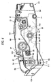
- a gear mechanism (not shown) for transmitting motive power from a motor (not shown) to respective rotation shafts of the agitator 44, the supply roller 40 and the development roller 41 is provided in a left surface of the casing 60.
- a cover 66 is fixed by screws 67 so that the gear mechanism is covered with the cover 66.
- the toner carried on the development roller 41 and charged with positive electricity is brought into contact with the photosensitive drum 29 so as to be opposite to the photosensitive drum 29 in accordance with the rotation of the development roller 41, the toner is supplied to the electrostatic latent image formed on the surface of the photosensitive drum 29, that is, on an exposure portion which is part of the surface of the photosensitive drum 29 evenly charged with positive electricity and which is exposed to the laser beam so that electric potential is lowered.
- the electrostatic latent image on the photosensitive drum 29 is visualized so that a toner image based on a reversal phenomenon is carried on the surface of the photosensitive drum 29.
- the fixing portion 21 is provided on the rear side of the process cartridge 20.
- the fixing portion 21 has a fixing frame 48, a heat roller 49, and a pressure roller 50.
- the heat roller 49 and the pressure roller 50 are provided in the fixing frame 48.
- the heat roller 49 has a metal tube, and a halogen lamp for heating the toner.
- the metal tube has a surface coated with a fluororesin.
- the halogen lamp is provided in the metal tube.
- the heat roller 49 is driven to rotate by motive power given from a motor not shown.
- the roller shaft guide portions 97 are formed as upper end edges of longitudinally central portions of the side walls 92 respectively.
- the roller shaft guide portions 97 are formed so as to extend obliquely downward from the front to the rear and then extend substantially horizontally flatly.
- a cleaning electrode 104 for applying a cleaning bias to the cleaning brush 33 is provided in the rear of the bearing member receiving groove 99 of the left side wall 92.
- the front lower connection portion 94 connects the front portions of the lower end edges of the pair of side walls 92 to each other.
- the front lower connection portion 94 has a registration roller storage portion 106 in which one (upper) of the registration rollers 14 is stored.
- the rear lower connection portion 95 provided below the bearing member receiving grooves 99 connects the rear portions of the lower end edges of the pair of side walls 92 to each other.
- the rear lower connection portion 95 has a transfer roller storage portion 107 in which the transfer roller 32 is stored. Roller bearings which are not shown but bear opposite end portions of the roller shaft 108 of the transfer roller 32 are provided in widthwise opposite end portions of the transfer roller storage portion 107 in the rear lower connection portion 95.
- the transfer roller 32 is rotatably supported by the rear lower connection portion 95 while the opposite end portions of the roller shaft 108 are borne by the roller bearings.
- the circular window holes 62 are formed in symmetric positions in the left and right side walls 60A of the casing 60 respectively so as to pierce the left and right side walls 60A.
- Figs. 6, 8, 9A and 9B show the configuration of the left window hole 62 and its vicinity but do not show the configuration of the right window hole 62 and its vicinity
- the configuration of the two window holes 62 and their vicinity in the casing 60 is roughly bilaterally symmetric to each other. Sealing members 63 of the same shape and window members 64 of the same shape are attached into the window holes 62 to thereby block the window holes 62 respectively.
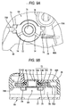
- a cylindrical alignment rib 70 (which serves as a "rib") having an inner diameter slightly larger than the diameter of the window hole 62 is formed so as to protrude to the outer surface side (upper side in Fig. 6) of the side wall 60A.
- Each sealing member 63 is made of an elastic material such as a moltopren and shaped like a toroid.
- the sealing member 63 is formed so that the outer diameter of the sealing member 63 is slightly larger than the inner diameter of the alignment rib 70 while the inner diameter of the sealing member 63 is slightly smaller than the inner diameter of the window hole 62.
- the sealing member 63 is embedded in the inside of the alignment rib 70 while compressed, so that the sealing member 63 is positioned radially.
- the window member 64 is made of a light-transmissive synthetic resin material such as polycarbonate.
- the window member 64 has a transmission portion 71 fitted into the window hole 62, and a flange portion 72 extending annularly outward in the radial direction of the transmission portion 71 or the window hole 62.
- the transmission portion 71 is a portion through which the detection light transmits.
- the transmission portion 71 protrudes cylindrically from the flange portion 72 toward the inside of the casing 60 (toward the lower side in Fig. 6).
- the outer diameter of the transmission portion 71 is set to be slightly smaller than the inner diameter of the window hole 62 and slightly larger than the inner diameter of the sealing member 63.
- a protrusion end surface 71A of the transmission portion 71 protrudes from the inner wall surface of the casing 60 toward the inside of the casing 60 in the condition that the window member 64 is combined with the window hole 62 (see Fig. 9B), so that the protrusion end surface 71A is cleaned with the wiper 65 provided in the toner storage chamber 39.
- a cylindrical bearing rib 76 (which serves as a "stopper") for supporting bearing members not shown but attached to opposite ends of the rotation shaft 61 of the agitator 44 is integrally formed on the side wall 60A of the casing 60 so as to protrude.
- One stopper nail 75A is integrally connected to the outer circumferential surface of the bearing rib 76. As shown in Fig. 9A, in the condition that the window member 64 is located in the engagement position, the outer circumferential surface of the bearing rib 76 restricts the stopped portion 73 fitted to the stopper nail 75A from rotating counterclockwise.
- a circular through-hole 77 through which the detection light passes is formed in the cover 66 for covering the left side surface of the casing 60 so as to be located in a position corresponding to the window hole 62.
- a flat plate-like locking piece 78 (which serves as a "locking member") extending in a direction perpendicular to the side wall 60A is integrally formed in the cover 66. The cover 66 is combined with the casing 60 after the window member 64 is combined with the casing 60. In this combination state, an end of the locking piece 78 is fitted to the stopped portion 73 located in the engagement position to thereby restrict the window member 64 from rotating from the engagement position to the non-engagement position.
- the window member 64 is further pushed in so that the transmission portion 71 is fitted into the window hole 62.
- the window member 64 is pushed in at an angle corresponding to the non-engagement position around the center axis of the window hole 62 as shown in Fig. 8, the stopped portions 73 can be prevented from interfering with the stopper nails 75A and 75B respectively. For this reason, the end of the transmission portion 71 can enter into the window hole 62.
- the window member 64 is rotated counterclockwise (in the direction of the arrow) in Fig. 8.
- the guide portion 72C of the flange portion 72 comes into frictional contact with the outer circumferential surface of the alignment rib 70, so that the posture of the window member 64 in the rotating operation is stabilized.
- a finger, a jig or the like can be put on the rotating operation rib 74 to smoothen the operation.
- the stopper nails 75A and 75B are provided near the window hole 62 in the casing 60 and the stopper nails 75A and 75B are fitted to the stopped portions 73 of the window member 64 to keep the window member 64 in a state in which the window hole 62 is blocked with the window member 64. Accordingly, the window member 64 can be attached easily compared with the case where the window member 64 is attached by ultrasonic welding, bonding or the like. Moreover, in the case where the window member 64 is damaged or stained with dust when the development cartridge 31 is to be re-used, the window member 64 can be exchanged for a new one easily compared with another attaching structure.
- the sealing member 63 is made of a annular member having elasticity, the sealing member 63 can be assembled easily compared with the case where a gel type sealing member or the like is used. Moreover, because the sealing member 63 is elastically deformed while compressed between the window member 64 and the circumferential edge portion of the window hole 62, sealing performance can be improved.
- sealing member 63 elastically adheres closely to the outer circumferential surface of the transmission portion 71 protruded from the flange portion 72, sealing performance can be improved.
- the window member 64 can rotate around the window hole 62 as its center and can be displaced between the engagement position and the non-engagement position by the operation of rotating the window member 64. Accordingly, when the window member 64 is rotated from the non-engagement position to the engagement position on the casing 60, the stopped portions 73 can be fitted to the stopper nails 75A and 75B. Accordingly, because it is unnecessary to flexibly deform the stopper nails 75A and 75B to attach the window member 64, the stopper nails can be prevented from being damaged by mistake.
- the window member 64 is rotated while the transmission portion 71 is fitted into the circular window hole 62, the posture of the window member 64 in the rotating operation can be stabilized to smoothen assembling.
- the bearing rib 76 as a stopper for restricting the window member 64 from rotating from the engagement position to a position reverse to the non-engagement position is provided in the casing 60. Accordingly, because the window member 64 is restricted from rotating any more when the window member 64 is rotated from the non-engagement position to the engagement position until the window member 64 reaches the engagement position, the attaching operation can be smoothened.
- the window member 64 can be kept stable with good balance.
- the window members 64 of the same shape are attached to the pair of window holes 62 provided in the casing 60, the number of kinds of parts can be reduced. In addition, the window members 64 corresponding to the window holes 62 can be prevented from being attached by mistake.
- the stopper nails can be fitted to the stopped portions of the window member so that the window member is held in a state in which the window hole is blocked with the window member. Accordingly, the window member can be attached easily compared with the case where the window member is attached by ultrasonic welding, bonding or the like.
- the sealing member is made of a annular member having elasticity. Accordingly, the sealing member can be assembled easily compared with the case where a gel type sealing member or the like is used. Moreover, because the sealing member is elastically deformed while compressed between the window member and the circumferential edge portion of the window hole, sealing performance can be improved.
- the rib is provided in the circumferential edge portion of the window hole so that the sealing member can be positioned radially. Accordingly, the assembling operation can be smoothened.
- the agitating member and the cleaning member are provided in the casing and the transmission portion protrudes toward the inside of the casing. Accordingly, the protrusion end surface of the transmission portion can be cleaned with the cleaning member surely.
- the window members of the same shape are attached to the pair of window holes provided in the casing. Accordingly, the number of kinds of parts can be reduced. In addition, the window members corresponding to the window holes can be prevented from being attached by mistake.
Landscapes
- Physics & Mathematics (AREA)
- General Physics & Mathematics (AREA)
- Electrophotography Configuration And Component (AREA)
- Dry Development In Electrophotography (AREA)
- Cameras Adapted For Combination With Other Photographic Or Optical Apparatuses (AREA)
Claims (17)
- Entwicklerkartusche (31), Folgendes aufweisend:ein Gehäuse (60), in dem ein Entwickler enthalten ist;eine Fensterloch (62);eine Anschlagplatte (75A, 75B), die nahe dem Fensterloch und zu diesem hin verlaufend vorgesehen ist; und ein Fensterelement (64) mit einem Übertragungsabschnitt (71), der Licht, das durch das Fensterloch hindurchgeht, überträgt, und ein in Anschlag zu bringender Abschnitt (73), mit dem die Anschlagplatte zusammengepasst wird, wobei das Fensterelement dadurch an einer Entfernung vom Fensterloch gehindert wird, dass die Anschlagplatte an den in Anschlag zu bringenden Abschnitt gepasst wird;dadurch gekennzeichnet, dass
das Fensterloch im Gehäuse vorgesehen ist, in dem der Entwickler enthalten ist;
das Fensterelement so an das Fensterloch angepasst ist, dass es sich um einen Mittelpunkt des Fensterlochs drehen kann; und
das Fensterelement entsprechend einer Drehbetätigung des Fensterelements zwischen einer Eingriffsstellung, in der der in Anschlag zu bringende Abschnitt an die Anschlagplatte angepasst ist, und einer Nicht-Eingriffsstellung, in der der in Anschlag zu bringende Abschnitt nicht an die Anschlagplatte angepasst ist, verlagert werden kann. - Entwicklerkartusche nach Anspruch 1, wobei die Anschlagplatte einstückig mit dem Gehäuse ausgebildet ist.
- Entwicklerkartusche nach einem der Ansprüche 1 und 2, ferner ein Dichtelement (63) aufweisend, das zwischen einem Umfangsrandabschnitt des Fensterlochs und dem Fensterelement angeordnet ist und eine Abdichtung dazwischen herstellt.
- Entwicklerkartusche nach Anspruch 3, wobei das Dichtelement aus einem ringförmigen Element mit Elastizität besteht, und
wobei das Dichtelement sich elastisch verformt, während es zwischen dem Fensterelement und dem Umfangsrandabschnitt des Fensterlochs komprimiert wird. - Entwicklerkartusche nach Anspruch 4, wobei das Fensterelement einen Flanschabschnitt (72) aufweist, der sich in Bezug auf das Fensterloch radial nach außen erstreckt, so dass er sich elastisch verformt, während das Dichtelement zwischen dem Flanschabschnitt und dem Umfangsrandabschnitt komprimiert wird, und
wobei die in Anschlag zu bringenden Abschnitte und die Anschlagplatten aneinander gepasst sind, während sie durch eine elastische Rückstellkraft des Dichtelements gegeneinander gedrückt werden. - Entwicklerkartusche nach Anspruch 5, wobei der Umfangsrandabschnitt mit einer Rippe (70) versehen ist, die das Dichtelement in radialer Richtung positioniert.
- Entwicklerkartusche nach Anspruch 5, wobei der Übertragungsabschnitt in das Fensterloch gepasst ist, während er vom Flanschabschnitt zum Fensterloch hin vorsteht, und wobei das Dichtelement nahe einer Außenumfangsfläche des Übertragungsabschnitts elastisch anliegt.
- Entwicklerkartusche nach Anspruch 1, wobei das Fensterloch einen kreisförmigen Querschnitt aufweist, und
wobei das Fensterelement so vorgesehen ist, dass es sich drehen kann, während der Getriebeabschnitt in das Fensterloch gepasst ist. - Entwicklerkartusche nach einem der Ansprüche 1 oder 8, wobei das Fensterelement mit einer Drehbetätigungsrippe (74) versehen ist, die in Bezug auf eine Mittelachse der Drehbetätigung radial vorsteht, wobei die Drehbetätigungsrippe an einer Außenfläche des Fensterelements vorgesehen ist.
- Entwicklerkartusche nach einem der Ansprüche 1, 8 oder 9, wobei das Gehäuse mit einem Anschlag (76) versehen ist, der das Fensterelement daran hindert, sich aus der Eingriffsstellung in eine Stellung zu drehen, die der Nicht-Eingriffsstellung entgegengerichtet ist.
- Entwicklerkartusche nach einem der Ansprüche 1, 8 bis 10, die ferner ein Riegelelement (78) aufweist, das verhindert, dass sich das Fensterelement aus der Eingriffsstellung in die Nicht-Eingriffsstellung dreht.
- Entwicklerkartusche nach Anspruch 11, wobei das Gehäuse an einer äußeren Oberfläche mit einem Getriebemechanismus und mit einer Abdeckung (66), die den Getriebemechanismus abdeckt, versehen ist, wobei die Abdeckung abnehmbar vorgesehen ist, und
wobei das Riegelelement einstückig mit der Abdeckung vorgesehen ist. - Entwicklerkartusche nach einem der Ansprüche 1, 8 - 12, wobei ein Paar Anschlagplatten für jedes der Fensterelement vorgesehen ist, und
wobei das Anschlagplattenpaar im Wesentlichen an punktsymmetrischen Positionen im Bezug auf das Zentrum des Fensterlochs vorgesehen ist. - Entwicklerkartusche nach einem der Ansprüche 1 - 13, wobei das Gehäuse in seinem Inneren mit einem Rührelement (44), das den Entwickler aufrührt, und einem Reinigungselement (65), der sich zusammen mit dem Rührelement bewegt, versehen ist, und
wobei der Übertragungsabschnitt so ausgebildet ist, dass er von einer inneren Wandoberfläche des Gehäuses nach innen vorsteht, und seine vorstehende Stirnfläche mit dem Reinigungselement gereinigt wird. - Entwicklerkartusche nach einem der Ansprüche 1 - 14, wobei das Fensterelement so vorgesehen ist, dass es von außerhalb des Gehäuses am Gehäuse angebracht werden kann.
- Entwicklerkartusche nach einem der Ansprüche 1-15, wobei das Gehäuse mit einem ein Paar Fensterlöcher versehen ist, durch die Erfassungslicht zum Erfassen von Entwicklerrestmengen hindurchgeht, und
wobei an den Fensterlöchern jeweils das Fensterelement mit der im Wesentlichen gleichen Gestalt montiert ist. - Bildgebungsvorrichtung, Folgendes aufweisend:einen Zufuhrabschnitt, der ein Blatt zuführt;einen Bildgebungsabschnitt, der mittels eines Entwicklers ein Bild auf dem vom Zufuhrabschnitt zugeführten Blatt bildet; undeine Entwicklerkartusche nach einem der vorangehenden Ansprüche.
Applications Claiming Priority (1)
| Application Number | Priority Date | Filing Date | Title |
|---|---|---|---|
| JP2004198507A JP4225248B2 (ja) | 2004-07-05 | 2004-07-05 | 現像剤カートリッジ及び画像形成装置 |
Publications (3)
| Publication Number | Publication Date |
|---|---|
| EP1615084A2 EP1615084A2 (de) | 2006-01-11 |
| EP1615084A3 EP1615084A3 (de) | 2006-06-07 |
| EP1615084B1 true EP1615084B1 (de) | 2007-11-07 |
Family
ID=35124361
Family Applications (1)
| Application Number | Title | Priority Date | Filing Date |
|---|---|---|---|
| EP05014472A Active EP1615084B1 (de) | 2004-07-05 | 2005-07-04 | Entwicklerkartusche und Bilderzeugungsgerät |
Country Status (6)
| Country | Link |
|---|---|
| US (1) | US7106982B2 (de) |
| EP (1) | EP1615084B1 (de) |
| JP (1) | JP4225248B2 (de) |
| CN (2) | CN100410818C (de) |
| AT (1) | ATE377781T1 (de) |
| DE (1) | DE602005003171T2 (de) |
Families Citing this family (10)
| Publication number | Priority date | Publication date | Assignee | Title |
|---|---|---|---|---|
| JP2006184515A (ja) * | 2004-12-27 | 2006-07-13 | Brother Ind Ltd | 現像装置及び画像形成装置 |
| US7869720B2 (en) * | 2007-01-10 | 2011-01-11 | Kyocera Mita Corporation | Consumable supplying member and toner container |
| JP4905689B2 (ja) * | 2007-02-21 | 2012-03-28 | 村田機械株式会社 | トナーカートリッジ |
| JP5762052B2 (ja) * | 2011-03-01 | 2015-08-12 | キヤノン株式会社 | 現像剤補給装置 |
| JP6004717B2 (ja) * | 2012-04-16 | 2016-10-12 | キヤノン株式会社 | 現像剤収容ユニット、現像剤カートリッジ、現像カートリッジ、およびプロセスカートリッジ |
| JP6341106B2 (ja) * | 2015-01-30 | 2018-06-13 | ブラザー工業株式会社 | 現像カートリッジ |
| JP6560918B2 (ja) * | 2015-07-10 | 2019-08-14 | シャープ株式会社 | 現像剤検出装置及び現像装置 |
| TWI727794B (zh) * | 2020-05-11 | 2021-05-11 | 上福全球科技股份有限公司 | 碳粉匣防錯裝置及碳粉匣 |
| CN113687581B (zh) * | 2020-05-19 | 2023-11-10 | 上福全球科技股份有限公司 | 碳粉匣及碳粉匣防错装置 |
| US12043808B2 (en) | 2021-12-28 | 2024-07-23 | Afton Chemical Corporation | Quaternary ammonium salt combinations for injector cleanliness |
Family Cites Families (14)
| Publication number | Priority date | Publication date | Assignee | Title |
|---|---|---|---|---|
| GB566182A (en) * | 1943-05-21 | 1944-12-18 | Stone J & Co Ltd | Improvements in hinged lights such as are used for ships' port holes |
| JPS5946391B2 (ja) * | 1977-11-30 | 1984-11-12 | 株式会社リコー | 磁気ブラシ現像装置 |
| JP3042108B2 (ja) | 1991-12-12 | 2000-05-15 | 松下電器産業株式会社 | トナー残量検出装置 |
| IT1268121B1 (it) * | 1993-10-15 | 1997-02-20 | Seiko Epson Corp | Apparecchiatura per la formazione di immagini |
| EP0665475A3 (de) | 1994-01-28 | 1997-01-29 | Canon Kk | Entwicklungsgerät, Prozesskartusche, Bilderzeugungsgerät und Montageverfahren der Prozesskartusche. |
| JP3651920B2 (ja) * | 1994-01-28 | 2005-05-25 | キヤノン株式会社 | 現像装置及びプロセスカートリッジ及び画像形成装置 |
| JPH09274384A (ja) | 1996-04-05 | 1997-10-21 | Canon Inc | 現像カートリッジ及びカラー画像形成装置 |
| JP2001100507A (ja) | 1999-09-30 | 2001-04-13 | Hitachi Ltd | 現像装置 |
| JP2002132034A (ja) | 2000-10-19 | 2002-05-09 | Canon Inc | 現像装置、プロセスカートリッジ及び画像形成装置 |
| JP2002311701A (ja) | 2001-04-11 | 2002-10-25 | Canon Inc | 画像形成装置及びプロセスカートリッジ |
| JP2003140457A (ja) * | 2001-11-07 | 2003-05-14 | Canon Inc | 現像装置及びプロセスカートリッジ及び画像形成装置 |
| JP4011411B2 (ja) | 2002-06-07 | 2007-11-21 | シャープ株式会社 | 印刷装置 |
| JP2004085649A (ja) | 2002-08-23 | 2004-03-18 | Canon Inc | プロセスカートリッジ |
| JP3926317B2 (ja) * | 2003-11-28 | 2007-06-06 | シャープ株式会社 | トナー残量検出装置、及びそれを備える画像形成装置 |
-
2004
- 2004-07-05 JP JP2004198507A patent/JP4225248B2/ja not_active Expired - Lifetime
-
2005
- 2005-07-01 CN CNB2005100824163A patent/CN100410818C/zh active Active
- 2005-07-04 EP EP05014472A patent/EP1615084B1/de active Active
- 2005-07-04 CN CN200520113062.XU patent/CN2826483Y/zh not_active Expired - Lifetime
- 2005-07-04 DE DE602005003171T patent/DE602005003171T2/de active Active
- 2005-07-04 AT AT05014472T patent/ATE377781T1/de not_active IP Right Cessation
- 2005-07-05 US US11/172,990 patent/US7106982B2/en active Active
Also Published As
| Publication number | Publication date |
|---|---|
| CN1722018A (zh) | 2006-01-18 |
| EP1615084A3 (de) | 2006-06-07 |
| DE602005003171D1 (de) | 2007-12-20 |
| JP2006018197A (ja) | 2006-01-19 |
| US7106982B2 (en) | 2006-09-12 |
| DE602005003171T2 (de) | 2008-09-04 |
| ATE377781T1 (de) | 2007-11-15 |
| EP1615084A2 (de) | 2006-01-11 |
| US20060002725A1 (en) | 2006-01-05 |
| CN100410818C (zh) | 2008-08-13 |
| CN2826483Y (zh) | 2006-10-11 |
| JP4225248B2 (ja) | 2009-02-18 |
Similar Documents
| Publication | Publication Date | Title |
|---|---|---|
| EP1615084B1 (de) | Entwicklerkartusche und Bilderzeugungsgerät | |
| US6823160B2 (en) | Developing device and image forming apparatus having a gear holder | |
| US7613414B2 (en) | Developing cartridge, process carriage, and image forming apparatus | |
| US6226476B1 (en) | Developing device holder having antenna contact mounting unit | |
| US7526225B2 (en) | Developing apparatus and assembly method of developing apparatus | |
| US7590371B2 (en) | Image carrying cartridge, process cartridge, and image-forming device | |
| JP4635701B2 (ja) | 現像カートリッジ、プロセスカートリッジおよび画像形成装置 | |
| JP4124153B2 (ja) | プロセスカートリッジおよび画像形成装置 | |
| JP4314529B2 (ja) | 現像カートリッジおよび画像形成装置 | |
| JP4284616B2 (ja) | 現像カートリッジ、プロセスカートリッジ及び画像形成装置 | |
| JP4385294B2 (ja) | 現像装置、プロセスカートリッジおよび画像形成装置 | |
| JP2006330620A (ja) | プロセスカートリッジおよび画像形成装置 | |
| US6181898B1 (en) | Developing apparatus | |
| JP2006039222A (ja) | プロセスカートリッジ及び画像形成装置 | |
| JP4385295B2 (ja) | 現像装置、プロセスカートリッジおよび画像形成装置 | |
| JP4123291B2 (ja) | プロセスカートリッジ、画像形成装置及び組み付け方法 | |
| JPH0619229A (ja) | プロセスカートリッジ | |
| JP2783726B2 (ja) | プロセスカートリッジ及び画像形成装置 | |
| JP2006349841A (ja) | プロセスカートリッジおよび画像形成装置 | |
| JP2006039216A (ja) | 画像形成装置、現像装置及びプロセスカートリッジ | |
| JP2006039434A (ja) | プロセスカートリッジおよび画像形成装置 |
Legal Events
| Date | Code | Title | Description |
|---|---|---|---|
| PUAI | Public reference made under article 153(3) epc to a published international application that has entered the european phase |
Free format text: ORIGINAL CODE: 0009012 |
|
| AK | Designated contracting states |
Kind code of ref document: A2 Designated state(s): AT BE BG CH CY CZ DE DK EE ES FI FR GB GR HU IE IS IT LI LT LU LV MC NL PL PT RO SE SI SK TR |
|
| AX | Request for extension of the european patent |
Extension state: AL BA HR MK YU |
|
| PUAL | Search report despatched |
Free format text: ORIGINAL CODE: 0009013 |
|
| AK | Designated contracting states |
Kind code of ref document: A3 Designated state(s): AT BE BG CH CY CZ DE DK EE ES FI FR GB GR HU IE IS IT LI LT LU LV MC NL PL PT RO SE SI SK TR |
|
| AX | Request for extension of the european patent |
Extension state: AL BA HR MK YU |
|
| 17P | Request for examination filed |
Effective date: 20061109 |
|
| AKX | Designation fees paid |
Designated state(s): AT BE BG CH CY CZ DE DK EE ES FI FR GB GR HU IE IS IT LI LT LU LV MC NL PL PT RO SE SI SK TR |
|
| GRAP | Despatch of communication of intention to grant a patent |
Free format text: ORIGINAL CODE: EPIDOSNIGR1 |
|
| GRAS | Grant fee paid |
Free format text: ORIGINAL CODE: EPIDOSNIGR3 |
|
| GRAA | (expected) grant |
Free format text: ORIGINAL CODE: 0009210 |
|
| AK | Designated contracting states |
Kind code of ref document: B1 Designated state(s): AT BE BG CH CY CZ DE DK EE ES FI FR GB GR HU IE IS IT LI LT LU LV MC NL PL PT RO SE SI SK TR |
|
| REG | Reference to a national code |
Ref country code: GB Ref legal event code: FG4D |
|
| REG | Reference to a national code |
Ref country code: IE Ref legal event code: FG4D |
|
| REG | Reference to a national code |
Ref country code: CH Ref legal event code: EP |
|
| REF | Corresponds to: |
Ref document number: 602005003171 Country of ref document: DE Date of ref document: 20071220 Kind code of ref document: P |
|
| PG25 | Lapsed in a contracting state [announced via postgrant information from national office to epo] |
Ref country code: SE Free format text: LAPSE BECAUSE OF FAILURE TO SUBMIT A TRANSLATION OF THE DESCRIPTION OR TO PAY THE FEE WITHIN THE PRESCRIBED TIME-LIMIT Effective date: 20080207 Ref country code: ES Free format text: LAPSE BECAUSE OF FAILURE TO SUBMIT A TRANSLATION OF THE DESCRIPTION OR TO PAY THE FEE WITHIN THE PRESCRIBED TIME-LIMIT Effective date: 20080218 Ref country code: CH Free format text: LAPSE BECAUSE OF FAILURE TO SUBMIT A TRANSLATION OF THE DESCRIPTION OR TO PAY THE FEE WITHIN THE PRESCRIBED TIME-LIMIT Effective date: 20071107 Ref country code: LI Free format text: LAPSE BECAUSE OF FAILURE TO SUBMIT A TRANSLATION OF THE DESCRIPTION OR TO PAY THE FEE WITHIN THE PRESCRIBED TIME-LIMIT Effective date: 20071107 Ref country code: NL Free format text: LAPSE BECAUSE OF FAILURE TO SUBMIT A TRANSLATION OF THE DESCRIPTION OR TO PAY THE FEE WITHIN THE PRESCRIBED TIME-LIMIT Effective date: 20071107 |
|
| NLV1 | Nl: lapsed or annulled due to failure to fulfill the requirements of art. 29p and 29m of the patents act | ||
| ET | Fr: translation filed | ||
| PG25 | Lapsed in a contracting state [announced via postgrant information from national office to epo] |
Ref country code: BG Free format text: LAPSE BECAUSE OF FAILURE TO SUBMIT A TRANSLATION OF THE DESCRIPTION OR TO PAY THE FEE WITHIN THE PRESCRIBED TIME-LIMIT Effective date: 20080207 Ref country code: SI Free format text: LAPSE BECAUSE OF FAILURE TO SUBMIT A TRANSLATION OF THE DESCRIPTION OR TO PAY THE FEE WITHIN THE PRESCRIBED TIME-LIMIT Effective date: 20071107 Ref country code: PL Free format text: LAPSE BECAUSE OF FAILURE TO SUBMIT A TRANSLATION OF THE DESCRIPTION OR TO PAY THE FEE WITHIN THE PRESCRIBED TIME-LIMIT Effective date: 20071107 Ref country code: LT Free format text: LAPSE BECAUSE OF FAILURE TO SUBMIT A TRANSLATION OF THE DESCRIPTION OR TO PAY THE FEE WITHIN THE PRESCRIBED TIME-LIMIT Effective date: 20071107 Ref country code: LV Free format text: LAPSE BECAUSE OF FAILURE TO SUBMIT A TRANSLATION OF THE DESCRIPTION OR TO PAY THE FEE WITHIN THE PRESCRIBED TIME-LIMIT Effective date: 20071107 Ref country code: IS Free format text: LAPSE BECAUSE OF FAILURE TO SUBMIT A TRANSLATION OF THE DESCRIPTION OR TO PAY THE FEE WITHIN THE PRESCRIBED TIME-LIMIT Effective date: 20080307 |
|
| REG | Reference to a national code |
Ref country code: CH Ref legal event code: PL |
|
| PG25 | Lapsed in a contracting state [announced via postgrant information from national office to epo] |
Ref country code: AT Free format text: LAPSE BECAUSE OF FAILURE TO SUBMIT A TRANSLATION OF THE DESCRIPTION OR TO PAY THE FEE WITHIN THE PRESCRIBED TIME-LIMIT Effective date: 20071107 |
|
| PG25 | Lapsed in a contracting state [announced via postgrant information from national office to epo] |
Ref country code: DK Free format text: LAPSE BECAUSE OF FAILURE TO SUBMIT A TRANSLATION OF THE DESCRIPTION OR TO PAY THE FEE WITHIN THE PRESCRIBED TIME-LIMIT Effective date: 20071107 Ref country code: CZ Free format text: LAPSE BECAUSE OF FAILURE TO SUBMIT A TRANSLATION OF THE DESCRIPTION OR TO PAY THE FEE WITHIN THE PRESCRIBED TIME-LIMIT Effective date: 20071107 |
|
| PG25 | Lapsed in a contracting state [announced via postgrant information from national office to epo] |
Ref country code: RO Free format text: LAPSE BECAUSE OF FAILURE TO SUBMIT A TRANSLATION OF THE DESCRIPTION OR TO PAY THE FEE WITHIN THE PRESCRIBED TIME-LIMIT Effective date: 20071107 Ref country code: BE Free format text: LAPSE BECAUSE OF FAILURE TO SUBMIT A TRANSLATION OF THE DESCRIPTION OR TO PAY THE FEE WITHIN THE PRESCRIBED TIME-LIMIT Effective date: 20071107 Ref country code: SK Free format text: LAPSE BECAUSE OF FAILURE TO SUBMIT A TRANSLATION OF THE DESCRIPTION OR TO PAY THE FEE WITHIN THE PRESCRIBED TIME-LIMIT Effective date: 20071107 |
|
| PLBE | No opposition filed within time limit |
Free format text: ORIGINAL CODE: 0009261 |
|
| STAA | Information on the status of an ep patent application or granted ep patent |
Free format text: STATUS: NO OPPOSITION FILED WITHIN TIME LIMIT |
|
| PG25 | Lapsed in a contracting state [announced via postgrant information from national office to epo] |
Ref country code: PT Free format text: LAPSE BECAUSE OF FAILURE TO SUBMIT A TRANSLATION OF THE DESCRIPTION OR TO PAY THE FEE WITHIN THE PRESCRIBED TIME-LIMIT Effective date: 20080407 |
|
| 26N | No opposition filed |
Effective date: 20080808 |
|
| PG25 | Lapsed in a contracting state [announced via postgrant information from national office to epo] |
Ref country code: GR Free format text: LAPSE BECAUSE OF FAILURE TO SUBMIT A TRANSLATION OF THE DESCRIPTION OR TO PAY THE FEE WITHIN THE PRESCRIBED TIME-LIMIT Effective date: 20080208 |
|
| PG25 | Lapsed in a contracting state [announced via postgrant information from national office to epo] |
Ref country code: FI Free format text: LAPSE BECAUSE OF FAILURE TO SUBMIT A TRANSLATION OF THE DESCRIPTION OR TO PAY THE FEE WITHIN THE PRESCRIBED TIME-LIMIT Effective date: 20071107 |
|
| PG25 | Lapsed in a contracting state [announced via postgrant information from national office to epo] |
Ref country code: MC Free format text: LAPSE BECAUSE OF NON-PAYMENT OF DUE FEES Effective date: 20080731 |
|
| PG25 | Lapsed in a contracting state [announced via postgrant information from national office to epo] |
Ref country code: EE Free format text: LAPSE BECAUSE OF FAILURE TO SUBMIT A TRANSLATION OF THE DESCRIPTION OR TO PAY THE FEE WITHIN THE PRESCRIBED TIME-LIMIT Effective date: 20071107 |
|
| PG25 | Lapsed in a contracting state [announced via postgrant information from national office to epo] |
Ref country code: IE Free format text: LAPSE BECAUSE OF NON-PAYMENT OF DUE FEES Effective date: 20080704 Ref country code: CY Free format text: LAPSE BECAUSE OF FAILURE TO SUBMIT A TRANSLATION OF THE DESCRIPTION OR TO PAY THE FEE WITHIN THE PRESCRIBED TIME-LIMIT Effective date: 20071107 |
|
| PG25 | Lapsed in a contracting state [announced via postgrant information from national office to epo] |
Ref country code: LU Free format text: LAPSE BECAUSE OF NON-PAYMENT OF DUE FEES Effective date: 20080704 Ref country code: HU Free format text: LAPSE BECAUSE OF FAILURE TO SUBMIT A TRANSLATION OF THE DESCRIPTION OR TO PAY THE FEE WITHIN THE PRESCRIBED TIME-LIMIT Effective date: 20080508 |
|
| PG25 | Lapsed in a contracting state [announced via postgrant information from national office to epo] |
Ref country code: TR Free format text: LAPSE BECAUSE OF FAILURE TO SUBMIT A TRANSLATION OF THE DESCRIPTION OR TO PAY THE FEE WITHIN THE PRESCRIBED TIME-LIMIT Effective date: 20071107 |
|
| REG | Reference to a national code |
Ref country code: FR Ref legal event code: PLFP Year of fee payment: 12 |
|
| REG | Reference to a national code |
Ref country code: FR Ref legal event code: PLFP Year of fee payment: 13 |
|
| REG | Reference to a national code |
Ref country code: FR Ref legal event code: PLFP Year of fee payment: 14 |
|
| PGFP | Annual fee paid to national office [announced via postgrant information from national office to epo] |
Ref country code: IT Payment date: 20220613 Year of fee payment: 18 Ref country code: GB Payment date: 20220606 Year of fee payment: 18 |
|
| PGFP | Annual fee paid to national office [announced via postgrant information from national office to epo] |
Ref country code: FR Payment date: 20220609 Year of fee payment: 18 |
|
| PGFP | Annual fee paid to national office [announced via postgrant information from national office to epo] |
Ref country code: DE Payment date: 20230531 Year of fee payment: 19 |
|
| GBPC | Gb: european patent ceased through non-payment of renewal fee |
Effective date: 20230704 |
|
| PG25 | Lapsed in a contracting state [announced via postgrant information from national office to epo] |
Ref country code: GB Free format text: LAPSE BECAUSE OF NON-PAYMENT OF DUE FEES Effective date: 20230704 |
|
| PG25 | Lapsed in a contracting state [announced via postgrant information from national office to epo] |
Ref country code: FR Free format text: LAPSE BECAUSE OF NON-PAYMENT OF DUE FEES Effective date: 20230731 |
|
| PG25 | Lapsed in a contracting state [announced via postgrant information from national office to epo] |
Ref country code: IT Free format text: LAPSE BECAUSE OF NON-PAYMENT OF DUE FEES Effective date: 20230704 |