EP1614563B1 - Stiffening beam for the passenger compartment of a motor vehicle for supporting an air distribution box of a climate control installation. - Google Patents
Stiffening beam for the passenger compartment of a motor vehicle for supporting an air distribution box of a climate control installation. Download PDFInfo
- Publication number
- EP1614563B1 EP1614563B1 EP05105101A EP05105101A EP1614563B1 EP 1614563 B1 EP1614563 B1 EP 1614563B1 EP 05105101 A EP05105101 A EP 05105101A EP 05105101 A EP05105101 A EP 05105101A EP 1614563 B1 EP1614563 B1 EP 1614563B1
- Authority
- EP
- European Patent Office
- Prior art keywords
- air
- beam according
- surface area
- members
- tips
- Prior art date
- Legal status (The legal status is an assumption and is not a legal conclusion. Google has not performed a legal analysis and makes no representation as to the accuracy of the status listed.)
- Not-in-force
Links
Images
Classifications
-
- B—PERFORMING OPERATIONS; TRANSPORTING
- B62—LAND VEHICLES FOR TRAVELLING OTHERWISE THAN ON RAILS
- B62D—MOTOR VEHICLES; TRAILERS
- B62D25/00—Superstructure or monocoque structure sub-units; Parts or details thereof not otherwise provided for
- B62D25/08—Front or rear portions
- B62D25/14—Dashboards as superstructure sub-units
-
- B—PERFORMING OPERATIONS; TRANSPORTING
- B60—VEHICLES IN GENERAL
- B60H—ARRANGEMENTS OF HEATING, COOLING, VENTILATING OR OTHER AIR-TREATING DEVICES SPECIALLY ADAPTED FOR PASSENGER OR GOODS SPACES OF VEHICLES
- B60H1/00—Heating, cooling or ventilating [HVAC] devices
- B60H1/00507—Details, e.g. mounting arrangements, desaeration devices
- B60H1/00514—Details of air conditioning housings
- B60H1/0055—Details of air conditioning housings the housing or parts thereof being integrated in other devices, e.g. dashboard
-
- B—PERFORMING OPERATIONS; TRANSPORTING
- B60—VEHICLES IN GENERAL
- B60H—ARRANGEMENTS OF HEATING, COOLING, VENTILATING OR OTHER AIR-TREATING DEVICES SPECIALLY ADAPTED FOR PASSENGER OR GOODS SPACES OF VEHICLES
- B60H1/00—Heating, cooling or ventilating [HVAC] devices
- B60H1/00507—Details, e.g. mounting arrangements, desaeration devices
- B60H1/00557—Details of ducts or cables
- B60H1/00564—Details of ducts or cables of air ducts
-
- B—PERFORMING OPERATIONS; TRANSPORTING
- B60—VEHICLES IN GENERAL
- B60H—ARRANGEMENTS OF HEATING, COOLING, VENTILATING OR OTHER AIR-TREATING DEVICES SPECIALLY ADAPTED FOR PASSENGER OR GOODS SPACES OF VEHICLES
- B60H1/00—Heating, cooling or ventilating [HVAC] devices
- B60H1/24—Devices purely for ventilating or where the heating or cooling is irrelevant
- B60H1/241—Devices purely for ventilating or where the heating or cooling is irrelevant characterised by the location of ventilation devices in the vehicle
- B60H1/242—Devices purely for ventilating or where the heating or cooling is irrelevant characterised by the location of ventilation devices in the vehicle located in the front area
Definitions
- the invention is in the field of heating, ventilation and / or air conditioning, in particular vehicle interior. It relates to a reinforcement beam of a vehicle interior organized to allow the circulation and selective distribution of air from such a facility.
- such beams are arranged to cooperate with, or even accommodate, subsidiary bodies of selective air distribution, such as splitters or the like, which tends to further increase the complexity of their organization to allow the assembly of these ancillary organs .
- the general difficulty to overcome lies in a compromise to be found between a structural simplicity of the beam, the structure of which should preferably intrinsically offer the desired mechanical characteristics for the reinforcement of the passenger compartment, an organization of the beam into an organ. capable of selectively conveying air flows from a heating, ventilation and / or air conditioning system, and the ability of the beam to provide easy mounting of various distribution and distribution of the intake air .
- the object of the present invention is to provide a reinforcement beam of a passenger compartment of a vehicle constituting a member selectively conveying air from a heating, ventilation and / or air conditioning system, which respond to the above-mentioned compromise.
- the present invention proposes in its entirety to organize the beam into a hollow monobloc element longitudinally extended in a constant direction having at its ends windows which provide a longitudinal insertion passage of selective distribution members of the air admitted to the inside the beam. These windows are formed at the ends of the beam to guide such an introduction passage along the general axis of extension of the beam, which is constant between its ends. These arrangements are such that the beam, extended transversely to the passenger compartment of the vehicle in a constant overall direction, is of a simple and robust structure in itself, which intrinsically offers the desired mechanical characteristics of resistance, while allowing the assembly easy by its ends of selective air distribution members.
- the body is preferably equipped at its ends with reinforcing ends and fixing the beam to the passenger compartment of the vehicle.
- One body structure will be understood as a structure in which the body constitutes a robust element of normally closed section, this body monobloc being likely to be composed of shells assembled together rigidly, and preferably and irreversibly irreversible by solidarization to give it an adequate strength, particularly by welding or the like.
- This one-piece body is preferably composed of at least two longitudinal elements joined together, by welding or the like in particular. To give this body an adequate strength, it is more particularly proposed to secure these elements along at least 80% of their contact surface to one another.
- Such boxes are likely to be of outer section substantially corresponding to that of the inner beam.
- caissons particularly provide various air circulation ducts inside the beam, being equipped with distributors or shutters for selectively directing the air admitted inside the beam through at least one mouth intake, to various corresponding outlet mouths arranged in correspondence through the walls of the beam.
- selective air distribution members, distributors or the like in particular are in turn capable of being introduced inside the beam through a global intake air intake from the installation, whose dimensions are large enough to be in correspondence with the cumulative dimensions of various outlets that includes the beam, which are defined to provide respective satisfactory air flow rates according to the ventilation zones of the passenger compartment which their are affected.
- such a beam with a wall thickness of the order of 2 mm to 3.5 mm provides a first natural frequency of a minimum of 130 Hz, with a high resistance to rupture, which meet the requirements in the field.
- the constituent material of the beam is capable of being indifferently of steel, aluminum or an alloy, a composite material, or even a laminated material.
- Such characteristics of the beam offer the possibility of its installation in the vehicle by fixing it only by its ends, without any additional piece of reinforcement, such as crutch type or connection with the deck.
- the one-piece structure of the beam reinforced at its ends by the end pieces makes it possible to place the different mouths that the beam comprises with significant longitudinal and transverse positioning tolerances, which favor a comfortable adaptability of the beam for any vehicle interior. , without having to modify the general organization of its structure.
- the beam of the present invention is a hollow reinforcing beam for vehicle interior.
- This beam also constitutes a member through which air circulates from a heating, ventilation and / or air conditioning installation, and for this purpose comprises at least one air inlet and a plurality exhaust air vents are allowed.
- such a beam is mainly recognizable in that it consists of a monobloc body longitudinally extended in a constant direction.
- This body has at its ends windows for the longitudinal introduction of selective distribution members of the air admitted inside the beam.
- This body is further equipped with reinforcing ends and fixing the beam to the passenger compartment of the vehicle.
- the one-piece body is in particular composed of at least two longitudinal elements joined to each other, particularly by welding.
- This welding is for example carried out by laser beam, electron beam or by capacitor discharge, or other similar process.
- the end pieces are preferably extended in the longitudinal direction of the beam overlapping the lateral air outlet openings, for structural reasons.
- These tips have openings facing the lateral air outlet openings of the beam.
- the end pieces may for example be organized in clamps.
- these tips are each composed of a pair of brackets connected to each other at their free edges, and preferably comprise a closing plate of the ends of the beam. This plate is advantageously provided with centering members at the end of the beam, and fasteners of the end pieces on a supporting structure of the passenger compartment.
- the beam is in particular of polygonal section, rectangular in particular. Note that this section is likely to vary along the length of the beam to provide necking passages of the vehicle, such as a steering column and / or airbag.
- end caps cover an area of the beam having a mouth
- they are provided with at least one window disposed opposite said mouth to allow the passage of air.
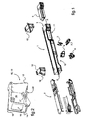
- a reinforcement beam 1 of a vehicle interior is organized for the circulation through air from a heating installation, ventilation and / or air conditioning of the vehicle. More particularly, this beam 1 is arranged to accommodate at least one box 2.3 forming a selective air distribution module, or 4.5 even distributors, such as shutters or the like it receives via turntables linkage 6.7.
- This beam 1 is longitudinally extended in a constant direction and is open at its ends to provide windows 8, 9 through which are introduced caissons 2,3 for mounting inside the beam 1.
- the orientation of these windows 8,9 relative to the general axis A of extension of the beam 1 is such that it allows the passage of the caissons 2,3 through the windows 8,9 along this axis A extension of the beam 1. It will also be noted that the introduction of the caissons 2, 3 by the ends of the beam 1 is made possible for caissons 2, 3 which are longitudinally extended in a consistent manner, thanks to the constancy of the extension of the beam 1 between its ends.
- the section of the beam 1 is generally rectangular.
- the cross-section of the beam 1 is capable of varying, both in conformation and dimension, without necessarily inducing a variation in its general direction of extension, in particular for forming narrows 10, 11 for the passage of a column of direction of the vehicle or airbag.
- the ends of the beam 1 are equipped with end pieces 12, 13 for reinforcing and fixing the beam 1 on a supporting structure of the passenger compartment of the vehicle, and in particular on the amounts that the latter comprises.
- These tips 12, 13 are each generally shaped in a couple of brackets 14,15 connected to each other by their free edges.
- a plate 16 closing the ends of the beam 1 is disposed at the end of the brackets 14,15 of each of the end pieces 12,13, and comprises centering members 17 on the outer faces of the beam 1.
- a wing 18 for fixing the 12.13 end caps on the carrier structure of the passenger compartment is provided on the rear face of this plate 16.
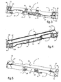
- the beam 1 has on its faces various mouths. Note that the architecture of the beam 1 proposed by the invention allows to relatively freely position these mouths along the sides of the beam, to adapt the latter to any vehicle without significantly altering its structure, nor affect to its intrinsic qualities of mechanical strength sought.
- an air intake opening 21 is formed substantially in the middle zone of the lower face 22 of the beam 1.
- This air intake opening 21 is indicative of a dimension having an area of between 1, 2 dm2 and 2,2 dm2. It should be noted that such an area is to be estimated with regard to current values in the field for airflows of the order of 500 kg / h to 700 kg / h. Such a dimension is likely to be used for the introduction of at least one distributor 4.5 after introduction of the caissons 2,3 component of the air distribution module in particular. It will be noted at this stage of the description that the area of the vents of the beam, taken individually, is between 0.17 times and 0.15 times the area of the inlet mouth 21. air.
- the beam is characterized in that the area of the air outlet mouths 23, 24, 26, taken individually, is between 0.17 times and 0.25 times the area of the air inlet mouth 21 .
- Evacuation mouths 23 for right and left rear aeration respectively are provided at the corresponding ends of the lower face 22 of the beam 1.
- exhaust vents 24 for lateral ventilation respectively right and left are provided at the corresponding ends of the front face 25 of the beam 1.
- Evacuation vents 26 for central ventilation are provided in the central zone of the front face 25 of the beam 1.
- evacuation mouths 27 for right and left demisting respectively are provided at the corresponding ends of the upper face 28 of the beam 1. These mouths 27 each have an area of between 0.05 and 0.2 times the area cumulative exhaust vents 27,29 for defrosting and / or soft diffusion 29 and for defogging 27.
- Evacuation and / or gentle diffusion vents 29 are provided in the median zone of the rear face 30 of the beam 1. These mouths 29 have a cumulative surface area of the order of between 0.8 and 0. , 95 times the cumulative area of vents 27,29 of air evacuation for defrosting and / or soft diffusion (29) and for defogging (27).
- the beam 1 has an outer section of the order of 1.81 dm2 and a maximum inner section of the order of 1.64 dm2, for a thickness of its faces of the order of 3 mm.
- the minimum inner section of the latter is of the order of 1 dm2.
- the cumulative area of the air outlet mouths 23,24,26,27,29 is of the order of 6.3 dm2 for respectively a distribution of these surfaces of the order of 0.962 dm2 for mouths 23 d. rear aeration, of the order of 0.956 dm2 for the vents 24 of lateral aeration, of the order of 0.814 dm2 for the vents 26 of central ventilation, of the order of 0.318 dm2 for defogger vents 27, and of the order of 1.438 dm2 for defrost vents 29 and / or soft diffusion.
- the cumulative area of mouths in the faces of the beam relative to the overall area of these mouths is of the order of 44% for the lower face of the beam, of the order of 28% for the front face, of the order of 5% for the upper face and of the order of 23% for the rear face.
- the internal section of the beam 1 to the right of the tapered 10,11 is in particular between 0.25 times and 0.7 times the area of the air inlet mouth. More specifically, in the case of the presence of a lateral vent 24 alone, the section of the beam 1 to the right of the constriction 10,11 is of the order of 0.25 times the area of the mouth of air intake 21, while in the case where this lateral ventilation mouth 24 is associated with other evacuation mouths, such as rear aeration 23 and lateral demister 27, this section of the beam 1 is of the order of 0.7 times the area of the air inlet. It will be understood that these dimensions of beam section are given as an indication, and must where appropriate take into account the size of an air distribution box or the like disposed within the beam.
- the sum of the areas of the vents 27,29 for evacuation and defrost discharge is between 0.7 dm2 and 1.6 dm2. It will be understood that these dimensions are to be taken into account with regard to a usual air flow rate in the range of 320 kg / h to 500 kg / h.
Abstract
Description
L'invention est du domaine des installations de chauffage, de ventilation et/ou de climatisation, pour habitacle de véhicule notamment. Elle a pour objet une poutre de renfort d'un habitacle de véhicule organisée pour permettre la circulation et la distribution sélective d'air en provenance d'une telle installation.The invention is in the field of heating, ventilation and / or air conditioning, in particular vehicle interior. It relates to a reinforcement beam of a vehicle interior organized to allow the circulation and selective distribution of air from such a facility.
On connaît des installations de chauffage, de ventilation et/ou de climatisation pour habitacle de véhicule qui exploite la présence d'une poutre de renfort de l'habitacle pour véhiculer l'air distribué par l'installation. Ces poutres sont organisées soit pour loger des conduits en provenance de l'installation, soit de manière à constituer elles-mêmes des conduits de distribution d'air. On pourra par exemple se reporter aux documents,
Le problème posé réside dans l'organisation générale de la poutre dont la résistance mécanique, qui constitue sa fonction première, ne doit pas être altérée par son agencement en organe de circulation et de distribution d'air. Il ressort d'une manière générale que ce compromis à trouver tend à diminuer les performances structurelles de la poutre, en raison de la présence d'ouvertures qui constituent des faiblesses mécaniques, de l'utilisation nécessaire en trop grande partie des matériaux peu résistants, matériaux plastiques notamment, ou encore en raison de modalités d'assemblage discontinus entre des éléments constitutifs de la poutre, qui créent des faiblesses structurelles.The problem lies in the general organization of the beam whose mechanical strength, which is its primary function, should not be altered by its arrangement as a circulating member and air distribution. It generally appears that this compromise to be found tends to reduce the structural performance of the beam, due to the presence of openings that are mechanical weaknesses, the use of too much of the weak materials, plastic materials in particular, or because of discontinuous assembly methods between components of the beam, which create structural weaknesses.
En outre, de telles poutres sont agencées pour coopérer avec, voire loger des organes annexes de distribution sélective d'air, tels que des répartiteurs ou analogues, ce qui tend à accroître encore la complexité de leur organisation pour permettre le montage de ces organes annexes.In addition, such beams are arranged to cooperate with, or even accommodate, subsidiary bodies of selective air distribution, such as splitters or the like, which tends to further increase the complexity of their organization to allow the assembly of these ancillary organs .
Il en ressort que la difficulté générale à surmonter réside dans un compromis à trouver entre une simplicité structurelle de la poutre, dont la structure doit de préférence offrir intrinsèquement les caractéristiques mécaniques recherchées pour le renfort de l'habitacle, une organisation de la poutre en organe susceptible de véhiculer sélectivement des flux d'air en provenance d'une installation de chauffage, de ventilation et/ou de climatisation, et la faculté de la poutre à offrir un montage aisé de divers organes de répartition et de distribution de l'air admis.It emerges that the general difficulty to overcome lies in a compromise to be found between a structural simplicity of the beam, the structure of which should preferably intrinsically offer the desired mechanical characteristics for the reinforcement of the passenger compartment, an organization of the beam into an organ. capable of selectively conveying air flows from a heating, ventilation and / or air conditioning system, and the ability of the beam to provide easy mounting of various distribution and distribution of the intake air .
Le but de la présente invention est de proposer une poutre de renfort d'un habitacle d'un véhicule constituant un organe véhiculant de manière sélective de l'air en provenance d'une installation de chauffage, de ventilation et/ou de climatisation, qui réponde au compromis susvisé.The object of the present invention is to provide a reinforcement beam of a passenger compartment of a vehicle constituting a member selectively conveying air from a heating, ventilation and / or air conditioning system, which respond to the above-mentioned compromise.
La présente invention propose dans sa globalité d'organiser la poutre en un élément monobloc creux longitudinalement étendu suivant une direction constante comportant à ses extrémités des fenêtres qui offrent un passage d'introduction longitudinale d'organes de distribution sélective de l'air admis à l'intérieur de la poutre. Ces fenêtres sont ménagées aux bouts de la poutre pour orienter un tel passage d'introduction suivant l'axe général d'extension de la poutre, qui est constant entre ses extrémités. Ces dispositions sont telles que la poutre, étendue transversalement à l'habitacle du véhicule suivant une direction globale constante, est d'une structure simple et robuste en elle-même, qui offre intrinsèquement les caractéristiques mécaniques recherchées de résistance, tout en permettant le montage aisé par ses extrémités d'organes de distribution sélective d'air. Le corps est de préférence équipé à ses extrémités d'embouts de renfort et de fixation de la poutre à l'habitacle du véhicule.The present invention proposes in its entirety to organize the beam into a hollow monobloc element longitudinally extended in a constant direction having at its ends windows which provide a longitudinal insertion passage of selective distribution members of the air admitted to the inside the beam. These windows are formed at the ends of the beam to guide such an introduction passage along the general axis of extension of the beam, which is constant between its ends. These arrangements are such that the beam, extended transversely to the passenger compartment of the vehicle in a constant overall direction, is of a simple and robust structure in itself, which intrinsically offers the desired mechanical characteristics of resistance, while allowing the assembly easy by its ends of selective air distribution members. The body is preferably equipped at its ends with reinforcing ends and fixing the beam to the passenger compartment of the vehicle.
On comprendra par structure monobloc du corps une structure dans laquelle le corps constitue un élément robuste de section normalement fermée, ce corps monobloc étant susceptible d'être composé de coquilles assemblées entre elles de manière rigide, voire et de préférence de manière irréversible par solidarisation pour lui conférer une robustesse idoine, par soudage notamment ou analogue.One body structure will be understood as a structure in which the body constitutes a robust element of normally closed section, this body monobloc being likely to be composed of shells assembled together rigidly, and preferably and irreversibly irreversible by solidarization to give it an adequate strength, particularly by welding or the like.
Ce corps monobloc est préférentiellement composé d'au moins deux éléments longitudinaux solidarisés entre eux, par soudage ou analogue notamment. Pour conférer à ce corps une robustesse idoine, il est plus particulièrement proposé de solidariser ces éléments le long d'au moins 80 % de leur surface de contact l'un à l'autre.This one-piece body is preferably composed of at least two longitudinal elements joined together, by welding or the like in particular. To give this body an adequate strength, it is more particularly proposed to secure these elements along at least 80% of their contact surface to one another.
Il est notamment visé par l'invention de permettre l'introduction longitudinale à l'intérieur de la poutre d'un module de distribution sélective d'air subdivisé en caissons longitudinaux cloisonnés respectivement droit et gauche. De tels caissons sont susceptibles d'être de section extérieure sensiblement correspondante à celle intérieure de la poutre. On comprendra que de tels caissons ménagent notamment divers conduits de circulation d'air à l'intérieur de la poutre, en étant équipés de répartiteurs ou volets pour diriger sélectivement l'air admis à l'intérieur de la poutre à travers au moins une bouche d'admission, vers diverses bouches d'évacuation correspondantes ménagées en correspondance à travers les parois de la poutre.It is particularly intended by the invention to allow the longitudinal introduction into the beam of a selective air distribution module subdivided into longitudinal chambers respectively partitioned right and left. Such boxes are likely to be of outer section substantially corresponding to that of the inner beam. It will be understood that such caissons particularly provide various air circulation ducts inside the beam, being equipped with distributors or shutters for selectively directing the air admitted inside the beam through at least one mouth intake, to various corresponding outlet mouths arranged in correspondence through the walls of the beam.
On notera que des organes de distribution sélective d'air, répartiteurs ou analogues notamment, sont quant à eux susceptibles d'être introduits à l'intérieur de la poutre à travers une bouche globale d'admission de l'air en provenance de l'installation, dont les dimensions sont suffisamment importantes pour être en correspondance avec les dimensions cumulées de diverses bouches d'évacuation que comporte la poutre, qui sont définies pour offrir des débits d'air respectifs satisfaisants selon les zones d'aération de l'habitacle qui leurs sont affectées.It will be noted that selective air distribution members, distributors or the like in particular, are in turn capable of being introduced inside the beam through a global intake air intake from the installation, whose dimensions are large enough to be in correspondence with the cumulative dimensions of various outlets that includes the beam, which are defined to provide respective satisfactory air flow rates according to the ventilation zones of the passenger compartment which their are affected.
A titre indicatif, une telle poutre d'une paroi d'épaisseur de l'ordre de 2 mm à 3,5 mm offre une première fréquence propre d'un minimum de 130 Hz, avec une résistance importante à la rupture, qui répondent aux exigences dans le domaine.As an indication, such a beam with a wall thickness of the order of 2 mm to 3.5 mm provides a first natural frequency of a minimum of 130 Hz, with a high resistance to rupture, which meet the requirements in the field.
On notera que le matériau constitutif de la poutre est susceptible d'être indifféremment de l'acier, de l'aluminium ou un alliage, un matériau composite, voire un matériau stratifié.It will be noted that the constituent material of the beam is capable of being indifferently of steel, aluminum or an alloy, a composite material, or even a laminated material.
De telles caractéristiques de la poutre offrent la possibilité de son installation dans le véhicule en ne la fixant que par ses extrémités, sans aucune pièce additionnelle de renfort, telle que du type béquille ou liaison avec le tablier.Such characteristics of the beam offer the possibility of its installation in the vehicle by fixing it only by its ends, without any additional piece of reinforcement, such as crutch type or connection with the deck.
Par ailleurs, la structure monobloc de la poutre renforcée à ses extrémités par les embouts permet de placer les différentes bouches que comporte la poutre avec des tolérances importantes de positionnement longitudinal et transversal, qui favorisent une adaptabilité confortable de la poutre pour un quelconque habitacle de véhicule, sans avoir à modifier l'organisation générale de sa structure.Furthermore, the one-piece structure of the beam reinforced at its ends by the end pieces makes it possible to place the different mouths that the beam comprises with significant longitudinal and transverse positioning tolerances, which favor a comfortable adaptability of the beam for any vehicle interior. , without having to modify the general organization of its structure.
Plus particulièrement, la poutre de la présente invention est une poutre creuse de renfort pour habitacle de véhicule. Cette poutre constitue en outre un organe à travers lequel circule de l'air en provenance d'une installation de chauffage, de ventilation et/ou de climatisation, et comporte à cet effet au moins une bouche d'admission d'air et une pluralité de bouches d'évacuation de l'air admis.More particularly, the beam of the present invention is a hollow reinforcing beam for vehicle interior. This beam also constitutes a member through which air circulates from a heating, ventilation and / or air conditioning installation, and for this purpose comprises at least one air inlet and a plurality exhaust air vents are allowed.
Selon la présente invention, une telle poutre est principalement reconnaissable en ce qu'elle est constituée d'un corps monobloc longitudinalement étendu suivant une direction constante. Ce corps comporte à ses extrémités des fenêtres pour l'introduction longitudinale d'organes de distribution sélective de l'air admis à l'intérieur de la poutre. Ce corps est en outre équipé d'embouts de renfort et de fixation de la poutre à l'habitacle du véhicule.According to the present invention, such a beam is mainly recognizable in that it consists of a monobloc body longitudinally extended in a constant direction. This body has at its ends windows for the longitudinal introduction of selective distribution members of the air admitted inside the beam. This body is further equipped with reinforcing ends and fixing the beam to the passenger compartment of the vehicle.
On notera que le corps monobloc est notamment composé d'au moins deux éléments longitudinaux solidarisés entre eux, par soudage notamment. Ce soudage est par exemple réalisé par faisceau laser, faisceau d'électrons ou par décharge de condensateur, ou autre procédé analogue.It will be noted that the one-piece body is in particular composed of at least two longitudinal elements joined to each other, particularly by welding. This welding is for example carried out by laser beam, electron beam or by capacitor discharge, or other similar process.
Les embouts sont de préférence prolongés dans le sens longitudinal de la poutre en recouvrement des ouvertures de sortie d'air latérales, pour des raisons structurelles. Ces embouts présentent des ouvertures en regard des ouvertures latérales de sortie d'air de la poutre. Les embouts peuvent par exemple être organisés en colliers de serrage. Selon une forme préférée de réalisation, ces embouts sont chacun composés d'un couple d'équerres reliées l'une à l'autre à leurs bords libres, et comportent de préférence une platine de fermeture des extrémités de la poutre. Cette platine est avantageusement pourvue d'organes de centrage en bout de la poutre, et d'organes de fixation des embouts sur une structure porteuse de l'habitacle.The end pieces are preferably extended in the longitudinal direction of the beam overlapping the lateral air outlet openings, for structural reasons. These tips have openings facing the lateral air outlet openings of the beam. The end pieces may for example be organized in clamps. According to a preferred embodiment, these tips are each composed of a pair of brackets connected to each other at their free edges, and preferably comprise a closing plate of the ends of the beam. This plate is advantageously provided with centering members at the end of the beam, and fasteners of the end pieces on a supporting structure of the passenger compartment.
La poutre est notamment de section polygonale, rectangulaire notamment. On notera que cette section est susceptible de varier suivant la longueur de la poutre pour ménager des rétreints de passage d'organes du véhicule, tels qu'une colonne de direction et/ou un airbag.The beam is in particular of polygonal section, rectangular in particular. Note that this section is likely to vary along the length of the beam to provide necking passages of the vehicle, such as a steering column and / or airbag.
Dans le cas où les embouts couvrent une zone de la poutre comportant une bouche, ceux-ci sont dotés d'au moins une fenêtre disposée en regard de cette bouche pour autoriser le passage de l'air.In the case where the end caps cover an area of the beam having a mouth, they are provided with at least one window disposed opposite said mouth to allow the passage of air.
La présente invention sera mieux comprise à la lecture de la description qui va en être faite d'une forme préférée de réalisation, en relation avec les figures des planches annexées, dans lesquelles :
- La
fig.1 est une illustration en perspective éclatée d'une poutre de renfort de la présente invention, environnée d'accessoires de distribution d'air qu'elle est destinée à loger. - La
fig.2 est une illustration en perspective d'un embout que comporte la poutre représentée sur lafig.1 . - La
fig.3 est une illustration en perspective d'une poutre représentée sur lafig.1 , sur laquelle sont visibles ses faces frontale et inférieure. - La
fig.4 est une illustration en perspective d'une poutre représentée sur lafig.1 , sur laquelle sont visibles ses faces frontale et supérieure. - La
fig.5 est une illustration en perspective d'une poutre représentée sur lafig.1 , sur laquelle sont visibles ses faces arrière et supérieure.
- The
fig.1 is an exploded perspective illustration of a reinforcing beam of the present invention, surrounded by air distribution accessories that it is intended to house. - The
fig.2 is a perspective illustration of a tip that includes the beam shown on thefig.1 . - The
fig.3 is a perspective illustration of a beam shown on thefig.1 , on which are visible its front and bottom faces. - The
fig.4 is a perspective illustration of a beam shown on thefig.1 , on which are visible its front and upper faces. - The
fig.5 is a perspective illustration of a beam shown on thefig.1 , on which are visible its rear and upper faces.
Sur la
On relèvera que l'orientation de ces fenêtres 8,9 par rapport à l'axe A général d'extension de la poutre 1 est telle qu'elle permet le passage des caissons 2,3 à travers les fenêtres 8,9 suivant cet axe A d'extension de la poutre 1. On notera aussi que l'introduction des caissons 2,3 par les extrémités de la poutre 1 est rendue possible pour des caissons 2,3 qui sont longitudinalement étendus de manière conséquente, grâce à la constance de l'extension de la poutre 1 entre ses extrémités. Sur l'exemple préféré de réalisation illustrée, la section de la poutre 1 est globalement rectangulaire. On comprendra que la section de la poutre 1 est susceptible de varier, tant en conformation qu'en dimension sans pour autant induire une variation de sa direction générale d'extension, notamment pour former des rétreints 10,11 de passage d'une colonne de direction du véhicule ou d'un airbag.It will be noted that the orientation of these
En se reportant par ailleurs sur la
Les équerres 14,15 composant les embouts 12,13 étant susceptibles de recouvrir des bouches 23,24 que comporte la poutre 1, des fenêtres 19,20 sont ménagées dans les embouts 12,13 de manière à être disposées en regard sur ces bouches 23,24 pour autoriser le passage de l'air hors de la poutre 1.The
Sur les
Sur la
Des bouches 23 d'évacuation pour l'aération arrière respectivement droite et gauche sont ménagées aux extrémités correspondantes de la face inférieure 22 de la poutre 1.
En se reportant par ailleurs sur la
Des bouches 26 d'évacuation pour l'aération centrale sont ménagées en zone médiane de la face frontale 25 de la poutre 1.Referring also to the
Evacuation vents 26 for central ventilation are provided in the central zone of the
En se reportant par ailleurs sur la
Des bouches 29 d'évacuation pour le dégivrage et/ou la diffusion douce sont ménagées en zone médiane de la face arrière 30 de la poutre 1. Ces bouches 29 sont d'une superficie cumulée de l'ordre comprise entre 0,8 et 0,95 fois la superficie cumulée des bouches 27,29 d'évacuation d'air pour le dégivrage et/ou la diffusion douce (29) et pour le désembuage (27).Referring also to the
Evacuation and / or gentle diffusion vents 29 are provided in the median zone of the
On relèvera que selon une forme de réalisation préférée et à titre indicatif, la poutre 1 présente une section extérieure de l'ordre de 1,81 dm2 et une section intérieure maximale de l'ordre de 1,64 dm2, pour une épaisseur de ses faces de l'ordre de 3 mm. Dans le cas où la poutre 1 ne distribue de l'air que pour l'aération avant, la section intérieure minimale de cette dernière est de l'ordre de 1 dm2.It will be noted that according to a preferred embodiment and as an indication, the
La superficie cumulée des bouches 23,24,26,27,29 d'évacuation d'air est de l'ordre de 6,3 dm2 pour respectivement une répartition de ces surfaces de l'ordre de 0,962 dm2 pour les bouches 23 d'aération arrière, de l'ordre de 0,956 dm2 pour les bouches 24 d'aération latérales, de l'ordre de 0,814 dm2 pour les bouches 26 d'aération centrale, de l'ordre de 0,318 dm2 pour les bouches 27 de désembuage, et de l'ordre de 1,438 dm2 pour les bouches 29 de dégivrage et/ou la diffusion douce.The cumulative area of the
Par ailleurs, la superficie cumulée des bouches ménagées dans les faces de la poutre par rapport à la superficie globale de ces bouches, est de l'ordre de 44% pour la face inférieure de la poutre, de l'ordre de 28% pour la face frontale, de l'ordre de 5% pour la face supérieure et de l'ordre de 23% pour la face arrière.Furthermore, the cumulative area of mouths in the faces of the beam relative to the overall area of these mouths, is of the order of 44% for the lower face of the beam, of the order of 28% for the front face, of the order of 5% for the upper face and of the order of 23% for the rear face.
La section interne de la poutre 1 au droit des rétreints 10,11 est notamment comprise entre 0,25 fois et 0,7 fois la superficie de la bouche d'admission d'air. Plus précisément, dans le cas de la présence d'une bouche d'aération latérale 24 seule, la section de la poutre 1 au droit du rétreint 10,11 est de l'ordre de 0,25 fois la superficie de la bouche d'admission d'air 21, tandis que dans le cas où à cette bouche d'aération latérale 24 est adjoint d'autres bouches d'évacuation, telles que d'aération arrière 23 et de désembuage latéral 27, cette section de la poutre 1 est de l'ordre de 0,7 fois la superficie de la bouche d'admission d'air. On comprendra que ces dimensions de section de poutre sont données à titre indicatif, et doivent le cas échéant prendre en compte l'encombrement d'un caisson de distribution d'air ou analogue disposé à l'intérieur de la poutre.The internal section of the
la somme des superficies des bouches 27,29 d'évacuation pour le désembuage et le dégivrage est comprise entre 0,7 dm2 et 1,6 dm2. On comprendra que ces dimensions sont à prendre en compte au regard d'un débit d'air habituel dans le domaine de l'ordre de 320 kg/h à 500 kg/h.the sum of the areas of the
Sur l'exemple de réalisation illustré, le module de distribution sélective d'air est composé de deux caissons 2 et 3. Un premier caisson est lui-même composé de trois éléments 31, 32, 33, dont deux éléments longitudinaux 31 et 32 et un élément de cloisonnement intérieur 33. Un deuxième caisson 3 est quant à lui constitué d'un élément monobloc. Le procédé d'assemblage de la poutre avec les organes de distribution sélective d'air consiste notamment à effectuer les étapes successives suivantes :
- -) solidariser l'un à l'autre, par soudage notamment, les éléments constitutifs de la poutre 1, pour former le corps monobloc.
- -) Introduire le ou les organes de
distribution sélective d'air - -) Fixer à la poutre 1, par vissage notamment, les organes de
distribution sélective d'air caisson 2. - -) Introduire et fixer le ou les répartiteurs 4,5 à l'intérieur de la poutre à travers la bouche d'admission 21. On notera que ces répartiteurs sont susceptibles de comprendre des répartiteurs affectés et fixés aux caissons (non représentés) et des répartiteurs affectés à la bouche d'admission d'air 21 et fixés directement sur la poutre 1, par l'intermédiaire des platines de
liaison
- -) secure to one another, particularly by welding, the constituent elements of the
beam 1, to form the one-piece body. - -) Introduce the selective air distribution member (s) 2,3 longitudinally inside the
beam 1, through thewindows - -) Attach to the
beam 1, especially by screwing, the selectiveair distribution members box 2. - -) Introduce and fix the 4.5 or distributors 4.5 inside the beam through the
inlet mouth 21. Note that these distributors are likely to include assigned distributors and attached to the boxes (not shown) and distributors assigned to theair intake opening 21 and fixed directly to thebeam 1, through the connectingplates
Plus particulièrement sur l'exemple de réalisation illustré, le procédé d'assemblage d'une poutre de la présente invention, avec des organes de distribution sélective d'air tels qu'illustrés, comprend les étapes successives consistant à :
- -) introduire longitudinalement un premier élément longitudinal 31 du caisson à l'intérieur de la poutre à travers son extrémité correspondante. On notera que cet élément 31 est celui comportant le cas échéant un rétreint de passage d'un organe du véhicule, colonne de direction notamment.
- -) Enfiler par glissement le deuxième élément longitudinal 32 sur le premier élément 31, pour son introduction à l'intérieur de la poutre.
- -) Placer l'élément de cloisonnement 33 en bout des éléments longitudinaux 31 et 32.
- -) Fixer depuis l'extérieur de la poutre 1, par vissage notamment ou analogue, les éléments longitudinaux 31,32 à travers des orifices que comporte la poutre 1, pour assembler ces éléments longitudinaux 31,32 entre eux et pour les solidariser à la poutre 1, tout en réalisant l'étanchéité entre ces différents éléments 21,32 assemblés.
- -) Introduire et fixer le deuxième caisson à l'intérieur de la poutre, à partir de son extrémité opposée à la précédente.
- -) Le cas échéant, introduire et fixer des répartiteurs à l'intérieur de l'un au moins des caissons, à travers la bouche d'admission 21.
- -) Introduire des répartiteurs médians 4,5 à l'intérieur de la poutre 1, à travers la bouche d'admission 21. On notera que ces répartiteurs médians 4,5 sont avantageusement fixés à la poutre par l'intermédiaire des platines de
liaison 6et 7.
- -) longitudinally introduce a first longitudinal member 31 of the box inside the beam through its corresponding end. It will be noted that this element 31 is the one comprising, where appropriate, a constriction of passage of a vehicle member, including a steering column.
- -) Slidingly threading the second longitudinal member 32 on the first member 31, for its introduction into the beam.
- -) Place the partitioning element 33 at the end of the longitudinal elements 31 and 32.
- -) Fixing from the outside of the
beam 1, by screwing in particular or the like, the longitudinal elements 31, 32 through holes in thebeam 1, to assemble these longitudinal elements 31, 32 between them and to secure them to thebeam 1, while achieving the seal between thesevarious elements 21,32 assembled. - -) Introduce and fix the second box inside the beam, from its end opposite to the previous one.
- -) Where appropriate, insert and fasten splitter boxes inside at least one of the boxes, through the
inlet port 21. - -) Introduce median distributors 4.5 inside the
beam 1, through theintake port 21. It should be noted that these median distributors 4.5 are advantageously attached to the beam through the connectingplates
Claims (19)
- Hollow beam (1) for reinforcing the cockpit of a vehicle, this beam (1) constituting a member through which air originating from a heating, ventilation and/or air conditioning system flows, and for this purpose comprising at least one air intake opening (21) and a plurality of outlet openings (23, 24, 26, 27, 29) for discharging the admitted air, and being made up of an integral body stretching longitudinally in a constant direction and which is equipped at its ends with tips (12, 13) for reinforcing the beam (1) and fixing it to the cockpit of the vehicle, characterized in that at its ends it comprises windows (8, 9) for the longitudinal introduction of members for the selective distribution of the air admitted into the beam (1).
- Beam according to Claim 1, characterized in that the integral body is made up of at least two longitudinal elements secured to one another.
- Beam according to Claim 2, characterized in that the elements that make up the body are secured to one another along at least 80% of their contact area.
- Beam according to either one of Claims 2 and 3, characterized in that the elements that make up the body are secured by welding.
- Beam according to any one of the preceding claims, characterized in that the members for the selective distribution of air are introduced into the beam through an overall air intake opening for air originating from the system.
- Beam according to any one of the preceding claims, characterized in that the tips (12, 13) are organized as clamping collars.
- Beam according to any one of the preceding claims, characterized in that, with the tips (12, 13) covering a region of the beam (1) comprising an opening (23, 24), these tips are provided with at least one window (19, 20) positioned facing this opening (23, 24) so as to allow air to pass.
- Beam according to either one of Claims 6 and 7, characterized in that the tips (12, 13) are each made up of a pair of brackets (14, 15) connected to one another at their free edges.
- Beam according to any one of the preceding claims, characterized in that the tips (12, 13) comprise a plate (16) to close off the ends of the beam (1), this plate being provided with centering members (17) for centering it on this beam (1) and with members (18) for fixing the tips (12, 13) to a bearing structure of the cockpit.
- Beam according to any one of the preceding claims, characterized in that it is of polygonal cross section.
- Beam according to any one of the preceding claims, characterized in that it is of a cross section that can vary along its length so as to form narrower regions (10, 11) for the passage of parts of the vehicle.
- Beam according to any one of the preceding claims, characterized in that the air intake opening (21) is of a size that exhibits a surface area of between 1.2 dm2 and 2.2 dm2.
- Beam according to any one of the preceding claims, characterized in that the air intake opening (21) is formed in a central region of the underside (22) of the beam (1).
- Beam according to any one of the preceding claims; characterized in that the surface area of the air outlet openings (23, 24, 26), considered individually, is between 0.17 times and 0.25 times the surface area of the air intake opening (21).
- Beam according to Claim 11, characterized in that the internal cross section of the beam (1) at the narrower regions (10, 11) is between 0.25 times and 0.7 times the surface area of the air intake opening.
- Beam according to Claim 14, characterized in that the sum of the surface areas of the outlet openings (27, 29) for demisting and deicing is between 0.7 dm2 and 1.6 dm2.
- Beam according to Claim 16, characterized in that outlet openings (27) for demisting the right and the left respectively are formed at the corresponding ends of the top surface (28) of the beam (1) and each have a surface area of between 0.05 and 0.2 times the combined surface area of the air outlet openings (27, 29) for deicing and/or gentle diffusion (29) and for demisting (27).
- Beam according to Claim 16, characterized in that outlet openings (29) for deicing and/or gentle diffusion are formed in the central region of the rear face (30) of the beam (1) and have a surface area of between 0.8 and 0.95 times the combined surface area of the air outlet openings (27, 29) for deicing and/or gentle diffusion (29) and for demisting (27).
- Method of assembling a beam with members for the selective distribution of air according to any one of Claims 2 to 18, characterized in that it consists in performing the following successive steps:- securing the constituent elements of the beam (1) to one another to form the integral body.- introducing the member or members (2, 3) for the selective distribution of air longitudinally into the beam (1), through the respective end windows (8, 9) formed therein.- fixing the members (2, 3) for the selective distribution of air to the beam (1), particularly by screwing.- introducing and fixing splitters (4, 5) inside the beam (1) through the intake opening (21).
Applications Claiming Priority (1)
| Application Number | Priority Date | Filing Date | Title |
|---|---|---|---|
| FR0407560A FR2872742B1 (en) | 2004-07-07 | 2004-07-07 | REINFORCING BEAM OF A HOUSE ORGANIZED FOR THE RECEPTION OF A SELECTIVE AIR DISTRIBUTION MODULE OF A HEATING, VENTILATION AND / OR AIR CONDITIONING INSTALLATION |
Publications (3)
| Publication Number | Publication Date |
|---|---|
| EP1614563A2 EP1614563A2 (en) | 2006-01-11 |
| EP1614563A3 EP1614563A3 (en) | 2006-05-17 |
| EP1614563B1 true EP1614563B1 (en) | 2008-03-26 |
Family
ID=34940141
Family Applications (1)
| Application Number | Title | Priority Date | Filing Date |
|---|---|---|---|
| EP05105101A Not-in-force EP1614563B1 (en) | 2004-07-07 | 2005-06-10 | Stiffening beam for the passenger compartment of a motor vehicle for supporting an air distribution box of a climate control installation. |
Country Status (7)
| Country | Link |
|---|---|
| US (1) | US7413243B2 (en) |
| EP (1) | EP1614563B1 (en) |
| JP (1) | JP2006021760A (en) |
| AT (1) | ATE390307T1 (en) |
| DE (1) | DE602005005561T2 (en) |
| ES (1) | ES2303186T3 (en) |
| FR (1) | FR2872742B1 (en) |
Families Citing this family (8)
| Publication number | Priority date | Publication date | Assignee | Title |
|---|---|---|---|---|
| FR2936751B1 (en) * | 2008-10-02 | 2011-08-05 | Valeo Vision Sas | PROJECTOR FOR A MOTOR VEHICLE MOUNTED ON A REINFORCING BEAM HAVING AN AIR CIRCULATION CHANNEL. |
| US20100274667A1 (en) * | 2009-04-24 | 2010-10-28 | Nexidia Inc. | Multimedia access |
| US20110215614A1 (en) * | 2010-02-25 | 2011-09-08 | Ayyakannu Mani | Lightweight cross-car beam and method of constructing a structural member |
| JP2016030559A (en) * | 2014-07-30 | 2016-03-07 | ヤンマー株式会社 | Work vehicle |
| US10766339B2 (en) * | 2017-01-26 | 2020-09-08 | Ford Global Technologies, Llc | Vehicle structural air duct |
| JP6958388B2 (en) * | 2018-01-27 | 2021-11-02 | マツダ株式会社 | Vehicle air conditioner |
| CN108482072B (en) * | 2018-03-08 | 2020-09-29 | 潍柴动力股份有限公司 | Platformized air duct |
| CN115158488B (en) * | 2022-06-27 | 2023-11-14 | 重庆长安汽车股份有限公司 | Seat mounting beam assembly integrated with ventilating duct and automobile |
Family Cites Families (22)
| Publication number | Priority date | Publication date | Assignee | Title |
|---|---|---|---|---|
| DE4232847A1 (en) * | 1992-09-30 | 1994-03-31 | Audi Ag | Dashboard for a motor vehicle |
| DE4239171C1 (en) | 1992-11-21 | 1993-10-14 | Daimler Benz Ag | Transverse beam forming air conduit under windscreen - directs air entering from below for nearly its full length and has bottom sloping downwards to open water outlet |
| SE512389C2 (en) | 1997-04-29 | 2000-03-13 | Volvo Ab | Arrangement for vehicle body structure |
| US5934744A (en) * | 1997-10-01 | 1999-08-10 | General Motors Corporation | Cross car structural beam |
| US6045444A (en) | 1998-08-28 | 2000-04-04 | General Motors Corporation | Compact automotive air conditioning module |
| DE19926636A1 (en) * | 1999-06-11 | 2000-12-14 | Porsche Ag | Cockpit cross member in a motor vehicle |
| FR2799413B1 (en) | 1999-10-06 | 2002-07-12 | Valeo Climatisation | HEATING AND / OR AIR CONDITIONING SYSTEM FOR A MOTOR VEHICLE, INCLUDING AN AIR DISTRIBUTION SYSTEM |
| JP2001246922A (en) * | 2000-03-06 | 2001-09-11 | Unipres Corp | Cross member with air-conditioning duct for automobile |
| WO2001068391A2 (en) | 2000-03-17 | 2001-09-20 | Magna Interior Systems, Inc. | A dashboard car duct with integrated mode doors and hvac module |
| AU2002210476A1 (en) * | 2000-09-07 | 2002-03-22 | Behr Gmbh And Co. | Structural part for a motor vehicle |
| DE10045347A1 (en) * | 2000-09-14 | 2002-03-28 | Behr Gmbh & Co | Arrangement of a housing of a heating and / or air conditioning system |
| FR2834271B1 (en) * | 2001-12-27 | 2004-02-20 | Sai Automotive Allibert Ind | DASHBOARD STRUCTURAL ASSEMBLY AND METHOD FOR MAKING SAME |
| US6644722B2 (en) * | 2002-01-17 | 2003-11-11 | Bayer Corporation | Molded article having a rigid support and a rigid hollow member |
| JP4239594B2 (en) * | 2002-04-10 | 2009-03-18 | 株式会社デンソー | Air conditioning duct structure for vehicles |
| FR2841506B1 (en) * | 2002-06-26 | 2004-08-27 | Faurecia Interieur Ind | DASHBOARD ASSEMBLY AND VEHICLE COMPRISING THE ASSEMBLY |
| US6912863B2 (en) * | 2002-08-30 | 2005-07-05 | Denso Corporation | Cooling structure for cooling vehicle electronic unit |
| DE60310339T2 (en) * | 2002-11-01 | 2007-05-10 | Calsonic Kansei Corp. | Cross member and manufacturing process |
| US7128360B2 (en) * | 2002-12-10 | 2006-10-31 | Delphi Technologies, Inc. | Structural hybrid attachment system and method |
| US20040108744A1 (en) * | 2002-12-10 | 2004-06-10 | Scheib Chales J. | Structural hybrid attachment system |
| US6688680B1 (en) * | 2002-12-17 | 2004-02-10 | Bayer Polymers Llc | Molded cross vehicle beam |
| JP2004203244A (en) * | 2002-12-25 | 2004-07-22 | Collins & Aikman Corp | Defroster nozzle |
| US7264295B2 (en) * | 2005-07-26 | 2007-09-04 | Visteon Global Technologies, Inc. | Vehicle cockpit attachment structure with integrated plastic composite functional molded features |
-
2004
- 2004-07-07 FR FR0407560A patent/FR2872742B1/en active Active
-
2005
- 2005-06-10 ES ES05105101T patent/ES2303186T3/en active Active
- 2005-06-10 DE DE602005005561T patent/DE602005005561T2/en active Active
- 2005-06-10 AT AT05105101T patent/ATE390307T1/en not_active IP Right Cessation
- 2005-06-10 EP EP05105101A patent/EP1614563B1/en not_active Not-in-force
- 2005-07-06 JP JP2005197471A patent/JP2006021760A/en active Pending
- 2005-07-06 US US11/175,496 patent/US7413243B2/en active Active
Also Published As
| Publication number | Publication date |
|---|---|
| FR2872742B1 (en) | 2008-12-05 |
| ES2303186T3 (en) | 2008-08-01 |
| DE602005005561T2 (en) | 2009-04-30 |
| JP2006021760A (en) | 2006-01-26 |
| US7413243B2 (en) | 2008-08-19 |
| US20060199491A1 (en) | 2006-09-07 |
| FR2872742A1 (en) | 2006-01-13 |
| ATE390307T1 (en) | 2008-04-15 |
| DE602005005561D1 (en) | 2008-05-08 |
| EP1614563A3 (en) | 2006-05-17 |
| EP1614563A2 (en) | 2006-01-11 |
Similar Documents
| Publication | Publication Date | Title |
|---|---|---|
| EP1614563B1 (en) | Stiffening beam for the passenger compartment of a motor vehicle for supporting an air distribution box of a climate control installation. | |
| CA2674264C (en) | Section of aircraft fuselage and aircraft including one such section | |
| EP2059440A1 (en) | Panel assembly and method of erecting a panel assembly | |
| EP2981450A1 (en) | Composite floor and motor vehicle comprising such a floor | |
| EP2621766B1 (en) | Deformable lower windscreen cross-member | |
| EP1580098A1 (en) | Vehicle roof, and vehicle with such a roof | |
| FR3055612A1 (en) | COMPARTMENTED STRUCTURE FOR THE ACOUSTIC TREATMENT AND DEFROSTING OF AN AIRCRAFT NACELLE AND AN AIRCRAFT NACELLE INCORPORATING THE SAID STRUCTURE | |
| EP1630075B1 (en) | Vehicle body having improved dynamic behaviour | |
| FR2772682A1 (en) | Modular dashboard for vehicle | |
| EP3880541B1 (en) | Dashboard body with a lacunary structure and integrated fluid circulation ducts | |
| EP1614562B1 (en) | Air routing and distribution module for the climatisation installation in a motor vehicle. | |
| FR2799412A1 (en) | Heating or air conditioning installation for motor vehicles, uses rigid structure that combines reinforcement of the vehicle structure with integral air delivery ducts and housings for heater, fan and evaporator | |
| EP1195316B1 (en) | Vehicle dashboard, and vehicle equipped with such a dashboard | |
| FR3059625B1 (en) | FIXING FENCE OF AT LEAST ONE FUNCTIONAL ELEMENT AND VEHICLE COMPRISING SUCH A CLOSING | |
| FR2881708A1 (en) | Stiffening girder for cab interior of vehicle, has opening arranged across girder wall in shrinking zone, where opening is closed by closing unit equipped of reception unit for receiving structural unit of vehicle and air stream unit | |
| EP1470990B1 (en) | Dashboard for automotive vehicle | |
| EP3409558B1 (en) | Air-diffusing sheath for aeration system, especially for a railway vehicle | |
| EP3744606B1 (en) | Ventilation device for a vehicle comprising at least one acoustic absorption element and associated vehicle | |
| EP3333050B1 (en) | Attachment by half-shells of a cross-member of a driver's compartment of a vehicle | |
| FR2876655A1 (en) | Front cross member for motor vehicle, has tubular beam comprising upper and lower shells and four bars to reinforce beam, where bars/shells are made of stratified material having plastic layer situated between two metallic layers | |
| FR2831511A1 (en) | Utility vehicle cabin comprises lattice work structure forming chassis on which protection, insulation and bodywork elements are fixed | |
| EP3090925B1 (en) | Windshield bay cross member for a motor vehicle and associated motor vehicle | |
| FR3036357A1 (en) | AIR CONDITIONING SYSTEM FOR RAIL TYPE VEHICLE | |
| EP1306248B1 (en) | Unit for a vehicle comprising a conduit and a inner liner panel, method for mounting such an assembly and inner liner panel | |
| WO2015189503A1 (en) | Front portion of the structure of a motor vehicle |
Legal Events
| Date | Code | Title | Description |
|---|---|---|---|
| PUAI | Public reference made under article 153(3) epc to a published international application that has entered the european phase |
Free format text: ORIGINAL CODE: 0009012 |
|
| AK | Designated contracting states |
Kind code of ref document: A2 Designated state(s): AT BE BG CH CY CZ DE DK EE ES FI FR GB GR HU IE IS IT LI LT LU MC NL PL PT RO SE SI SK TR |
|
| AX | Request for extension of the european patent |
Extension state: AL BA HR LV MK YU |
|
| PUAL | Search report despatched |
Free format text: ORIGINAL CODE: 0009013 |
|
| AK | Designated contracting states |
Kind code of ref document: A3 Designated state(s): AT BE BG CH CY CZ DE DK EE ES FI FR GB GR HU IE IS IT LI LT LU MC NL PL PT RO SE SI SK TR |
|
| AX | Request for extension of the european patent |
Extension state: AL BA HR LV MK YU |
|
| RIC1 | Information provided on ipc code assigned before grant |
Ipc: B62D 25/14 20060101ALI20060328BHEP Ipc: B60H 1/00 20060101AFI20050929BHEP |
|
| 17P | Request for examination filed |
Effective date: 20060915 |
|
| AKX | Designation fees paid |
Designated state(s): AT BE BG CH CY CZ DE DK EE ES FI FR GB GR HU IE IS IT LI LT LU MC NL PL PT RO SE SI SK TR |
|
| 17Q | First examination report despatched |
Effective date: 20070219 |
|
| GRAP | Despatch of communication of intention to grant a patent |
Free format text: ORIGINAL CODE: EPIDOSNIGR1 |
|
| GRAS | Grant fee paid |
Free format text: ORIGINAL CODE: EPIDOSNIGR3 |
|
| GRAA | (expected) grant |
Free format text: ORIGINAL CODE: 0009210 |
|
| AK | Designated contracting states |
Kind code of ref document: B1 Designated state(s): AT BE BG CH CY CZ DE DK EE ES FI FR GB GR HU IE IS IT LI LT LU MC NL PL PT RO SE SI SK TR |
|
| REG | Reference to a national code |
Ref country code: GB Ref legal event code: FG4D Free format text: NOT ENGLISH |
|
| REG | Reference to a national code |
Ref country code: CH Ref legal event code: EP Ref country code: IE Ref legal event code: FG4D Free format text: LANGUAGE OF EP DOCUMENT: FRENCH |
|
| REF | Corresponds to: |
Ref document number: 602005005561 Country of ref document: DE Date of ref document: 20080508 Kind code of ref document: P |
|
| PG25 | Lapsed in a contracting state [announced via postgrant information from national office to epo] |
Ref country code: FI Free format text: LAPSE BECAUSE OF FAILURE TO SUBMIT A TRANSLATION OF THE DESCRIPTION OR TO PAY THE FEE WITHIN THE PRESCRIBED TIME-LIMIT Effective date: 20080326 |
|
| REG | Reference to a national code |
Ref country code: ES Ref legal event code: FG2A Ref document number: 2303186 Country of ref document: ES Kind code of ref document: T3 |
|
| PG25 | Lapsed in a contracting state [announced via postgrant information from national office to epo] |
Ref country code: AT Free format text: LAPSE BECAUSE OF FAILURE TO SUBMIT A TRANSLATION OF THE DESCRIPTION OR TO PAY THE FEE WITHIN THE PRESCRIBED TIME-LIMIT Effective date: 20080326 |
|
| NLV1 | Nl: lapsed or annulled due to failure to fulfill the requirements of art. 29p and 29m of the patents act | ||
| PG25 | Lapsed in a contracting state [announced via postgrant information from national office to epo] |
Ref country code: SI Free format text: LAPSE BECAUSE OF FAILURE TO SUBMIT A TRANSLATION OF THE DESCRIPTION OR TO PAY THE FEE WITHIN THE PRESCRIBED TIME-LIMIT Effective date: 20080326 Ref country code: PL Free format text: LAPSE BECAUSE OF FAILURE TO SUBMIT A TRANSLATION OF THE DESCRIPTION OR TO PAY THE FEE WITHIN THE PRESCRIBED TIME-LIMIT Effective date: 20080326 |
|
| REG | Reference to a national code |
Ref country code: IE Ref legal event code: FD4D |
|
| PG25 | Lapsed in a contracting state [announced via postgrant information from national office to epo] |
Ref country code: SK Free format text: LAPSE BECAUSE OF FAILURE TO SUBMIT A TRANSLATION OF THE DESCRIPTION OR TO PAY THE FEE WITHIN THE PRESCRIBED TIME-LIMIT Effective date: 20080326 Ref country code: SE Free format text: LAPSE BECAUSE OF FAILURE TO SUBMIT A TRANSLATION OF THE DESCRIPTION OR TO PAY THE FEE WITHIN THE PRESCRIBED TIME-LIMIT Effective date: 20080626 Ref country code: PT Free format text: LAPSE BECAUSE OF FAILURE TO SUBMIT A TRANSLATION OF THE DESCRIPTION OR TO PAY THE FEE WITHIN THE PRESCRIBED TIME-LIMIT Effective date: 20080901 |
|
| PG25 | Lapsed in a contracting state [announced via postgrant information from national office to epo] |
Ref country code: NL Free format text: LAPSE BECAUSE OF FAILURE TO SUBMIT A TRANSLATION OF THE DESCRIPTION OR TO PAY THE FEE WITHIN THE PRESCRIBED TIME-LIMIT Effective date: 20080326 Ref country code: RO Free format text: LAPSE BECAUSE OF FAILURE TO SUBMIT A TRANSLATION OF THE DESCRIPTION OR TO PAY THE FEE WITHIN THE PRESCRIBED TIME-LIMIT Effective date: 20080326 |
|
| BERE | Be: lapsed |
Owner name: VALEO SYSTEMES THERMIQUES Effective date: 20080630 |
|
| PG25 | Lapsed in a contracting state [announced via postgrant information from national office to epo] |
Ref country code: IS Free format text: LAPSE BECAUSE OF FAILURE TO SUBMIT A TRANSLATION OF THE DESCRIPTION OR TO PAY THE FEE WITHIN THE PRESCRIBED TIME-LIMIT Effective date: 20080726 |
|
| PG25 | Lapsed in a contracting state [announced via postgrant information from national office to epo] |
Ref country code: LT Free format text: LAPSE BECAUSE OF FAILURE TO SUBMIT A TRANSLATION OF THE DESCRIPTION OR TO PAY THE FEE WITHIN THE PRESCRIBED TIME-LIMIT Effective date: 20080326 Ref country code: MC Free format text: LAPSE BECAUSE OF NON-PAYMENT OF DUE FEES Effective date: 20080630 Ref country code: IE Free format text: LAPSE BECAUSE OF FAILURE TO SUBMIT A TRANSLATION OF THE DESCRIPTION OR TO PAY THE FEE WITHIN THE PRESCRIBED TIME-LIMIT Effective date: 20080326 Ref country code: DK Free format text: LAPSE BECAUSE OF FAILURE TO SUBMIT A TRANSLATION OF THE DESCRIPTION OR TO PAY THE FEE WITHIN THE PRESCRIBED TIME-LIMIT Effective date: 20080326 |
|
| PLBE | No opposition filed within time limit |
Free format text: ORIGINAL CODE: 0009261 |
|
| STAA | Information on the status of an ep patent application or granted ep patent |
Free format text: STATUS: NO OPPOSITION FILED WITHIN TIME LIMIT |
|
| 26N | No opposition filed |
Effective date: 20081230 |
|
| PG25 | Lapsed in a contracting state [announced via postgrant information from national office to epo] |
Ref country code: BE Free format text: LAPSE BECAUSE OF NON-PAYMENT OF DUE FEES Effective date: 20080630 |
|
| PG25 | Lapsed in a contracting state [announced via postgrant information from national office to epo] |
Ref country code: EE Free format text: LAPSE BECAUSE OF FAILURE TO SUBMIT A TRANSLATION OF THE DESCRIPTION OR TO PAY THE FEE WITHIN THE PRESCRIBED TIME-LIMIT Effective date: 20080326 Ref country code: BG Free format text: LAPSE BECAUSE OF FAILURE TO SUBMIT A TRANSLATION OF THE DESCRIPTION OR TO PAY THE FEE WITHIN THE PRESCRIBED TIME-LIMIT Effective date: 20080626 |
|
| PG25 | Lapsed in a contracting state [announced via postgrant information from national office to epo] |
Ref country code: CY Free format text: LAPSE BECAUSE OF FAILURE TO SUBMIT A TRANSLATION OF THE DESCRIPTION OR TO PAY THE FEE WITHIN THE PRESCRIBED TIME-LIMIT Effective date: 20080326 |
|
| REG | Reference to a national code |
Ref country code: CH Ref legal event code: PL |
|
| GBPC | Gb: european patent ceased through non-payment of renewal fee |
Effective date: 20090610 |
|
| PG25 | Lapsed in a contracting state [announced via postgrant information from national office to epo] |
Ref country code: CH Free format text: LAPSE BECAUSE OF NON-PAYMENT OF DUE FEES Effective date: 20090630 Ref country code: LI Free format text: LAPSE BECAUSE OF NON-PAYMENT OF DUE FEES Effective date: 20090630 |
|
| PG25 | Lapsed in a contracting state [announced via postgrant information from national office to epo] |
Ref country code: GB Free format text: LAPSE BECAUSE OF NON-PAYMENT OF DUE FEES Effective date: 20090610 |
|
| PG25 | Lapsed in a contracting state [announced via postgrant information from national office to epo] |
Ref country code: LU Free format text: LAPSE BECAUSE OF NON-PAYMENT OF DUE FEES Effective date: 20080610 Ref country code: HU Free format text: LAPSE BECAUSE OF FAILURE TO SUBMIT A TRANSLATION OF THE DESCRIPTION OR TO PAY THE FEE WITHIN THE PRESCRIBED TIME-LIMIT Effective date: 20080927 |
|
| PG25 | Lapsed in a contracting state [announced via postgrant information from national office to epo] |
Ref country code: TR Free format text: LAPSE BECAUSE OF FAILURE TO SUBMIT A TRANSLATION OF THE DESCRIPTION OR TO PAY THE FEE WITHIN THE PRESCRIBED TIME-LIMIT Effective date: 20080326 |
|
| PG25 | Lapsed in a contracting state [announced via postgrant information from national office to epo] |
Ref country code: GR Free format text: LAPSE BECAUSE OF FAILURE TO SUBMIT A TRANSLATION OF THE DESCRIPTION OR TO PAY THE FEE WITHIN THE PRESCRIBED TIME-LIMIT Effective date: 20080627 |
|
| REG | Reference to a national code |
Ref country code: FR Ref legal event code: PLFP Year of fee payment: 12 |
|
| REG | Reference to a national code |
Ref country code: FR Ref legal event code: PLFP Year of fee payment: 13 |
|
| PGFP | Annual fee paid to national office [announced via postgrant information from national office to epo] |
Ref country code: CZ Payment date: 20170522 Year of fee payment: 13 Ref country code: FR Payment date: 20170630 Year of fee payment: 13 Ref country code: DE Payment date: 20170614 Year of fee payment: 13 |
|
| PGFP | Annual fee paid to national office [announced via postgrant information from national office to epo] |
Ref country code: IT Payment date: 20170619 Year of fee payment: 13 |
|
| PGFP | Annual fee paid to national office [announced via postgrant information from national office to epo] |
Ref country code: ES Payment date: 20170707 Year of fee payment: 13 |
|
| REG | Reference to a national code |
Ref country code: DE Ref legal event code: R119 Ref document number: 602005005561 Country of ref document: DE |
|
| PG25 | Lapsed in a contracting state [announced via postgrant information from national office to epo] |
Ref country code: CZ Free format text: LAPSE BECAUSE OF NON-PAYMENT OF DUE FEES Effective date: 20180610 |
|
| PG25 | Lapsed in a contracting state [announced via postgrant information from national office to epo] |
Ref country code: FR Free format text: LAPSE BECAUSE OF NON-PAYMENT OF DUE FEES Effective date: 20180630 Ref country code: DE Free format text: LAPSE BECAUSE OF NON-PAYMENT OF DUE FEES Effective date: 20190101 Ref country code: IT Free format text: LAPSE BECAUSE OF NON-PAYMENT OF DUE FEES Effective date: 20180610 |
|
| REG | Reference to a national code |
Ref country code: ES Ref legal event code: FD2A Effective date: 20190916 |
|
| PG25 | Lapsed in a contracting state [announced via postgrant information from national office to epo] |
Ref country code: ES Free format text: LAPSE BECAUSE OF NON-PAYMENT OF DUE FEES Effective date: 20180611 |