EP1610112B1 - Messverfahren der Streuverteilung für Partikelstreuer - Google Patents
Messverfahren der Streuverteilung für Partikelstreuer Download PDFInfo
- Publication number
- EP1610112B1 EP1610112B1 EP20050291311 EP05291311A EP1610112B1 EP 1610112 B1 EP1610112 B1 EP 1610112B1 EP 20050291311 EP20050291311 EP 20050291311 EP 05291311 A EP05291311 A EP 05291311A EP 1610112 B1 EP1610112 B1 EP 1610112B1
- Authority
- EP
- European Patent Office
- Prior art keywords
- distributor
- particles
- measuring
- rotation
- axis
- Prior art date
- Legal status (The legal status is an assumption and is not a legal conclusion. Google has not performed a legal analysis and makes no representation as to the accuracy of the status listed.)
- Active
Links
Images

Classifications
-
- G—PHYSICS
- G01—MEASURING; TESTING
- G01M—TESTING STATIC OR DYNAMIC BALANCE OF MACHINES OR STRUCTURES; TESTING OF STRUCTURES OR APPARATUS, NOT OTHERWISE PROVIDED FOR
- G01M99/00—Subject matter not provided for in other groups of this subclass
- G01M99/008—Subject matter not provided for in other groups of this subclass by doing functionality tests
-
- A—HUMAN NECESSITIES
- A01—AGRICULTURE; FORESTRY; ANIMAL HUSBANDRY; HUNTING; TRAPPING; FISHING
- A01C—PLANTING; SOWING; FERTILISING
- A01C17/00—Fertilisers or seeders with centrifugal wheels
- A01C17/006—Regulating or dosing devices
- A01C17/008—Devices controlling the quantity or the distribution pattern
-
- A—HUMAN NECESSITIES
- A01—AGRICULTURE; FORESTRY; ANIMAL HUSBANDRY; HUNTING; TRAPPING; FISHING
- A01C—PLANTING; SOWING; FERTILISING
- A01C7/00—Sowing
- A01C7/08—Broadcast seeders; Seeders depositing seeds in rows
- A01C7/10—Devices for adjusting the seed-box ; Regulation of machines for depositing quantities at intervals
- A01C7/107—Calibration of the seed rate
-
- G—PHYSICS
- G01—MEASURING; TESTING
- G01F—MEASURING VOLUME, VOLUME FLOW, MASS FLOW OR LIQUID LEVEL; METERING BY VOLUME
- G01F25/00—Testing or calibration of apparatus for measuring volume, volume flow or liquid level or for metering by volume
- G01F25/0092—Testing or calibration of apparatus for measuring volume, volume flow or liquid level or for metering by volume for metering by volume
Definitions
- the present invention is directed to a method for measuring the spreading distribution for spreader spreaders and a device for measuring the spreading distribution for particle spreaders.
- test bench passes the spreading material is collected over an area transverse to the displacement of the spreading machine so as to edit a characteristic spreading curve.
- test bench passes are currently carried out according to several possible techniques which are mainly: fixed and longitudinally movable bench, longitudinally movable bench and fixed apparatus. The procedure is as follows: the apparatus is passed to spreading mode above the bench or the bench under the apparatus for discretely collecting the quantities of granules distributed transversely, the quantities collected are weighed at each step transversely, these data are transferred to processing means and the transverse characteristic curve of the spreading is calculated and edited.
- the devices commonly used in the spreading of inorganic or organic particles or granules propose a centrifugal dispersion of the particles or granules by means of one (of several) disk (s) provided (s) with blades and driven (s) in rotation.
- the spread product is thus distributed on the ground in the form of a spreading sheet whose central point is the center of the disc.
- a spreading sheet can be modeled by two characteristic distributions, one at an angle and the other according to the projection radius.
- the apparatus advances which causes successive overlaps of these plies one over the other and it is then possible to distribute on a rectangular surface perpendicular to the axis of advance the amounts of particles given.
- these distributed quantities have a heterogeneity from the axis of passage of the device towards the transverse extremes (decay towards the end).
- the transverse spreading distribution is an integrative and therefore simplified representation of the spreading. It consists in materializing the global quantities of materials spread transversally at a given point in the machine's path of advancement, so it does not make it possible to know the real characteristics of the spreading, realized by a rotating disk in the form of spatialized ground.
- the aim of the present invention is therefore to be able to propose a new method for measuring the spreading distribution for particle spreaders making it possible to evaluate the actual work carried out by the centrifugal spray spreading apparatus.
- Another object of the invention is to allow the evaluation of a centrifugal spray spreading apparatus of large working width even in buildings of dimensions, and therefore reasonable costs.
- the subject of the invention is a method for measuring the spreading distribution for spreader particle distributors, of the type having a centrifugal distribution of particles by a disk, characterized in that it drives in rotation around the a chosen axis, the dispenser of particles with centrifugal distribution with respect to a row or stationary bench of collection and measuring bins of said particles, said distributor being preferably placed near the first collection bins, it is measured, on a beach angularly defined, at each relative angular position of the dispenser relative to the bench, the quantities of particles distributed on the complete bench, is recorded continuously the measurement data of the amount of particles and the corresponding angular values, and is calculated from said data and values the groundwater table and the spreading spreads.
- the method according to the invention makes it possible to define the distribution obtained for the settings and the conditions of the test without having to make the distributor realize a complete revolution.
- the raw data of the ground distribution are spatially processed to establish the ground distribution web.
- the subject of the invention is also a device for measuring the spreading distribution for spreading particle distributors, of the type having a centrifugal distribution of the particles by a disk, characterized in that it comprises a fixed measuring bench for the quantities of granules distributed on the ground consisting of a row of collection bins provided with means for measuring the quantity of particles distributed, a support for the particle distributor preferably positioned in close proximity to the first collection bins and arranged to drive in rotation said distributor around a selected axis of rotation and means for acquiring and storing at least data for measuring the quantity of particles distributed and the angular positions of the distributor relative to the measuring bench.
- the axis of rotation chosen may be any or advantageously the axis of rotation of a spreading disc or the center of the beam between two spreading discs of the same distributor.
- the bench for measuring the quantities of particles distributed on the ground consists of a rack holder set disposed at a fixed station inside a test hall.
- the tray-carrier assembly is designed as a carrier frame which may comprise on its different faces, dust-proof protective devices and be traversed by a device intended to maintain constant ambient conditions such as temperature, hygrometry, etc.
- This frame is arranged to allow to arrange one of the bins of the row of bins in the vertical axis of rotation of the distributor chosen for the test.
- the same frame, or a second frame may be independent of the first, allows to carry the means for measuring the amount of particles spread.
- These measuring means preferably consist of weighing sets.
- a set of weighing tray this set consisting of a particle receptacle to be weighed as well as a sensor for measuring the weight of particles collected in the receptacle.
- the sensor has a sensitivity of about 200 grams, for example.
- Each sensor is associated with signal conditioning means for setting and pairing all of the measuring means arranged in the row of bins, these settings and pairings can be made remotely or not.
- the data measured by the measurement sensors are then sent from the signal conditioning means to acquisition and recording means using wired or wireless transmission means.
- Each bin preferably has an automatic drain system which, once the test is complete, empties the tanks.
- the support for the dispenser is disposed near the first bin constituting the bench for measuring the amounts of particles distributed on the ground.
- the rotor portion of the support has means for coupling and driving the particle distributor to be spread.
- These coupling means are preferably installed on an interface intended to allow the adjustments along the longitudinal axis and the transverse axis of the position of the distributor so as to make the axis of rotation of the rotor part coincide with that chosen for characterize the distributor.
- This axis of rotation may be the axis of rotation of the spreading disk to be characterized or that corresponding to the intersection of the normal axis of the distributor of the distributor with the axis connecting the disks of the latter if one chooses evaluate the dispenser during normal operation.
- the height of the distributor relative to the level of the collection bins is adjustable to suit the different spreading requirements.
- the angular position of the rotor part relative to the stator part of the support is measured by means of a sensor such as an optical encoder for example and is recorded continuously during the test.
- the dispenser support may be provided with sensors for weighing and evaluating continuously or not, the amount of particles to be spread in the hopper.
- the means for acquiring and recording the values given by the various sensors are configurable sampling frequency according to the desired accuracy and quality of signal conditioning achieved.
- the ambient conditions are also recorded for each test.
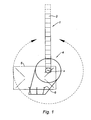
- the device for measuring the spreading distribution for spreader particle distributors comprises a bench 1 for fixed measurement of the quantities of granules distributed on the ground consisting of a row of collection bins 2 provided with measuring means 3 of the quantity of particles distributed, a support 4 for the particle distributor 5 positioned preferably in close proximity to the first collection tank 2 and arranged to rotate said distributor 5 about a selected axis of rotation and means for acquiring and storing at least the measurement data of the quantity of particles distributed and the angular positions of the dispenser relative to the measuring bench 1.
- the support 4 for the distributor 5 comprises a fixed first stator part mounted on a support or directly on the ground and a rotor part 4a whose rotation is generated by appropriate drive means. These drive means are arranged to rotate the distributor 5 according to an angular speed is fixed or programmable remotely, in successive steps or continuously.
- the rotor part 4a of the support 4 also has coupling and driving means 6 of the distributor 5 of the particles to be spread.
- These coupling means 6 are preferably installed on an interface intended to allow the adjustments in the longitudinal axis and the transverse axis of the position of the distributor, so as to coincide the axis of rotation X of the rotor part 4a. with that chosen to characterize the distributor 5, in FIG. 1 the axis of rotation x of a disk of the distributor 5.
- one of the first collection bins 2 of the measuring bench 1 is preferably provided at the vertical of the rotation point chosen for the test, here the center of the spreading disc.
- Each weighing means 3 connected to a collection bin may be connected to signal conditioning means 7 enabling the set of measuring means 3 arranged in the measuring bench 1 to be adjusted and paired.
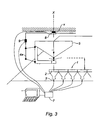
- other measuring means such as the means for measuring the angle 8 between the stator part of the support 4 and its rotor part 4a such as an optical encoder, the weighing means 9 of the distributor 5 such as a strain gauge are also connected to said signal conditioning means 7.
- the signal conditioning means then sends said processed signals to the recording and processing means.
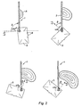
- the weighing data as well as the ⁇ angular values are recorded continuously during the test, and once the said test is completed, the raw data of the ground distribution can be processed spatially in order to establish the ground distribution sheet. .
- Figure 4a shows the ground distribution sheet obtained during a test according to the method of the invention. From this, it is possible to calculate by summation the quantities collected along the X axis (A), the transverse distribution obtained for the settings and the conditions of the test, represented in FIG. 4b by the curve B. According to that this test was carried out with one or more spreading discs, it is possible to edit the symmetrical transverse curve (C) to that measured for the case of a single disc, the curve D representing the total spreading for a single passage of the distributor or the transverse spreading result with recovery of the distributions of the different disks and finally the curve of the coefficients of variations E.
Landscapes
- Life Sciences & Earth Sciences (AREA)
- Soil Sciences (AREA)
- Environmental Sciences (AREA)
- Physics & Mathematics (AREA)
- General Physics & Mathematics (AREA)
- Fluid Mechanics (AREA)
- Catching Or Destruction (AREA)
- Sampling And Sample Adjustment (AREA)
Claims (10)
- Verfahren zur Messung der Streuverteilung für Partikelstreuer (b) mit einer Zentrifugalverteilung der Partikel über eine Scheibe, dadurch gekennzeichnet, dass der Partikelstreuer (5) mit Zentrifugalverteilung um eine gewählte Achse (X) drehbar zu einer fest stehenden Reihe oder Bank (1) mit Behältern für die Aufnahme (2) und Messung der Partikel angetrieben wird, wobei der Partikelstreuer (5) vorzugsweise in der Nähe der ersten Aufnahmebehälter angeordnet ist, in einem festgelegten Winkelbereich in jeder relativen Winkelposition (β) des Partikelstreuers zur Bank die über die gesamte Bank verteilten Partikelmengen gemessen werden, die Messdaten der Partikelmengen und die zugehörigen Winkelwerte ständig aufgezeichnet werden und ausgehend von den Messdaten und Winkelwerten die Verteilungslage auf dem Boden sowie die Querverteilungen beim Streuen berechnet werden.
- Verfahren nach Anspruch 1, dadurch gekennzeichnet, dass die gewählte Drehachse (X) die Drehachse einer Streuscheibe (x) ist.
- Verfahren nach Anspruch 1, dadurch gekennzeichnet, dass die gewählte Drehachse (X) der Mittelpunkt des Trägers zwischen zwei Streuscheiben desselben Partikelstreuers ist.
- Vorrichtung zur Messung der Streuverteilung für Partikelstreuer (5) mit einer Zentrifugalverteilung der Partikel über eine Scheibe, die eine feststehende Messbank (1) für die Messung der auf dem Boden verteilten Granulatmengen umfasst, die eine Reihe von Aufnahmebehältern (2), die mit Mitteln für die Messung der Menge der verteilten Partikel versehen ist, und eine Halterung (4) für den Partikelstreuer umfasst, die vorzugsweise in direkter Nähe der ersten Aufnahmebehälter angeordnet ist, dadurch gekennzeichnet, dass die Halterung so angeordnet ist, dass sie den Partikelstreuer um eine gewählte Drehachse (X) drehantreibt, und dass Mittel zur Erfassung (3) und Speicherung der Messdaten der Menge der verteilten Partikel und der Winkelpositionen (8) des Partikelstreuers zur Messbank vorgesehen sind.
- Vorrichtung nach Anspruch 4, dadurch gekennzeichnet, dass die Messbank (1) für die Messung der auf dem Boden verteilten Partikelmengen aus einem Behälterträger besteht, der in Form eines Traggestells ausgeführt ist, das so angeordnet ist, dass einer der ersten Behälter der Behälterreihe senkrecht zur Drehachse des Partikelstreuers angeordnet ist, wobei ein zweites Gestell, das von dem ersten Gestell unabhängig sein kann, die Mittel zur Messung der Menge der gestreuten Partikel aufnehmen kann.
- Vorrichtung nach Anspruch 5, dadurch gekennzeichnet, dass das erste Traggestell an seinen verschiedenen Seiten staubdichte Schutzvorrichtungen umfasst und von einer Vorrichtung durchlaufen wird, die dafür vorgesehen ist, die Umgebungsbedingungen wie Temperatur, Luftfeuchtigkeit usw. konstant zu halten.
- Vorrichtung nach einem der Ansprüche 5 und 6, dadurch gekennzeichnet, dass die Messmittel (3) vorzugsweise Wiegeeinheiten umfassen, die vorzugsweise einen Behälter für die zu wiegenden Partikel sowie einen Messwertgeber umfassen, der dafür vorgesehen ist, das Gewicht der in dem Behälter aufgenommenen Partikel zu messen.
- Vorrichtung nach einem der Ansprüche 4 bis 7, dadurch gekennzeichnet, dass die Halterung für den Streuer (4) einen ersten fest stehenden Statorteil, der an einer Halterung oder direkt am Boden befestigt ist, und einen Rotorteil (4a) umfasst, dessen Drehung von geeigneten Antriebsmitteln erzeugt wird, die so angeordnet sind, dass den Streuer mit einer festen oder fernprogrammierbaren Winkelgeschwingkeit schrittweise oder stufenlos drehbar antreiben.
- Vorrichtung nach Anspruch 8, dadurch gekennzeichnet, dass dei Rotorteil (4a) der Halterung (4) Rupplungs und Antriebsmittel (6) für den Partikelstreuer (b) aufweist, wobei die Kupplungsmittel (6) vorzugsweise an einer Schnittstelle angebracht sind, die dafür vorgesehen ist, Einstellungen der Position des Streuers in der Längsachse und in der Querachse zu ermöglichen, so dass die Drehachse (X) des Rotorteils (4a) mit der für die Auslegung des Streuers (5) gewählten Drehachse zusammentrifft.
- Vorrichtung nach einem der Ansprüche 4 bis 9, dadurch gekennzeichnet, dass die Mittel zur Erfassung (3) und Aufzeichnung der von den verschiedenen Messwertgebern gegebenen Werte, das heißt mindestens des Wiegewertes der Aufnahmebehälter und des relativen Winkelwertes (β) des Streuers zur Messbank, eine in Abhängigkeit von der gewünschten Genauigkeit und der Signalaufbereitungsqualität parametrierbare Messfrequenz aufweisen.
Applications Claiming Priority (2)
| Application Number | Priority Date | Filing Date | Title |
|---|---|---|---|
| FR0406698A FR2871885B1 (fr) | 2004-06-21 | 2004-06-21 | Procede de mesure de la repartition d'epandage pour epandeurs de particules a epandre |
| FR0406698 | 2004-06-21 |
Publications (2)
| Publication Number | Publication Date |
|---|---|
| EP1610112A1 EP1610112A1 (de) | 2005-12-28 |
| EP1610112B1 true EP1610112B1 (de) | 2007-08-22 |
Family
ID=34942429
Family Applications (1)
| Application Number | Title | Priority Date | Filing Date |
|---|---|---|---|
| EP20050291311 Active EP1610112B1 (de) | 2004-06-21 | 2005-06-20 | Messverfahren der Streuverteilung für Partikelstreuer |
Country Status (4)
| Country | Link |
|---|---|
| EP (1) | EP1610112B1 (de) |
| DE (1) | DE602005002083T2 (de) |
| DK (1) | DK1610112T3 (de) |
| FR (1) | FR2871885B1 (de) |
Cited By (5)
| Publication number | Priority date | Publication date | Assignee | Title |
|---|---|---|---|---|
| DE102009004114A1 (de) | 2009-01-09 | 2010-07-15 | Amazonen-Werke H. Dreyer Gmbh & Co. Kg | Verfahren zur Messung der Streuverteilung für Partikelstreuer und entsprechende Vorrichtung |
| EP2756745A1 (de) | 2013-01-17 | 2014-07-23 | MSO Messtechnik und Ortung GmbH | Verfahren zur Ermittlung der Verteilung eines Gutstroms mittels Mikrowellen, Sensoranordnung und entsprechende Vorrichtung |
| EP2883436A1 (de) | 2013-12-16 | 2015-06-17 | Amazonen-Werke H. Dreyer GmbH & Co. KG | Verfahren zur Ermittlung von Einstelldaten für Zentrifugalstreuer |
| WO2021078878A1 (en) | 2019-10-23 | 2021-04-29 | Carmeuse Research And Technology | Compacted calcium-based granules |
| WO2021078879A1 (en) | 2019-10-23 | 2021-04-29 | Carmeuse Research And Technology | Use of compacted calcium-based granules for soil conditioning in agriculture |
Families Citing this family (2)
| Publication number | Priority date | Publication date | Assignee | Title |
|---|---|---|---|---|
| DE102008052269B4 (de) * | 2008-10-18 | 2018-12-27 | Rauch Landmaschinenfabrik Gmbh | Einrichtung zum Überprüfen der Querverteilung an Zweischeibenstreuern |
| DE102016115764A1 (de) | 2016-08-25 | 2018-03-15 | Amazonen-Werke H. Dreyer Gmbh & Co. Kg | Messvorrichtung und Verfahren zur Anwendung einer derartigen Messvorrichtung |
Family Cites Families (4)
| Publication number | Priority date | Publication date | Assignee | Title |
|---|---|---|---|---|
| DD214988A1 (de) * | 1983-05-03 | 1984-10-31 | Guenter Jaenicke | Messeinrichtung zur ermittlung der verteilgenauigkeit, insbesondere von mineralduengerstreuern |
| DE3604449A1 (de) * | 1986-02-13 | 1987-08-20 | Amazonen Werke Dreyer H | Verfahren zur bestimmung der arbeitsbreite und der streudichte bei schleuderstreuern |
| SU1473734A1 (ru) * | 1987-03-23 | 1989-04-23 | Азово-Черноморский Институт Механизации Сельского Хозяйства | Прибор дл исследовани работы разбрасывателей удобрений |
| DE4105045A1 (de) * | 1991-01-18 | 1992-07-23 | Amazonen Werke Dreyer H | Verfahren zum einstellen der dosierorgane einer verteilmaschine |
-
2004
- 2004-06-21 FR FR0406698A patent/FR2871885B1/fr active Active
-
2005
- 2005-06-20 EP EP20050291311 patent/EP1610112B1/de active Active
- 2005-06-20 DE DE200560002083 patent/DE602005002083T2/de active Active
- 2005-06-20 DK DK05291311T patent/DK1610112T3/da active
Cited By (6)
| Publication number | Priority date | Publication date | Assignee | Title |
|---|---|---|---|---|
| DE102009004114A1 (de) | 2009-01-09 | 2010-07-15 | Amazonen-Werke H. Dreyer Gmbh & Co. Kg | Verfahren zur Messung der Streuverteilung für Partikelstreuer und entsprechende Vorrichtung |
| EP2756745A1 (de) | 2013-01-17 | 2014-07-23 | MSO Messtechnik und Ortung GmbH | Verfahren zur Ermittlung der Verteilung eines Gutstroms mittels Mikrowellen, Sensoranordnung und entsprechende Vorrichtung |
| EP2883436A1 (de) | 2013-12-16 | 2015-06-17 | Amazonen-Werke H. Dreyer GmbH & Co. KG | Verfahren zur Ermittlung von Einstelldaten für Zentrifugalstreuer |
| DE102013114110A1 (de) | 2013-12-16 | 2015-06-18 | Amazonen-Werke H. Dreyer Gmbh & Co. Kg | Verfahren zur Ermittlung von Einstelldaten für Zentrifugalstreuer |
| WO2021078878A1 (en) | 2019-10-23 | 2021-04-29 | Carmeuse Research And Technology | Compacted calcium-based granules |
| WO2021078879A1 (en) | 2019-10-23 | 2021-04-29 | Carmeuse Research And Technology | Use of compacted calcium-based granules for soil conditioning in agriculture |
Also Published As
| Publication number | Publication date |
|---|---|
| DK1610112T3 (da) | 2008-01-07 |
| FR2871885A1 (fr) | 2005-12-23 |
| DE602005002083T2 (de) | 2008-06-12 |
| DE602005002083D1 (de) | 2007-10-04 |
| EP1610112A1 (de) | 2005-12-28 |
| FR2871885B1 (fr) | 2006-08-11 |
Similar Documents
| Publication | Publication Date | Title |
|---|---|---|
| EP1610112B1 (de) | Messverfahren der Streuverteilung für Partikelstreuer | |
| EP0123602B1 (de) | Präzisionsmessvorrichtung und Verfahren für die Höhe der Schaufeln eines Rotors | |
| FR2764165A1 (fr) | Procede de reglage d'un epandeur centrifuge | |
| FR2502992A1 (fr) | Procede et dispositif pour le decriquage a la meule, controle de cylindres de laminoir | |
| US20240151523A1 (en) | Mobile turf instrument apparatus | |
| US9389214B2 (en) | Soil analysis apparatus, method, and system having a displaceable blade assembly and sensor | |
| US4356734A (en) | Soil sampling device | |
| FR2458353A1 (fr) | Procede et dispositif pour commander l'avance de la lame d'une scie a ruban horizontale dans la piece a scier | |
| EP0682857B1 (de) | Verfahren um die Streubreite für einen Granulatstreuer zu regeln | |
| EP3226671B1 (de) | System und verfahren zur automatischen anpassung eines landwirtschaftlichen anbaugeräts mit einem messenden lichtvorhang | |
| FR2595462A1 (fr) | Dispositif pour determiner l'angle de contact dans les roulements a billes | |
| EP0359664B1 (de) | Vorrichtung zum Messen einer Querabmessung eines im wesentlichen zylindrischen Objektes | |
| EP2986981A1 (de) | System zur feststellung des physiologischen zustands von pflanzen und entsprechendes verfahren | |
| EP0416976A1 (de) | Verfahren und Vorrichtung zur Messung der Konzentration von in der Luft suspendierten pulverartigen Materialien herangetragen durch Wind | |
| FR2653456A1 (fr) | Procede de reprofilage localise en continu d'un revetement ou surface, notamment d'une chaussure et machines pour sa mise en óoeuvre. | |
| EP2244085B1 (de) | Messung der Luminanz einer Fahrbahnoberfläche | |
| FR3113729A3 (fr) | Unité de contrôle polyvalente et déplaçable | |
| FR3090880A1 (fr) | Dispositif et procede de mesure d’au moins un parametre d’arrachage d’une plante | |
| FR2777817A1 (fr) | Procede et appareil de palpage de montures de lunettes, et machine de meulage correspondante | |
| CA2904024A1 (fr) | Dispositif de detourage de lentilles ophtalmiques | |
| FR2835604A1 (fr) | Procede et dispositif de mesure du volume d'un corps solide, tel que notamment une grume | |
| CA2410282A1 (fr) | Procede de deplacement automatique sur un terrain, d'un outil monte a l'extremite d'un bras articule | |
| FR2460475A1 (fr) | Installation et dispositif pour la determination in situ de l'evapotranspiration d'un couvert vegetal par la methode du bilan d'energie et la densite de flux de masse de gaz carbonique | |
| FR2960469A1 (fr) | Machine pour tailler des fonds de contenant | |
| FR2669046A1 (fr) | Dispositif de correction de nivellement adapte pour modifier le calage d'un capteur de nivellement equipant un engin de travaux publics destine a la confection ou la renovation de chaussees. |
Legal Events
| Date | Code | Title | Description |
|---|---|---|---|
| PUAI | Public reference made under article 153(3) epc to a published international application that has entered the european phase |
Free format text: ORIGINAL CODE: 0009012 |
|
| AK | Designated contracting states |
Kind code of ref document: A1 Designated state(s): AT BE BG CH CY CZ DE DK EE ES FI FR GB GR HU IE IS IT LI LT LU MC NL PL PT RO SE SI SK TR |
|
| AX | Request for extension of the european patent |
Extension state: AL BA HR LV MK YU |
|
| 17P | Request for examination filed |
Effective date: 20060623 |
|
| AKX | Designation fees paid |
Designated state(s): DE DK HU IT NL |
|
| GRAP | Despatch of communication of intention to grant a patent |
Free format text: ORIGINAL CODE: EPIDOSNIGR1 |
|
| GRAS | Grant fee paid |
Free format text: ORIGINAL CODE: EPIDOSNIGR3 |
|
| GRAA | (expected) grant |
Free format text: ORIGINAL CODE: 0009210 |
|
| AK | Designated contracting states |
Kind code of ref document: B1 Designated state(s): DE DK HU IT NL |
|
| REF | Corresponds to: |
Ref document number: 602005002083 Country of ref document: DE Date of ref document: 20071004 Kind code of ref document: P |
|
| REG | Reference to a national code |
Ref country code: DK Ref legal event code: T3 |
|
| REG | Reference to a national code |
Ref country code: HU Ref legal event code: AG4A Ref document number: E002454 Country of ref document: HU |
|
| PLBE | No opposition filed within time limit |
Free format text: ORIGINAL CODE: 0009261 |
|
| STAA | Information on the status of an ep patent application or granted ep patent |
Free format text: STATUS: NO OPPOSITION FILED WITHIN TIME LIMIT |
|
| 26N | No opposition filed |
Effective date: 20080526 |
|
| REG | Reference to a national code |
Ref country code: DE Ref legal event code: R082 Ref document number: 602005002083 Country of ref document: DE Representative=s name: WAGNER, DR. HERRGUTH PATENTANWAELTE, DE Ref country code: DE Ref legal event code: R081 Ref document number: 602005002083 Country of ref document: DE Owner name: INSTITUT NATIONAL DE RECHERCHE POUR L'AGRICULT, FR Free format text: FORMER OWNER: CENTRE NATIONAL DU MACHINISME AGRICOLE, DU GENIE RURAL, DES EAUX ET DES FORETS (CEMAGREF), ANTONY, FR |
|
| REG | Reference to a national code |
Ref country code: NL Ref legal event code: HC Owner name: INSTITUT NATIONAL DE RECHERCHE EN SCIENCES ET TECHNOLOGIES POUR L'ENVIRONNEMENT ET L'AGRICULTURE (IRSTEA); FR Free format text: DETAILS ASSIGNMENT: CHANGE OF OWNER(S), CHANGE OF OWNER(S) NAME; FORMER OWNER NAME: CENTRE NATIONAL DU MACHINISME AGRICOLE, DU GENIE RURAL, DES EAUX ET DES FORETS (CEMAGREF) Effective date: 20201210 Ref country code: NL Ref legal event code: PD Owner name: INSTITUT NATIONAL DE RECHERCHE POUR L'AGRICULTURE, L'ALIMENTATION ET L'ENVIRONNEMENT; FR Free format text: DETAILS ASSIGNMENT: CHANGE OF OWNER(S), MERGE; FORMER OWNER NAME: INSTITUT NATIONAL DE RECHERCHE EN SCIENCES ET TECHNOLOGIES POUR L'ENVIRONNEMENT ET L'AGRICULTURE (IRSTEA) Effective date: 20201210 |
|
| REG | Reference to a national code |
Ref country code: HU Ref legal event code: GB9C Owner name: INSTITUT NATIONAL DE RECHERCHE POUR L'AGRICULT, FR Free format text: FORMER OWNER(S): CENTRE NATIONAL DU MACHINE AGRICOLE, DU GENIE RURAL, DES EAUX ET DES FORETS (CEMAGREF), FR; CENTRE NATIONAL DU MACHINISME AGRICOLE, DU GENIE RURAL, DES EAUX ET DES FORETS (CEMAGREF), FR; CENTRE NATIONAL DU MACHINISME AGRICOLE, DU GENIE RURAL, DES EAUX ET DES FORETS (CEMAGREF), FR; INSTITUT NATIONAL DE RECHERCHE EN SCIENCES ET TECHNOLOGIES POUR L'ENVIRONNEMENT ET L'AGRICULTURE (IRSTEA), FR; INSTITUT NATIONAL DE RECHERCHE POUR L'AGRICULTURE, L'ALIMENTATION ET L'ENVIRIONMENT, FR; INSTITUT NATIONAL DE RECHERCHE POUR L'AGRICULTURE, L'ALIMENTATION ET L'ENVIRIONMENT, FR |
|
| P01 | Opt-out of the competence of the unified patent court (upc) registered |
Effective date: 20230530 |
|
| PGFP | Annual fee paid to national office [announced via postgrant information from national office to epo] |
Ref country code: NL Payment date: 20230622 Year of fee payment: 19 Ref country code: DK Payment date: 20230621 Year of fee payment: 19 Ref country code: DE Payment date: 20230620 Year of fee payment: 19 |
|
| PGFP | Annual fee paid to national office [announced via postgrant information from national office to epo] |
Ref country code: HU Payment date: 20230612 Year of fee payment: 19 |
|
| PGFP | Annual fee paid to national office [announced via postgrant information from national office to epo] |
Ref country code: IT Payment date: 20230630 Year of fee payment: 19 |