EP1609924A1 - Bâtiment préfabriqué, élément de plancher pour tel bâtiment préfabriqué et procédé de fabrication pour un élément de plancher - Google Patents
Bâtiment préfabriqué, élément de plancher pour tel bâtiment préfabriqué et procédé de fabrication pour un élément de plancher Download PDFInfo
- Publication number
- EP1609924A1 EP1609924A1 EP05076355A EP05076355A EP1609924A1 EP 1609924 A1 EP1609924 A1 EP 1609924A1 EP 05076355 A EP05076355 A EP 05076355A EP 05076355 A EP05076355 A EP 05076355A EP 1609924 A1 EP1609924 A1 EP 1609924A1
- Authority
- EP
- European Patent Office
- Prior art keywords
- layer
- floor
- prefabricated building
- tiles
- floor element
- Prior art date
- Legal status (The legal status is an assumption and is not a legal conclusion. Google has not performed a legal analysis and makes no representation as to the accuracy of the status listed.)
- Withdrawn
Links
Images


Classifications
-
- E—FIXED CONSTRUCTIONS
- E04—BUILDING
- E04B—GENERAL BUILDING CONSTRUCTIONS; WALLS, e.g. PARTITIONS; ROOFS; FLOORS; CEILINGS; INSULATION OR OTHER PROTECTION OF BUILDINGS
- E04B5/00—Floors; Floor construction with regard to insulation; Connections specially adapted therefor
- E04B5/43—Floor structures of extraordinary design; Features relating to the elastic stability; Floor structures specially designed for resting on columns only, e.g. mushroom floors
-
- E—FIXED CONSTRUCTIONS
- E04—BUILDING
- E04B—GENERAL BUILDING CONSTRUCTIONS; WALLS, e.g. PARTITIONS; ROOFS; FLOORS; CEILINGS; INSULATION OR OTHER PROTECTION OF BUILDINGS
- E04B5/00—Floors; Floor construction with regard to insulation; Connections specially adapted therefor
- E04B5/02—Load-carrying floor structures formed substantially of prefabricated units
- E04B5/04—Load-carrying floor structures formed substantially of prefabricated units with beams or slabs of concrete or other stone-like material, e.g. asbestos cement
-
- E—FIXED CONSTRUCTIONS
- E04—BUILDING
- E04B—GENERAL BUILDING CONSTRUCTIONS; WALLS, e.g. PARTITIONS; ROOFS; FLOORS; CEILINGS; INSULATION OR OTHER PROTECTION OF BUILDINGS
- E04B5/00—Floors; Floor construction with regard to insulation; Connections specially adapted therefor
- E04B5/02—Load-carrying floor structures formed substantially of prefabricated units
- E04B5/14—Load-carrying floor structures formed substantially of prefabricated units with beams or girders laid in two directions
-
- E—FIXED CONSTRUCTIONS
- E04—BUILDING
- E04B—GENERAL BUILDING CONSTRUCTIONS; WALLS, e.g. PARTITIONS; ROOFS; FLOORS; CEILINGS; INSULATION OR OTHER PROTECTION OF BUILDINGS
- E04B5/00—Floors; Floor construction with regard to insulation; Connections specially adapted therefor
- E04B5/16—Load-carrying floor structures wholly or partly cast or similarly formed in situ
- E04B5/17—Floor structures partly formed in situ
- E04B5/23—Floor structures partly formed in situ with stiffening ribs or other beam-like formations wholly or partly prefabricated
- E04B5/28—Cross-ribbed floors
-
- E—FIXED CONSTRUCTIONS
- E04—BUILDING
- E04B—GENERAL BUILDING CONSTRUCTIONS; WALLS, e.g. PARTITIONS; ROOFS; FLOORS; CEILINGS; INSULATION OR OTHER PROTECTION OF BUILDINGS
- E04B5/00—Floors; Floor construction with regard to insulation; Connections specially adapted therefor
- E04B5/48—Special adaptations of floors for incorporating ducts, e.g. for heating or ventilating
Definitions
- the invention relates to a prefabricated building, comprising a system of floors and columns, to which wall elements and roof elements are connected.
- Prefabricated buildings of this type are known. Usually, a prefabricated building is erecteded, after which a substantial amount of work still must be done for installing a heating system, a ventilation system and for installing an electricity supply and the like.
- the prefabricated building according to the invention substantially obviates this disadvantage and is according to an aspect of the invention characterised in that the floors are made up of floor elements of which at least one side is provided with coupling devices and of which corners rest on columns and that the building is provided with a central provision, from where heat, ventilation air, electricity and the like is distributed via at least part of the floor elements.
- a favourable embodiment is characterised in that the central provision is housed inside an at least substantially U-shaped or tubularly shaped building element.
- this U-shaped or tubularly shaped building element for example a staircase to a first floor may be accommodated. It is also possible to combine for example a toilet group or a bathroom group with the U-shaped or tubularly shaped building element, which results in a substantial reduction of the number of pipes that must be fitted into the prefabricated building.
- a favourable embodiment is according to a further aspect of the invention characterised in that floor elements each are built up like a sandwich, with a first layer comprising the reinforcement, a second layer, and a third layer which comprises tiles, mounted detachably or removably to the second layer in such a manner that between the second layer and the third layer air and wiring/piping, coming from the central provision can be distributed. Thanks to the tiles, the space between the second layer and the third layer remains accessible.
- the first layer is fabricated in such a way that there is no need to put on a finishing coat afterwards.
- the floor elements are characterised in that the second layer comprises a system of ribs, extending in a longitudinal and transverse direction, between which a system of recesses exists, while the intersections of ribs form points of support for the third layer.
- the second layer comprises a system of ribs, extending in a longitudinal and transverse direction, between which a system of recesses exists, while the intersections of ribs form points of support for the third layer.
- a further favourable embodiment is characterised in that at the intersections, the bottom side of the third layer and the bottom side of tiles are provided with notches, as a result of which the third layer will be positioned just above the ribs. In this way it is prevented that the third layer mutually disconnects the recesses, so that air and wiring/piping coming from the central provision may pass underneath the tiles.
- a further favourable embodiment is characterised in that the notches are made of a resilient material or that they are provided with a foot part made of a resilient material, as a result of which in fact a sprung floor is realised which will hardly conduct contact noise, produced for example when walking the third layer and the tiles, to the building as such.
- a further favourable embodiment is characterised in that the building is provided with skirting-constructions, provided with sealable openings, for letting pass air and/or wiring/piping conducted via the floor elements and/or the tiles if desired.
- the skirting-constructions consist of profiles, made of metal or plastic, which can be accommodated inside a recess in an inner wall.
- skirting-constructions consists of brackets and profiles, where the profiles are mounted detachably to the brackets and may be provided with skirting, sealable ventilation grilles and wall outlets.
- a further favourable embodiment is characterised in that a coupling device comprises at least two wired ends, installed on a side of a floor element and connected to a reinforcement of this floor element.
- a coupling between a floor element and another floor element can be realised then by coupling the threaded ends.
- the invention also relates to a floor element, to be used in a prefabricated building as described in the previous paragraphs.
- the invention also relates to a method for manufacturing a floor element.
- the inventive method according to which a floor element can be manufactured and in which provisions for heating, ventilation and the distribution of for example cables and coupling devices are present is characterised in that a first layer is cast into which a reinforcement is fit, onto which subsequently a second layer is cast in which a system of ribs extending in a longitudinal and a transverse direction and a system of recesses is made, as well as a system of coupling devices, after which a third layer is installed consisting of tiles, mounted detachably onto the second layer or consisting of a floor with cut-aways into which tiles can be mounted detachably.
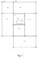
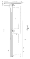
- Fig. 1 schematically shows a part of a possible embodiment of a prefabricated building according to the invention in top view, consisting of four rectangular floor elements 1a,1b,1c,1d and three square floor elements 2a,2b,2c of which the corner points are supported by columns 3a,3b,.. and which together form a base floor for the prefabricated building.
- Columns 3a,3b,.. are preferably anchored directly into the ground, but if preferred they may be placed onto a foundation plate or in a foundation tray or onto a prefabricated foundation.
- a prefabricated building set up in this way may be extended simply by adding columns and additional floor parts.
- the prefabricated building can also be extended without adding columns, by coupling additional floor parts to floor elements 1a,1b,1c,1d and/or floor elements 2a,2b,2c.
- Floor element 2b is here provided with a tubularly shaped building element 4, which comprises a central provision 5 consisting of a central heating, a ventilation unit, a mains supply and the like.
- Floor element 2b forms together with tubularly shaped building element 4 a backbone, from which the prefabricated building takes for an important part its strength.
- all floor elements 1a,1b,1c,1d, 2a,2b are directly or indirectly connected to central provision 5 via ducts, via which heated or if desired cooled air and/or wiring/piping can be passed to the different rooms.
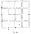
- Fig. 2A schematically shows a possible embodiment of a square floor element 2 in top view.
- Floor element 2 is made of concrete and consists of a sandwich of three layers. The lowest layer contains a reinforcement, not shown in this figure.
- the central layer contains a system of ribs 6, extending in a longitudinal and in a transverse direction, between which a system of recesses 7 is positioned. Crossings of ribs 6 form supports for corners of tiles 8, which tiles 8 form the third layer. Only the corners of tiles 8 rest onto the crossings of ribs 6, in such a way that some space is left open between tiles 8 and ribs 6, via which air, conditioned in central provision 5 as well as wiring/piping coming from central provision 5 may pass between tiles 8 and ribs 6.
- floor element 2 is provided with coupling devices 9, with which a floor element may be coupled to another floor element or with which a wall element, not shown here, may be coupled to a floor element.
- Coupling devices 9 are always placed in a rib, so that they can be coupled more easily to a reinforcement, present in the first layer.
- Floor element 2 shown here is square, but it may also be rectangular, for example as shown in Fig. 1.
- Fig. 2B schematically shows an alternative embodiment of a square floor element 2 in top view.
- Floor element 2 is made of concrete and consists of a sandwich of three layers. The lowest layer contains a reinforcement, not shown in this figure.
- the central layer contains a system of ribs 6, extending in a longitudinal and in a transverse direction, between which a system of recesses 7 is positioned. Crossings of ribs 6 form supports for a continuous third layer 8a, which now covers the entire surface of floor element 2, except for one or more openings into which tiles 8 can be placed.
- Third layer 8a rest onto the second layer only at the crossings of ribs 6, in such a way that some space is left open between third layer 8a and ribs 6, via which air, conditioned in central provision 5 as well as wiring/piping coming from central provision 5 may pass between third layer 8a with the tiles 8 included in it and ribs 6. More in general the space may also be used for letting pass wiring/piping.
- floor element 2 is provided with coupling devices 9, with which a floor element may be coupled to another floor element or with which a wall element, not shown here, may be coupled to a floor element. Coupling devices 9 are always placed in a rib, so that they can be coupled more easily to a reinforcement, present in the first layer.
- Floor element 2 shown here is square, but it may also be rectangular, for example as shown in Fig. 1.
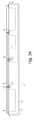
- Fig. 3A schematically shows a floor element 2 in side view, with first layer 10 which comprises reinforcement 11, with ribs 6 and recesses 7 in between which together form the second layer, with coupling devices 9 and with tiles 8 whose corners are provided with notches 12, bonded, pressed or cast to it, which rest on crossings of ribs 6.
- first layer 10 junction boxes may be included, to which lamps can be fitted in due course, as well as the necessary wiring/piping.
- First layer 10 and the second layer consisting of ribs 6 and recesses 7 can be produced in a single production process.
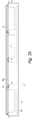
- Fig. 3B schematically shows an alternative floor element 2 in side view, with first layer 10 which contains a reinforcement 11, with ribs 6 and recesses 7 in between which together form the second layer, with coupling devices 9 and with third layer 8a, provided with notches 12, bonded, pressed or cast to it, which rest on crossings of ribs 6.
- third layer 8a tiles 8 can be included, of which the corners rest on crossings of ribs 6 or which rest in a further obvious manner in a frame, fit in third layer 8a.
- Fig. 4 schematically shows a floor element 2 and a wall element fitted to it in side view.
- Floor element 2 is provided with ribs 6, with recesses 7 and with coupling devices 9, of which the coupling devices 9 on one side are connected to a projecting anchorplate 13, onto which in this embodiment an insulation layer 14 and an outer wall 15 rests.
- An inner wall 16 rests directly onto floor element 2 and is provided with small grids 17, in such a way that air, supplied via a space between third layer 8a and floor element 2 will enter room 18 via the grids 17 and in this way will realise a controlled ventilation inside the building, while moreover wiring/piping can be passed in this way.
- An important additional advantage is that the air prevents a cold spot coming into being near projecting anchorplate 13.
- Fig. 5A shows more in detail a number of tiles 8 in top view.
- a tile On each corner a tile is provided with a recess 19, in such a way that between four tiles fit together, a bolt may pass, with which a corner of all four tiles is attached to a floor element, which is for that purpose provided with an embedded screwed sleeve on that place.
- the tiles are moreover provided with a wider recess 20, in such a way that a head of the bolt will fit into the joint recesses of four tiles and a substantially continuous surface is obtained.
- the tiles may be made of a heat conducting material, which means that the entire floor may be heated or cooled and/or they may be made of an attractive material, which means that an additional floor covering will be superfluous.
- a third layer 8a in which individual tiles 8 are embedded may also be provided with recesses 19,20 in an obvious manner, which means that individual tiles 8 can be fixed in the previously described manner.
- Fig. 5B shows a possible embodiment of these tiles 8 in side view. Visible are the notches 12, bonded, pressed or cast to the corners, of which a bottom side is preferably provided with a resilient layer 21, for example made of rubber, which prevents contact noise from being passed to floor element 2. If moreover the heads of the bolts with which the tiles are attached are provided with a spacer made of a resilient material, then a sprung floor is realised in this manner, for which contact noise is virtually not an object any more.
- a tile 8 Moreover the opening between floor part 2 and the bottom side of a tile 8 is visible, via which an air current may pass freely and which offers room for cables and wiring/piping, as well as a tile 8 in which by way of illustration a strip 22 is placed between two notches 12, for example made of rubber, with which the air current may be closed off. In this way, a pattern may be fit in, with which the airflow underneath the tiles 8 can be guided in a simple manner.
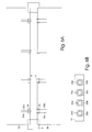
- Fig. 6A schematically shows a coupling of two floor elements 2a,2b, with coupling devices 9 consisting of threaded ends.
- Floor element 2a is provided with pairs of threaded ends 23a,23b which can be accessed with the aid of a recess 24 in floor element 2a.
- Floor element 2b is also provided with pairs of threaded ends 25a,25b which can be accessed with the aid of a recess 26 in floor element 2b.
- the threaded ends 23a,23b and 25a,25b may be connected to the reinforcements of floor element 2a respectively floor element 2b.
- floor element 2a and floor element 2b are shown somewhat separated for the sake of clarity.
- the recesses 24,26 form one single recess in which the ends of the threaded ends 25a,23a,23b,25b parallel each other.
- a comb shaped object made of steel can be placed, after which the threaded ends can be fastened with the aid of nuts.
- Fig. 6B shows more in detail a coupling in side view, with a comb 27 made of steel and the threaded ends 25a,23a,23b,25b which are fastened with the aid of nuts 28a,28b,28c,28d.
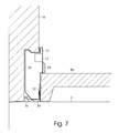
- Fig. 7 shows more in detail a possible embodiment of a skirting-construction, consisting of a system of brackets 29 which are at floor level pushed into a constructional recess in inner wall 16 and which are kept in place with the aid of springs 30, and of profiles 31 which can be slid into brackets 29 after third layer 8a has been put in place, with springs 32 keeping them in place.
- Profiles 31 may be delivered in standard lengths and may be provided with skirting 33 and grids 17 and/or sockets which have already been wired.
- Brackets 29 and profiles 31 are preferably made of plastic or metal. Brackets 29 may moreover be used for keeping cables 34 in place, which are laid in the constructional recess.
- wall elements and roof elements may be put in place in a manner well known in the art.
- the wall elements are placed such that they can be bodily removed if desired and reused, for example for an enlargement of another prefabricated building.
- the floor elements can be coupled to existing floor elements with the aid of the coupling devices 9, without the need of adding columns or another form of foundation.
Applications Claiming Priority (6)
| Application Number | Priority Date | Filing Date | Title |
|---|---|---|---|
| NL1026494A NL1026494C1 (nl) | 2004-06-24 | 2004-06-24 | Geprefabriceerd gebouw, vloerelement voor een dergelijk gebouw en werkwijze voor het vervaardigen van een vloerelement. |
| NL1026494 | 2004-06-24 | ||
| NL1027989 | 2005-01-10 | ||
| NL1027989A NL1027989C1 (nl) | 2004-06-24 | 2005-01-10 | Geprefabriceerd gebouw, vloerelement voor een dergelijk gebouw en werkwijze voor het vervaardigen van een vloerelement. |
| NL1028516 | 2005-03-10 | ||
| NL1028516A NL1028516C1 (nl) | 2004-06-24 | 2005-03-10 | Geprefabriceerd gebouw, vloerelement voor een dergelijk gebouw en werkwijze voor het vervaardigen van een vloerelement. |
Publications (1)
| Publication Number | Publication Date |
|---|---|
| EP1609924A1 true EP1609924A1 (fr) | 2005-12-28 |
Family
ID=35057137
Family Applications (1)
| Application Number | Title | Priority Date | Filing Date |
|---|---|---|---|
| EP05076355A Withdrawn EP1609924A1 (fr) | 2004-06-24 | 2005-06-10 | Bâtiment préfabriqué, élément de plancher pour tel bâtiment préfabriqué et procédé de fabrication pour un élément de plancher |
Country Status (2)
| Country | Link |
|---|---|
| EP (1) | EP1609924A1 (fr) |
| NL (1) | NL1028516C1 (fr) |
Cited By (5)
| Publication number | Priority date | Publication date | Assignee | Title |
|---|---|---|---|---|
| WO2007137318A1 (fr) | 2006-05-30 | 2007-12-06 | Technische Universität Wien | Construction PORTEUSE en bÉton plane et procÉdÉ de rÉalisation de celle-ci |
| NL2004863C2 (en) * | 2010-06-09 | 2011-12-13 | Infra & B V | Building or part thereof, prefab floor part and method for forming a building or a floor part. |
| WO2011155842A1 (fr) * | 2010-06-09 | 2011-12-15 | Infra+ B.V. | Plancher, comprenant des éléments préfabriqués avec des poches et des moyens d'accès facile auxdites poches et à partir de celles-ci |
| EP3061881A1 (fr) * | 2015-02-24 | 2016-08-31 | Spurgin Leonhart | Balcon à nervure prefabriqué |
| WO2018149549A1 (fr) | 2017-02-20 | 2018-08-23 | Bernd Heidenreich | Module de structure porteuse plane |
Citations (5)
| Publication number | Priority date | Publication date | Assignee | Title |
|---|---|---|---|---|
| GB1061783A (en) * | 1962-08-17 | 1967-03-15 | Oscar Singer | Improvements to building structures and the joint members thereof |
| US3442058A (en) * | 1968-05-31 | 1969-05-06 | Eng Collaborative Ltd The | Concrete floor construction with duct-forming voids |
| DE2147039A1 (de) * | 1971-09-21 | 1973-03-29 | Reinhard Dipl Ing Both | Beton-fertigteile fuer ein estrichunterflur-system |
| DE2324224A1 (de) * | 1973-05-14 | 1974-12-05 | Wilhelm Johannes Di Silberkuhl | Hochhaus |
| FR2282510A1 (fr) * | 1974-08-23 | 1976-03-19 | Babu Jean Pierre | Structure multi-fonctionnelle de separation entre niveaux d'un batiment |
-
2005
- 2005-03-10 NL NL1028516A patent/NL1028516C1/nl not_active IP Right Cessation
- 2005-06-10 EP EP05076355A patent/EP1609924A1/fr not_active Withdrawn
Patent Citations (5)
| Publication number | Priority date | Publication date | Assignee | Title |
|---|---|---|---|---|
| GB1061783A (en) * | 1962-08-17 | 1967-03-15 | Oscar Singer | Improvements to building structures and the joint members thereof |
| US3442058A (en) * | 1968-05-31 | 1969-05-06 | Eng Collaborative Ltd The | Concrete floor construction with duct-forming voids |
| DE2147039A1 (de) * | 1971-09-21 | 1973-03-29 | Reinhard Dipl Ing Both | Beton-fertigteile fuer ein estrichunterflur-system |
| DE2324224A1 (de) * | 1973-05-14 | 1974-12-05 | Wilhelm Johannes Di Silberkuhl | Hochhaus |
| FR2282510A1 (fr) * | 1974-08-23 | 1976-03-19 | Babu Jean Pierre | Structure multi-fonctionnelle de separation entre niveaux d'un batiment |
Cited By (10)
| Publication number | Priority date | Publication date | Assignee | Title |
|---|---|---|---|---|
| WO2007137318A1 (fr) | 2006-05-30 | 2007-12-06 | Technische Universität Wien | Construction PORTEUSE en bÉton plane et procÉdÉ de rÉalisation de celle-ci |
| EP2024580A1 (fr) * | 2006-05-30 | 2009-02-18 | Technische Universität Wien | CONSTRUCTION PORTEUSE ENbÉTON PLANE ET PROCÉdÉ DE rÉALISATION DE CELLE-Ci |
| NL2004863C2 (en) * | 2010-06-09 | 2011-12-13 | Infra & B V | Building or part thereof, prefab floor part and method for forming a building or a floor part. |
| WO2011155840A1 (fr) * | 2010-06-09 | 2011-12-15 | Infra+ B.V. | Bâtiment ou élément de bâtiment, élément de plancher préfabriqué et procédé de formation d'un bâtiment ou d'un élément de plancher |
| WO2011155842A1 (fr) * | 2010-06-09 | 2011-12-15 | Infra+ B.V. | Plancher, comprenant des éléments préfabriqués avec des poches et des moyens d'accès facile auxdites poches et à partir de celles-ci |
| EP3061881A1 (fr) * | 2015-02-24 | 2016-08-31 | Spurgin Leonhart | Balcon à nervure prefabriqué |
| WO2018149549A1 (fr) | 2017-02-20 | 2018-08-23 | Bernd Heidenreich | Module de structure porteuse plane |
| DE102017001551A1 (de) | 2017-02-20 | 2018-08-23 | Bernd Heidenreich | Flächentragwerksmodul |
| CN110312839A (zh) * | 2017-02-20 | 2019-10-08 | 伯恩·海登里奇 | 面型承载机构模块 |
| US11339562B2 (en) | 2017-02-20 | 2022-05-24 | Bernd Heidenreich | Area-covering structure module |
Also Published As
| Publication number | Publication date |
|---|---|
| NL1028516C1 (nl) | 2005-12-28 |
Similar Documents
| Publication | Publication Date | Title |
|---|---|---|
| CA2733310C (fr) | Module de construction en materiau composite pourvu d'un radiateur a masse thermique | |
| CA2577139C (fr) | Chambre et structure modulaires | |
| US8839568B2 (en) | Multi-Dwelling Structure | |
| US20110120049A1 (en) | Prefabricated Building Components and Assembly Equipment | |
| EP2240652A1 (fr) | Éléments de constuction préfabriqués et équipements d'assemblage | |
| US20120017525A1 (en) | Interlocking Building Panel | |
| EP1609924A1 (fr) | Bâtiment préfabriqué, élément de plancher pour tel bâtiment préfabriqué et procédé de fabrication pour un élément de plancher | |
| US20110047898A1 (en) | Building components and the buildings constructed therewith | |
| JP2002536615A (ja) | 床構造における空洞内の熱分布用配置構成 | |
| US6164026A (en) | Raised access floor | |
| EP2792803B1 (fr) | Procédé de construction d'un bâtiment | |
| KR200425116Y1 (ko) | 조립식 컨테이너 교실 | |
| US9453647B2 (en) | Floor with radiant heat and method of construction | |
| KR101703306B1 (ko) | 층간 소음 저감을 위한 바닥구조 및 이의 시공방법 | |
| KR100467536B1 (ko) | 방열판 및 유리온돌판을 구비한 악세스 플로어형 바닥구조및 그 시공방법 | |
| US9970200B1 (en) | Raised adjustable insulated flooring system | |
| WO2006016120A1 (fr) | Kit de construction d’immeuble avec panneaux de murs élevés détages | |
| WO1998023824A1 (fr) | Systeme de plancher ouvert permettant d'en assurer l'entretien | |
| NL1027989C1 (nl) | Geprefabriceerd gebouw, vloerelement voor een dergelijk gebouw en werkwijze voor het vervaardigen van een vloerelement. | |
| CA3000263C (fr) | Systeme de plancher isole ajustable sureleve | |
| US20230399845A1 (en) | A floor cassette | |
| JP3657458B2 (ja) | 床組工法 | |
| NL1026494C1 (nl) | Geprefabriceerd gebouw, vloerelement voor een dergelijk gebouw en werkwijze voor het vervaardigen van een vloerelement. | |
| RU22641U1 (ru) | Мобильное здание | |
| EP3423646B1 (fr) | Plancher de base d'un bâtiment et procédé de construction d'une base d'un bâtiment |
Legal Events
| Date | Code | Title | Description |
|---|---|---|---|
| PUAI | Public reference made under article 153(3) epc to a published international application that has entered the european phase |
Free format text: ORIGINAL CODE: 0009012 |
|
| AK | Designated contracting states |
Kind code of ref document: A1 Designated state(s): AT BE BG CH CY CZ DE DK EE ES FI FR GB GR HU IE IS IT LI LT LU MC NL PL PT RO SE SI SK TR |
|
| AX | Request for extension of the european patent |
Extension state: AL BA HR LV MK YU |
|
| 17P | Request for examination filed |
Effective date: 20060612 |
|
| AKX | Designation fees paid |
Designated state(s): AT BE BG CH CY CZ DE DK EE ES FI FR GB GR HU IE IS IT LI LT LU MC NL PL PT RO SE SI SK TR |
|
| D17P | Request for examination filed (deleted) | ||
| REG | Reference to a national code |
Ref country code: DE Ref legal event code: 8566 |
|
| STAA | Information on the status of an ep patent application or granted ep patent |
Free format text: STATUS: THE APPLICATION IS DEEMED TO BE WITHDRAWN |
|
| 18D | Application deemed to be withdrawn |
Effective date: 20060629 |