EP1609703A2 - Poutre transversale - Google Patents
Poutre transversale Download PDFInfo
- Publication number
- EP1609703A2 EP1609703A2 EP05013399A EP05013399A EP1609703A2 EP 1609703 A2 EP1609703 A2 EP 1609703A2 EP 05013399 A EP05013399 A EP 05013399A EP 05013399 A EP05013399 A EP 05013399A EP 1609703 A2 EP1609703 A2 EP 1609703A2
- Authority
- EP
- European Patent Office
- Prior art keywords
- cross member
- holder
- member according
- component
- profile
- Prior art date
- Legal status (The legal status is an assumption and is not a legal conclusion. Google has not performed a legal analysis and makes no representation as to the accuracy of the status listed.)
- Granted
Links
Images


Classifications
-
- B—PERFORMING OPERATIONS; TRANSPORTING
- B60—VEHICLES IN GENERAL
- B60R—VEHICLES, VEHICLE FITTINGS, OR VEHICLE PARTS, NOT OTHERWISE PROVIDED FOR
- B60R21/00—Arrangements or fittings on vehicles for protecting or preventing injuries to occupants or pedestrians in case of accidents or other traffic risks
- B60R21/02—Occupant safety arrangements or fittings, e.g. crash pads
- B60R21/04—Padded linings for the vehicle interior ; Energy absorbing structures associated with padded or non-padded linings
- B60R21/045—Padded linings for the vehicle interior ; Energy absorbing structures associated with padded or non-padded linings associated with the instrument panel or dashboard
-
- B—PERFORMING OPERATIONS; TRANSPORTING
- B62—LAND VEHICLES FOR TRAVELLING OTHERWISE THAN ON RAILS
- B62D—MOTOR VEHICLES; TRAILERS
- B62D25/00—Superstructure or monocoque structure sub-units; Parts or details thereof not otherwise provided for
- B62D25/08—Front or rear portions
- B62D25/14—Dashboards as superstructure sub-units
- B62D25/145—Dashboards as superstructure sub-units having a crossbeam incorporated therein
-
- B—PERFORMING OPERATIONS; TRANSPORTING
- B62—LAND VEHICLES FOR TRAVELLING OTHERWISE THAN ON RAILS
- B62D—MOTOR VEHICLES; TRAILERS
- B62D29/00—Superstructures, understructures, or sub-units thereof, characterised by the material thereof
- B62D29/001—Superstructures, understructures, or sub-units thereof, characterised by the material thereof characterised by combining metal and synthetic material
- B62D29/004—Superstructures, understructures, or sub-units thereof, characterised by the material thereof characterised by combining metal and synthetic material the metal being over-moulded by the synthetic material, e.g. in a mould
-
- B—PERFORMING OPERATIONS; TRANSPORTING
- B60—VEHICLES IN GENERAL
- B60R—VEHICLES, VEHICLE FITTINGS, OR VEHICLE PARTS, NOT OTHERWISE PROVIDED FOR
- B60R21/00—Arrangements or fittings on vehicles for protecting or preventing injuries to occupants or pedestrians in case of accidents or other traffic risks
- B60R21/02—Occupant safety arrangements or fittings, e.g. crash pads
- B60R21/16—Inflatable occupant restraints or confinements designed to inflate upon impact or impending impact, e.g. air bags
- B60R21/20—Arrangements for storing inflatable members in their non-use or deflated condition; Arrangement or mounting of air bag modules or components
- B60R21/205—Arrangements for storing inflatable members in their non-use or deflated condition; Arrangement or mounting of air bag modules or components in dashboards
Definitions
- the invention relates to a cross member according to the preamble of the claim 1.
- Crossbeams are usually made of steel, aluminum or magnesium, wherein for attachment of components to be attached thereto, such as the instrument panel, the steering column or an airbag to which Cross member holders are welded or screwed, to which the corresponding components are screwed.
- components to be attached thereto such as the instrument panel, the steering column or an airbag to which Cross member holders are welded or screwed, to which the corresponding components are screwed.
- the assembly relatively expensive.
- a cross member is provided, with one on the cross member provided holder, with the help of the cross member, a component attachable is, wherein the holder is integrally formed with the cross member.
- the cross member is preferably a hybrid component, in particular with a or two Metallkörpem, which are preferably cup-shaped.
- the Metal bodies are at least partially inside and / or outside of Plastic surrounded, wherein the plastic also a honeycomb structure and / or channels, for example for air guidance, may have.
- the holder is molded by a molded on a base body Area made of plastic or one in a molded area formed injected element, which also completely or partially from Plastic can be surrounded.
- the production can be done in one operation done with the production of the cross member.
- the holder comprises a guide for the help with the cross member to be attached element with a degree of freedom in one direction.
- Degree of freedom preferably runs in the longitudinal direction of the cross member, however Other orientations are possible. Especially in case of Longitudinal extent of the degree of freedom can be delayed due to aging and shrinkage are minimized. Furthermore, targeted loose and fixed bearings are on Holder possible, so that an optimized attachment of a component to the cross member is possible.
- the holder is by a longitudinally extending undercut or a prominent profile formed.
- the undercut is preferred a T-groove, a V-groove or a dovetail groove, the above profile is preferably a T, L, Z, U profile, a dovetail profile and / or a cylindrical or partially cylindrical profile. Further Profile shapes are possible.
- the holder is a device for fixing or a part thereof intended.
- This device may be through aligned openings be formed, in which a pin is inserted.
- At least one stop is provided, which part of a device for fixation.
- the stop in the case of a longitudinal guide trained holder may be provided at one end of the holder.
- the final fixation may be on the other side or at another Place done.
- the holder preferably has a resilient, hook-shaped area on, which cooperates with another hook-shaped area, which is provided on the element to be fastened to the holder. This allows a quick installation and fixation by means of snapping.
- Such a cross member is preferably arranged in the cockpit of a motor vehicle, with the help of the holder attaching the instrument panel is provided.
- the holder preferably extends in the longitudinal or transverse direction of the crossbeam. This allows a simple and large-scale attachment the instrument panel on the cross member.
- an impact protection device is provided which, if necessary, especially in the case of a head impact in a crash, a displacement of the component, in particular the instrument panel, on the Cross member allows to, so that the occupant best possible from injury is protected.
- a path-dependent increase in the displacement is preferred given the force required, with the force in relation to Path is preferably at least linear, but preferably faster, i. for example exponential, increases.
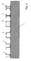
- the holder 5 extends in the present case in the transverse direction of the cross member 1.
- the open groove end is widened designed so that easy insertion and centering without Jamming is possible.
- the other end of the groove is closed with a stop, which is designed such that it the end position of the instrument panel 6 defined so that the instrument panel 6 during assembly simply pushed in until it stops.
- the fixation of the instrument panel 6 in the cross member 1 by means of a pin can However, in any other way, for example by a Clamping screw, a bolt or possibly also by a clip connection, wherein a part, for example an opening, on the cross member. 1 and a part, for example a spring arm, which engages in the opening the instrument panel 6 is formed.
- a T-shaped Profile trained is on the cross member in one piece with the plastic structure a T-shaped Profile trained, the in an appropriately trained groove on a component to be attached to the cross member, for example an instrument panel, is introduced. If the component is pushed from the side, thus, a fixation by means of a pin, which takes place in an opening in the component, which with exact positioning with a second opening in the T-shaped Profile is aligned, is introduced.
- a T-shaped profile formed on the cross member is by a double T-shaped metal insert, which injected, reinforced, so that larger forces are absorbed can.
- the function corresponds to that of the second embodiment.
- the metal insert I-shaped, so that in the transverse region no metal reinforcement is provided.
- This embodiment allows a rigid design in one direction and in -Z direction (towards the cross member too) and a softer configuration in the + Z direction (away from the cross member).
- an area with an L-shaped on the cross member protruding profile integrally formed can be about a fully formed by a part of the plastic structure area the cross member act.
- the L-shaped protruding profile is a formed on its one side in the plastic structure injected metal profile, wherein the metal profile on the injected side, for example, L- or T-shaped may be formed.
- the cross member 1 is a Z-shaped Profile formed integrally with the plastic structure 3, as shown in FIG. 3 at the far left.
- the profile is on Introducing thinner and the laterally projecting end shorter educated.
- the height can decrease in the mounting direction.
- the to be attached to the cross member 1 component has an L-shaped groove whose Dimensions are matched with those of the Z-shaped profile.
- a U-shaped profile is provided, the profile is arranged on the cross member 1 so that it is open and laterally projecting Has edges.
- the component to be attached to the cross member 1 is has an undercut groove. This embodiment corresponds from its function forth in the embodiment shown in Fig. 3 rightmost according to the two opposite C-shaped profiles are provided.
- Fig. 3 As a third from the left two mirror-inverted Z-shaped profiles are provided, their leg remote from the cross member 1 to point to each other. Between the two Z-shaped profiles a T-shaped profile is introduced, which is provided on the component to be attached to the cross member 1. In terms of its function, this embodiment corresponds to the right thereof embodiment shown in Fig. 3, which two C-shaped Has profiles that face each other.
- the cross member 1 profile double-T-shaped educated.
- the component to be mounted on the cross member 1 has a T-slot on, which corresponds approximately to the dimensions of the profile on the cross member 1 in their dimensions.
- Embodiments are reinforcing elements in the profiles provided corresponding to the thick solid lines in Fig. 3rd run and at least partially surrounded by the plastic structure 3 are or only made of plastic.
- a pocket serving as a holder is formed in the plastic structure, in which a counterpart of the cross member to be fastened component is inserted.
- the fixation can by means of a clip connection, a Stick, by gluing or otherwise done.
- the pocket is reinforced, with a reinforcing insert injected into the plastic or the metallic part of the cross member is designed accordingly.
- a bag instead of a bag also be designed a tab.
- the cross member base structure can also be the projecting collar as a guide for a to be attached to the cross member Serve component
- the federal government in conjunction with other elements directly serves as a holder, so that no later to be attached to the cross member Holder, as in the prior art, must be used.
- the component to be attached has a groove, in which the federal government at the assembly is introduced.
- the attachment can be done in a known manner.
- the collar may be chamfered and / or the groove extended at an introduction to the federal above or at a Introduction from the side to be laterally expanded.
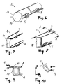
- FIG. 6 An example of a two shells 10 existing cross member is in Fig. 6 shown.
- the holder 5 are in the present embodiment in cross section of the shape of a hexagon or a circle in the shells 10 executed, with any configurations, in particular further polygon shapes possible are.
- FIG Fig. 7 is a cross member of two substantially U-shaped shells 10 with different lengths of thighs sketched.
- a holder 5 is in shape a pocket in the upper region of the first, smaller cross-section shell 10, and in the lower part of the second larger cross-section shell 10, formed.
- the two holders can only in one of the be formed two shells 10.
- the cross member 1 exists from two Z-shaped shells 10.
- a section in the region of a holder 5 through the cross member 1 is shown in Fig. 9.
- a Holder 5 is formed
- FIG. 10 schematically sketched.
- a cross member 1 is with the surfaces of its shells 10 inclined to the Z and X direction arranged.
- the mounting direction of a to be grown part, indicated by an arrow, runs in the X direction.
- the holder 5 is substantially in the X direction oriented, whereby this with its receiving surfaces substantially inclined to the cross member axis or to the shells 10 of the cross member forming surfaces is arranged.
- a corresponding projection to the federal government, which serves as a holder, can also any other outer surface of the cross member through the plastic structure be formed, reinforced or unreinforced, depending on the expected Burden.
- the dimensions of the profiles of the holder and the counterparts on this to be mounted component can be formed as needed, so that certain desired properties can be achieved, in particular a certain game in a certain direction or a play-free and thus stiff connection in a certain direction.
- This can be special be specifically used to increase the crash safety, so that, for example the connection of the instrument panel in + Z-direction, that is away from the cross member, stiff, so no bending can take place, such as required for airbag deployment, and in -Z direction, the means on the cross member, formed deformable in a certain range can be, so some protection in case of a head impact
- the release in -Z direction can be force-dependent, so that a Klappem can be avoided in normal operation. This is for example through a system with friction in one area of the profile possible.
- Fig. 4 shows a part of a cross member 1 with integrally formed holder 5 and a Part of a component attached thereto 7.
- the holder 5 includes here an impact protection device 8, which ensures that in the case of Crashes, especially in the event of a head impact of an occupant of the vehicle, a certain, defined deformation, in this case a shift of the component 7 in the arrow direction by a distance s, is possible, so that the Injury risk can be significantly reduced.
- the holder 5 has an open-topped U-shaped profile, wherein on the inner sides of the legs for receiving a widened area the fastening region of the component 7 groove-shaped receptacles provided are, which are bevelled upwards, ie to the component 7, so that in Crash, a continuous deformation of the holder 5 and / or the mounting area of the component 7 and thus a shift down in the holder 5 is possible.
- the lower portion of the holder 5 has a Width, which about the distance of the groove-shaped receptacles from each other in the groove bottom or the width of the component 7 in the widest part of the mounting area equivalent.
- the displacement of the component 7 relative to the holder 5 is characterized by a ensures certain elasticity and / or plastic deformability and by a bearing of a surface 9 of the component 7 at a contact area limited by the holder.
- both the holder 5 as Also, the component 7 preferably elastic, possibly also plastically deformed become.
- the holder 5 according to the following embodiment shown in Fig. 5 also has an impact protection device 8, which has a displaceability by a load-dependent distance s of the component 7 allows the cross member 1 to if necessary.
- the design of the attachment area of the component 7 corresponds to that of the previous embodiment.
- the function is essentially the same as in the one described above Embodiment, however, is exclusively an elastic Deformation of the holder 5, which widens.
- the slope, which in their function of o. g. Bevel corresponds, but this is clear flatter, allowing a continuous increase in the power depending the deformation path given to the stop of the contact surfaces is.
- the displacement of the component 7 relative to the holder 5 becomes a Installation of a surface 9 of the component 7 at a contact area of the holder limited.
Applications Claiming Priority (2)
| Application Number | Priority Date | Filing Date | Title |
|---|---|---|---|
| DE102004030689 | 2004-06-24 | ||
| DE102004030689A DE102004030689A1 (de) | 2004-06-24 | 2004-06-24 | Querträger |
Publications (3)
| Publication Number | Publication Date |
|---|---|
| EP1609703A2 true EP1609703A2 (fr) | 2005-12-28 |
| EP1609703A3 EP1609703A3 (fr) | 2006-10-04 |
| EP1609703B1 EP1609703B1 (fr) | 2008-12-17 |
Family
ID=34937591
Family Applications (1)
| Application Number | Title | Priority Date | Filing Date |
|---|---|---|---|
| EP05013399A Not-in-force EP1609703B1 (fr) | 2004-06-24 | 2005-06-22 | Poutre transversale |
Country Status (3)
| Country | Link |
|---|---|
| EP (1) | EP1609703B1 (fr) |
| AT (1) | ATE417778T1 (fr) |
| DE (2) | DE102004030689A1 (fr) |
Cited By (4)
| Publication number | Priority date | Publication date | Assignee | Title |
|---|---|---|---|---|
| WO2022079636A1 (fr) * | 2020-10-13 | 2022-04-21 | Polestar Performance Ab | Ensemble poutre de wagon transversal avec joint conique |
| US11318993B1 (en) | 2020-10-13 | 2022-05-03 | Polestar Performance Ab | Modular cross car beam assembly |
| EP4122803A1 (fr) * | 2020-11-11 | 2023-01-25 | Volkswagen AG | Support du tableau de bord pour un véhicule automobile |
| US11572105B2 (en) | 2020-10-13 | 2023-02-07 | Polestar Performance Ab | Cross car beam assembly with integral safety unit |
Families Citing this family (2)
| Publication number | Priority date | Publication date | Assignee | Title |
|---|---|---|---|---|
| DE102012007973A1 (de) | 2012-04-20 | 2013-10-24 | GM Global Technology Operations LLC (n. d. Gesetzen des Staates Delaware) | Vorrichtung zum Befestigen einer komprimierbarenFlächenstruktur an einem Karosserieteil eines Fahrzeuges |
| DE102017200113B4 (de) | 2017-01-05 | 2020-07-09 | Volkswagen Aktiengesellschaft | Stoßfängerquerträger für ein Kraftfahrzeug sowie Kraftfahrzeug mit einem solchen Stoßfängerquerträger |
Family Cites Families (11)
| Publication number | Priority date | Publication date | Assignee | Title |
|---|---|---|---|---|
| AT22852B (de) * | 1902-12-04 | 1906-01-25 | Arthur Edelmann | Verfahren zur Herstellung von Elektroden für elektrische Bogenlampen. |
| DE19626441B4 (de) * | 1996-06-20 | 2004-03-25 | Sommer-Allibert-Lignotock Gmbh | Cockpit für Kraftfahrzeuge |
| US5934733A (en) * | 1997-12-19 | 1999-08-10 | General Motors Corporation | Extruded instrument panel structure |
| DE19854076C1 (de) * | 1998-11-24 | 2000-04-13 | Daimler Chrysler Ag | Hohlprofil mit zumindest einem seitlich abstehenden Flansch und ein Verfahren zur Herstellung desselben |
| JP2001213139A (ja) * | 1999-11-26 | 2001-08-07 | Inoac Corp | 車両用空気案内ダクト |
| DE20008201U1 (de) * | 2000-05-08 | 2000-07-27 | Benteler Werke Ag | Instrumententafelträger |
| DE10064522A1 (de) * | 2000-09-07 | 2002-03-21 | Behr Gmbh & Co | Bauteil für ein Kraftfahrzeug |
| DE10044379A1 (de) * | 2000-09-08 | 2002-04-04 | Behr Gmbh & Co | Bauteil für ein Kraftfahrzeug |
| DE10144714A1 (de) * | 2001-09-11 | 2003-03-27 | Behr Gmbh & Co | Hybridträger für ein Kraftfahrzeug |
| JP2003154874A (ja) * | 2001-11-16 | 2003-05-27 | Yazaki Corp | インパネモジュールおよび車両用の伝送システム |
| DE10240395A1 (de) * | 2002-09-02 | 2004-03-18 | Lisa Dräxlmaier GmbH | Querträger für ein Kraftfahrzeug |
-
2004
- 2004-06-24 DE DE102004030689A patent/DE102004030689A1/de not_active Withdrawn
-
2005
- 2005-06-22 AT AT05013399T patent/ATE417778T1/de not_active IP Right Cessation
- 2005-06-22 EP EP05013399A patent/EP1609703B1/fr not_active Not-in-force
- 2005-06-22 DE DE502005006250T patent/DE502005006250D1/de active Active
Non-Patent Citations (1)
| Title |
|---|
| None |
Cited By (5)
| Publication number | Priority date | Publication date | Assignee | Title |
|---|---|---|---|---|
| WO2022079636A1 (fr) * | 2020-10-13 | 2022-04-21 | Polestar Performance Ab | Ensemble poutre de wagon transversal avec joint conique |
| US11318993B1 (en) | 2020-10-13 | 2022-05-03 | Polestar Performance Ab | Modular cross car beam assembly |
| US11345402B2 (en) | 2020-10-13 | 2022-05-31 | Polestar Performance Ab | Cross car beam assembly with tapered joint |
| US11572105B2 (en) | 2020-10-13 | 2023-02-07 | Polestar Performance Ab | Cross car beam assembly with integral safety unit |
| EP4122803A1 (fr) * | 2020-11-11 | 2023-01-25 | Volkswagen AG | Support du tableau de bord pour un véhicule automobile |
Also Published As
| Publication number | Publication date |
|---|---|
| EP1609703A3 (fr) | 2006-10-04 |
| DE102004030689A1 (de) | 2006-01-19 |
| EP1609703B1 (fr) | 2008-12-17 |
| DE502005006250D1 (de) | 2009-01-29 |
| ATE417778T1 (de) | 2009-01-15 |
Similar Documents
| Publication | Publication Date | Title |
|---|---|---|
| EP0798197A1 (fr) | Partie modulaire avant de véhicule | |
| DE102004019089B4 (de) | Fahrzeugkarosserieaufbau | |
| EP1902927A2 (fr) | Carrosserie pour un véhicule automobile | |
| EP1609703B1 (fr) | Poutre transversale | |
| EP3442851A1 (fr) | Agencement d'une structure de fixation sur un élément structural d'un véhicule automobile muni d'un élément d'insertion à base de fibres | |
| EP1816031A2 (fr) | Système de fixation | |
| DE102015113773B3 (de) | Stoßfängeranordnung für ein Kraftfahrzeug | |
| DE10140338A1 (de) | Adapter zur Anbringung eines Haltegriffs oder dergleichen | |
| DE102008025740A1 (de) | Halteblech und Halteblechanordnung für einen Haltegriff in einem Kraftfahrzeug | |
| DE102019205021A1 (de) | Abschleppvorrichtung für ein Kraftfahrzeug | |
| DE102014106719B4 (de) | Aufbau eines Lenkstützglieds | |
| EP3947021B1 (fr) | Dispositif de déformation pour un véhicule automobile et véhicule automobile comprenant un dispositif de déformation | |
| DE102012023785A1 (de) | Vorrichtung zum spannungsarmen Verbinden zweier Bauteile eines Kraftfahrzeuges sowie Fahrzeug-Scheinwerfer | |
| EP3110666B1 (fr) | Dispositif de fixation d'une calandre et d'un pare-choc dans un support d'extrémité avant d'un vehicule. | |
| DE102017206133B3 (de) | Wischerbaugruppe für ein Kraftfahrzeug | |
| DE102018205272A1 (de) | Anordnung eines Bauteils, insbesondere eines Sensors, an einem Kunststoff-Montageträger eines Kraftfahrzeuges | |
| DE10058998C1 (de) | Stoßfängereinheit eines Kraftfahrzeuges | |
| DE102022133496B3 (de) | Sitzkissenbefestigungsanordnung in einem Fahrzeug und Fahrzeug | |
| EP3501900B1 (fr) | Module intérieur pour un espace de chargement d'un véhicule, habillage d'espace de chargement ainsi que procédé de fabrication d'un module intérieur | |
| DE102011018388B4 (de) | Querträger für eine Karosserie eines Kraftwagens | |
| DE102017209986A1 (de) | Sitzschienenpaar für einen Fahrzeugsitz | |
| DE102019203758B4 (de) | Strukturbauteil für einen Aufbau eines Fahrzeugs und Fahrzeugaufbau | |
| DE102017201258B4 (de) | Träger zum Lagern einer Fahrzeugeinrichtung für ein Kraftfahrzeug | |
| DE102019211376A1 (de) | Verkleidungsanordnung zur Innenraumausstattung eines Kraftfahrzeugs, eine Kraftfahrzeugtür sowie Kraftfahrzeug | |
| DE102020116604A1 (de) | Fahrzeugrahmen mit zwei Längsträgern |
Legal Events
| Date | Code | Title | Description |
|---|---|---|---|
| PUAI | Public reference made under article 153(3) epc to a published international application that has entered the european phase |
Free format text: ORIGINAL CODE: 0009012 |
|
| AK | Designated contracting states |
Kind code of ref document: A2 Designated state(s): AT BE BG CH CY CZ DE DK EE ES FI FR GB GR HU IE IS IT LI LT LU MC NL PL PT RO SE SI SK TR |
|
| AX | Request for extension of the european patent |
Extension state: AL BA HR LV MK YU |
|
| PUAL | Search report despatched |
Free format text: ORIGINAL CODE: 0009013 |
|
| AK | Designated contracting states |
Kind code of ref document: A3 Designated state(s): AT BE BG CH CY CZ DE DK EE ES FI FR GB GR HU IE IS IT LI LT LU MC NL PL PT RO SE SI SK TR |
|
| AX | Request for extension of the european patent |
Extension state: AL BA HR LV MK YU |
|
| 17P | Request for examination filed |
Effective date: 20070404 |
|
| AKX | Designation fees paid |
Designated state(s): AT BE BG CH CY CZ DE DK EE ES FI FR GB GR HU IE IS IT LI LT LU MC NL PL PT RO SE SI SK TR |
|
| 17Q | First examination report despatched |
Effective date: 20070921 |
|
| GRAP | Despatch of communication of intention to grant a patent |
Free format text: ORIGINAL CODE: EPIDOSNIGR1 |
|
| GRAS | Grant fee paid |
Free format text: ORIGINAL CODE: EPIDOSNIGR3 |
|
| GRAS | Grant fee paid |
Free format text: ORIGINAL CODE: EPIDOSNIGR3 |
|
| GRAA | (expected) grant |
Free format text: ORIGINAL CODE: 0009210 |
|
| AK | Designated contracting states |
Kind code of ref document: B1 Designated state(s): AT BE BG CH CY CZ DE DK EE ES FI FR GB GR HU IE IS IT LI LT LU MC NL PL PT RO SE SI SK TR |
|
| REG | Reference to a national code |
Ref country code: GB Ref legal event code: FG4D Free format text: NOT ENGLISH |
|
| REG | Reference to a national code |
Ref country code: CH Ref legal event code: EP |
|
| REG | Reference to a national code |
Ref country code: IE Ref legal event code: FG4D Free format text: LANGUAGE OF EP DOCUMENT: GERMAN |
|
| REF | Corresponds to: |
Ref document number: 502005006250 Country of ref document: DE Date of ref document: 20090129 Kind code of ref document: P |
|
| PG25 | Lapsed in a contracting state [announced via postgrant information from national office to epo] |
Ref country code: LT Free format text: LAPSE BECAUSE OF FAILURE TO SUBMIT A TRANSLATION OF THE DESCRIPTION OR TO PAY THE FEE WITHIN THE PRESCRIBED TIME-LIMIT Effective date: 20081217 |
|
| PG25 | Lapsed in a contracting state [announced via postgrant information from national office to epo] |
Ref country code: SI Free format text: LAPSE BECAUSE OF FAILURE TO SUBMIT A TRANSLATION OF THE DESCRIPTION OR TO PAY THE FEE WITHIN THE PRESCRIBED TIME-LIMIT Effective date: 20081217 Ref country code: FI Free format text: LAPSE BECAUSE OF FAILURE TO SUBMIT A TRANSLATION OF THE DESCRIPTION OR TO PAY THE FEE WITHIN THE PRESCRIBED TIME-LIMIT Effective date: 20081217 Ref country code: PL Free format text: LAPSE BECAUSE OF FAILURE TO SUBMIT A TRANSLATION OF THE DESCRIPTION OR TO PAY THE FEE WITHIN THE PRESCRIBED TIME-LIMIT Effective date: 20081217 Ref country code: NL Free format text: LAPSE BECAUSE OF FAILURE TO SUBMIT A TRANSLATION OF THE DESCRIPTION OR TO PAY THE FEE WITHIN THE PRESCRIBED TIME-LIMIT Effective date: 20081217 |
|
| NLV1 | Nl: lapsed or annulled due to failure to fulfill the requirements of art. 29p and 29m of the patents act | ||
| REG | Reference to a national code |
Ref country code: IE Ref legal event code: FD4D |
|
| PG25 | Lapsed in a contracting state [announced via postgrant information from national office to epo] |
Ref country code: EE Free format text: LAPSE BECAUSE OF FAILURE TO SUBMIT A TRANSLATION OF THE DESCRIPTION OR TO PAY THE FEE WITHIN THE PRESCRIBED TIME-LIMIT Effective date: 20081217 Ref country code: BG Free format text: LAPSE BECAUSE OF FAILURE TO SUBMIT A TRANSLATION OF THE DESCRIPTION OR TO PAY THE FEE WITHIN THE PRESCRIBED TIME-LIMIT Effective date: 20090317 Ref country code: RO Free format text: LAPSE BECAUSE OF FAILURE TO SUBMIT A TRANSLATION OF THE DESCRIPTION OR TO PAY THE FEE WITHIN THE PRESCRIBED TIME-LIMIT Effective date: 20081217 Ref country code: IE Free format text: LAPSE BECAUSE OF FAILURE TO SUBMIT A TRANSLATION OF THE DESCRIPTION OR TO PAY THE FEE WITHIN THE PRESCRIBED TIME-LIMIT Effective date: 20081217 Ref country code: ES Free format text: LAPSE BECAUSE OF FAILURE TO SUBMIT A TRANSLATION OF THE DESCRIPTION OR TO PAY THE FEE WITHIN THE PRESCRIBED TIME-LIMIT Effective date: 20090328 |
|
| PG25 | Lapsed in a contracting state [announced via postgrant information from national office to epo] |
Ref country code: SE Free format text: LAPSE BECAUSE OF FAILURE TO SUBMIT A TRANSLATION OF THE DESCRIPTION OR TO PAY THE FEE WITHIN THE PRESCRIBED TIME-LIMIT Effective date: 20090317 Ref country code: PT Free format text: LAPSE BECAUSE OF FAILURE TO SUBMIT A TRANSLATION OF THE DESCRIPTION OR TO PAY THE FEE WITHIN THE PRESCRIBED TIME-LIMIT Effective date: 20090518 Ref country code: IS Free format text: LAPSE BECAUSE OF FAILURE TO SUBMIT A TRANSLATION OF THE DESCRIPTION OR TO PAY THE FEE WITHIN THE PRESCRIBED TIME-LIMIT Effective date: 20090417 Ref country code: CZ Free format text: LAPSE BECAUSE OF FAILURE TO SUBMIT A TRANSLATION OF THE DESCRIPTION OR TO PAY THE FEE WITHIN THE PRESCRIBED TIME-LIMIT Effective date: 20081217 |
|
| PG25 | Lapsed in a contracting state [announced via postgrant information from national office to epo] |
Ref country code: SK Free format text: LAPSE BECAUSE OF FAILURE TO SUBMIT A TRANSLATION OF THE DESCRIPTION OR TO PAY THE FEE WITHIN THE PRESCRIBED TIME-LIMIT Effective date: 20081217 |
|
| PLBE | No opposition filed within time limit |
Free format text: ORIGINAL CODE: 0009261 |
|
| STAA | Information on the status of an ep patent application or granted ep patent |
Free format text: STATUS: NO OPPOSITION FILED WITHIN TIME LIMIT |
|
| PG25 | Lapsed in a contracting state [announced via postgrant information from national office to epo] |
Ref country code: DK Free format text: LAPSE BECAUSE OF FAILURE TO SUBMIT A TRANSLATION OF THE DESCRIPTION OR TO PAY THE FEE WITHIN THE PRESCRIBED TIME-LIMIT Effective date: 20081217 |
|
| 26N | No opposition filed |
Effective date: 20090918 |
|
| BERE | Be: lapsed |
Owner name: BEHR G.M.B.H. & CO. KG Effective date: 20090630 |
|
| PG25 | Lapsed in a contracting state [announced via postgrant information from national office to epo] |
Ref country code: MC Free format text: LAPSE BECAUSE OF NON-PAYMENT OF DUE FEES Effective date: 20090630 |
|
| REG | Reference to a national code |
Ref country code: CH Ref legal event code: PL |
|
| GBPC | Gb: european patent ceased through non-payment of renewal fee |
Effective date: 20090622 |
|
| REG | Reference to a national code |
Ref country code: FR Ref legal event code: ST Effective date: 20100226 |
|
| PG25 | Lapsed in a contracting state [announced via postgrant information from national office to epo] |
Ref country code: LI Free format text: LAPSE BECAUSE OF NON-PAYMENT OF DUE FEES Effective date: 20090630 Ref country code: FR Free format text: LAPSE BECAUSE OF NON-PAYMENT OF DUE FEES Effective date: 20090630 Ref country code: CH Free format text: LAPSE BECAUSE OF NON-PAYMENT OF DUE FEES Effective date: 20090630 |
|
| PG25 | Lapsed in a contracting state [announced via postgrant information from national office to epo] |
Ref country code: GB Free format text: LAPSE BECAUSE OF NON-PAYMENT OF DUE FEES Effective date: 20090622 |
|
| PG25 | Lapsed in a contracting state [announced via postgrant information from national office to epo] |
Ref country code: BE Free format text: LAPSE BECAUSE OF NON-PAYMENT OF DUE FEES Effective date: 20090630 |
|
| PG25 | Lapsed in a contracting state [announced via postgrant information from national office to epo] |
Ref country code: AT Free format text: LAPSE BECAUSE OF NON-PAYMENT OF DUE FEES Effective date: 20090622 |
|
| PG25 | Lapsed in a contracting state [announced via postgrant information from national office to epo] |
Ref country code: GR Free format text: LAPSE BECAUSE OF FAILURE TO SUBMIT A TRANSLATION OF THE DESCRIPTION OR TO PAY THE FEE WITHIN THE PRESCRIBED TIME-LIMIT Effective date: 20090318 |
|
| PGFP | Annual fee paid to national office [announced via postgrant information from national office to epo] |
Ref country code: DE Payment date: 20100623 Year of fee payment: 6 |
|
| PG25 | Lapsed in a contracting state [announced via postgrant information from national office to epo] |
Ref country code: IT Free format text: LAPSE BECAUSE OF FAILURE TO SUBMIT A TRANSLATION OF THE DESCRIPTION OR TO PAY THE FEE WITHIN THE PRESCRIBED TIME-LIMIT Effective date: 20081217 |
|
| PG25 | Lapsed in a contracting state [announced via postgrant information from national office to epo] |
Ref country code: LU Free format text: LAPSE BECAUSE OF NON-PAYMENT OF DUE FEES Effective date: 20090622 |
|
| PG25 | Lapsed in a contracting state [announced via postgrant information from national office to epo] |
Ref country code: HU Free format text: LAPSE BECAUSE OF FAILURE TO SUBMIT A TRANSLATION OF THE DESCRIPTION OR TO PAY THE FEE WITHIN THE PRESCRIBED TIME-LIMIT Effective date: 20090618 |
|
| PG25 | Lapsed in a contracting state [announced via postgrant information from national office to epo] |
Ref country code: TR Free format text: LAPSE BECAUSE OF FAILURE TO SUBMIT A TRANSLATION OF THE DESCRIPTION OR TO PAY THE FEE WITHIN THE PRESCRIBED TIME-LIMIT Effective date: 20081217 |
|
| PG25 | Lapsed in a contracting state [announced via postgrant information from national office to epo] |
Ref country code: CY Free format text: LAPSE BECAUSE OF FAILURE TO SUBMIT A TRANSLATION OF THE DESCRIPTION OR TO PAY THE FEE WITHIN THE PRESCRIBED TIME-LIMIT Effective date: 20081217 |
|
| REG | Reference to a national code |
Ref country code: DE Ref legal event code: R119 Ref document number: 502005006250 Country of ref document: DE Effective date: 20120103 |
|
| PG25 | Lapsed in a contracting state [announced via postgrant information from national office to epo] |
Ref country code: DE Free format text: LAPSE BECAUSE OF NON-PAYMENT OF DUE FEES Effective date: 20120103 |