EP1609703A2 - Transverse beam - Google Patents
Transverse beam Download PDFInfo
- Publication number
- EP1609703A2 EP1609703A2 EP05013399A EP05013399A EP1609703A2 EP 1609703 A2 EP1609703 A2 EP 1609703A2 EP 05013399 A EP05013399 A EP 05013399A EP 05013399 A EP05013399 A EP 05013399A EP 1609703 A2 EP1609703 A2 EP 1609703A2
- Authority
- EP
- European Patent Office
- Prior art keywords
- cross member
- holder
- member according
- component
- profile
- Prior art date
- Legal status (The legal status is an assumption and is not a legal conclusion. Google has not performed a legal analysis and makes no representation as to the accuracy of the status listed.)
- Granted
Links
Images


Classifications
-
- B—PERFORMING OPERATIONS; TRANSPORTING
- B60—VEHICLES IN GENERAL
- B60R—VEHICLES, VEHICLE FITTINGS, OR VEHICLE PARTS, NOT OTHERWISE PROVIDED FOR
- B60R21/00—Arrangements or fittings on vehicles for protecting or preventing injuries to occupants or pedestrians in case of accidents or other traffic risks
- B60R21/02—Occupant safety arrangements or fittings, e.g. crash pads
- B60R21/04—Padded linings for the vehicle interior ; Energy absorbing structures associated with padded or non-padded linings
- B60R21/045—Padded linings for the vehicle interior ; Energy absorbing structures associated with padded or non-padded linings associated with the instrument panel or dashboard
-
- B—PERFORMING OPERATIONS; TRANSPORTING
- B62—LAND VEHICLES FOR TRAVELLING OTHERWISE THAN ON RAILS
- B62D—MOTOR VEHICLES; TRAILERS
- B62D25/00—Superstructure or monocoque structure sub-units; Parts or details thereof not otherwise provided for
- B62D25/08—Front or rear portions
- B62D25/14—Dashboards as superstructure sub-units
- B62D25/145—Dashboards as superstructure sub-units having a crossbeam incorporated therein
-
- B—PERFORMING OPERATIONS; TRANSPORTING
- B62—LAND VEHICLES FOR TRAVELLING OTHERWISE THAN ON RAILS
- B62D—MOTOR VEHICLES; TRAILERS
- B62D29/00—Superstructures, understructures, or sub-units thereof, characterised by the material thereof
- B62D29/001—Superstructures, understructures, or sub-units thereof, characterised by the material thereof characterised by combining metal and synthetic material
- B62D29/004—Superstructures, understructures, or sub-units thereof, characterised by the material thereof characterised by combining metal and synthetic material the metal being over-moulded by the synthetic material, e.g. in a mould
-
- B—PERFORMING OPERATIONS; TRANSPORTING
- B60—VEHICLES IN GENERAL
- B60R—VEHICLES, VEHICLE FITTINGS, OR VEHICLE PARTS, NOT OTHERWISE PROVIDED FOR
- B60R21/00—Arrangements or fittings on vehicles for protecting or preventing injuries to occupants or pedestrians in case of accidents or other traffic risks
- B60R21/02—Occupant safety arrangements or fittings, e.g. crash pads
- B60R21/16—Inflatable occupant restraints or confinements designed to inflate upon impact or impending impact, e.g. air bags
- B60R21/20—Arrangements for storing inflatable members in their non-use or deflated condition; Arrangement or mounting of air bag modules or components
- B60R21/205—Arrangements for storing inflatable members in their non-use or deflated condition; Arrangement or mounting of air bag modules or components in dashboards
Abstract
Description
Die Erfindung betrifft einen Querträger gemäß dem Oberbegriff des Anspruchs
1.The invention relates to a cross member according to the preamble of the
Querträger bestehen üblicherweise aus Stahl, Aluminium oder Magnesium, wobei zur Befestigung von hieran anzubringenden Bauteilen, wie beispielsweise der Instrumententafel, der Lenksäule oder einem Airbag, an dem Querträger Halter angeschweißt oder angeschraubt sind, an welchen die entsprechenden Bauteile angeschraubt werden. Hierbei ist die Montage jedoch relativ aufwendig.Crossbeams are usually made of steel, aluminum or magnesium, wherein for attachment of components to be attached thereto, such as the instrument panel, the steering column or an airbag to which Cross member holders are welded or screwed, to which the corresponding components are screwed. Here, however, the assembly relatively expensive.
Es ist daher Aufgabe der Erfindung, einen verbesserten Querträger zur Verfügung zu stellen.It is therefore an object of the invention to provide an improved cross member to deliver.
Diese Aufgabe wird gelöst durch einen Querträger mit den Merkmalen des
Anspruchs 1. Vorteilhafte Ausgestaltungen sind Gegenstand der Unteransprüche. This object is achieved by a cross member having the features of
Erfindungsgemäß ist ein Querträger vorgesehen, mit einem am Querträger vorgesehenen Halter, mit dessen Hilfe am Querträger ein Bauteil anbringbar ist, wobei der Halter einstückig mit dem Querträger ausgebildet ist. Dies vereinfacht die Montage, da eine Montage des Halters am Querträger entfällt. Ferner kann die Toleranz des Halters am Querträger durch das Werkzeug enger gehalten werden, so dass insbesondere Toleranzen im Sichtbereich verringert werden können. Ferner lassen sich durch die Verringerung der Anzahl der Bauteile auch die Logistik- und Montagekosten verringern.According to the invention, a cross member is provided, with one on the cross member provided holder, with the help of the cross member, a component attachable is, wherein the holder is integrally formed with the cross member. This is simplified the assembly, since an assembly of the holder is omitted on the cross member. Furthermore, the tolerance of the holder on the cross member by the tool be kept narrow, so that in particular tolerances in the field of vision can be reduced. Furthermore, by reducing the Number of components also reduce logistics and assembly costs.
Der Querträger ist vorzugsweise ein Hybridbauteil, insbesondere mit einem oder zwei Metallkörpem, die bevorzugt schalenförmig ausgebildet sind. Die Metallkörper sind zumindest bereichsweise innen und/oder außen von Kunststoff umgeben, wobei der Kunststoff auch eine Wabenstruktur und/oder Kanäle, beispielsweise zur Luftführung, aufweisen kann.The cross member is preferably a hybrid component, in particular with a or two Metallkörpem, which are preferably cup-shaped. The Metal bodies are at least partially inside and / or outside of Plastic surrounded, wherein the plastic also a honeycomb structure and / or channels, for example for air guidance, may have.
Bevorzugt ist der Halter durch einen an einem Grundkörper angespritzten Bereich bestehend aus Kunststoff oder ein in einen angespritzten Bereich eingespritztes Element gebildet, welches auch ganz oder bereichsweise von Kunststoff umgeben sein kann. Die Herstellung kann in einem Arbeitsgang mit der Herstellung des Querträgers erfolgen.Preferably, the holder is molded by a molded on a base body Area made of plastic or one in a molded area formed injected element, which also completely or partially from Plastic can be surrounded. The production can be done in one operation done with the production of the cross member.
Bevorzugt umfasst der Halter eine Führung für das mit seiner Hilfe am Querträger anzubringende Element mit einem Freiheitsgrad in einer Richtung. Der Freiheitsgrad verläuft bevorzugt in Längsrichtung des Querträgers, jedoch sind auch andere Ausrichtungen möglich. Insbesondere im Falle einer Längserstreckung des Freiheitsgrades können Verzug in Folge von Alterung und Schwund minimiert werden. Ferner sind gezielte Los- und Festlager am Halter möglich, so dass eine optimierte Anbringung eines Bauteils am Querträger möglich ist. Preferably, the holder comprises a guide for the help with the cross member to be attached element with a degree of freedom in one direction. Of the Degree of freedom preferably runs in the longitudinal direction of the cross member, however Other orientations are possible. Especially in case of Longitudinal extent of the degree of freedom can be delayed due to aging and shrinkage are minimized. Furthermore, targeted loose and fixed bearings are on Holder possible, so that an optimized attachment of a component to the cross member is possible.
Der Halter ist durch eine sich in Längsrichtung erstreckende Hinterschneidung oder ein vorstehendes Profil gebildet. Die Hinterschneidung ist vorzugsweise eine T-Nut, eine V-Nut oder eine schwalbenschwanzförmige Nut, das vorstehende Profil ist bevorzugt ein T-, L-, Z-, U-Profil, ein Schwalbenschwanzprofil und/oder ein zylindrisches oder teilzylindrisches Profil. Weitere Profilformen sind möglich.The holder is by a longitudinally extending undercut or a prominent profile formed. The undercut is preferred a T-groove, a V-groove or a dovetail groove, the above profile is preferably a T, L, Z, U profile, a dovetail profile and / or a cylindrical or partially cylindrical profile. Further Profile shapes are possible.
Bevorzugt ist am Halter eine Vorrichtung zur Fixierung oder ein Teil hiervon vorgesehen. Diese Vorrichtung kann durch miteinander fluchtende Öffnungen gebildet sein, in welche ein Stift eingesteckt ist.Preferably, the holder is a device for fixing or a part thereof intended. This device may be through aligned openings be formed, in which a pin is inserted.
Bevorzugt ist mindestens ein Anschlag vorgesehen, welcher Teil einer Vorrichtung zur Fixierung ist. Dabei kann der Anschlag im Falle eines als Längsführung ausgebildeten Halters an einem Ende des Halters vorgesehen sein. Die abschließende Fixierung kann auf der anderen Seite oder an einer anderen Stelle erfolgen.Preferably, at least one stop is provided, which part of a device for fixation. In this case, the stop in the case of a longitudinal guide trained holder may be provided at one end of the holder. The final fixation may be on the other side or at another Place done.
Der Halter weist bevorzugt einen federnd ausgebildeten, hakenförmigen Bereich auf, welcher mit einem weiteren hakenförmigen Bereich zusammenwirkt, welcher an dem am Halter zu befestigenden Element vorgesehen ist. Dies ermöglicht eine schnelle Montage und Fixierung mittels Einrasten.The holder preferably has a resilient, hook-shaped area on, which cooperates with another hook-shaped area, which is provided on the element to be fastened to the holder. This allows a quick installation and fixation by means of snapping.
Ein derartiger Querträger ist bevorzugt im Cockpit eines Kraftfahrzeugs angeordnet, wobei mit Hilfe des Halters eine Befestigung der Instrumententafel vorgesehen ist. Hierfür verläuft der Halter bevorzugt in Längs- oder Querrichtung des Querträgers. Dies ermöglicht eine einfache und großflächige Anbringung der Instrumententafel am Querträger.Such a cross member is preferably arranged in the cockpit of a motor vehicle, with the help of the holder attaching the instrument panel is provided. For this purpose, the holder preferably extends in the longitudinal or transverse direction of the crossbeam. This allows a simple and large-scale attachment the instrument panel on the cross member.
Bevorzugt ist eine Aufprallschutzvorrichtung vorgesehen, welche im Bedarfsfall, insbesondere im Falle eines Kopfaufpralls bei einem Crash, eine Verschiebbarkeit des Bauteils, insbesondere der Instrumententafel, auf den Querträger zu ermöglicht, so dass der Insasse vor Verletzungen bestmöglich geschützt ist. Dabei ist bevorzugt ein wegabhängiger Anstieg der zur Verschiebung erforderlichen Kraft gegeben, wobei die Kraft im Verhältnis zum Weg vorzugsweise zumindest linear, bevorzugt aber schneller, d.h. beispielsweise exponential, ansteigt.Preferably, an impact protection device is provided which, if necessary, especially in the case of a head impact in a crash, a displacement of the component, in particular the instrument panel, on the Cross member allows to, so that the occupant best possible from injury is protected. In this case, a path-dependent increase in the displacement is preferred given the force required, with the force in relation to Path is preferably at least linear, but preferably faster, i. for example exponential, increases.
Im Folgenden wird die Erfindung anhand von mehreren Ausführungsbeispielen, teilweise unter Bezugnahme auf die Zeichnung, im Einzelnen erläutert. In der Zeichnung zeigen:
- Fig. 1
- eine Draufsicht auf einen Querträger mit Instrumententafel,
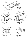
- Fig. 2
- einen schematisch ausschnittsweise dargestellten Schnitt quer durch den Halterbereich des Querträgers und die In- strumententafel im Bereich II von Fig. 1 gemäß dem ersten Ausführungsbeispiel,
- Fig. 3
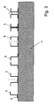
- einen Querträger mit sechs schematisch dargestellten, einstückig mit dem Querträger ausgebildeten Haltern,
- Fig. 4
- einen Ausschnitt eines Querträgers gemäß einem weiteren Ausführungsbeispiel mit Halter und teilweise dargestelltem, hieran angebrachten Bauteil, wobei ein Aufprallschutz vor- gesehen ist, und
- Fig. 5
- einen Ausschnitt eines Querträgers gemäß einem weiteren Ausführungsbeispiel mit Halter mit Aufprallschutz und teil- weise dargestelltem, hieran angebrachten Bauteil, wobei im linken Teil der Normalzustand und im rechten Teil der Zu- stand nach einem Aufprall mit Deformation dargestellt ist, und
- Fig. 6
- einen Ausschnitt eines zweischaligen Querträgers mit im Wesentlichen zylindrischen Halbschalen gemäß einem wei- teren Ausführungsbeispiel, und
- Fig. 7
- einen Ausschnitt eines zweischaligen Querträgers mit im Wesentlichen U-förmigen Halbschalen gemäß einem weite- ren Ausführungsbeispiel, und
- Fig. 8
- einen Ausschnitt eines zweischaligen Querträgers mit im Wesentlichen Z-förmigen Halbschalen gemäß einem weite- ren Ausführungsbeispiel, und
- Fig. 9
- einen Querschnitt durch den Querträger nach Fig. 8, und
- Fig. 10
- schematisch einen Querträger nach Fig. 8 mit zur Z- und X- Achse geneigten Schalenflächen.
- Fig. 1
- a top view of a cross member with instrument panel,
- Fig. 2
- 1 schematically shows a section through the holder area of the cross member and the instrument panel in area II of FIG. 1 according to the first embodiment, FIG.
- Fig. 3
- a cross member with six schematically illustrated, integrally formed with the cross member holders
- Fig. 4
- a section of a cross member according to a further embodiment with a holder and partially illustrated, attached thereto component, wherein an impact protection is provided, and
- Fig. 5
- a detail of a cross member according to another embodiment with holder with impact protection and partially represented, attached thereto component, wherein in the left part of the normal state and in the right part of the state after an impact with deformation is shown, and
- Fig. 6
- a section of a bivalve cross member having substantially cylindrical half-shells according to a further embodiment, and
- Fig. 7
- a detail of a bivalve cross member having substantially U-shaped half-shells according to a further embodiment, and
- Fig. 8
- a detail of a bivalve cross member having substantially Z-shaped half-shells according to a further embodiment, and
- Fig. 9
- a cross section through the cross member of FIG. 8, and
- Fig. 10
- schematically a cross member of FIG. 8 with inclined to the Z and X axis shell surfaces.
Ein als Hybridbauteil ausgebildeter Querträger 1, bestehend aus zwei miteinander
verbundenen Blechhalbschalen (nicht näher dargestellt), die eine
Kunststoffstruktur 3 aufweisen, welche bereichsweise um und in die Blechhalbschalen
gespritzt ist, weist gemäß dem ersten, in den Figuren 1 und 2
dargestellten Ausführungsbeispiel einen in der Kunststoffstruktur 3 integriert
in Form einer Schwalbenschwanzführung 4 ausgebildeten Halter 5 auf, welcher
zur Befestigung der Instrumententafel 6 dient. Der Halter 5 verläuft vorliegend
in Querrichtung des Querträgers 1. Zur leichteren Einführbarkeit der
Instrumententafel 6, genauer gesagt des an der Instrumententafel 6 integriert
ein- oder mehrstückig ausgebildeten Gegenstücks zur schwalbenschwanzförmigen
Nut in der Kunststoffstruktur 3 ist das offene Nutende aufgeweitet
ausgebildet, so dass ein einfaches Einführen und eine Zentrierung ohne
Verklemmen möglich ist. Das andere Nutende ist mit einem Anschlag verschlossen,
welcher derart ausgebildet ist, dass er die Endposition der Instrumententafel
6 definiert, so dass die Instrumententafel 6 bei der Montage
einfach bis zum Anschlag eingeschoben wird. Die Fixierung der Instrumententafel
6 im Querträger 1 erfolgt mittels eines Stifts (nicht dargestellt), kann
jedoch auch auf beliebige andere Weise erfolgen, beispielsweise durch eine
Klemmschraube, einen Bolzen oder gegebenenfalls auch durch eine Clipsverbindung,
wobei ein Teil, beispielsweise eine Öffnung, am Querträger 1
und ein Teil, beispielsweise ein Federarm, der in die Öffnung eingreift, an
der Instrumententafel 6 ausgebildet ist.A trained as a hybrid
Gemäß einem zweiten Ausführungsbeispiel, das nicht in der Zeichnung dargestellt ist, ist am Querträger einstückig mit der Kunststoffstruktur ein T-förmiges Profil ausgebildet, das in eine entsprechend ausgebildete Nut an einem am Querträger anzubringenden Bauteil, beispielsweise eine Instrumententafel, eingeführt wird. Ist das Bauteil von der Seite her aufgeschoben, so erfolgt eine Fixierung mittels eines Stifts, der in eine Öffnung im Bauteil, welche bei exakter Positionierung mit einer zweiten Öffnung im T-förmigen Profil fluchtet, eingeführt wird.According to a second embodiment, not shown in the drawing is, is on the cross member in one piece with the plastic structure a T-shaped Profile trained, the in an appropriately trained groove on a component to be attached to the cross member, for example an instrument panel, is introduced. If the component is pushed from the side, Thus, a fixation by means of a pin, which takes place in an opening in the component, which with exact positioning with a second opening in the T-shaped Profile is aligned, is introduced.
Entsprechend einer Variante des zweiten Ausführungsbeispiels ist, wie beim zweiten Ausführungsbeispiel ein T-förmiges Profil am Querträger ausgebildet, jedoch ist dieses durch eine Doppel-T-förmige Metalleinlage, welche eingespritzt ist, verstärkt, so dass größere Kräfte aufgenommen werden können. Die Funktion entspricht jedoch der des zweiten AusführungsbeiSpiels.According to a variant of the second embodiment, as in second embodiment, a T-shaped profile formed on the cross member, however, this is by a double T-shaped metal insert, which injected, reinforced, so that larger forces are absorbed can. However, the function corresponds to that of the second embodiment.
Gemäß einer zweiten Variante des zweiten Ausführungsbeispiels ist die Metalleinlage I-förmig ausgebildet, so dass im Querbereich keine Metallverstärkung vorgesehen ist. Diese Ausgestaltung ermöglicht eine biegesteife Ausgestaltung in einer Richtung sowie in -Z -Richtung (auf den Querträger zu) und eine weichere Ausgestaltung in +Z-Richtung (vom Querträger weg).According to a second variant of the second embodiment, the metal insert I-shaped, so that in the transverse region no metal reinforcement is provided. This embodiment allows a rigid design in one direction and in -Z direction (towards the cross member too) and a softer configuration in the + Z direction (away from the cross member).
Als drittes Ausführungsbeispiel ist am Querträger ein Bereich mit einem L-förmig überstehenden Profil einstückig ausgebildet. Dabei kann es sich um einen vollständig durch einen Teil der Kunststoffstruktur gebildeten Bereich des Querträgers handeln. Gemäß einer ersten Variante ist eine Metalleinlage vorgesehen, die vollständig in die Kunststoffstruktur eingespritzt ist und gemäß einer zweiten Variante wird das L-förmig überstehende Profil durch ein auf seiner einen Seite in die Kunststoffstruktur eingespritztes Metallprofil gebildet, wobei das Metallprofil auf der eingespritzten Seite beispielsweise L- oder T-förmig ausgebildet sein kann.As a third embodiment, an area with an L-shaped on the cross member protruding profile integrally formed. It can be about a fully formed by a part of the plastic structure area the cross member act. According to a first variant is a metal insert provided, which is completely injected into the plastic structure and according to a second variant, the L-shaped protruding profile is a formed on its one side in the plastic structure injected metal profile, wherein the metal profile on the injected side, for example, L- or T-shaped may be formed.
Gemäß einem vierten Ausführungsbeispiel ist am Querträger 1 ein Z-förmiges
Profil einstückig mit der Kunststoffstruktur 3 ausgebildet, wie in Fig.
3 ganz links dargestellt. Zur Vereinfachung des Einführens ist das Profil am
Einführende dünner ausgebildet und das seitlich vorstehende Ende kürzer
ausgebildet. Ebenso kann sich die Höhe in Montagerichtung verringern. Das
am Querträger 1 anzubringende Bauteil weist eine L-förmige Nut auf, deren
Abmessungen mit denen des Z-förmigen Profils abgestimmt sind.According to a fourth embodiment, the
Entsprechend einem fünften Ausführungsbeispiel, das in Fig. 3 als zweites
von links dargestellt ist, ist ein U-förmiges Profil vorgesehen, wobei das Profil
derart am Querträger 1 angeordnet ist, dass es offen ist und seitlich überstehende
Ränder aufweist. Das Bauteil, welches am Querträger 1 anzubringen
ist, weist eine hinterschnittene Nut auf. Dieses Ausführungsbeispiel entspricht
von seiner Funktion her dem in Fig. 3 ganz rechts dargestellten Ausführungsbeispiel
gemäß dem zwei voneinander abgewandte C-förmige Profile
vorgesehen sind. According to a fifth embodiment, in Fig. 3 as a second
shown from the left, a U-shaped profile is provided, the profile
is arranged on the
Gemäß dem in Fig. 3 als drittes von links dargestellten Ausführungsbeispiel
sind zwei spiegelbildlich zueinander angeordnete Z-förmige Profile vorgesehen,
deren vom Querträger 1 entfernte Schenkel aufeinander zu zeigen.
Zwischen die beiden Z-förmigen Profile wird ein T-förmiges Profil eingeführt,
das am Bauteil vorgesehen ist, das am Querträger 1 befestigt werden soll.
Von seiner Funktion her entspricht dieses Ausführungsbeispiel dem rechts
hiervon in Fig. 3 dargestellten Ausführungsbeispiel, welches zwei C-förmige
Profile aufweist, die einander zugewandt sind.According to the embodiment shown in Fig. 3 as a third from the left
two mirror-inverted Z-shaped profiles are provided,
their leg remote from the
Entsprechend dem in Fig. 3 als zweites von rechts dargestellten Ausführungsbeispiel
ist das am Querträger 1 ausgebildete Profil doppel-T-förmig
ausgebildet. Das am Querträger 1 anzubringende Bauteil weist eine T-Nut
auf, die in ihren Abmessungen etwa denen des Profils am Querträger 1 entspricht.Corresponding to the embodiment shown in Fig. 3 as a second from the right
is formed on the
Entsprechend von nicht näher erläuterten Varianten zu den in Fig. 3 dargestellten
Ausführungsbeispielen sind Verstärkungselemente in den Profilen
vorgesehen, welche entsprechend den dick durchgezogenen Linien in Fig. 3
verlaufen und zumindest bereichsweise von der Kunststoffstruktur 3 umgeben
sind oder nur aus Kunststoff bestehen.Corresponding to unspecified variants to those shown in Fig. 3
Embodiments are reinforcing elements in the profiles
provided corresponding to the thick solid lines in Fig. 3rd
run and at least partially surrounded by the
Gemäß einem weiteren, nicht in der Zeichnung dargestellten Ausführungsbeispiel ist in der Kunststoffstruktur eine als Halter dienende Tasche ausgebildet, in welche ein Gegenstück des am Querträger zu befestigenden Bauteils eingesteckt wird. Die Fixierung kann mittels einer Clipsverbindung, eines Stifts, mittels Einklebens oder auf sonstige Weise erfolgen. Gemäß einer Variante ist die Tasche verstärkt ausgebildet, wobei ein verstärkendes Einlegeteil in den Kunststoff eingespritzt ist oder der metallische Teil des Querträgers entsprechend ausgebildet ist. Alternativ kann an Stelle einer Tasche auch eine Lasche ausgebildet sein. According to another, not shown in the drawing embodiment a pocket serving as a holder is formed in the plastic structure, in which a counterpart of the cross member to be fastened component is inserted. The fixation can by means of a clip connection, a Stick, by gluing or otherwise done. According to a variant the pocket is reinforced, with a reinforcing insert injected into the plastic or the metallic part of the cross member is designed accordingly. Alternatively, instead of a bag also be designed a tab.
Im Falle einer zweischaligen Ausgestaltung der Querträgergrundstruktur kann auch der überstehende Bund als Führung für ein am Querträger anzubringendes Bauteil dienen, wobei der Bund in Verbindung mit anderen Elementen direkt als Halter dient, so dass keine nachträglich am Querträger anzubringenden Halter, wie beim Stand der Technik, verwendet werden müssen. Das anzubringende Bauteil weist eine Nut auf, in welche der Bund bei der Montage eingeführt wird. Die Befestigung kann auf bekannte Weise erfolgen. Zum einfacheren Einführen kann der Bund angefast sein und/oder die Nut bei einer Einführung auf den Bund zu oben erweitert oder bei einer Einführung von der Seite seitlich erweitert ausgebildet sein.In the case of a two-shell embodiment of the cross member base structure can also be the projecting collar as a guide for a to be attached to the cross member Serve component, the federal government in conjunction with other elements directly serves as a holder, so that no later to be attached to the cross member Holder, as in the prior art, must be used. The component to be attached has a groove, in which the federal government at the assembly is introduced. The attachment can be done in a known manner. For ease of insertion, the collar may be chamfered and / or the groove extended at an introduction to the federal above or at a Introduction from the side to be laterally expanded.
Ein Beispiel für einen aus zwei Schalen 10 bestehenden Querträger ist in
Fig. 6 dargestellt. Zusätzlich zum Bund 11 sind in die Schalen 10 Halter 5
eingeformt. Die Halter 5 sind im vorliegenden Ausführungsbeispiel im Querschnitt
von der Form eines Sechsecks oder eines Kreises in den Schalen 10
ausgeführt, wobei beliebige Ausgestaltungen, insbesondere weitere Polygonformen
möglich sind.An example of a two
Alternativ zu den im Wesentlichen halbzylindrischen Schalen der Fig. 6, ist in
Fig. 7 ein Querträger aus zwei im Wesentlichen U-förmigen Schalen 10 mit
unterschiedlich langen Schenkeln skizziert. Jeweils ein Halter 5 ist in Form
einer Tasche im oberen Bereich der ersten, im Querschnitt kleineren Schale
10, sowie im unteren Bereich der zweiten im Querschnitt größeren Schale
10, ausgebildet. Alternativ können die beiden Halter auch nur in einer der
beiden Schalen 10 ausgebildet sein.As an alternative to the essentially semi-cylindrical shells of FIG. 6, FIG
Fig. 7 is a cross member of two substantially
In einer weiteren, in Fig. 8 dargestellten Variante besteht der Querträger 1
aus zwei Z-förmigen Schalen 10. Ein Schnitt im Bereich eines Halters 5
durch den Querträger 1 ist in Fig. 9 gezeigt. Durch das Abheben eines Schalenteils
10 im Endbereich bzw. im Bereich des Bundes 11 entsteht wird ein
Halter 5 gebildet In a further variant, shown in FIG. 8, the
Abhängig von der Einbaulage des Querträgers im Fahrzeug, ist es möglich
die Ausbildung des Halters auf die bevorzugte Montagerichtung eines vom
Halter 5 aufzunehmenden Teiles abzustimmen. Ein Beispiel hierfür ist in Fig.
10 schematisch skizziert. Ein Querträger 1 ist mit den Flächen seiner Schalen
10 geneigt zur Z- und X-Richtung angeordnet. Die Montagerichtung eines
anzubauenden Teiles, angedeutet durch einen Pfeil, verläuft in X-Richtung.
Zur einfacheren Aufnahme ist auch der Halter 5 im Wesentlichen in X-Richtung
orientiert, wodurch dieser mit seinen Aufnahmeflächen im Wesentlichen
geneigt zur Querträgerachse bzw. zu den die Schalen 10 des Querträgers
bildenden Flächen angeordnet ist.Depending on the mounting position of the cross member in the vehicle, it is possible
the formation of the holder on the preferred mounting direction of the
To tune
Ein dem Bund entsprechender Vorsprung, der als Halter dient, kann auch an einer beliebigen anderen Außenfläche des Querträgers durch die Kunststoffstruktur ausgebildet sein, verstärkt oder unverstärkt, je nach zu erwartender Belastung.A corresponding projection to the federal government, which serves as a holder, can also any other outer surface of the cross member through the plastic structure be formed, reinforced or unreinforced, depending on the expected Burden.
Die Abmessungen der Profile der Halter und der Gegenstücke am hieran anzubringenden Bauteil können bedarfsgerecht ausgebildet werden, so dass bestimmte gewünschte Eigenschaften erzielt werden können, wie insbesondere ein gewisses Spiel in eine bestimmte Richtung oder eine spielfreie und somit steife Anbindung in einer bestimmten Richtung. Dies kann insbesondere zur Erhöhung der Crashsicherheit gezielt eingesetzt werden, so dass beispielsweise die Anbindung der Instrumententafel in +Z-Richtung, das heißt vom Querträger weg, steif, also keine Durchbiegung erfolgen kann, wie beispielsweise für eine Airbag-Auslösung erforderlich, und in -Z-Richtung, das heißt auf den Querträger zu, in einem gewissen Bereich deformierbar ausgebildet sein kann, so dass ein gewisser Schutz im Falle eines Kopfaufpralls gegeben ist Die Freigabe in -Z-Richtung kann kraftabhängig sein, so dass ein Klappem im Normalbetrieb vermieden werden kann. Dies ist beispielsweise durch eine Anlage mit Reibung in einem Bereich des Profils möglich. The dimensions of the profiles of the holder and the counterparts on this to be mounted component can be formed as needed, so that certain desired properties can be achieved, in particular a certain game in a certain direction or a play-free and thus stiff connection in a certain direction. This can be special be specifically used to increase the crash safety, so that, for example the connection of the instrument panel in + Z-direction, that is away from the cross member, stiff, so no bending can take place, such as required for airbag deployment, and in -Z direction, the means on the cross member, formed deformable in a certain range can be, so some protection in case of a head impact The release in -Z direction can be force-dependent, so that a Klappem can be avoided in normal operation. This is for example through a system with friction in one area of the profile possible.
Fig. 4 zeigt einen Teil eines Querträgers 1 mit angeformten Halter 5 und einen
Teil eines hieran angebrachten Bauteils 7. Der Halter 5 umfasst hierbei
eine Aufprallschutzvorrichtung 8, welche sicherstellt, dass im Falle eines
Crashs, insbesondere bei einem Kopfaufprall eines Insassens des Fahrzeugs,
eine gewisse, definierte Deformation, vorliegend eine Verschiebung
des Bauteils 7 in Pfeilrichtung um eine Strecke s, möglich ist, so dass das
Verletzungsrisiko deutlich gesenkt werden kann.Fig. 4 shows a part of a
Um eine Verschiebbarkeit bei im Normalbetrieb sicherer Fixierung sicherzustellen,
weist der Halter 5 ein oben offenes U-förmiges Profil auf, wobei auf
den Innenseiten der Schenkel zur Aufnahme eines verbreiterten Bereichs
des Befestigungsbereichs des Bauteils 7 nutförmige Aufnahmen vorgesehen
sind, die nach oben, also zum Bauteil 7 hin abgeschrägt sind, so dass im
Crashfall eine kontinuierliche Verformung des Halters 5 und/oder des Befestigungsbereichs
des Bauteils 7 und somit eine Verschiebung nach unten in
den Halter 5 hinein möglich ist. Der untere Bereich des Halters 5 weist eine
Breite auf, welche etwa des Abstands der nutförmigen Aufnahmen voneinander
im Nutgrund oder der Breite des Bauteils 7 im breitesten Teil des Befestigungsbereichs
entspricht.In order to ensure a shiftability during normal operation secure fixation
the
Die Verschiebung des Bauteils 7 gegenüber dem Halter 5 wird durch eine
gewisse Elastizität und/oder plastische Verformbarkeit gewährleistet und
durch eine Anlage einer Fläche 9 des Bauteils 7 an einem Anlagebereich
des Halters begrenzt. Bei der Verschiebung kann sowohl der Halter 5 als
auch das Bauteil 7 bevorzugt elastisch, gegebenenfalls auch plastisch verformt
werden.The displacement of the
Der Halter 5 gemäß dem in Fig. 5 dargestellten folgenden Ausführungsbeispiel
weist ebenfalls eine Aufprallschutzvorrichtung 8 auf, welche eine Verschiebbarkeit
um eine belastungsabhängige Strecke s des Bauteils 7 auf
den Querträger 1 zu im Bedarfsfall ermöglicht. Die Ausgestaltung des Befestigungsbereichs
des Bauteils 7 entspricht der des vorherigen Ausführungsbeispiels.
Die Funktion ist im Wesentlichen die Gleiche, wie im zuvor beschriebenen
Ausführungsbeispiel, jedoch erfolgt ausschließlich eine elastische
Verformung des Halters 5, welcher sich aufweitet. Die Schräge, welche
in ihrer Funktion der o. g. Abschrägung entspricht, ist hierbei aber deutlich
flacher ausgebildet, so dass ein kontinuierlicher Anstieg der Kraft in Abhängigkeit
des Verformungsweges bis zum Anschlag der Anlageflächen gegeben
ist. Die Verschiebung des Bauteils 7 gegenüber dem Halter 5 wird eine
Anlage einer Fläche 9 des Bauteils 7 an einem Anlagebereich des Halters
begrenzt.The
Claims (15)
Applications Claiming Priority (2)
| Application Number | Priority Date | Filing Date | Title |
|---|---|---|---|
| DE102004030689A DE102004030689A1 (en) | 2004-06-24 | 2004-06-24 | crossbeam |
| DE102004030689 | 2004-06-24 |
Publications (3)
| Publication Number | Publication Date |
|---|---|
| EP1609703A2 true EP1609703A2 (en) | 2005-12-28 |
| EP1609703A3 EP1609703A3 (en) | 2006-10-04 |
| EP1609703B1 EP1609703B1 (en) | 2008-12-17 |
Family
ID=34937591
Family Applications (1)
| Application Number | Title | Priority Date | Filing Date |
|---|---|---|---|
| EP05013399A Not-in-force EP1609703B1 (en) | 2004-06-24 | 2005-06-22 | Transverse beam |
Country Status (3)
| Country | Link |
|---|---|
| EP (1) | EP1609703B1 (en) |
| AT (1) | ATE417778T1 (en) |
| DE (2) | DE102004030689A1 (en) |
Cited By (4)
| Publication number | Priority date | Publication date | Assignee | Title |
|---|---|---|---|---|
| WO2022079636A1 (en) * | 2020-10-13 | 2022-04-21 | Polestar Performance Ab | Cross car beam assembly with tapered joint |
| US11318993B1 (en) | 2020-10-13 | 2022-05-03 | Polestar Performance Ab | Modular cross car beam assembly |
| EP4122803A1 (en) * | 2020-11-11 | 2023-01-25 | Volkswagen AG | Instrument panel holder for a motor vehicle |
| US11572105B2 (en) | 2020-10-13 | 2023-02-07 | Polestar Performance Ab | Cross car beam assembly with integral safety unit |
Families Citing this family (2)
| Publication number | Priority date | Publication date | Assignee | Title |
|---|---|---|---|---|
| DE102012007973A1 (en) * | 2012-04-20 | 2013-10-24 | GM Global Technology Operations LLC (n. d. Gesetzen des Staates Delaware) | Device for attaching a compressible surface structure to a body part of a vehicle |
| DE102017200113B4 (en) | 2017-01-05 | 2020-07-09 | Volkswagen Aktiengesellschaft | Bumper cross member for a motor vehicle and motor vehicle with such a bumper cross member |
Family Cites Families (11)
| Publication number | Priority date | Publication date | Assignee | Title |
|---|---|---|---|---|
| AT22852B (en) * | 1902-12-04 | 1906-01-25 | Arthur Edelmann | Process for the manufacture of electrodes for electric arc lamps. |
| DE19626441B4 (en) * | 1996-06-20 | 2004-03-25 | Sommer-Allibert-Lignotock Gmbh | Cockpit for motor vehicles |
| US5934733A (en) * | 1997-12-19 | 1999-08-10 | General Motors Corporation | Extruded instrument panel structure |
| DE19854076C1 (en) * | 1998-11-24 | 2000-04-13 | Daimler Chrysler Ag | Flanged profile for motor vehicle bodywork has sheet metal strip of T-shaped cross section having flanges fitting into hollow profile tube |
| JP2001213139A (en) * | 1999-11-26 | 2001-08-07 | Inoac Corp | Air guide duct for vehicle |
| DE20008201U1 (en) * | 2000-05-08 | 2000-07-27 | Benteler Werke Ag | Dashboard support |
| DE10064522A1 (en) * | 2000-09-07 | 2002-03-21 | Behr Gmbh & Co | Component for a motor vehicle |
| DE10044379A1 (en) * | 2000-09-08 | 2002-04-04 | Behr Gmbh & Co | Component for a motor vehicle |
| DE10144714A1 (en) * | 2001-09-11 | 2003-03-27 | Behr Gmbh & Co | Hybrid carrier for a motor vehicle |
| JP2003154874A (en) * | 2001-11-16 | 2003-05-27 | Yazaki Corp | Instrument panel module and transmitting system for vehicle |
| DE10240395A1 (en) * | 2002-09-02 | 2004-03-18 | Lisa Dräxlmaier GmbH | Cross-member for vehicle incorporates curved tubes or curved bars in area between A-pillar and propeller shaft tunnel, tubes being made from fiber-reinforced plastic and bars having metal-plastic hybrid structure |
-
2004
- 2004-06-24 DE DE102004030689A patent/DE102004030689A1/en not_active Withdrawn
-
2005
- 2005-06-22 AT AT05013399T patent/ATE417778T1/en not_active IP Right Cessation
- 2005-06-22 EP EP05013399A patent/EP1609703B1/en not_active Not-in-force
- 2005-06-22 DE DE502005006250T patent/DE502005006250D1/en active Active
Non-Patent Citations (1)
| Title |
|---|
| None |
Cited By (5)
| Publication number | Priority date | Publication date | Assignee | Title |
|---|---|---|---|---|
| WO2022079636A1 (en) * | 2020-10-13 | 2022-04-21 | Polestar Performance Ab | Cross car beam assembly with tapered joint |
| US11318993B1 (en) | 2020-10-13 | 2022-05-03 | Polestar Performance Ab | Modular cross car beam assembly |
| US11345402B2 (en) | 2020-10-13 | 2022-05-31 | Polestar Performance Ab | Cross car beam assembly with tapered joint |
| US11572105B2 (en) | 2020-10-13 | 2023-02-07 | Polestar Performance Ab | Cross car beam assembly with integral safety unit |
| EP4122803A1 (en) * | 2020-11-11 | 2023-01-25 | Volkswagen AG | Instrument panel holder for a motor vehicle |
Also Published As
| Publication number | Publication date |
|---|---|
| EP1609703A3 (en) | 2006-10-04 |
| ATE417778T1 (en) | 2009-01-15 |
| DE502005006250D1 (en) | 2009-01-29 |
| EP1609703B1 (en) | 2008-12-17 |
| DE102004030689A1 (en) | 2006-01-19 |
Similar Documents
| Publication | Publication Date | Title |
|---|---|---|
| EP0798197A1 (en) | Front-part of a vehicle | |
| DE102004019089B4 (en) | Vehicle body structure | |
| EP1902927A2 (en) | Vehicle body for a motor vehicle | |
| EP1609703B1 (en) | Transverse beam | |
| EP3442851A1 (en) | Arrangement of a fastening structure on a structural component of a motor vehicle with a fibre inlay element | |
| EP1816031A2 (en) | Fastening system | |
| DE102015113773B3 (en) | Bumper arrangement for a motor vehicle | |
| DE10140338A1 (en) | Adapter for joining pulling handle to inner side of car door, assembled of two separate profiles in order to yield in case of impact | |
| DE102008025740A1 (en) | Bracket for use in bracket arrangement of retaining grip in motor vehicle, has U-shaped sections with journal for attaching bracket at motor vehicle, where retaining grip is attached at another journal | |
| DE102019205021A1 (en) | Towing device for a motor vehicle | |
| DE102014106719B4 (en) | Structure of a steering support member | |
| EP3947021B1 (en) | Deformation device for a motor vehicle, and motor vehicle comprising a deformation device | |
| DE102012023785A1 (en) | Device for stress-free fastening of e.g. front headlight to transverse structure of body of motor vehicle, has angle part arranged at holding part by connection element such that angle part is moved in direction against one of components | |
| EP3110666B1 (en) | Fixing device for a radiator grill and a bumper on a front end mount of a vehicle | |
| DE102017206133B3 (en) | Wiper assembly for a motor vehicle | |
| DE102018205272A1 (en) | Arrangement of a component, in particular a sensor, on a plastic mounting support of a motor vehicle | |
| DE10058998C1 (en) | U-shaped vehicle bumper unit has retaining collars and fixing rail fitted together by fixings having ideal break points to reduce crash deformation to vehicle parts | |
| EP3501900B1 (en) | Internal module for a cargo compartment of a vehicle, cargo compartment cladding and method for producing an internal module | |
| DE102011018388B4 (en) | Cross member for a body of a motor vehicle | |
| DE102017209986A1 (en) | Seat rail pair for a vehicle seat | |
| DE102019203758B4 (en) | Structural component for a body of a vehicle and vehicle body | |
| DE102017201258B4 (en) | Carrier for storing vehicle equipment for a motor vehicle | |
| DE102019211376A1 (en) | Paneling arrangement for interior equipment of a motor vehicle, a motor vehicle door and motor vehicle | |
| DE102020116604A1 (en) | Vehicle frame with two side members | |
| DE102015007754A1 (en) | Battery holder for a motor vehicle |
Legal Events
| Date | Code | Title | Description |
|---|---|---|---|
| PUAI | Public reference made under article 153(3) epc to a published international application that has entered the european phase |
Free format text: ORIGINAL CODE: 0009012 |
|
| AK | Designated contracting states |
Kind code of ref document: A2 Designated state(s): AT BE BG CH CY CZ DE DK EE ES FI FR GB GR HU IE IS IT LI LT LU MC NL PL PT RO SE SI SK TR |
|
| AX | Request for extension of the european patent |
Extension state: AL BA HR LV MK YU |
|
| PUAL | Search report despatched |
Free format text: ORIGINAL CODE: 0009013 |
|
| AK | Designated contracting states |
Kind code of ref document: A3 Designated state(s): AT BE BG CH CY CZ DE DK EE ES FI FR GB GR HU IE IS IT LI LT LU MC NL PL PT RO SE SI SK TR |
|
| AX | Request for extension of the european patent |
Extension state: AL BA HR LV MK YU |
|
| 17P | Request for examination filed |
Effective date: 20070404 |
|
| AKX | Designation fees paid |
Designated state(s): AT BE BG CH CY CZ DE DK EE ES FI FR GB GR HU IE IS IT LI LT LU MC NL PL PT RO SE SI SK TR |
|
| 17Q | First examination report despatched |
Effective date: 20070921 |
|
| GRAP | Despatch of communication of intention to grant a patent |
Free format text: ORIGINAL CODE: EPIDOSNIGR1 |
|
| GRAS | Grant fee paid |
Free format text: ORIGINAL CODE: EPIDOSNIGR3 |
|
| GRAS | Grant fee paid |
Free format text: ORIGINAL CODE: EPIDOSNIGR3 |
|
| GRAA | (expected) grant |
Free format text: ORIGINAL CODE: 0009210 |
|
| AK | Designated contracting states |
Kind code of ref document: B1 Designated state(s): AT BE BG CH CY CZ DE DK EE ES FI FR GB GR HU IE IS IT LI LT LU MC NL PL PT RO SE SI SK TR |
|
| REG | Reference to a national code |
Ref country code: GB Ref legal event code: FG4D Free format text: NOT ENGLISH |
|
| REG | Reference to a national code |
Ref country code: CH Ref legal event code: EP |
|
| REG | Reference to a national code |
Ref country code: IE Ref legal event code: FG4D Free format text: LANGUAGE OF EP DOCUMENT: GERMAN |
|
| REF | Corresponds to: |
Ref document number: 502005006250 Country of ref document: DE Date of ref document: 20090129 Kind code of ref document: P |
|
| PG25 | Lapsed in a contracting state [announced via postgrant information from national office to epo] |
Ref country code: LT Free format text: LAPSE BECAUSE OF FAILURE TO SUBMIT A TRANSLATION OF THE DESCRIPTION OR TO PAY THE FEE WITHIN THE PRESCRIBED TIME-LIMIT Effective date: 20081217 |
|
| PG25 | Lapsed in a contracting state [announced via postgrant information from national office to epo] |
Ref country code: SI Free format text: LAPSE BECAUSE OF FAILURE TO SUBMIT A TRANSLATION OF THE DESCRIPTION OR TO PAY THE FEE WITHIN THE PRESCRIBED TIME-LIMIT Effective date: 20081217 Ref country code: FI Free format text: LAPSE BECAUSE OF FAILURE TO SUBMIT A TRANSLATION OF THE DESCRIPTION OR TO PAY THE FEE WITHIN THE PRESCRIBED TIME-LIMIT Effective date: 20081217 Ref country code: PL Free format text: LAPSE BECAUSE OF FAILURE TO SUBMIT A TRANSLATION OF THE DESCRIPTION OR TO PAY THE FEE WITHIN THE PRESCRIBED TIME-LIMIT Effective date: 20081217 Ref country code: NL Free format text: LAPSE BECAUSE OF FAILURE TO SUBMIT A TRANSLATION OF THE DESCRIPTION OR TO PAY THE FEE WITHIN THE PRESCRIBED TIME-LIMIT Effective date: 20081217 |
|
| NLV1 | Nl: lapsed or annulled due to failure to fulfill the requirements of art. 29p and 29m of the patents act | ||
| REG | Reference to a national code |
Ref country code: IE Ref legal event code: FD4D |
|
| PG25 | Lapsed in a contracting state [announced via postgrant information from national office to epo] |
Ref country code: EE Free format text: LAPSE BECAUSE OF FAILURE TO SUBMIT A TRANSLATION OF THE DESCRIPTION OR TO PAY THE FEE WITHIN THE PRESCRIBED TIME-LIMIT Effective date: 20081217 Ref country code: BG Free format text: LAPSE BECAUSE OF FAILURE TO SUBMIT A TRANSLATION OF THE DESCRIPTION OR TO PAY THE FEE WITHIN THE PRESCRIBED TIME-LIMIT Effective date: 20090317 Ref country code: RO Free format text: LAPSE BECAUSE OF FAILURE TO SUBMIT A TRANSLATION OF THE DESCRIPTION OR TO PAY THE FEE WITHIN THE PRESCRIBED TIME-LIMIT Effective date: 20081217 Ref country code: IE Free format text: LAPSE BECAUSE OF FAILURE TO SUBMIT A TRANSLATION OF THE DESCRIPTION OR TO PAY THE FEE WITHIN THE PRESCRIBED TIME-LIMIT Effective date: 20081217 Ref country code: ES Free format text: LAPSE BECAUSE OF FAILURE TO SUBMIT A TRANSLATION OF THE DESCRIPTION OR TO PAY THE FEE WITHIN THE PRESCRIBED TIME-LIMIT Effective date: 20090328 |
|
| PG25 | Lapsed in a contracting state [announced via postgrant information from national office to epo] |
Ref country code: SE Free format text: LAPSE BECAUSE OF FAILURE TO SUBMIT A TRANSLATION OF THE DESCRIPTION OR TO PAY THE FEE WITHIN THE PRESCRIBED TIME-LIMIT Effective date: 20090317 Ref country code: PT Free format text: LAPSE BECAUSE OF FAILURE TO SUBMIT A TRANSLATION OF THE DESCRIPTION OR TO PAY THE FEE WITHIN THE PRESCRIBED TIME-LIMIT Effective date: 20090518 Ref country code: IS Free format text: LAPSE BECAUSE OF FAILURE TO SUBMIT A TRANSLATION OF THE DESCRIPTION OR TO PAY THE FEE WITHIN THE PRESCRIBED TIME-LIMIT Effective date: 20090417 Ref country code: CZ Free format text: LAPSE BECAUSE OF FAILURE TO SUBMIT A TRANSLATION OF THE DESCRIPTION OR TO PAY THE FEE WITHIN THE PRESCRIBED TIME-LIMIT Effective date: 20081217 |
|
| PG25 | Lapsed in a contracting state [announced via postgrant information from national office to epo] |
Ref country code: SK Free format text: LAPSE BECAUSE OF FAILURE TO SUBMIT A TRANSLATION OF THE DESCRIPTION OR TO PAY THE FEE WITHIN THE PRESCRIBED TIME-LIMIT Effective date: 20081217 |
|
| PLBE | No opposition filed within time limit |
Free format text: ORIGINAL CODE: 0009261 |
|
| STAA | Information on the status of an ep patent application or granted ep patent |
Free format text: STATUS: NO OPPOSITION FILED WITHIN TIME LIMIT |
|
| PG25 | Lapsed in a contracting state [announced via postgrant information from national office to epo] |
Ref country code: DK Free format text: LAPSE BECAUSE OF FAILURE TO SUBMIT A TRANSLATION OF THE DESCRIPTION OR TO PAY THE FEE WITHIN THE PRESCRIBED TIME-LIMIT Effective date: 20081217 |
|
| 26N | No opposition filed |
Effective date: 20090918 |
|
| BERE | Be: lapsed |
Owner name: BEHR G.M.B.H. & CO. KG Effective date: 20090630 |
|
| PG25 | Lapsed in a contracting state [announced via postgrant information from national office to epo] |
Ref country code: MC Free format text: LAPSE BECAUSE OF NON-PAYMENT OF DUE FEES Effective date: 20090630 |
|
| REG | Reference to a national code |
Ref country code: CH Ref legal event code: PL |
|
| GBPC | Gb: european patent ceased through non-payment of renewal fee |
Effective date: 20090622 |
|
| REG | Reference to a national code |
Ref country code: FR Ref legal event code: ST Effective date: 20100226 |
|
| PG25 | Lapsed in a contracting state [announced via postgrant information from national office to epo] |
Ref country code: LI Free format text: LAPSE BECAUSE OF NON-PAYMENT OF DUE FEES Effective date: 20090630 Ref country code: FR Free format text: LAPSE BECAUSE OF NON-PAYMENT OF DUE FEES Effective date: 20090630 Ref country code: CH Free format text: LAPSE BECAUSE OF NON-PAYMENT OF DUE FEES Effective date: 20090630 |
|
| PG25 | Lapsed in a contracting state [announced via postgrant information from national office to epo] |
Ref country code: GB Free format text: LAPSE BECAUSE OF NON-PAYMENT OF DUE FEES Effective date: 20090622 |
|
| PG25 | Lapsed in a contracting state [announced via postgrant information from national office to epo] |
Ref country code: BE Free format text: LAPSE BECAUSE OF NON-PAYMENT OF DUE FEES Effective date: 20090630 |
|
| PG25 | Lapsed in a contracting state [announced via postgrant information from national office to epo] |
Ref country code: AT Free format text: LAPSE BECAUSE OF NON-PAYMENT OF DUE FEES Effective date: 20090622 |
|
| PG25 | Lapsed in a contracting state [announced via postgrant information from national office to epo] |
Ref country code: GR Free format text: LAPSE BECAUSE OF FAILURE TO SUBMIT A TRANSLATION OF THE DESCRIPTION OR TO PAY THE FEE WITHIN THE PRESCRIBED TIME-LIMIT Effective date: 20090318 |
|
| PGFP | Annual fee paid to national office [announced via postgrant information from national office to epo] |
Ref country code: DE Payment date: 20100623 Year of fee payment: 6 |
|
| PG25 | Lapsed in a contracting state [announced via postgrant information from national office to epo] |
Ref country code: IT Free format text: LAPSE BECAUSE OF FAILURE TO SUBMIT A TRANSLATION OF THE DESCRIPTION OR TO PAY THE FEE WITHIN THE PRESCRIBED TIME-LIMIT Effective date: 20081217 |
|
| PG25 | Lapsed in a contracting state [announced via postgrant information from national office to epo] |
Ref country code: LU Free format text: LAPSE BECAUSE OF NON-PAYMENT OF DUE FEES Effective date: 20090622 |
|
| PG25 | Lapsed in a contracting state [announced via postgrant information from national office to epo] |
Ref country code: HU Free format text: LAPSE BECAUSE OF FAILURE TO SUBMIT A TRANSLATION OF THE DESCRIPTION OR TO PAY THE FEE WITHIN THE PRESCRIBED TIME-LIMIT Effective date: 20090618 |
|
| PG25 | Lapsed in a contracting state [announced via postgrant information from national office to epo] |
Ref country code: TR Free format text: LAPSE BECAUSE OF FAILURE TO SUBMIT A TRANSLATION OF THE DESCRIPTION OR TO PAY THE FEE WITHIN THE PRESCRIBED TIME-LIMIT Effective date: 20081217 |
|
| PG25 | Lapsed in a contracting state [announced via postgrant information from national office to epo] |
Ref country code: CY Free format text: LAPSE BECAUSE OF FAILURE TO SUBMIT A TRANSLATION OF THE DESCRIPTION OR TO PAY THE FEE WITHIN THE PRESCRIBED TIME-LIMIT Effective date: 20081217 |
|
| REG | Reference to a national code |
Ref country code: DE Ref legal event code: R119 Ref document number: 502005006250 Country of ref document: DE Effective date: 20120103 |
|
| PG25 | Lapsed in a contracting state [announced via postgrant information from national office to epo] |
Ref country code: DE Free format text: LAPSE BECAUSE OF NON-PAYMENT OF DUE FEES Effective date: 20120103 |