EP1609651B1 - Abdeckvorrichtung für eine in einem oberen, hinteren Seitenwandbereich eines Cabrioletfahrzeuges angeordnete Durchgangsöffnung - Google Patents
Abdeckvorrichtung für eine in einem oberen, hinteren Seitenwandbereich eines Cabrioletfahrzeuges angeordnete Durchgangsöffnung Download PDFInfo
- Publication number
- EP1609651B1 EP1609651B1 EP05013402.2A EP05013402A EP1609651B1 EP 1609651 B1 EP1609651 B1 EP 1609651B1 EP 05013402 A EP05013402 A EP 05013402A EP 1609651 B1 EP1609651 B1 EP 1609651B1
- Authority
- EP
- European Patent Office
- Prior art keywords
- vehicle
- passage opening
- cover part
- closing
- fixed
- Prior art date
- Legal status (The legal status is an assumption and is not a legal conclusion. Google has not performed a legal analysis and makes no representation as to the accuracy of the status listed.)
- Expired - Lifetime
Links
Images



Classifications
-
- B—PERFORMING OPERATIONS; TRANSPORTING
- B60—VEHICLES IN GENERAL
- B60J—WINDOWS, WINDSCREENS, NON-FIXED ROOFS, DOORS, OR SIMILAR DEVICES FOR VEHICLES; REMOVABLE EXTERNAL PROTECTIVE COVERINGS SPECIALLY ADAPTED FOR VEHICLES
- B60J7/00—Non-fixed roofs; Roofs with movable panels, e.g. rotary sunroofs
- B60J7/20—Vehicle storage compartments for roof parts or for collapsible flexible tops
- B60J7/202—Vehicle storage compartments for roof parts or for collapsible flexible tops being characterised by moveable cover parts for closing the gap between boot lid and rearmost seats
- B60J7/203—Vehicle storage compartments for roof parts or for collapsible flexible tops being characterised by moveable cover parts for closing the gap between boot lid and rearmost seats the cover part comprising cover side flaps
Definitions
- the invention relates to a covering device for a passage opening arranged in an upper, rear side wall region of a convertible vehicle according to the preamble of claim 1.
- the cover member is formed as a slide which is moved when opening the top by a linkage part substantially in the vehicle longitudinal direction forward and obliquely downward under a fairing.
- the slider must be moved in total by a Strekke such that it is completely closed in front of the through the passage opening projecting part of the top linkage with the hood. This means a relatively large amount of space in front of the linkage.
- From the DE 39 036 79 C1 is a covering device for a through opening for a top linkage known having a cover flap which is pivotally mounted on the vehicle center side facing the linkage about an axis parallel to the vehicle longitudinal axis and is pivoted when closing the top of a linkage part upwards.
- the invention has for its object to provide a generic cover device, which is simple in construction and allows to sink the cover in a hidden position below the linkage part to save space.
- the cover part according to the invention is arranged pivotable about an axis running transversely to the vehicle longitudinal direction in such a way that it is pivoted forwards and downwards in order to release the passage opening.
- the cover is pivoted when closing the top by the linkage part to the front. This allows a simple construction and allows to save the cover in a hidden position below the linkage to save space.
- a convertible vehicle generally designated 10
- the roof skin is in FIG. 1 not shown.
- the convertible top linkage can be stored together with the roof skin spanned by it in a rear-side convertible top compartment 18.
- the top compartment 18 is closed in the fully open state of the top of a top hatch 20 ( Fig. 2 ).
- FIG. 2 The arrangement described so far, which is symmetrical to the vehicle longitudinal center plane A ( FIG. 2 ) is known per se.
- the construction according to the invention of the cover parts is described below, the illustration according to FIG. 3 according to FIG. 2 left-side cover shows obliquely from behind.
- the arrow V indicates the forward direction of the vehicle.
- the according to FIG. 3 right side faces the vehicle longitudinal center plane of the vehicle.
- a total of 28 designated cover part is a total of U-shaped and includes an upper part 32, from the down two legs 34, the 36th protrude.
- the cover member 28 is mounted on lateral guide or holding parts 38 and 40 by means of bearing journals 42 and 44 pivotable about an axis BB directed in the vehicle transverse direction.
- guide grooves 46 are formed which extend concentrically to the pivot axis BB and in which guide pins 48 are movable, which are provided on the legs 34 and 36 of the cover 28.
- guide grooves 46 are formed which extend concentrically to the pivot axis BB and in which guide pins 48 are movable, which are provided on the legs 34 and 36 of the cover 28.
- FIG. 3 is only one guide groove and a guide pin visible.
- a leg spring 50 is supported with a leg on the holding part and with the other leg on the guide pin 48 and biases the cover member 28 elastically in his in FIG. 3 shown closed position, which is, for example, defined by the stop of the guide pin 48 at the end of the guide groove 46. It is understood that can be provided on both holding parts 38, 40 biasing springs.
- FIG. 3 Dashed lines show the trim part 24 with the passage opening 26.
- the top 32 of the cover member 28 is formed with a protruding central portion 52, the top in the in FIG. 3 illustrated closed position of the cover member 28 is flush with the adjacent surface of the trim panel 20, so that the passage opening 26 is closed by the cover member 28. It is understood that the surface of the region 52 is advantageously made of similar material or has a similar appearance as the adjacent surface regions of the lining part 24th
- the holding parts 38 and 40 may be attached to body panels and / or the underside of the trim panel 24.
- FIG. 4 explains a view of the arrangement according to FIG. 3 from the right shows. With solid lines is in FIG. 4 the closed position of the cover 28 is shown.
- the linkage member 22 which moves into the space between the legs 34 and 36, in its position according to 22 1 comes into contact with the rear edge of the cover member 28 and pivots it on further closing in the clockwise direction, so that the front edge of the upper part 32 along the curves a, b moves on a circular path around the center of the bearing pin 44 under the covering part 24.
- the curves a and b represent the trajectory of the In the closed position of the top, the linkage member 22 assumes the position according to 22 2 , in which the cover member 28 is pivoted under increasing tension 54 in its fully pivoted below the cowling 24 position.
- the cover member 28 is pivoted by the bias of the leg spring 50 in the counterclockwise direction and follows the movement of the linkage part 22nd
- FIG. 4 is the pivot axis BB ( FIG. 3 ), which corresponds to the center of the bearing pin 44 in the closed position of the cover member 28 disposed below the rear portion of the upper part 32.
- the bearing pin 44 is according to FIG. 4 even further to the left, where it can be completely outside and behind the top. As a result, a gap dimension s between the edge of the top side of the trim part 24 and the edge of the top side of the cover part 28 can be reduced.
- the two holding parts can be rigidly connected to one another via a connecting element arranged below the covering part 24, so that a completely pre-assembled assembly of the parts according to FIGS FIG. 3 Can be mounted in the vehicle.
- the holding parts may be formed by body panels.
- a lateral holding part is sufficient.
- the cover then does not have two lateral legs be educated.
- Essential for the realization of the invention is that the cover member 28 is pivotable about an axis extending transversely to the vehicle longitudinal direction downwards. The pivoting is advantageously done directly by the system of the linkage. However, it may also be provided for pivoting motor means or other drive devices. This is also advantageous if the cover is to be pivoted in its open position to make, for example, maintenance on hood frame.
Landscapes
- Engineering & Computer Science (AREA)
- Mechanical Engineering (AREA)
- Superstructure Of Vehicle (AREA)
- Seal Device For Vehicle (AREA)
Description
- Die Erfindung betrifft eine Abdeckvorrichtung für eine in einem oberen, hinteren Seitenwandbereich eines Cabrioletfahrzeugs angeordnete Durchgangsöffnung gemäß dem Oberbegriff des Anspruchs 1.
- Bei einer bekannten gattungsgemäßen Abdeckvorrichtung (
EP 1 288 046 A2 ) ist das Abdeckteil als ein Schieber ausgebildet, der beim Öffnen des Verdecks durch ein Gestängeteil im Wesentlichen im Fahrzeuglängsrichtung nach vorne und schräg nach unten unter eine Verkleidung bewegt wird. Der Schieber muss insgesamt um eine Strekke derart bewegt werden, dass er sich bei geschlossenem Verdeck vollständig vor dem durch die Durchtrittsöffnung durchragenden Teil des Verdeckgestänges befindet. Dies bedeutet einen verhältnismäßig großen Platzbedarf vor dem Gestängeteil. - Aus der
DE 39 036 79 C1 ist eine Abdeckvorrichtung für eine Durchgangsöffnung für ein Verdeckgestänge bekannt, die eine Abdeckklappe aufweist, die auf der der Fahrzeugmitte zugewandte Seite des Gestänges um eine etwa zur Fahrzeuglängsrichtung parallele Achse schwenkbar angeordnet ist und beim Schließen des Verdecks von einem Gestängeteil aufwärts verschwenkt wird. - Aus der
US 6,682,149 B1 ist ein Abdeckteil für eine Durchgangsöffnung eines Cabrioletgestänges bekannt, die von einem Arm gehalten wird, der um eine zur Fahrzeugslängsrichtung parallele Achse schwenkbar ist und zum Freigeben der Durchgangsöffnung von einem Zusatzmechanismus z. B. einem Bowdenzug, derart verschwenkt wird, dass das Abdeckteil zur Außenseite des Fahrzeugs hin unter dessen Außenhaut verschwenkt wird. - Der Erfindung liegt die Aufgabe zugrunde, eine gattungsgemäße Abdeckvorrichtung zu schaffen, die einfach konstruiert ist und erlaubt, das Abdeckteil in eine verdeckte Stellung unterhalb des Gestängeteils platzsparend zu versenken.
- Diese Aufgabe wird mit dem Merkmal des Anspruchs 1 gelöst.
- Das erfindungsgemäße Abdeckteil ist um eine quer zur Fahrzeuglängsrichtung verlaufende Achse derart schwenkbar angeordnet, dass es nach vorne und unten verschwenkt wird, um die Durchgangsöffnung freizugeben. Zudem wird das Abdeckteil beim Schließen des Verdecks durch das Gestängeteil nach vorne verschwenkt. Dies ermöglicht eine einfache Konstruktion und erlaubt, das Abdeckteil in eine verdeckte Stellung unterhalb des Gestängeteils platzsparend zu versenken.
- Die Unteransprüche sind auf vorteilhafte Ausführungsformen und Weiterbildungen der erfindungsgemäßen Abdeckvorrichtung gerichtet.
- Die Erfindung wird im Folgenden anhand schematischer Zeichnungen beispielsweise und mit weiteren Einzelheiten erläutert.
- In den Figuren stellen dar:
- Figur 1
- eine teilweise aufgeschnittene, perspektivi- sche Ansicht eines Cabrioletfahrzeugs mit ei- nem in Schließstellung befindlichen Verdeck- gestänge;
- Figur 2
- eine vergrößerte perspektivische Ansicht ge- mäß
Figur 1 mit einem in einem Verdeckkasten versenkten Faltverdeck, - Figur 3
- eine perspektivische Ansicht des Abdeckteils und
- Figur 4
- eine schematische Ansicht der Anordnung gemäß
Figur 3 mit in geschlossener und geöffneter Stellung befindlichem Abdeckteil. - Gemäß
Figur 1 weist ein insgesamt mit 10 bezeichnetes Cabrioletfahrzeug ein in geschlossenem Zustand dargestelltes, insgesamt mit 12 bezeichnetes Verdeckgestänge auf, das aus zwei zur Fahrzeuglängsebene symmetrisch angeordneten Seitengestänge 14a und 14b zusammengesetzt ist, die über Querspriegel 16 miteinander verbunden sind. Die Dachhaut ist inFigur 1 nicht dargestellt. Das Verdeckgestänge ist zusammen mit der von ihm aufgespannten Dachhaut in einem heckseitigen Verdeckkasten 18 ablegbar. - Der Verdeckkasten 18 wird im voll geöffneten Zustand des Verdecks von einer Verdeckklappe 20 verschlossen (
Fig. 2 ). - Zum Schließen des Verdecks wird in an sich bekannter weise die Verdeckklappe 20 gemäß
Figur 2 in Uhrzeigerrichtung verschwenkt, so dass sie bezogen auf das Fahrzeug nach vorne hin eine Öffnung frei gibt, durch die hindurch das Verdeck aufgeklappt werden kann und in seine Stellung gemäßFigur 1 gebracht werden kann. Dabei durchragen hinterste Gestängeteile 22a, 22b in Verkleidungsteilen 24a, 24b ausgebildete Durchgangsöffnungen 26a, 26b, die im geöffneten Zustand des Verdecks von Abdeckteilen 28a, 28b verschlossen werden. Nachdem das Verdeck in seine Stellung gemäßFigur 1 gebracht ist, befindet sich ein hinterster Spannbügel 30 (Figur 1 ) an dem der Hinterrand der Dachhaut befestigt ist, zunächst noch in aufwärts verschwenkter Stellung. Die Verdeckklappe 20 wird geschlossen und anschließend wird der Spannbügel 30 gemäßFigur 1 in Uhrzeigerrichtung verschwenkt, so dass es sich auf die Verdeckklappe 20 absenkt. - Die bisher beschriebene Anordnung, die symmetrisch zur Fahrzeuglängsmittelebene A (
Figur 2 ) ist, ist an sich bekannt. Im Folgenden wird die erfindungsgemäße Konstruktion der Abdeckteile beschrieben, wobei die Darstellung gemäßFigur 3 das gemäßFigur 2 linksseitige Abdeckteil schräg von hinten zeigt. Der Pfeil V gibt die Vorwärtsrichtung des Fahrzeugs an. Die gemäßFigur 3 rechte Seite ist der Fahrzeuglängsmittelebene des Fahrzeugs zugewandt. - Das in
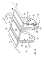
Figur 3 insgesamt mit 28 bezeichnete Abdeckteil ist insgesamt U-förmig ausgebildet und enthält ein Oberteil 32, von dem nach unten zwei Schenkel 34, 36 vorstehen. Das Abdeckteil 28 ist an seitlichen Führungs- bzw. Halteteilen 38 und 40 mittels Lagerzapfen 42 und 44 um eine in Fahrzeugquerrichtung gerichtete Achse B-B schwenkbar gelagert. In jeweils neben den Schenkeln 34 und 36 angeordneten Schenkeln der Halteteile 38 und 40 sind Führungsnuten 46 ausgebildet, die konzentrisch zur Schwenkachse B-B verlaufen und in denen Führungszapfen 48 beweglich sind, die an den Schenkeln 34 und 36 des Abdeckteils 28 vorgesehen sind. InFigur 3 ist jeweils nur eine Führungsnute und ein Führungszapfen sichtbar. - Eine Schenkelfeder 50 stützt sich mit einem Schenkel an dem Halteteil und mit dem anderen Schenkel an dem Führungszapfen 48 ab und spannt das Abdeckteil 28 elastisch in seine in
Figur 3 dargestellte Schließstellung vor, die bspw. durch den Anschlag des Führungszapfen 48 am Ende der Führungsnute 46 definiert ist. Es versteht sich, dass an beiden Halteteilen 38, 40 Vorspannfedern vorgesehen sein können. - In
Figur 3 gestrichelt eingezeichnet ist das Verkleidungsteil 24 mit der Durchgangsöffnung 26. - Das Oberteil 32 des Abdeckteils 28 ist mit einem vorstehenden mittleren Bereich 52 ausgebildet, dessen Oberseite in der in
Figur 3 dargestellten Schließstellung des Abdeckteils 28 bündig mit der benachbarten Oberfläche des Verkleidungsteils 20 verläuft, so dass die Durchgangsöffnung 26 durch das Abdeckteil 28 verschlossen ist. Es versteht sich, dass die Oberfläche des Bereiches 52 vorteilhafterweise aus ähnlichen Material besteht oder ein ähnliches Aussehen hat wie die benachbarten Oberflächenbereiche des Verkleidungsteils 24. - Den mittleren Bereich 52 seitlich umgebende Bereichen 54 des Abdeckteils 28 überlappen einen Spalt zwischen dem Bereich 24 und der Durchgangsöffnung 26 und verlaufen bündig mit ihnen benachbarten Oberflächen von Randflanschen 56 und 58 der Halteteile 38 und 40, die an der Unterseite des Verkleidungsteils 20 anliegen.
- Die Halteteile 38 und 40 können an Karosserieblechen und/oder der Unterseite des Verkleidungsteils 24 befestigt sein.
- Die Funktion der beschriebenen Anordnung wird im Folgenden anhand der
Figur 4 erläutert, die eine Ansicht der Anordnung gemäßFigur 3 von rechts zeigt. Mit ausgezogenen Linien ist inFigur 4 die geschlossene Stellung des Abdeckteils 28 dargestellt. - Wenn das Verdeck geschlossen wird, gelangt das Gestängeteil 22, das sich in den Raum zwischen den Schenkeln 34 und 36 hineinbewegt, in seine Stellung gemäß 221 in Anlage an den Hinterrand des Abdeckteils 28 und verschwenkt diese bei weiterem Schließen in Uhrzeigerrichtung, so dass sich der Vorderrand des Oberteils 32 längs der Kurven a, b auf einer Kreisbahn um die Mitte des Lagerzapfens 44 unter das Verkleidungsteil 24 bewegt. Die Kurven a und b stellen die Bewegungsbahn des vorderen oberen Randes des Bereiches 52 und des Bereiches 54 dar. In geschlossener Stellung des Verdecks nimmt das Gestängeteil 22 die Stellung gemäß 222 ein, in der das Abdeckteil 28 unter zunehmender Spannung 54 in seine vollständig unterhalb des Verkleidungsteil 24 verschwenkte Stellung verschwenkt ist. Beim Öffnen des Verdecks wird das Abdeckteil 28 durch die Vorspannung der Schenkelfeder 50 in gegen Uhrzeigerrichtung verschwenkt und folgt der Bewegung des Gestängeteils 22.
- Wie aus
Figur 4 ersichtlich, befindet sich die Schwenkachse B-B (Figur 3 ), die der Mitte des Lagerzapfens 44 entspricht in Schließstellung des Abdeckteil 28 unter dem hinteren Bereich des Oberteils 32 angeordnet. Bevorzugt befindet sich der Lagerzapfen 44 gemäßFigur 4 noch weiter links, wobei er sich vollständig außerhalb und hinter dem Oberteil befinden kann. Dadurch kann ein Spaltmaß s zwischen dem Rand der Oberseite des Verkleidungsteils 24 und dem Rand der Oberseite des Abdeckteils 28 verkleinert werden. - Die beschriebene Konstruktion kann in vielfältiger Weise abgeändert werden. Bspw. können die beide Halteteile über ein unterhalb des Verkleidungsteils 24 angeordnetes Verbindungsglied starr miteinander verbunden werden, so dass eine vollständig vormontierte Baugruppe aus den Teilen gemäß
Figur 3 im Fahrzeug montiert werden kann. Die Halteteile können durch Karosseriebleche gebildet sein. Bei entsprechend stabiler Ausbildung des Lagerzapfens genügt ein seitliches Halteteil. Das Abdeckteil muß dann nicht mit zwei seitlichen Schenkeln ausgebildet sein. Wesentlich für die Realisierung der Erfindung ist, dass das Abdeckteil 28 um eine quer zur Fahrzeuglängsrichtung verlaufende Achse nach unten verschwenkbar ist. Die Verschwenkung geschieht vorteilhafterweise unmittelbar durch die Anlage des Gestängeteils. Es können jedoch auch motorische Mittel oder sonstige Antriebsvorrichtungen zum Verschwenken vorgesehen sein. Dies ist auch dann vorteilhaft, wenn das Abdeckteil in seine Offenstellung verschwenkt werden soll um bspw. Wartungsarbeiten am Verdeckgestänge vorzunehmen. -
- 10
- Cabrioletfahrzeug
- 12
- Verdeckgestänge
- 14
- Seitengestänge
- 16
- Querspriegel
- 18
- Verdeckkasten
- 20
- Verdeckklappe
- 22
- Gestängeteil
- 24
- Verkleidungsteil
- 26
- Durchgangsöffnung
- 28
- Abdeckteil
- 30
- Spannbügel
- 32
- Oberteil
- 34
- Schenkel
- 36
- Schenkel
- 38
- Halteteil
- 40
- Halteteil
- 42
- Lagerzapfen
- 44
- Lagerzapfen
- 46
- Führungsnuten
- 48
- Führungszapfen
- 50
- Schenkelfeder
- 52
- Bereich
- 54
- Bereich
- 56
- Randflansch
- 58
- Randflansch
Claims (6)
- Abdeckvorrichtung für eine in einem oberen, hinteren Seitenwandbereich eines Cabrioletfahrzeugs angeordnete Durchgangsöffnung (26), durch welche sich beim Öffnen und Schließen des Verdecks wenigstens ein Gestängeteil (22) eines seitlichen Verdeckgestänges hindurchbewegt, welche Abdeckvorrichtung ein Abdeckteil (28) enthält, das beim Schließen des Verdecks aus einer die Durchgangsöffnung verschließenden Schließstellung in eine die Durchgangsöffnung freigebende Öffnungsstellung bewegbar ist, wobei das.Abdeckteil (28) ein die Durchgangsöffnung (26) in Schließstellung verschließendes Oberteil (32) aufweist, das starr mit wenigstens einem Schenkel (34, 36) verbunden ist, der um eine fahrzeugfeste Schwenkachse (B) schwenkbar gelagert ist, die bei in Schließstellung befindlichen Abdeckteil unterhalb von dessen Oberteil verläuft, dadurch gekennzeichnet, dass die fahrzeugfeste Schwenkachse (B) in Fahrzeugquerrichtung verläuft, wobei das Abdeckteil (28) beim Schließen des Verdecks durch das Gestängeteil (22) nach vorne verschwenkt wird.
- Vorrichtung nach Anspruch 1, dadurch gekennzeichnet, dass die Schwenkachse (B) bezogen auf die Fahrzeuglängsrichtung hinter einem vorderen Rand des Abdeckteils (28) angeordnet ist.
- Vorrichtung nach einem der Ansprüche 1 oder 2,
dadurch gekennzeichnet, dass das Abdeckteil (28) elastisch in seine Schließstellung vorgespannt ist - Vorrichtung nach einem der Ansprüche 1 bis 3,
dadurch gekennzeichnet, dass das Abdeckteil (28) insgesamt U-förmig ist, wobei die Schenkel (34, 36) des U im Bereich ihrer freien Enden um eine gemeinsame fahrzeugfeste Schwenkachsen (B) schwenkbar gelagert sind. - Vorrichtung nach einem der Ansprüche 1 bis 4,
dadurch gekennzeichnet, dass der bzw. die Schenkel (34, 36) an einem fahrzeugfesten Halteteil (38, 40) schwenkbar gelagert ist bzw. sind. - Vorrichtung nach Anspruch 5, dadurch gekennzeichnet, dass die Durchgangsöffnung (26) in einem fahrzeugfesten Verkleidungsteil (24) ausgebildet ist und das Oberteil (32) des Abdeckteils (28) die Durchgangsöffnung in Schließstellung überlappende Seitenbereiche (54) und einen vorstehenden mittleren Bereich (52) aufweist, dessen Oberseite bündig mit den benachbarten Bereichen der Oberseite des Verkleidungsteils (24) verläuft.
Applications Claiming Priority (2)
| Application Number | Priority Date | Filing Date | Title |
|---|---|---|---|
| DE202004009799U | 2004-06-22 | ||
| DE200420009799 DE202004009799U1 (de) | 2004-06-22 | 2004-06-22 | Abdeckvorrichtung für eine in einem oberen, hinteren Seitenwandbereich eines Cabrioletfahrzeuges angeordnete Durchgangsöffnung |
Publications (3)
| Publication Number | Publication Date |
|---|---|
| EP1609651A2 EP1609651A2 (de) | 2005-12-28 |
| EP1609651A3 EP1609651A3 (de) | 2006-03-08 |
| EP1609651B1 true EP1609651B1 (de) | 2014-04-30 |
Family
ID=32981588
Family Applications (1)
| Application Number | Title | Priority Date | Filing Date |
|---|---|---|---|
| EP05013402.2A Expired - Lifetime EP1609651B1 (de) | 2004-06-22 | 2005-06-22 | Abdeckvorrichtung für eine in einem oberen, hinteren Seitenwandbereich eines Cabrioletfahrzeuges angeordnete Durchgangsöffnung |
Country Status (2)
| Country | Link |
|---|---|
| EP (1) | EP1609651B1 (de) |
| DE (1) | DE202004009799U1 (de) |
Families Citing this family (6)
| Publication number | Priority date | Publication date | Assignee | Title |
|---|---|---|---|---|
| DE102005043265A1 (de) * | 2005-09-09 | 2007-03-15 | Wilhelm Karmann Gmbh | Vorrichtung zur Abdeckung einer Gestängedurchtrittsöffnung eines Cabrioletfahrzeugs und Cabrioletfahrzeug mit einer solchen Vorrichtung |
| DE102006012559A1 (de) * | 2006-03-16 | 2007-09-20 | Wilhelm Karmann Gmbh | Gestängeklappe für ein Cabriolet-Fahrzeug und Cabriolet-Fahrzeug mit einer Gestängeklappe |
| DE102006030522B3 (de) | 2006-07-01 | 2007-08-16 | Dr.Ing.H.C. F. Porsche Ag | Fahrzeugwand |
| DE102007027859B4 (de) * | 2007-06-13 | 2015-05-07 | Webasto-Edscha Cabrio GmbH | Abdeckung für eine Gestängeaustrittsöffnung |
| DE102009004047B4 (de) * | 2009-01-08 | 2019-09-26 | Dr. Ing. H.C. F. Porsche Aktiengesellschaft | Gestängeklappe für einen Aufbau eines Personenkraftwagens |
| DE102012106970B4 (de) * | 2012-07-31 | 2024-04-11 | Dr. Ing. H.C. F. Porsche Aktiengesellschaft | Kraftfahrzeug mit einem ablegbaren Verdeck |
Citations (1)
| Publication number | Priority date | Publication date | Assignee | Title |
|---|---|---|---|---|
| DE10143365A1 (de) * | 2001-09-04 | 2003-03-27 | Webasto Vehicle Sys Int Gmbh | Abdeckklappe für ein Fahrzeug |
Family Cites Families (5)
| Publication number | Priority date | Publication date | Assignee | Title |
|---|---|---|---|---|
| US4687247A (en) * | 1985-05-13 | 1987-08-18 | Muscat Peter P | Powered tonneau cover for convertible automobiles |
| DE3801148C1 (de) * | 1988-01-16 | 1989-04-20 | Daimler Benz Ag | Abdeckplatte für eine oberhalb eines Verdecklagers befindliche Durchlassöffnung in einer Bordwand eines Fahrzeuges |
| DE3903679C1 (de) | 1989-02-08 | 1990-04-19 | Daimler Benz Ag | Abdeckplatte für eine sich oberhalb einer Verdecklagerstelle befindende Durchlassöffnung in einer Bordwand eines Fahrzeugs |
| FR2802477B1 (fr) | 1999-12-20 | 2002-03-01 | France Design | Obturateurs lateraux et plage arriere basculants pour passage d'un toit escamotable |
| DE10142550C2 (de) | 2001-08-30 | 2003-09-11 | Karmann Gmbh W | Cabriolet-Fahrzeug |
-
2004
- 2004-06-22 DE DE200420009799 patent/DE202004009799U1/de not_active Expired - Lifetime
-
2005
- 2005-06-22 EP EP05013402.2A patent/EP1609651B1/de not_active Expired - Lifetime
Patent Citations (1)
| Publication number | Priority date | Publication date | Assignee | Title |
|---|---|---|---|---|
| DE10143365A1 (de) * | 2001-09-04 | 2003-03-27 | Webasto Vehicle Sys Int Gmbh | Abdeckklappe für ein Fahrzeug |
Also Published As
| Publication number | Publication date |
|---|---|
| DE202004009799U1 (de) | 2004-09-09 |
| EP1609651A3 (de) | 2006-03-08 |
| EP1609651A2 (de) | 2005-12-28 |
Similar Documents
| Publication | Publication Date | Title |
|---|---|---|
| DE19714105C2 (de) | Umwandelbares Fahrzeugdach | |
| DE10222189B4 (de) | Abdeckvorrichtung für einen Verdeckkasten eines Cabriolet-Fahrzeugs | |
| DE102005030203A1 (de) | Luftleitvorrichtung für ein Fahrzeug | |
| DE102008057880B4 (de) | Vorrichtung zur Verstellung einer Klappe für ein Kraftfahrzeug | |
| EP1338455B1 (de) | Windabweiseranordnung für ein öffnungsfähiges Fahrzeugdach | |
| DE10144583A1 (de) | Verdeck für ein Cabrioletfahrzeug | |
| EP1971501B1 (de) | Klappverdeck für einen kraftwagen | |
| DE102004023056A1 (de) | Klappverdeck für ein Kraftfahrzeug | |
| DE102009050064A1 (de) | Verkleidungsanordnung für einen Schwenkarm einer Kraftwagentür | |
| DE102018117521B4 (de) | Fahrzeugaufbau mit starrem Verdeckelement und öffenbarer Heckscheibe | |
| EP1897718B1 (de) | Faltverdeck | |
| DE102013007876A1 (de) | Fahrzeugtüranordnung | |
| EP1193094A2 (de) | Mechanik für einen Windabweiser eines öffnungsfähigen Fahrzeugdachs | |
| EP1609651A2 (de) | Abdeckvorrichtung für eine in einem oberen, hinteren Seitenwandbereich eines Cabrioletfahrzeuges angeordnete Durchgangsöffnung | |
| EP1764248B1 (de) | Heckklappenanordnung mit einer kombinierten translatorisch-rotatorischen Kinematik | |
| DE102007004180B4 (de) | Verstellbares Fahrzeugdach | |
| DE102012106970B4 (de) | Kraftfahrzeug mit einem ablegbaren Verdeck | |
| DE102006055268A1 (de) | Cabriolet-Fahrzeug mit einer eine Aussparung für Verdeckgestängeteile verschließenden Abdeckklappe | |
| DE19714106C2 (de) | Umwandelbares Fahrzeugdach | |
| DE102007015705A1 (de) | Verdeck für ein Kraftfahrzeug, insbesondere Cabriolet-Fahrzeug, mit einem faltbaren Dach | |
| EP1609652B1 (de) | Verdeck für ein Cabriolet-Fahrzeug | |
| EP3242807B1 (de) | Dach für einen kraftwagen, insbesondere einen personenkraftwagen | |
| DE102004056121B4 (de) | Verdeck für ein Kraftfahrzeug | |
| DE102020100681A1 (de) | Heckklappenanordnung für ein Kraftfahrzeug und damit versehenes Kraftfahrzeug | |
| DE102007056574A1 (de) | Fahrzeug mit einem Klappverdeck |
Legal Events
| Date | Code | Title | Description |
|---|---|---|---|
| PUAI | Public reference made under article 153(3) epc to a published international application that has entered the european phase |
Free format text: ORIGINAL CODE: 0009012 |
|
| AK | Designated contracting states |
Kind code of ref document: A2 Designated state(s): AT BE BG CH CY CZ DE DK EE ES FI FR GB GR HU IE IS IT LI LT LU MC NL PL PT RO SE SI SK TR |
|
| AX | Request for extension of the european patent |
Extension state: AL BA HR LV MK YU |
|
| PUAL | Search report despatched |
Free format text: ORIGINAL CODE: 0009013 |
|
| AK | Designated contracting states |
Kind code of ref document: A3 Designated state(s): AT BE BG CH CY CZ DE DK EE ES FI FR GB GR HU IE IS IT LI LT LU MC NL PL PT RO SE SI SK TR |
|
| AX | Request for extension of the european patent |
Extension state: AL BA HR LV MK YU |
|
| 17P | Request for examination filed |
Effective date: 20060327 |
|
| AKX | Designation fees paid |
Designated state(s): AT BE BG CH CY CZ DE DK EE ES FI FR GB GR HU IE IS IT LI LT LU MC NL PL PT RO SE SI SK TR |
|
| 19U | Interruption of proceedings before grant |
Effective date: 20090629 |
|
| 19W | Proceedings resumed before grant after interruption of proceedings |
Effective date: 20101201 |
|
| 17Q | First examination report despatched |
Effective date: 20130416 |
|
| GRAP | Despatch of communication of intention to grant a patent |
Free format text: ORIGINAL CODE: EPIDOSNIGR1 |
|
| INTG | Intention to grant announced |
Effective date: 20131106 |
|
| RAP1 | Party data changed (applicant data changed or rights of an application transferred) |
Owner name: VALMET AUTOMOTIVE OY |
|
| GRAS | Grant fee paid |
Free format text: ORIGINAL CODE: EPIDOSNIGR3 |
|
| GRAA | (expected) grant |
Free format text: ORIGINAL CODE: 0009210 |
|
| AK | Designated contracting states |
Kind code of ref document: B1 Designated state(s): AT BE BG CH CY CZ DE DK EE ES FI FR GB GR HU IE IS IT LI LT LU MC NL PL PT RO SE SI SK TR |
|
| REG | Reference to a national code |
Ref country code: GB Ref legal event code: FG4D Free format text: NOT ENGLISH Ref country code: CH Ref legal event code: EP |
|
| REG | Reference to a national code |
Ref country code: AT Ref legal event code: REF Ref document number: 664862 Country of ref document: AT Kind code of ref document: T Effective date: 20140515 |
|
| REG | Reference to a national code |
Ref country code: IE Ref legal event code: FG4D Free format text: LANGUAGE OF EP DOCUMENT: GERMAN |
|
| REG | Reference to a national code |
Ref country code: DE Ref legal event code: R096 Ref document number: 502005014319 Country of ref document: DE Effective date: 20140612 |
|
| REG | Reference to a national code |
Ref country code: LT Ref legal event code: MG4D |
|
| REG | Reference to a national code |
Ref country code: NL Ref legal event code: VDEP Effective date: 20140430 |
|
| PG25 | Lapsed in a contracting state [announced via postgrant information from national office to epo] |
Ref country code: LT Free format text: LAPSE BECAUSE OF FAILURE TO SUBMIT A TRANSLATION OF THE DESCRIPTION OR TO PAY THE FEE WITHIN THE PRESCRIBED TIME-LIMIT Effective date: 20140430 Ref country code: FI Free format text: LAPSE BECAUSE OF FAILURE TO SUBMIT A TRANSLATION OF THE DESCRIPTION OR TO PAY THE FEE WITHIN THE PRESCRIBED TIME-LIMIT Effective date: 20140430 Ref country code: NL Free format text: LAPSE BECAUSE OF FAILURE TO SUBMIT A TRANSLATION OF THE DESCRIPTION OR TO PAY THE FEE WITHIN THE PRESCRIBED TIME-LIMIT Effective date: 20140430 Ref country code: CY Free format text: LAPSE BECAUSE OF FAILURE TO SUBMIT A TRANSLATION OF THE DESCRIPTION OR TO PAY THE FEE WITHIN THE PRESCRIBED TIME-LIMIT Effective date: 20140430 Ref country code: IS Free format text: LAPSE BECAUSE OF FAILURE TO SUBMIT A TRANSLATION OF THE DESCRIPTION OR TO PAY THE FEE WITHIN THE PRESCRIBED TIME-LIMIT Effective date: 20140830 Ref country code: BG Free format text: LAPSE BECAUSE OF FAILURE TO SUBMIT A TRANSLATION OF THE DESCRIPTION OR TO PAY THE FEE WITHIN THE PRESCRIBED TIME-LIMIT Effective date: 20140730 Ref country code: GR Free format text: LAPSE BECAUSE OF FAILURE TO SUBMIT A TRANSLATION OF THE DESCRIPTION OR TO PAY THE FEE WITHIN THE PRESCRIBED TIME-LIMIT Effective date: 20140731 |
|
| PG25 | Lapsed in a contracting state [announced via postgrant information from national office to epo] |
Ref country code: SE Free format text: LAPSE BECAUSE OF FAILURE TO SUBMIT A TRANSLATION OF THE DESCRIPTION OR TO PAY THE FEE WITHIN THE PRESCRIBED TIME-LIMIT Effective date: 20140430 Ref country code: PL Free format text: LAPSE BECAUSE OF FAILURE TO SUBMIT A TRANSLATION OF THE DESCRIPTION OR TO PAY THE FEE WITHIN THE PRESCRIBED TIME-LIMIT Effective date: 20140430 Ref country code: ES Free format text: LAPSE BECAUSE OF FAILURE TO SUBMIT A TRANSLATION OF THE DESCRIPTION OR TO PAY THE FEE WITHIN THE PRESCRIBED TIME-LIMIT Effective date: 20140430 |
|
| PG25 | Lapsed in a contracting state [announced via postgrant information from national office to epo] |
Ref country code: PT Free format text: LAPSE BECAUSE OF FAILURE TO SUBMIT A TRANSLATION OF THE DESCRIPTION OR TO PAY THE FEE WITHIN THE PRESCRIBED TIME-LIMIT Effective date: 20140901 |
|
| PG25 | Lapsed in a contracting state [announced via postgrant information from national office to epo] |
Ref country code: CZ Free format text: LAPSE BECAUSE OF FAILURE TO SUBMIT A TRANSLATION OF THE DESCRIPTION OR TO PAY THE FEE WITHIN THE PRESCRIBED TIME-LIMIT Effective date: 20140430 Ref country code: EE Free format text: LAPSE BECAUSE OF FAILURE TO SUBMIT A TRANSLATION OF THE DESCRIPTION OR TO PAY THE FEE WITHIN THE PRESCRIBED TIME-LIMIT Effective date: 20140430 Ref country code: MC Free format text: LAPSE BECAUSE OF FAILURE TO SUBMIT A TRANSLATION OF THE DESCRIPTION OR TO PAY THE FEE WITHIN THE PRESCRIBED TIME-LIMIT Effective date: 20140430 Ref country code: LU Free format text: LAPSE BECAUSE OF FAILURE TO SUBMIT A TRANSLATION OF THE DESCRIPTION OR TO PAY THE FEE WITHIN THE PRESCRIBED TIME-LIMIT Effective date: 20140622 Ref country code: SK Free format text: LAPSE BECAUSE OF FAILURE TO SUBMIT A TRANSLATION OF THE DESCRIPTION OR TO PAY THE FEE WITHIN THE PRESCRIBED TIME-LIMIT Effective date: 20140430 Ref country code: RO Free format text: LAPSE BECAUSE OF FAILURE TO SUBMIT A TRANSLATION OF THE DESCRIPTION OR TO PAY THE FEE WITHIN THE PRESCRIBED TIME-LIMIT Effective date: 20140430 Ref country code: DK Free format text: LAPSE BECAUSE OF FAILURE TO SUBMIT A TRANSLATION OF THE DESCRIPTION OR TO PAY THE FEE WITHIN THE PRESCRIBED TIME-LIMIT Effective date: 20140430 |
|
| PGFP | Annual fee paid to national office [announced via postgrant information from national office to epo] |
Ref country code: DE Payment date: 20141024 Year of fee payment: 10 Ref country code: FR Payment date: 20141021 Year of fee payment: 10 |
|
| REG | Reference to a national code |
Ref country code: CH Ref legal event code: PL |
|
| REG | Reference to a national code |
Ref country code: DE Ref legal event code: R097 Ref document number: 502005014319 Country of ref document: DE |
|
| PLBE | No opposition filed within time limit |
Free format text: ORIGINAL CODE: 0009261 |
|
| STAA | Information on the status of an ep patent application or granted ep patent |
Free format text: STATUS: NO OPPOSITION FILED WITHIN TIME LIMIT |
|
| GBPC | Gb: european patent ceased through non-payment of renewal fee |
Effective date: 20140730 |
|
| REG | Reference to a national code |
Ref country code: IE Ref legal event code: MM4A |
|
| PG25 | Lapsed in a contracting state [announced via postgrant information from national office to epo] |
Ref country code: IT Free format text: LAPSE BECAUSE OF FAILURE TO SUBMIT A TRANSLATION OF THE DESCRIPTION OR TO PAY THE FEE WITHIN THE PRESCRIBED TIME-LIMIT Effective date: 20140430 |
|
| 26N | No opposition filed |
Effective date: 20150202 |
|
| PG25 | Lapsed in a contracting state [announced via postgrant information from national office to epo] |
Ref country code: LI Free format text: LAPSE BECAUSE OF NON-PAYMENT OF DUE FEES Effective date: 20140630 Ref country code: CH Free format text: LAPSE BECAUSE OF NON-PAYMENT OF DUE FEES Effective date: 20140630 Ref country code: IE Free format text: LAPSE BECAUSE OF NON-PAYMENT OF DUE FEES Effective date: 20140622 |
|
| REG | Reference to a national code |
Ref country code: DE Ref legal event code: R097 Ref document number: 502005014319 Country of ref document: DE Effective date: 20150202 |
|
| PG25 | Lapsed in a contracting state [announced via postgrant information from national office to epo] |
Ref country code: GB Free format text: LAPSE BECAUSE OF NON-PAYMENT OF DUE FEES Effective date: 20140730 |
|
| PG25 | Lapsed in a contracting state [announced via postgrant information from national office to epo] |
Ref country code: SI Free format text: LAPSE BECAUSE OF FAILURE TO SUBMIT A TRANSLATION OF THE DESCRIPTION OR TO PAY THE FEE WITHIN THE PRESCRIBED TIME-LIMIT Effective date: 20140430 |
|
| REG | Reference to a national code |
Ref country code: AT Ref legal event code: MM01 Ref document number: 664862 Country of ref document: AT Kind code of ref document: T Effective date: 20140622 |
|
| PG25 | Lapsed in a contracting state [announced via postgrant information from national office to epo] |
Ref country code: AT Free format text: LAPSE BECAUSE OF NON-PAYMENT OF DUE FEES Effective date: 20140622 |
|
| REG | Reference to a national code |
Ref country code: DE Ref legal event code: R119 Ref document number: 502005014319 Country of ref document: DE |
|
| REG | Reference to a national code |
Ref country code: FR Ref legal event code: ST Effective date: 20160229 |
|
| PG25 | Lapsed in a contracting state [announced via postgrant information from national office to epo] |
Ref country code: DE Free format text: LAPSE BECAUSE OF NON-PAYMENT OF DUE FEES Effective date: 20160101 |
|
| PG25 | Lapsed in a contracting state [announced via postgrant information from national office to epo] |
Ref country code: FR Free format text: LAPSE BECAUSE OF NON-PAYMENT OF DUE FEES Effective date: 20150630 |
|
| PG25 | Lapsed in a contracting state [announced via postgrant information from national office to epo] |
Ref country code: BE Free format text: LAPSE BECAUSE OF FAILURE TO SUBMIT A TRANSLATION OF THE DESCRIPTION OR TO PAY THE FEE WITHIN THE PRESCRIBED TIME-LIMIT Effective date: 20140630 Ref country code: HU Free format text: LAPSE BECAUSE OF FAILURE TO SUBMIT A TRANSLATION OF THE DESCRIPTION OR TO PAY THE FEE WITHIN THE PRESCRIBED TIME-LIMIT; INVALID AB INITIO Effective date: 20050622 Ref country code: TR Free format text: LAPSE BECAUSE OF FAILURE TO SUBMIT A TRANSLATION OF THE DESCRIPTION OR TO PAY THE FEE WITHIN THE PRESCRIBED TIME-LIMIT Effective date: 20140430 |