EP1609334B1 - Ultrasonic energy system and method including a ceramic horn - Google Patents
Ultrasonic energy system and method including a ceramic horn Download PDFInfo
- Publication number
- EP1609334B1 EP1609334B1 EP04716164.1A EP04716164A EP1609334B1 EP 1609334 B1 EP1609334 B1 EP 1609334B1 EP 04716164 A EP04716164 A EP 04716164A EP 1609334 B1 EP1609334 B1 EP 1609334B1
- Authority
- EP
- European Patent Office
- Prior art keywords
- horn
- waveguide
- ultrasonic energy
- molten metal
- fluid medium
- Prior art date
- Legal status (The legal status is an assumption and is not a legal conclusion. Google has not performed a legal analysis and makes no representation as to the accuracy of the status listed.)
- Expired - Lifetime
Links
Images


Classifications
-
- H—ELECTRICITY
- H04—ELECTRIC COMMUNICATION TECHNIQUE
- H04R—LOUDSPEAKERS, MICROPHONES, GRAMOPHONE PICK-UPS OR LIKE ACOUSTIC ELECTROMECHANICAL TRANSDUCERS; DEAF-AID SETS; PUBLIC ADDRESS SYSTEMS
- H04R17/00—Piezoelectric transducers; Electrostrictive transducers
-
- B—PERFORMING OPERATIONS; TRANSPORTING
- B01—PHYSICAL OR CHEMICAL PROCESSES OR APPARATUS IN GENERAL
- B01J—CHEMICAL OR PHYSICAL PROCESSES, e.g. CATALYSIS OR COLLOID CHEMISTRY; THEIR RELEVANT APPARATUS
- B01J19/00—Chemical, physical or physico-chemical processes in general; Their relevant apparatus
- B01J19/08—Processes employing the direct application of electric or wave energy, or particle radiation; Apparatus therefor
- B01J19/10—Processes employing the direct application of electric or wave energy, or particle radiation; Apparatus therefor employing sonic or ultrasonic vibrations
-
- B—PERFORMING OPERATIONS; TRANSPORTING
- B06—GENERATING OR TRANSMITTING MECHANICAL VIBRATIONS IN GENERAL
- B06B—METHODS OR APPARATUS FOR GENERATING OR TRANSMITTING MECHANICAL VIBRATIONS OF INFRASONIC, SONIC, OR ULTRASONIC FREQUENCY, e.g. FOR PERFORMING MECHANICAL WORK IN GENERAL
- B06B1/00—Methods or apparatus for generating mechanical vibrations of infrasonic, sonic, or ultrasonic frequency
- B06B1/02—Methods or apparatus for generating mechanical vibrations of infrasonic, sonic, or ultrasonic frequency making use of electrical energy
- B06B1/06—Methods or apparatus for generating mechanical vibrations of infrasonic, sonic, or ultrasonic frequency making use of electrical energy operating with piezoelectric effect or with electrostriction
-
- B—PERFORMING OPERATIONS; TRANSPORTING
- B06—GENERATING OR TRANSMITTING MECHANICAL VIBRATIONS IN GENERAL
- B06B—METHODS OR APPARATUS FOR GENERATING OR TRANSMITTING MECHANICAL VIBRATIONS OF INFRASONIC, SONIC, OR ULTRASONIC FREQUENCY, e.g. FOR PERFORMING MECHANICAL WORK IN GENERAL
- B06B3/00—Methods or apparatus specially adapted for transmitting mechanical vibrations of infrasonic, sonic, or ultrasonic frequency
-
- B—PERFORMING OPERATIONS; TRANSPORTING
- B21—MECHANICAL METAL-WORKING WITHOUT ESSENTIALLY REMOVING MATERIAL; PUNCHING METAL
- B21C—MANUFACTURE OF METAL SHEETS, WIRE, RODS, TUBES, PROFILES OR LIKE SEMI-MANUFACTURED PRODUCTS OTHERWISE THAN BY ROLLING; AUXILIARY OPERATIONS USED IN CONNECTION WITH METAL-WORKING WITHOUT ESSENTIALLY REMOVING MATERIAL
- B21C1/00—Manufacture of metal sheets, wire, rods, tubes or like semi-manufactured products by drawing
- B21C1/006—Manufacture of metal sheets, wire, rods, tubes or like semi-manufactured products by drawing using vibratory energy
-
- B—PERFORMING OPERATIONS; TRANSPORTING
- B21—MECHANICAL METAL-WORKING WITHOUT ESSENTIALLY REMOVING MATERIAL; PUNCHING METAL
- B21C—MANUFACTURE OF METAL SHEETS, WIRE, RODS, TUBES, PROFILES OR LIKE SEMI-MANUFACTURED PRODUCTS OTHERWISE THAN BY ROLLING; AUXILIARY OPERATIONS USED IN CONNECTION WITH METAL-WORKING WITHOUT ESSENTIALLY REMOVING MATERIAL
- B21C37/00—Manufacture of metal sheets, rods, wire, tubes, profiles or like semi-manufactured products, not otherwise provided for; Manufacture of tubes of special shape
- B21C37/04—Manufacture of metal sheets, rods, wire, tubes, profiles or like semi-manufactured products, not otherwise provided for; Manufacture of tubes of special shape of rods or wire
- B21C37/042—Manufacture of coated wire or rods
-
- B—PERFORMING OPERATIONS; TRANSPORTING
- B22—CASTING; POWDER METALLURGY
- B22D—CASTING OF METALS; CASTING OF OTHER SUBSTANCES BY THE SAME PROCESSES OR DEVICES
- B22D19/00—Casting in, on, or around objects which form part of the product
- B22D19/14—Casting in, on, or around objects which form part of the product the objects being filamentary or particulate in form
-
- C—CHEMISTRY; METALLURGY
- C22—METALLURGY; FERROUS OR NON-FERROUS ALLOYS; TREATMENT OF ALLOYS OR NON-FERROUS METALS
- C22C—ALLOYS
- C22C47/00—Making alloys containing metallic or non-metallic fibres or filaments
- C22C47/08—Making alloys containing metallic or non-metallic fibres or filaments by contacting the fibres or filaments with molten metal, e.g. by infiltrating the fibres or filaments placed in a mould
-
- H—ELECTRICITY
- H04—ELECTRIC COMMUNICATION TECHNIQUE
- H04R—LOUDSPEAKERS, MICROPHONES, GRAMOPHONE PICK-UPS OR LIKE ACOUSTIC ELECTROMECHANICAL TRANSDUCERS; DEAF-AID SETS; PUBLIC ADDRESS SYSTEMS
- H04R19/00—Electrostatic transducers
-
- B—PERFORMING OPERATIONS; TRANSPORTING
- B22—CASTING; POWDER METALLURGY
- B22F—WORKING METALLIC POWDER; MANUFACTURE OF ARTICLES FROM METALLIC POWDER; MAKING METALLIC POWDER; APPARATUS OR DEVICES SPECIALLY ADAPTED FOR METALLIC POWDER
- B22F2999/00—Aspects linked to processes or compositions used in powder metallurgy
Definitions
- the present invention relates to acoustics. More particularly, it relates to an ultrasonic system and method incorporating a ceramic horn for long-term delivery of ultrasonic energy in harsh environments, such as high temperature and/or corrosive environments.
- Ultrasonic is the science of the effects of sound vibrations beyond the limit of audible frequencies.
- the object of high-powered ultrasonic applications is to bring about some physical change in the material being treated. This process requires the flow of vibratory energy per unit of area or volume. Depending upon the application, the resulting power density may range from less than a watt to thousands of watts per square centimeter.
- ultrasonics is used in a wide variety of applications, such as welding or cutting of materials.
- the ultrasonic device or system itself generally consists of a transducer, a booster, a waveguide, and a horn. These components are often times referred to in combination as a "horn stack".
- the transducer converts electrical energy delivered by a power supply into high frequency mechanical vibration.
- the booster amplifies or adjusts the vibrational output from the transducer.
- the waveguide transfers the amplified vibration from the booster to the horn, and provides an appropriate surface for mounting of the horn.
- the waveguide component is normally employed for design purposes to reduce heat transfer to the transducer and to optimize performance of the horn stack in terms of acoustics and handling.
- the waveguide is not a required component and is not always employed. Instead, the horn is often times directly connected to the booster.
- the horn is an acoustical tool usually having a length of a multiple of one-half of the horn material wavelength and is normally comprised, for example, of aluminum, titanium, or steel that transfers the mechanical vibratory energy to the desired application point.
- Horn displacement or amplitude is the peak-to-peak movement of the horn face.
- the ratio of horn output amplitude to the horn input amplitude is termed "gain".
- Gain is a function of the ratio of the mass of the horn at the vibration input and output sections.
- the direction of amplitude at the face of the horn is coincident with the direction of the applied mechanical vibrations.
- the horn can assume a variety of shapes, including simple cylindrical, spool, bell, block, bar, etc. Further, the leading portion (or “tip") of the horn can have a size and/or shape differing form a remainder of the horn body. In certain configurations, the horn tip can be a replaceable component. As used throughout this specification, the term "horn" is inclusive of both uniformly shaped horns as well as horn structures that define an identifiable horn tip. Finally, for certain applications such as ultrasonic cutting and welding, an additional anvil component is provided. Regardless, however, ultrasonic horn configuration and material composition is relatively standard.
- accepted horn materials of aluminum, titanium, and steel are highly viable, with the primary material selection criteria being the desired operational frequency.
- the material to which the ultrasonic energy is applied is at room temperature and relatively inert, such that horn wear, if any, is minimal.
- wear concerns may arise.
- the horn operates in an intense environment (e.g., corrosive and/or high temperature)
- accepted horn materials may not provide acceptable results.
- ultrasonic energy is commonly employed to effectuate infiltration of a fluid medium into a working part.
- Fabrication of fiber reinforced metal matrix composite wires are one such example whereby a tow of fibers are immersed in a molten metal (e.g., aluminum-based molten metal). Acoustic waves are introduced into the molten metal (via an ultrasonic horn immersed therein), causing the molten metal to infiltrate the fiber tow, thus producing the metal matrix composite wire.
- a molten metal e.g., aluminum-based molten metal
- Acoustic waves are introduced into the molten metal (via an ultrasonic horn immersed therein), causing the molten metal to infiltrate the fiber tow, thus producing the metal matrix composite wire.
- the molten aluminum represents an extremely harsh environment, as it is both intensely hot (on the order of 700° C) and chemically corrosive. Under severe conditions, titanium and steel horns will quickly deteriorate.
- Other available metal-based horn constructions provide only nominal horn working life improvements.
- niobium-molybdenum alloys e.g., at least 4.5% molybdenum
- metal matrix composite wire manufacturers commonly employ a series of niobium-molybdenum alloys (e.g., at least 4.5% molybdenum) for the horn.
- niobium-based horns provide a limited working life in molten aluminum before re-machining is required.
- niobium alloy horns become unstable, potentially creating unexpected processing problems.
- formation of the niobium-molybdenum alloy horns entails precise, lengthy and expensive casting, hot working, and final machining operations. In view of the high cost of these and other materials, niobium (and its alloys) and other accepted horn materials are less than optimal for harsh environment ultrasonic applications.
- US 4 649 060 is directed to a method of producing a preform wire, sheet or tape fibre reinforced metal composite.
- the method comprises unfastening and drawing a silicon carbide fibre bundle such that the element fibres constituting the fibre bundle are uniformly arranged in a parallel relation along their length direction, and impregnating the fibre bundle for a period of time of no longer than 50 seconds with a molten metal, while ultrasonically vibrating the fibre bundle (see claim 1).
- Molten metal is vibrated by means of an ultrasonic wave vibration apparatus comprising an oscillator and a vibrator. The lower portion of a horn of the vibrator is immersed in the molten metal filled in a vessel (see column 4, lines 18-23).
- Ultrasonic devices are beneficially used in a number of applications.
- the ultrasonic system of the present invention facilitates long-term operation in extreme environments such as high temperature and/or corrosive fluid mediums.
- ceramic-based horns such as SiN 4 , sialon, Al 2 O 3 , SiC, TiB 2 , etc., have virtually no chemical reactivity when applying vibratory energy to highly corrosive and molten metal media, especially molten aluminum.
- the fluid medium is corrosive and has a temperature of at least 500° C, and the method is characterized by not replacing the horn for at least 100 hours of ultrasonic energy delivery.
- Yet another aspect of the present invention relates to a method according to claim 11.
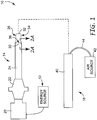
- the ultrasonic system 10 includes an energy source 12 (shown in block form), an ultrasonic or horn stack 14, and a cooling system 16. Details on the various components are described below.
- the horn stack 14 includes a transducer 20, a booster 22, a waveguide 24, and a horn 26. At least a portion of the horn 26 is comprised of a ceramic material and is adapted to deliver mechanical vibratory energy generated by the transducer 20, the booster 22, and the waveguide 24 via input from the energy source 12.
- the energy source 12, the transducer 20, and the booster 22 are generally conventional components, and can assume a variety of forms.
- the energy source 12 is configured to provide high frequency electrical energy to the transducer 20.
- the transducer 20 converts electricity from the energy source 12 to mechanical vibration, nominally 20 kHz.
- the transducer 20 in accordance with the present invention can thus be any available type such as piezoelectric, electromechanical, etc.
- the booster 22 is also of a type known in the art, adapted to amplify the vibrational output from the transducer 20 and transfer the same to waveguide 24/horn 26.
- the system 10 can include the waveguide 24 between the booster 22 and the horn 26, in an alternative embodiment, the horn 26 is directly connected to the booster 22 such that the waveguide 24 is eliminated.
- the horn 26, and where provided the waveguide 24, represent distinct improvements over known ultrasonic systems.
- a substantial portion of the horn 26, and in one embodiment an entirety of the horn 26, is formed of a ceramic material.
- the horn 26 is defined by a trailing end 30 and a leading end 32.
- the trailing end 30 is attached to the waveguide 24, whereas the leading end 32 represents the working end of the horn 26.
- the leading end 32 (along with portions of the horn 26 adjacent the leading end 32), is immersed in the fluid medium.
- the horn 26 is defined by a length from the trailing end 30 to the leading end 32, and defines a horn material wavelength.
- the ceramic portion of the horn 26 is at least 1/8 of this wavelength in length, extending proximally from the leading end 32 toward the trailing end 30.
- the horn 26 defines a ceramic leading section 34 having a length of at least 1/8 the horn material wavelength.
- the ceramic portion leading section 34 can have a length that is greater than 1/8 the horn material wavelength, for example at least 1 ⁇ 4 wavelength or 1 ⁇ 2 wavelength.
- an entirety of the horn 26 is formed of a ceramic material.
- the ceramic portion of the horn is not a mere coating or small head piece; instead, the present invention utilizes ceramic along a significant portion of the horn 26.
- the ceramic portion of the horn 26 can be silicon nitride, aluminum oxide, titanium diboride, zirconia, silicon carbide, etc.
- the ceramic portion of the horn 26 is an alumina, silicon nitride ceramic composite, such as sialon (Si 6-x Al x O x N 8-x ).
- the horn 26 is depicted in FIG. 1 as being a cylindrical rod, other shapes are available.
- the horn 26 can be a rectangular- or square-shaped (in cross-section) bar, spherical, tapered, double tapered, etc.
- the selected shape of the horn 26 is a function of the intended end application.
- the waveguide 24 can assume a variety of forms, as can the coupling therebetween.
- a trailing section 36 of the horn 26 is something other than ceramic (e.g., titanium, niobium, or other conventional horn material)
- the waveguide 24 can also be of a known configuration, as can the technique by which the horn 26 is secured to the waveguide 24.
- the trailing section 36 of the horn 26 is comprised of a standard horn material, such as niobium and its alloys
- the waveguide 24 can be formed of a titanium and/or steel material, and the horn 26 mounted thereto with a threaded fastener.
- Alternative mounting techniques not previously employed in the ultrasonic horn art are described below.
- a mechanical fit mounting technique can be employed to couple the horn 26 and the waveguide 24 (or the booster 22 when the waveguide 24 not included).
- the waveguide 24 and the horn 26 are adapted to facilitate an interference fit therebetween.
- the waveguide 24 forms an internal bore 38 having a dimension(s) corresponding with an outer dimension(s) of the horn 26.
- the bore 38 and the trailing end 30 define diameters selected to generate an appropriate interference fit therebetween.
- the ultrasonic system 10 is preferably adapted for use in high temperature environments (i.e., at least 200° C; at least 350° C in another embodiment; at least 500° C in another embodiment), such as molten metal.
- high temperature environments i.e., at least 200° C; at least 350° C in another embodiment; at least 500° C in another embodiment
- the interference or junction fit must be such that the ceramic horn 26 does not loosen relative to the waveguide 24 at the high temperatures likely encountered.
- the waveguide 24 is formed in one embodiment of a material other than ceramic to best facilitate connection between the booster 22 and the horn 26; it being recognized that by using varying materials for the waveguide 24 and the horn 26, these components will expand at different rates when subjected to highly elevated temperatures.
- the waveguide 24 is formed of a titanium material as opposed to other often employed materials for these high temperature applications (such as niobium) because the hoop stresses caused by the interference fit are much less than the yield strength of titanium. That is to say, niobium (and alloys thereof) is unable to withstand expected hoop stresses at elevated temperatures (e.g., on the order of at least 500° C).
- the waveguide 24 is preferably titanium, and the bore 40 is selected to provide an interference fit of 0.003 inch at room temperature.
- the above interference fit clamping-type technique for assembling the horn 26 to the waveguide 24 is but one acceptable approach.
- Other mechanical clamping techniques can be employed, such as forming the waveguide 24 to include a split clamp configuration, etc.
- the junction point between the waveguide 24 and the horn 26 is preferably at the anti-node of the waveguide 24, although other junction points (e.g., a vibrational node of the waveguide 24) are acceptable.
- the interference assembly technique of the horn 26 to the waveguide 24 facilitates overall tuning of the horn stack 14 by machining or adjusting of the waveguide 24. This is in contrast to accepted techniques whereby the horn 26 is precisely machined as a half-wavelength horn.
- the present invention facilitating machining the waveguide 24 as part of the tuning process.
- the horn 26 can have a length that is something other than a half-wavelength. To this end, it is recognized that typically a half-wavelength requirement is needed for both the waveguide 24 and the horn 26 lengths to maintain nodes at a mid-span of the waveguide 24/horn 26, and anti-nodes at the waveguide 24/horn 26 interface(s) for optimal resonance (e.g., 20 kHz) with minimum consumption of energy throughout the horn stack 14.
- the ultrasonic system 10 includes, in one embodiment, the cooling system 16 for effectuating cooling of the previouslydescribed junction between the horn 26 and the waveguide 24, as well as other components of the horn stack 14.
- the cooling system 16 includes a shroud 40, an air source 42, and a conduit(s) 44.
- the shroud 40 is sized for placement about the horn stack 14, with a distal end 46 thereof being positioned adjacent the waveguide 24/horn 26 junction.
- the conduit 44 fluidly connects the air source 42 with an interior of the shroud 40, thereby directing forced airflow from the air source 42 within the shroud 40.
- the system 10 further includes a bracket 48 for mounting of the horn stack 14.
- the horn 26 (and in particular at least a portion of the ceramic leading section 34) is immersed within a fluid medium 50.
- the fluid medium 50 can be extremely hot, such as molten aluminum having a temperature of approximately 710° C. Under these conditions, heat from the fluid medium 50 may negatively affect stability of the mounting between the waveguide 24 and the horn 26.
- the cooling system 16 minimizes potential complications.
- the shroud 40 surrounds the waveguide 24/horn 26 junction, and defines a gap 52 between the shroud 40 and the waveguide 24/horn 26. Air from the air source 42 ( FIG. 1 ) is forced into this gap 52 via the conduit 44 ( FIG.
- the forced airflow removes heat from the waveguide 24/horn 26 junction, and cools the waveguide 24, the booster 22 ( FIG. 1 ) and the transducer 20 ( FIG. 2 ).
- the cooling system 16 can be eliminated entirely.
- the ultrasonic system 10 of the present invention is highly useful for a variety of ultrasonic applications, especially those involving extreme environments, such as corrosive environments, high temperature fluid mediums, combinations thereof.
- extreme environments such as corrosive environments, high temperature fluid mediums, combinations thereof.
- the horn 26 will not rapidly erode upon exposure to the extreme environment.
- selected ceramic materials such as sialon, silicon nitride, titanium diboride, silicon carbide, aluminum oxide, etc., are highly stable at elevated temperatures, and generally will not corrode when exposed to acidic fluids such as molten aluminum.
- the preferred ceramic horn 26 exhibits reduced heat transfer characteristics (as compared to known high temperature application horn materials such a niobium and niobium-molybdenum alloys) from the high temperature medium to a remainder of the horn stack.
- the preferred ceramic horn 26 minimizes heat transfer to the transducer 20, thereby greatly reducing the opportunity for damage to the transducer crystal.
- the horn 26 is entirely ceramic, the horn 26 exhibits virtually constant stiffness and density characteristics at ambient and elevated temperatures (e.g., in the range of 700° C).
- FIG. 5 schematically illustrates one example of a metal matrix composite wire fabrication system employing the ultrasonic system 10 in accordance with the present invention.
- the fabrication method reflected in FIG. 5 is referred to as "cast through” and begins with a tow of polycrystalline ⁇ -Al 2 O 3 fiber 60 transported through an inlet die 62 and into a vacuum chamber 64 where the tow 60 is evacuated.
- the tow 60 is then transported through a cooling fixture 65 and then to a vessel 66 containing a metal matrix 68 in molten form.
- the molten matrix metal 68 may be aluminum-based, having a temperature of at least 600° C, typically approximately 700° C. While immersed in the molten matrix metal 68, the tow 60 is subjected to ultrasonic energy provided by the ultrasonic system 10, and in particular the horn 26 that is otherwise immersed in the molten metal matrix 68. Once again, an entirety of the horn 26 is preferably ceramic. Alternatively, where only the leading section 34 ( FIG. 1 ) is ceramic, the immersed portion of the horn 26 consists only of the ceramic leading section 34 (or a portion thereof). Regardless, the horn 26 vibrates the molten metal matrix 68, preferably at 20 kHz.
- the matrix material is caused to thoroughly infiltrate the fiber tow 60.
- the infiltrated fiber tow 60 is drawn from the molten metal matrix 68.
- a number of other metal matrix composite wire fabrication techniques in which the system 10 of the present invention is useful are known, one of which is described, for example, in U.S. Patent No. 6,245,425 .
- the ultrasonic system 10 of the present invention provides an extended operational time period without requiring replacement of the horn 26. That is to say, niobium horns (and niobium alloys) used in molten metal infiltration applications typically fail due to erosion in less than 50 working hours.
- the ultrasonic system 10, and in particular the horn 26, in accordance with the present invention surprisingly exhibits a useful working life well in excess of 100 working hours in molten metal; even in excess of 200 working hours in molten metal.
- ultrasonic system 10 has been described as preferably being used with the fabrication of fiber reinforced aluminum matrix composite wire, benefits will be recognized with other acoustic or ultrasonic applications. Thus, the present invention is in no way limited to any one particular acoustic or ultrasonic application.
- An ultrasonic horn stack was prepared by forming a cylindrical rod sialon horn having a length of approximately 11.75 inches and a diameter of 1 inch.
- the horn was interference fit-mounted to a titanium waveguide.
- the waveguide was mounted to a booster that in turn was mounted to a transducer.
- An appropriate energy source was electrically connected to the transducer.
- the so-constructed ultrasonic system was then operated to apply ultrasonic energy to a molten aluminum bath.
- aluminum metal was heated to a temperature in the range of about 705° C - 715° C to form the molten aluminum bath.
- the ceramic horn was partially immersed in the molten aluminum bath, and the horn stack operated such that the horn transmitted approximately 65 watts at approximately 20 kHz and subjected to air cooling. At approximately 50-hour intervals, the horn was removed from the molten aluminum bath, acid etched, and visually checked for erosion. Further, stability of the junction between the waveguide and the horn was reviewed. The power and frequency readings, along with erosion and junction stability characteristics are noted in Table 1 below. After 200 hours of operation, the waveguide/horn junction remained highly stable, and very limited horn erosion or fatigue was identified. Thus, the ceramic horn was able to withstand delivery of ultrasonic energy to a corrosive, high temperature environment for an extended period of time.
- Composite metal matrix wires were prepared using tows of NEXTELTM 610 alumina ceramic fibers (commercially available from 3M Company, St. Paul, MN) immersed in a molten aluminum-based bath and subjected to ultrasonic energy to effectuate infiltration of the tow.
- NEXTELTM 610 alumina ceramic fibers commercially available from 3M Company, St. Paul, MN
- an ultrasonic system that included a sialon horn, similar to the horn described in Example 1, was employed as part of a cast through methodology, shown schematically in FIG. 5 .
- the process parameters were similar to those employed for fabricating aluminum matrix composites (AMC) and fully described in Example 1 of U.S. Patent No. 6,344,270 ('270), herein incorporated by reference.
- the sialon horn of present invention replaced the niobium alloy horn described in the '270 patent. With this Example, the sialon horn transmitted about 65 watts at a frequency of about 20 kHz. Approximately 6,500 feet of wire was produced over the course of thirteen experimental runs, and was tensile tested using a tensile tester (commercially available as Instron 4201 tester from Instron of Canton, Mass.), pursuant to ASTM D 3379-75 (Standard Test Methods for Tensile Strength and Young's Modulus for High Modulus Single-Filament Materials).
- the tensile strength of the wires produced in accordance with Example 2 was virtually identical to that associated with metal matrix composite wires fabricated using a niobium-alloy ultrasonic horn, exhibiting a longitudinal strength in the range of approximately 1.51 GPa.
Landscapes
- Engineering & Computer Science (AREA)
- Mechanical Engineering (AREA)
- Chemical & Material Sciences (AREA)
- Physics & Mathematics (AREA)
- Acoustics & Sound (AREA)
- Signal Processing (AREA)
- Organic Chemistry (AREA)
- Materials Engineering (AREA)
- Metallurgy (AREA)
- Health & Medical Sciences (AREA)
- General Health & Medical Sciences (AREA)
- Toxicology (AREA)
- Chemical Kinetics & Catalysis (AREA)
- Apparatuses For Generation Of Mechanical Vibrations (AREA)
- Transducers For Ultrasonic Waves (AREA)
Applications Claiming Priority (3)
| Application Number | Priority Date | Filing Date | Title |
|---|---|---|---|
| US403643 | 2003-03-31 | ||
| US10/403,643 US7297238B2 (en) | 2003-03-31 | 2003-03-31 | Ultrasonic energy system and method including a ceramic horn |
| PCT/US2004/006253 WO2004095883A1 (en) | 2003-03-31 | 2004-03-01 | Ultrasonic energy system and method including a ceramic horn |
Publications (2)
| Publication Number | Publication Date |
|---|---|
| EP1609334A1 EP1609334A1 (en) | 2005-12-28 |
| EP1609334B1 true EP1609334B1 (en) | 2017-04-19 |
Family
ID=32989992
Family Applications (1)
| Application Number | Title | Priority Date | Filing Date |
|---|---|---|---|
| EP04716164.1A Expired - Lifetime EP1609334B1 (en) | 2003-03-31 | 2004-03-01 | Ultrasonic energy system and method including a ceramic horn |
Country Status (9)
| Country | Link |
|---|---|
| US (4) | US7297238B2 (enExample) |
| EP (1) | EP1609334B1 (enExample) |
| JP (2) | JP4705019B2 (enExample) |
| KR (1) | KR101035195B1 (enExample) |
| CN (1) | CN1802874B (enExample) |
| CA (1) | CA2520912C (enExample) |
| ES (1) | ES2629689T3 (enExample) |
| PL (1) | PL1609334T3 (enExample) |
| WO (1) | WO2004095883A1 (enExample) |
Families Citing this family (45)
| Publication number | Priority date | Publication date | Assignee | Title |
|---|---|---|---|---|
| US7297238B2 (en) * | 2003-03-31 | 2007-11-20 | 3M Innovative Properties Company | Ultrasonic energy system and method including a ceramic horn |
| WO2005053880A1 (en) * | 2003-12-01 | 2005-06-16 | Touchstone Research Laboratory, Ltd. | Continuously formed metal matrix composite shapes |
| JP2006135249A (ja) * | 2004-11-09 | 2006-05-25 | Fujitsu Ltd | 超音波実装方法およびこれに用いる超音波実装装置 |
| US7554343B2 (en) * | 2005-07-25 | 2009-06-30 | Piezoinnovations | Ultrasonic transducer control method and system |
| US7353602B2 (en) * | 2006-03-07 | 2008-04-08 | 3M Innovative Properties Company | Installation of spliced electrical transmission cables |
| US7687710B2 (en) | 2006-12-28 | 2010-03-30 | 3M Innovative Properties Company | Overhead electrical power transmission line |
| CH700015B1 (de) * | 2007-04-04 | 2010-06-15 | Oerlikon Assembly Equipment Ag | Ultraschall Transducer. |
| US20080267428A1 (en) * | 2007-04-24 | 2008-10-30 | Magna International Inc. | Digital audio horn |
| ES2378367T3 (es) | 2008-03-05 | 2012-04-11 | Southwire Company | Sonda de ultrasonidos con capa protectora de niobio |
| IT1392488B1 (it) | 2008-12-24 | 2012-03-09 | Gambini Int Sa | Macchina e metodo per l'incollaggio del lembo finale di un rotolo di carta |
| WO2010087974A1 (en) * | 2009-01-30 | 2010-08-05 | Sulphco, Inc. | Ultrasonic horn |
| DE202010003614U1 (de) | 2010-02-23 | 2010-07-29 | Technische Universität Ilmenau | Hohlleiterhornantenne für elektromagnetische Hochfrequenz-Sensor- und Signalübertragungsanwendungen |
| WO2011112967A1 (en) * | 2010-03-11 | 2011-09-15 | Edison Welding Institute, Inc. | Ultrasonic machining module |
| HUE048627T2 (hu) | 2010-04-09 | 2020-08-28 | Southwire Co Llc | Fémolvadékok ultrahangos gázmentesítése |
| US8652397B2 (en) * | 2010-04-09 | 2014-02-18 | Southwire Company | Ultrasonic device with integrated gas delivery system |
| KR101521075B1 (ko) | 2010-04-29 | 2015-05-18 | 에디슨 웰딩 인스티튜트, 인코포레이티드 | 휴대용 장치들과 함께 사용하는 초음파 기계가공 조립체 |
| US9061928B2 (en) | 2011-02-28 | 2015-06-23 | Corning Incorporated | Ultrasonic transducer assembly for applying ultrasonic acoustic energy to a glass melt |
| CN103517755B (zh) * | 2011-02-28 | 2016-08-17 | 康宁股份有限公司 | 用于对玻璃熔体施加超声波声能的超声波换能器组件 |
| US9182306B2 (en) | 2011-06-22 | 2015-11-10 | Etegent Technologies, Ltd. | Environmental sensor with tensioned wire exhibiting varying transmission characteristics in response to environmental conditions |
| TW201306961A (zh) * | 2011-08-03 | 2013-02-16 | Ind Tech Res Inst | 通孔音極及具有通孔音極之超音波裝置 |
| US9460830B2 (en) | 2012-12-20 | 2016-10-04 | 3M Innovative Properties Company | Particle loaded, fiber-reinforced composite materials |
| CN103418995B (zh) * | 2013-07-29 | 2016-01-27 | 朱建军 | 一种微米级超细铝纤维的加工方法 |
| US10352778B2 (en) * | 2013-11-01 | 2019-07-16 | Etegent Technologies, Ltd. | Composite active waveguide temperature sensor for harsh environments |
| US20160294033A1 (en) | 2013-11-01 | 2016-10-06 | Etegent Technologies Ltd. | Broadband Waveguide |
| KR102306057B1 (ko) | 2013-11-18 | 2021-09-29 | 사우쓰와이어 컴퍼니, 엘엘씨 | 용융 금속의 가스 제거를 위한 가스 출구를 갖는 초음파 탐침 |
| WO2015157488A1 (en) | 2014-04-09 | 2015-10-15 | Etegent Technologies Ltd. | Active waveguide excitation and compensation |
| WO2017039709A1 (en) * | 2015-09-04 | 2017-03-09 | Edison Industrial Innovation, Llc | Closed-loop metalworking system |
| JP2016096508A (ja) * | 2014-11-17 | 2016-05-26 | 株式会社プレテック | 超音波放射器 |
| ES2784936T3 (es) | 2015-02-09 | 2020-10-02 | Hans Tech Llc | Refinado de grano por ultrasonidos |
| US9809893B2 (en) * | 2015-02-26 | 2017-11-07 | City University Of Hong Kong | Surface mechanical attrition treatment (SMAT) methods and systems for modifying nanostructures |
| US10233515B1 (en) | 2015-08-14 | 2019-03-19 | Southwire Company, Llc | Metal treatment station for use with ultrasonic degassing system |
| CN105170433A (zh) * | 2015-09-08 | 2015-12-23 | 桂林市啄木鸟医疗器械有限公司 | 一种用于超声波牙科设备的换能器 |
| PL3347150T3 (pl) | 2015-09-10 | 2021-03-08 | Southwire Company, Llc | Ultradźwiękowe urządzenie rozdrabniające i odgazowujące ziarna do odlewania metalu |
| WO2018168288A1 (ja) * | 2017-03-17 | 2018-09-20 | 三井電気精機株式会社 | 超音波ホモジナイザー用振動先端工具 |
| WO2018191290A1 (en) | 2017-04-10 | 2018-10-18 | Etegent Technologies Ltd. | Distributed active mechanical waveguide sensor with damping |
| CN107042426B (zh) * | 2017-06-14 | 2023-06-13 | 天津大学 | 一种采用线传动的超长旋转超声波主轴 |
| KR102096310B1 (ko) * | 2018-11-23 | 2020-04-06 | 한국생산기술연구원 | 초음파 진동을 이용한 연자성체 제조장치, 제조방법 및 이를 이용하여 제조되는 연자성체 |
| US11919111B1 (en) | 2020-01-15 | 2024-03-05 | Touchstone Research Laboratory Ltd. | Method for repairing defects in metal structures |
| PL248073B1 (pl) | 2020-08-12 | 2025-10-13 | Amazemet Spolka Z Ograniczona Odpowiedzialnoscia | Układ ultradźwiękowy przeznaczony do obróbki metali i ich stopów |
| CN112170150B (zh) * | 2020-10-27 | 2025-01-17 | 泽川精密科技(宁波)有限公司 | 一种用于钛及钛合金丝拉拔的超声波振子 |
| WO2022200867A1 (en) | 2021-03-22 | 2022-09-29 | 3M Innovative Properties Company | Edge-sealed porous substrate diagnostic devices and methods of making same |
| WO2022200866A1 (en) | 2021-03-22 | 2022-09-29 | 3M Innovative Properties Company | Ultrasonically-bonded porous substrate diagnostic devices and methods of making same |
| KR20220153723A (ko) * | 2021-05-11 | 2022-11-21 | 삼성디스플레이 주식회사 | 표시 장치의 제조장치 및 표시 장치의 제조방법 |
| CN113523098B (zh) * | 2021-07-05 | 2022-05-31 | 太原理工大学 | 一种对箔带稳定施加超声振动辅助拉伸的装置 |
| US12407980B2 (en) | 2023-03-01 | 2025-09-02 | Qsc, Llc | Customizable waveguides and associated systems and methods |
Family Cites Families (27)
| Publication number | Priority date | Publication date | Assignee | Title |
|---|---|---|---|---|
| US3645504A (en) * | 1968-11-22 | 1972-02-29 | Branson Instr | Sonic dispersing apparatus |
| US3636859A (en) * | 1969-10-20 | 1972-01-25 | Energy Conversion Systems Inc | Ultrasonic cooking apparatus |
| US3937990A (en) * | 1974-05-28 | 1976-02-10 | Winston Ronald H | Ultrasonic composite devices |
| JPS6134167A (ja) * | 1984-03-22 | 1986-02-18 | Agency Of Ind Science & Technol | Frm用プリフオ−ムワイヤ−,プリフオ−ムシ−トまたはテ−プの製造方法および該方法に用いられる超音波振動装置 |
| US4647336A (en) * | 1985-03-08 | 1987-03-03 | Kimberly-Clark Corporation | Rebuildable support assembly |
| US4948409A (en) | 1989-08-18 | 1990-08-14 | Guardian Industries Corp. | Multiple segment spinner |
| US5096532A (en) * | 1990-01-10 | 1992-03-17 | Kimberly-Clark Corporation | Ultrasonic rotary horn |
| US5695510A (en) | 1992-02-20 | 1997-12-09 | Hood; Larry L. | Ultrasonic knife |
| US5443240A (en) * | 1994-02-09 | 1995-08-22 | Branson Ultrasonics Corporation | Mounting means for vibration member |
| WO1995028507A2 (en) * | 1994-04-08 | 1995-10-26 | Raymond Joseph Sartini | Process for continuous hot dip zinc coating of aluminum profiles |
| JPH091065A (ja) * | 1995-04-19 | 1997-01-07 | Ngk Spark Plug Co Ltd | 超音波ホーン |
| US6245425B1 (en) * | 1995-06-21 | 2001-06-12 | 3M Innovative Properties Company | Fiber reinforced aluminum matrix composite wire |
| US5603444A (en) | 1995-08-22 | 1997-02-18 | Ultex Corporation | Ultrasonic bonding machine and resonator thereof |
| US5606297A (en) | 1996-01-16 | 1997-02-25 | Novax Industries Corporation | Conical ultrasound waveguide |
| US5645681B1 (en) * | 1996-07-05 | 2000-03-14 | Minnesota Mining & Mfg | Stacked rotary acoustic horn |
| US5707483A (en) * | 1996-07-05 | 1998-01-13 | Minnesota Mining And Manufacturing Company | Rotary acoustic horn |
| US5971949A (en) * | 1996-08-19 | 1999-10-26 | Angiosonics Inc. | Ultrasound transmission apparatus and method of using same |
| JP3099946B2 (ja) * | 1997-01-24 | 2000-10-16 | 株式会社アルテクス | 超音波振動接合装置用共振器 |
| US5945642A (en) * | 1998-03-13 | 1999-08-31 | Minnesota Mining And Manufacturing Company | Acoustic horn |
| US5976316A (en) | 1998-05-15 | 1999-11-02 | 3M Innovative Properties Company | Non-nodal mounting system for acoustic horn |
| AU5161300A (en) | 1999-05-24 | 2000-12-12 | Edge Technologies, Inc. | High power ultrasonic transducer having a plurality of sub-motors connected to asingle horn |
| US6344270B1 (en) | 2000-07-14 | 2002-02-05 | 3M Innovative Properties Company | Metal matrix composite wires, cables, and method |
| US6329056B1 (en) | 2000-07-14 | 2001-12-11 | 3M Innovative Properties Company | Metal matrix composite wires, cables, and method |
| US6498421B1 (en) * | 2001-06-15 | 2002-12-24 | Amega Lab, L.L.C. | Ultrasonic drilling device with arc-shaped probe |
| US6786383B2 (en) * | 2002-11-14 | 2004-09-07 | Kimberly-Clark Worldwide, Inc. | Ultrasonic horn assembly with fused stack components |
| US6652992B1 (en) * | 2002-12-20 | 2003-11-25 | Sulphco, Inc. | Corrosion resistant ultrasonic horn |
| US7297238B2 (en) * | 2003-03-31 | 2007-11-20 | 3M Innovative Properties Company | Ultrasonic energy system and method including a ceramic horn |
-
2003
- 2003-03-31 US US10/403,643 patent/US7297238B2/en not_active Expired - Lifetime
-
2004
- 2004-03-01 PL PL04716164T patent/PL1609334T3/pl unknown
- 2004-03-01 JP JP2006508965A patent/JP4705019B2/ja not_active Expired - Fee Related
- 2004-03-01 KR KR1020057018448A patent/KR101035195B1/ko not_active Expired - Fee Related
- 2004-03-01 CN CN200480007672.XA patent/CN1802874B/zh not_active Expired - Fee Related
- 2004-03-01 EP EP04716164.1A patent/EP1609334B1/en not_active Expired - Lifetime
- 2004-03-01 ES ES04716164.1T patent/ES2629689T3/es not_active Expired - Lifetime
- 2004-03-01 CA CA2520912A patent/CA2520912C/en not_active Expired - Fee Related
- 2004-03-01 WO PCT/US2004/006253 patent/WO2004095883A1/en not_active Ceased
-
2007
- 2007-08-23 US US11/895,190 patent/US7731823B2/en not_active Expired - Fee Related
- 2007-10-16 US US11/872,917 patent/US7744729B2/en not_active Expired - Fee Related
- 2007-10-16 US US11/872,990 patent/US7820249B2/en not_active Expired - Fee Related
-
2010
- 2010-09-24 JP JP2010213914A patent/JP2011055510A/ja active Pending
Non-Patent Citations (1)
| Title |
|---|
| None * |
Also Published As
| Publication number | Publication date |
|---|---|
| JP2011055510A (ja) | 2011-03-17 |
| US7731823B2 (en) | 2010-06-08 |
| ES2629689T3 (es) | 2017-08-14 |
| EP1609334A1 (en) | 2005-12-28 |
| US20080090024A1 (en) | 2008-04-17 |
| JP2006522562A (ja) | 2006-09-28 |
| WO2004095883A8 (en) | 2004-12-29 |
| CN1802874B (zh) | 2014-12-10 |
| US7820249B2 (en) | 2010-10-26 |
| PL1609334T3 (pl) | 2017-09-29 |
| US20070290575A1 (en) | 2007-12-20 |
| JP4705019B2 (ja) | 2011-06-22 |
| US7297238B2 (en) | 2007-11-20 |
| WO2004095883A1 (en) | 2004-11-04 |
| CN1802874A (zh) | 2006-07-12 |
| CA2520912A1 (en) | 2004-11-04 |
| US7744729B2 (en) | 2010-06-29 |
| US20040190733A1 (en) | 2004-09-30 |
| CA2520912C (en) | 2011-04-26 |
| US20080090023A1 (en) | 2008-04-17 |
| KR101035195B1 (ko) | 2011-05-17 |
| KR20050119668A (ko) | 2005-12-21 |
Similar Documents
| Publication | Publication Date | Title |
|---|---|---|
| EP1609334B1 (en) | Ultrasonic energy system and method including a ceramic horn | |
| JP5051919B2 (ja) | 超音波衝撃処理のための振動システムおよび工具 | |
| JP5673157B2 (ja) | 超音波ホーン及びそれを用いたアルミニウム合金の製造方法 | |
| WO2007070081A1 (en) | Amplifying ultrasonic waveguides | |
| KR20080075865A (ko) | 개선된 증폭을 가진 초음파 도파관을 제조하는 방법 | |
| JPH091065A (ja) | 超音波ホーン | |
| CN113825583B (zh) | 用于处理液态金属的超声波焊极和处理液态金属的方法 | |
| US20230158629A1 (en) | Method for machining ceramic workpiece with composite vibration | |
| JP2017507800A (ja) | 複合フォーカスチューブ | |
| CN116075680B (zh) | 用于金属及其合金加工的超声系统和液态金属及其合金加工的方法 | |
| Okamura et al. | Ultrasonic joining of Si3N4 plates at 19 kHz using Al, Cu and Ni plates as insert metal | |
| JP2529571Y2 (ja) | 超音波加工用ホーン | |
| JPH09239317A (ja) | セラミック接合型超音波ホーン及びその製造方法 | |
| JPH11226499A (ja) | 超音波ホーン | |
| JP2006320994A (ja) | 振動切削装置、成形金型、及び光学素子 | |
| JP2000070853A (ja) | 超音波振動子 | |
| JP2011110929A (ja) | サファイア単結晶ブロックの製造方法及び装置 |
Legal Events
| Date | Code | Title | Description |
|---|---|---|---|
| PUAI | Public reference made under article 153(3) epc to a published international application that has entered the european phase |
Free format text: ORIGINAL CODE: 0009012 |
|
| 17P | Request for examination filed |
Effective date: 20051005 |
|
| AK | Designated contracting states |
Kind code of ref document: A1 Designated state(s): AT BE BG CH CY CZ DE DK EE ES FI FR GB GR HU IE IT LI LU MC NL PL PT RO SE SI SK TR |
|
| AX | Request for extension of the european patent |
Extension state: AL LT LV MK |
|
| DAX | Request for extension of the european patent (deleted) | ||
| 17Q | First examination report despatched |
Effective date: 20110201 |
|
| REG | Reference to a national code |
Ref country code: DE Ref legal event code: R079 Ref document number: 602004051110 Country of ref document: DE Free format text: PREVIOUS MAIN CLASS: H04R0017000000 Ipc: B21C0037040000 |
|
| GRAP | Despatch of communication of intention to grant a patent |
Free format text: ORIGINAL CODE: EPIDOSNIGR1 |
|
| RIC1 | Information provided on ipc code assigned before grant |
Ipc: B06B 3/00 20060101ALI20160928BHEP Ipc: C22C 47/08 20060101ALI20160928BHEP Ipc: B22D 19/14 20060101ALI20160928BHEP Ipc: H04R 17/00 20060101ALI20160928BHEP Ipc: B21C 37/04 20060101AFI20160928BHEP Ipc: B21C 1/00 20060101ALI20160928BHEP |
|
| INTG | Intention to grant announced |
Effective date: 20161021 |
|
| STAA | Information on the status of an ep patent application or granted ep patent |
Free format text: STATUS: GRANT OF PATENT IS INTENDED |
|
| GRAS | Grant fee paid |
Free format text: ORIGINAL CODE: EPIDOSNIGR3 |
|
| GRAA | (expected) grant |
Free format text: ORIGINAL CODE: 0009210 |
|
| STAA | Information on the status of an ep patent application or granted ep patent |
Free format text: STATUS: THE PATENT HAS BEEN GRANTED |
|
| AK | Designated contracting states |
Kind code of ref document: B1 Designated state(s): AT BE BG CH CY CZ DE DK EE ES FI FR GB GR HU IE IT LI LU MC NL PL PT RO SE SI SK TR |
|
| REG | Reference to a national code |
Ref country code: GB Ref legal event code: FG4D |
|
| REG | Reference to a national code |
Ref country code: CH Ref legal event code: EP |
|
| REG | Reference to a national code |
Ref country code: AT Ref legal event code: REF Ref document number: 885449 Country of ref document: AT Kind code of ref document: T Effective date: 20170515 |
|
| REG | Reference to a national code |
Ref country code: IE Ref legal event code: FG4D |
|
| REG | Reference to a national code |
Ref country code: DE Ref legal event code: R096 Ref document number: 602004051110 Country of ref document: DE |
|
| REG | Reference to a national code |
Ref country code: ES Ref legal event code: FG2A Ref document number: 2629689 Country of ref document: ES Kind code of ref document: T3 Effective date: 20170814 |
|
| REG | Reference to a national code |
Ref country code: NL Ref legal event code: MP Effective date: 20170419 |
|
| REG | Reference to a national code |
Ref country code: AT Ref legal event code: MK05 Ref document number: 885449 Country of ref document: AT Kind code of ref document: T Effective date: 20170419 |
|
| PG25 | Lapsed in a contracting state [announced via postgrant information from national office to epo] |
Ref country code: NL Free format text: LAPSE BECAUSE OF FAILURE TO SUBMIT A TRANSLATION OF THE DESCRIPTION OR TO PAY THE FEE WITHIN THE PRESCRIBED TIME-LIMIT Effective date: 20170419 |
|
| PG25 | Lapsed in a contracting state [announced via postgrant information from national office to epo] |
Ref country code: AT Free format text: LAPSE BECAUSE OF FAILURE TO SUBMIT A TRANSLATION OF THE DESCRIPTION OR TO PAY THE FEE WITHIN THE PRESCRIBED TIME-LIMIT Effective date: 20170419 Ref country code: FI Free format text: LAPSE BECAUSE OF FAILURE TO SUBMIT A TRANSLATION OF THE DESCRIPTION OR TO PAY THE FEE WITHIN THE PRESCRIBED TIME-LIMIT Effective date: 20170419 Ref country code: GR Free format text: LAPSE BECAUSE OF FAILURE TO SUBMIT A TRANSLATION OF THE DESCRIPTION OR TO PAY THE FEE WITHIN THE PRESCRIBED TIME-LIMIT Effective date: 20170720 |
|
| PG25 | Lapsed in a contracting state [announced via postgrant information from national office to epo] |
Ref country code: BG Free format text: LAPSE BECAUSE OF FAILURE TO SUBMIT A TRANSLATION OF THE DESCRIPTION OR TO PAY THE FEE WITHIN THE PRESCRIBED TIME-LIMIT Effective date: 20170719 Ref country code: SE Free format text: LAPSE BECAUSE OF FAILURE TO SUBMIT A TRANSLATION OF THE DESCRIPTION OR TO PAY THE FEE WITHIN THE PRESCRIBED TIME-LIMIT Effective date: 20170419 |
|
| REG | Reference to a national code |
Ref country code: FR Ref legal event code: PLFP Year of fee payment: 15 |
|
| REG | Reference to a national code |
Ref country code: DE Ref legal event code: R097 Ref document number: 602004051110 Country of ref document: DE |
|
| PG25 | Lapsed in a contracting state [announced via postgrant information from national office to epo] |
Ref country code: CZ Free format text: LAPSE BECAUSE OF FAILURE TO SUBMIT A TRANSLATION OF THE DESCRIPTION OR TO PAY THE FEE WITHIN THE PRESCRIBED TIME-LIMIT Effective date: 20170419 Ref country code: RO Free format text: LAPSE BECAUSE OF FAILURE TO SUBMIT A TRANSLATION OF THE DESCRIPTION OR TO PAY THE FEE WITHIN THE PRESCRIBED TIME-LIMIT Effective date: 20170419 Ref country code: DK Free format text: LAPSE BECAUSE OF FAILURE TO SUBMIT A TRANSLATION OF THE DESCRIPTION OR TO PAY THE FEE WITHIN THE PRESCRIBED TIME-LIMIT Effective date: 20170419 Ref country code: SK Free format text: LAPSE BECAUSE OF FAILURE TO SUBMIT A TRANSLATION OF THE DESCRIPTION OR TO PAY THE FEE WITHIN THE PRESCRIBED TIME-LIMIT Effective date: 20170419 Ref country code: EE Free format text: LAPSE BECAUSE OF FAILURE TO SUBMIT A TRANSLATION OF THE DESCRIPTION OR TO PAY THE FEE WITHIN THE PRESCRIBED TIME-LIMIT Effective date: 20170419 |
|
| PLBE | No opposition filed within time limit |
Free format text: ORIGINAL CODE: 0009261 |
|
| STAA | Information on the status of an ep patent application or granted ep patent |
Free format text: STATUS: NO OPPOSITION FILED WITHIN TIME LIMIT |
|
| 26N | No opposition filed |
Effective date: 20180122 |
|
| PG25 | Lapsed in a contracting state [announced via postgrant information from national office to epo] |
Ref country code: SI Free format text: LAPSE BECAUSE OF FAILURE TO SUBMIT A TRANSLATION OF THE DESCRIPTION OR TO PAY THE FEE WITHIN THE PRESCRIBED TIME-LIMIT Effective date: 20170419 |
|
| PGFP | Annual fee paid to national office [announced via postgrant information from national office to epo] |
Ref country code: PL Payment date: 20180102 Year of fee payment: 15 |
|
| REG | Reference to a national code |
Ref country code: DE Ref legal event code: R119 Ref document number: 602004051110 Country of ref document: DE |
|
| REG | Reference to a national code |
Ref country code: CH Ref legal event code: PL |
|
| PG25 | Lapsed in a contracting state [announced via postgrant information from national office to epo] |
Ref country code: MC Free format text: LAPSE BECAUSE OF FAILURE TO SUBMIT A TRANSLATION OF THE DESCRIPTION OR TO PAY THE FEE WITHIN THE PRESCRIBED TIME-LIMIT Effective date: 20170419 |
|
| REG | Reference to a national code |
Ref country code: BE Ref legal event code: MM Effective date: 20180331 |
|
| REG | Reference to a national code |
Ref country code: IE Ref legal event code: MM4A |
|
| PG25 | Lapsed in a contracting state [announced via postgrant information from national office to epo] |
Ref country code: LU Free format text: LAPSE BECAUSE OF NON-PAYMENT OF DUE FEES Effective date: 20180301 |
|
| PG25 | Lapsed in a contracting state [announced via postgrant information from national office to epo] |
Ref country code: IE Free format text: LAPSE BECAUSE OF NON-PAYMENT OF DUE FEES Effective date: 20180301 Ref country code: DE Free format text: LAPSE BECAUSE OF NON-PAYMENT OF DUE FEES Effective date: 20181002 |
|
| PG25 | Lapsed in a contracting state [announced via postgrant information from national office to epo] |
Ref country code: BE Free format text: LAPSE BECAUSE OF NON-PAYMENT OF DUE FEES Effective date: 20180331 Ref country code: CH Free format text: LAPSE BECAUSE OF NON-PAYMENT OF DUE FEES Effective date: 20180331 Ref country code: LI Free format text: LAPSE BECAUSE OF NON-PAYMENT OF DUE FEES Effective date: 20180331 |
|
| PGFP | Annual fee paid to national office [announced via postgrant information from national office to epo] |
Ref country code: GB Payment date: 20190227 Year of fee payment: 16 Ref country code: IT Payment date: 20190326 Year of fee payment: 16 Ref country code: FR Payment date: 20190111 Year of fee payment: 16 |
|
| PGFP | Annual fee paid to national office [announced via postgrant information from national office to epo] |
Ref country code: ES Payment date: 20190401 Year of fee payment: 16 |
|
| PG25 | Lapsed in a contracting state [announced via postgrant information from national office to epo] |
Ref country code: TR Free format text: LAPSE BECAUSE OF FAILURE TO SUBMIT A TRANSLATION OF THE DESCRIPTION OR TO PAY THE FEE WITHIN THE PRESCRIBED TIME-LIMIT Effective date: 20170419 |
|
| PG25 | Lapsed in a contracting state [announced via postgrant information from national office to epo] |
Ref country code: HU Free format text: LAPSE BECAUSE OF FAILURE TO SUBMIT A TRANSLATION OF THE DESCRIPTION OR TO PAY THE FEE WITHIN THE PRESCRIBED TIME-LIMIT; INVALID AB INITIO Effective date: 20040301 Ref country code: PT Free format text: LAPSE BECAUSE OF FAILURE TO SUBMIT A TRANSLATION OF THE DESCRIPTION OR TO PAY THE FEE WITHIN THE PRESCRIBED TIME-LIMIT Effective date: 20170419 |
|
| PG25 | Lapsed in a contracting state [announced via postgrant information from national office to epo] |
Ref country code: CY Free format text: LAPSE BECAUSE OF FAILURE TO SUBMIT A TRANSLATION OF THE DESCRIPTION OR TO PAY THE FEE WITHIN THE PRESCRIBED TIME-LIMIT Effective date: 20170419 |
|
| PG25 | Lapsed in a contracting state [announced via postgrant information from national office to epo] |
Ref country code: FR Free format text: LAPSE BECAUSE OF NON-PAYMENT OF DUE FEES Effective date: 20200331 |
|
| GBPC | Gb: european patent ceased through non-payment of renewal fee |
Effective date: 20200301 |
|
| PG25 | Lapsed in a contracting state [announced via postgrant information from national office to epo] |
Ref country code: GB Free format text: LAPSE BECAUSE OF NON-PAYMENT OF DUE FEES Effective date: 20200301 |
|
| PG25 | Lapsed in a contracting state [announced via postgrant information from national office to epo] |
Ref country code: PL Free format text: LAPSE BECAUSE OF NON-PAYMENT OF DUE FEES Effective date: 20190301 |
|
| REG | Reference to a national code |
Ref country code: ES Ref legal event code: FD2A Effective date: 20210726 |
|
| PG25 | Lapsed in a contracting state [announced via postgrant information from national office to epo] |
Ref country code: IT Free format text: LAPSE BECAUSE OF NON-PAYMENT OF DUE FEES Effective date: 20200301 |
|
| PG25 | Lapsed in a contracting state [announced via postgrant information from national office to epo] |
Ref country code: ES Free format text: LAPSE BECAUSE OF NON-PAYMENT OF DUE FEES Effective date: 20200302 |