EP1608946B1 - Verfahren und vorrichtung zur leistungsmessung eines kompressors - Google Patents
Verfahren und vorrichtung zur leistungsmessung eines kompressors Download PDFInfo
- Publication number
- EP1608946B1 EP1608946B1 EP04704376A EP04704376A EP1608946B1 EP 1608946 B1 EP1608946 B1 EP 1608946B1 EP 04704376 A EP04704376 A EP 04704376A EP 04704376 A EP04704376 A EP 04704376A EP 1608946 B1 EP1608946 B1 EP 1608946B1
- Authority
- EP
- European Patent Office
- Prior art keywords
- compressor
- pressure
- air
- pressure tank
- time
- Prior art date
- Legal status (The legal status is an assumption and is not a legal conclusion. Google has not performed a legal analysis and makes no representation as to the accuracy of the status listed.)
- Expired - Lifetime
Links
- 238000000034 method Methods 0.000 title claims abstract description 33
- 238000004364 calculation method Methods 0.000 abstract description 2
- 238000012360 testing method Methods 0.000 description 17
- 230000008929 regeneration Effects 0.000 description 6
- 238000011069 regeneration method Methods 0.000 description 6
- 230000008878 coupling Effects 0.000 description 4
- 238000010168 coupling process Methods 0.000 description 4
- 238000005859 coupling reaction Methods 0.000 description 4
- 238000001035 drying Methods 0.000 description 4
- 238000005086 pumping Methods 0.000 description 4
- 238000005259 measurement Methods 0.000 description 3
- 230000000977 initiatory effect Effects 0.000 description 2
- 230000006835 compression Effects 0.000 description 1
- 238000007906 compression Methods 0.000 description 1
- 230000006866 deterioration Effects 0.000 description 1
- 239000007789 gas Substances 0.000 description 1
- 230000001788 irregular Effects 0.000 description 1
- 238000012986 modification Methods 0.000 description 1
- 230000004048 modification Effects 0.000 description 1
- 238000012544 monitoring process Methods 0.000 description 1
- 239000002699 waste material Substances 0.000 description 1
- XLYOFNOQVPJJNP-UHFFFAOYSA-N water Substances O XLYOFNOQVPJJNP-UHFFFAOYSA-N 0.000 description 1
Images

Classifications
-
- F—MECHANICAL ENGINEERING; LIGHTING; HEATING; WEAPONS; BLASTING
- F04—POSITIVE - DISPLACEMENT MACHINES FOR LIQUIDS; PUMPS FOR LIQUIDS OR ELASTIC FLUIDS
- F04B—POSITIVE-DISPLACEMENT MACHINES FOR LIQUIDS; PUMPS
- F04B49/00—Control, e.g. of pump delivery, or pump pressure of, or safety measures for, machines, pumps, or pumping installations, not otherwise provided for, or of interest apart from, groups F04B1/00 - F04B47/00
- F04B49/06—Control using electricity
- F04B49/065—Control using electricity and making use of computers
-
- F—MECHANICAL ENGINEERING; LIGHTING; HEATING; WEAPONS; BLASTING
- F04—POSITIVE - DISPLACEMENT MACHINES FOR LIQUIDS; PUMPS FOR LIQUIDS OR ELASTIC FLUIDS
- F04B—POSITIVE-DISPLACEMENT MACHINES FOR LIQUIDS; PUMPS
- F04B51/00—Testing machines, pumps, or pumping installations
-
- F—MECHANICAL ENGINEERING; LIGHTING; HEATING; WEAPONS; BLASTING
- F04—POSITIVE - DISPLACEMENT MACHINES FOR LIQUIDS; PUMPS FOR LIQUIDS OR ELASTIC FLUIDS
- F04B—POSITIVE-DISPLACEMENT MACHINES FOR LIQUIDS; PUMPS
- F04B2207/00—External parameters
- F04B2207/04—Settings
- F04B2207/043—Settings of time
Definitions
- the present invention relates to a method for control of the capacity of an air compressor and a device for performing the capacity test.
- US2782637A describes an apparatus for testing compressors.
- US4676095A describes an apparatus for measuring the work produced by a compressor.
- US5811669A describes a method for calculating flow of compressed gases.
- the object of the invention is to provide a method for checking the capacity of a compressor in a simple and reliable manner.
- the invention also incorporates a device comprising as few contained parts as possible for carrying out the check of the capacity of a compressor.
- capacity of a compressor here denotes the quantity of air which the compressor delivers per unit of time at a given compressor speed and ⁇ counterpressure.
- the compressor capacity is able to be checked in a simple and reliable manner.
- the advantage with this is that it is easy to check in the workshops when a change of compressor should be made.
- the compressor capacity in the vehicle is checked by air being allowed to flow out from the pressure tank through an opening of known geometry. Following a calculation, the quantity of evacuated air is established. After this, the compressor pumps back up to the initial pressure in the pressure tank. The compressor capacity is obtained by comparing the time it takes for the compressor to pump back up to the initial pressure with the time it takes when an acceptable compressor pumps the same quantity of air.
- the air is allowed to flow out from the pressure tank for a set period.
- the quantity of evacuated air is calculated.
- the compressor pumps back up to the initial pressure in the pressure tank and the time it takes to pump this known quantity of air is compared with a time value in order to evaluate the compressor capacity.
- the pressure is allowed to drop between two predefined pressures. The time which the pressure takes to drop is measured and the discharged quantity of air subsequently calculated. After this, the compressor pumps back up to the initial pressure in the pressure tank. The time it takes to pump this known quantity of air is compared with a reference value in order to evaluate the compressor capacity.
- a check is made that the pressure in the pressure tank lies within a predefined pressure range for a predefined time. This check enables a leakage of air from the compressed air system or to other reservoirs to be detected. Air leakage from the pressure tank renders the capacity check ineffectual.
- a traditional air dryer according to fig. 1 has a so-called off-line regeneration.
- the air which is pumped out from a compressor 1 deposits water droplets, which means that the air dryer 7 is exposed to moisture.
- the air dryer 7 has to be dried with dry air.
- the compressor 1, with incorporated motor 2 supplies compressed air to the air dryer 7 through a conduit 4.
- the air dryer 7 is in turn coupled, by a conduit 5, to a separate tank 8, constituting a regeneration tank containing dry air.
- the pressure tank 3 represents the compressed-air-consuming system in the vehicle.
- a valve 11 on the air dryer is opened in order thereby to reduce the pressure and terminate the pumping. Should the system also contain a control conduit 9 for relieving the compressor, this conduit, too, is activated.
- the air in the regeneration tank 8 is thereafter fed back through the air dryer 7 for drying of the drying mass in the air dryer 7. After this, it is possible to reuse the air dryer 7.
- the air dryer 7 has a pneumatic control unit 12 and the air dryer also often incorporates a pneumatic control signal which runs via the control conduit 9 disposed between the air dryer 7 and the compressor 1. This pneumatic control signal enables the pumping of the compressor to be shut off, so that the pumping of air can be started and stopped in a controlled manner.
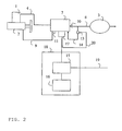
- An electrically controlled air dryer has a so-called in-line regeneration according to fig. 2 for the purpose of drying the air, which means that a by-pass coupling 14 is used instead of the regeneration tank used in a traditional air dryer.
- the by-pass coupling 14 is disposed either in the air dryer 7 or between the pressure tank 3 and the air dryer 7.
- a valve 13 which can be opened and can let back air from the tank to the air dryer.
- the valve 13 is controlled via a wire 20 from an electric control unit 17, which is either an integral part of the air dryer or a separate control unit.
- the air dryer 7 is dried by dry air being taken from the pressure tank 3, after which this dry air is fed back through the air dryer 7 to dry the drying mass in the air dryer 7 until the air dryer has become once again dry.
- the method according to the invention can advantageously be used in an electrically controlled air dryer having a so-called in-line regeneration, since a special evacuation of air from the air tank is made on an already existing system. No extra equipment needs to be fitted on the vehicle in order to perform the capacity check on the compressor.
- the test device 18 in fig. 2 is constituted by a control unit 15 coupled to the ordinary control unit 17 of the air dryer.
- the control unit 15 comprises a processor, memory and suitable input and output circuits which are well known to the person skilled in the art.
- the control unit 15 is also connected to an instrument panel 16 for displaying generated information concerning the compressor capacity.
- the compressor is driven by a motor 2 and the speed of the motor is set to a predefined value prior to the start of the test.
- the compressor pumps air until a predefined pressure P1 is achieved in the pressure tank 3, after which the compressor is relieved of load. When this value of P1 has been found to be stable, i.e. air is not leaking out from the system, a quantity of air is evacuated from the pressure tank 3.
- a valve 13 being held open for a set period, in which the air is allowed to flow out.
- the air flows out through an opening (not shown) of predefined size.
- the pressure in the pressure tank is measured as the air is evacuated and, since the diameter of the opening is known, the discharge flow, and hence the evacuated quantity of air, can be calculated.
- the measurement of the pressure can take place continuously, i.e. analogously throughout the measurement or at regular or irregular intervals.
- an instantaneous pressure P2 is registered by the control unit 15.
- the compressor then refills the pressure tank 3 until the original pressure P1 has been achieved.
- the control unit 15 measures the time t1 consumed when the compressor increases the pressure from the pressure P2 in the pressure tank to the original pressure P1.
- the control unit then checks whether this time t1 lies within a predefined time range tr.
- the predefined time range tr is the time consumed when a compressor with acceptable capacity pumps the corresponding quantity of air. Values of tr for different compressor speeds can be stored in a database in the control unit 15.
- control unit 15 If the time t1 lies outside the predefined time range tr, the control unit 15 generates a error message indicating that the used compressor should be exchanged since its pump capacity is too low. This error message can be shown in an instrument panel 16 forming part of the test device.
- a compressor is fitted on a vehicle. Since the method presupposes that no air consumption occurs during execution of the method, the method is most advantageously carried out after the vehicle has been started and the compressed air system has reached a steady state.
- the compressor is driven by the engine of the vehicle, which has a preset speed of 1000 rpm.
- the pressure P1 is set to a level below the cut-off pressure of the system, for example 11.5 bar.
- a valve is thereafter held open for a certain period, whereupon the air is discharged through a predefined opening of known geometry.
- the air flow through the opening is calculated by continuously measuring the pressure in the pressure tank and the evacuated volume is subsequently calculated. This is done by applying a generally known correlation such as Bernoulli's equation.
- the pressure P1 in the tank is measured prior to the start of the test. Thereafter, the pressure is measured continuously as air is evacuated for a certain period, after which the evacuated quantity of air can be integrated on a forward basis.
- the air flow out in this way a method is obtained which is independent of the volume of the pressure tank and it is thus applicable to different types of vehicle and vehicle variants with variously large compressed air volumes. On certain vehicle variants superstructures can be fitted, which does not affect the measuring method.
- the method can be initiated, for example, when the vehicle is ready for servicing in a workshop and is connected via a connection 19 to a test apparatus in the workshop (not shown).
- the compressor capacity is thereafter reported to a service mechanic via the test apparatus.
- Another way of initiating the method is for the initiation to take place in a menu system present in the vehicle. In this case, the result is shown in the instrument panel 16.
- t1 For a twin-cylinder compressor with 700 cm 3 cubic capacity, a reasonable value of t1 is, for example, 5 seconds, and tr can be 1.7*t1, i.e. a deterioration in pump capacity of around 40% for an approved compressor.
- the compressor is driven by a motor 2 and the speed of the motor is set to a predefined value. The higher the chosen speed, the quicker the test can be performed.
- the compressor pumps air until a predefined pressure P1 is achieved in the pressure tank.
- a quantity of air is evacuated from the pressure tank 3. This is done by evacuating air through a predefined opening until a second pressure P2 in the pressure tank has been achieved and has been registered by the control unit 15.
- the time spent on getting the pressure to drop from the pressure P1 to the pressure P2 is used to calculate, with the aid of Bernoulli's equation, the volume of the evacuated quantity of air.
- the compressor pumps the pressure in the pressure tank 3 back up to the original pressure P1.
- the control unit 15 measures the time t1 consumed when the compressor increases the pressure from the pressure P2 in the pressure tank to the original pressure P1. The control unit then checks whether this time t1 lies within a predefined time range tr. If the time t1 lies outside the predefined time range tr, the control unit generates a error message. This error message can be shown in an instrument panel 16 forming part of the test device.
- Another refinement of the method includes a check that the first pressure (P1) in the pressure tank 3 lies within a predefined pressure range for a certain set period. A leakage of air from the compressed air system or to other reservoirs can thereby be detected. Air leakage from the pressure tank 3 renders the capacity check ineffectual.
- the method can be applied to a compressor forming part of a free-standing air generation unit used, for example, at building sites.
- the monitoring can be remote-controlled via the internet or by telephone. This is particularly advantageous in respect of free-standing air generation units, which are often unmonitored.
- the test can be realized independently by the system.
- the compressor is in this case set to conduct the test at regular intervals, for example each time it is started.
- the system can call a monitoring center and send error messages and/or a report of the compressor capacity.
- Another advantage with the invention is that the capacity check can be realized automatically by an algorithm in the control system ensuring that the test is conducted at programmed regular intervals.
- the method is not only applicable to ground vehicles, but also to, for example, airplanes, boats, etc.
- a flow meter in the predefined hole can be used, instead of calculating the flow from the pressure tank.
Landscapes
- Engineering & Computer Science (AREA)
- Mechanical Engineering (AREA)
- General Engineering & Computer Science (AREA)
- Computer Hardware Design (AREA)
- Control Of Positive-Displacement Pumps (AREA)
- Compressor (AREA)
- Testing Of Devices, Machine Parts, Or Other Structures Thereof (AREA)
- Control Of Positive-Displacement Air Blowers (AREA)
Claims (10)
- Verfahren zur Bewertung der Leistung eines Kompressors (1) mit den folgenden Schritten:- Einstellen der Drehzahl des Kompressors auf einen konstanten und vorher bestimmten Wert,- Füllen eines Drucktanks (3) mit dem Kompressor, so dass ein erster vorher bestimmter Druck, P1, in dem Drucktank (3) erreicht wird, und darauffolgendes Entlasten des Kompressors,- Öffnen eines Ventils (11), so dass eine Luftmenge aus dem Drucktank (3) aus einer Öffnung mit vorher bestimmter Größe ausströmen kann,- Messen des Drucks im Drucktank (3) während des Ablassens der Luft,- Schließen des Ventils (11), sobald die Luftmenge abgelassen wurde,- Erfassen des momentanen Drucks, P2, in dem Drucktank (3), sobald das Ventil (11) geschlossen wurde,- Berechnung der abgelassenen Luftmenge,- Füllen des Drucktanks (3) mit dem Kompressor bis der erste Druck, P1, in dem Drucktank (3) wieder erfasst wird,- Erfassen der Zeit, t1, die für ein Anheben des Drucks in dem Drucktank (3) von dem Druck P2 auf den Druck P1 nötig ist,- Erzeugen einer Fehlermeldung, wenn die Zeit t1 außerhalb eines vorher bestimmten Zeitbereichs, tr, liegt.
- Verfahren nach Anspruch 1, mit dem Schritt des Schließens des Ventils (11) nach einer bestimmten Zeit.
- Verfahren nach Anspruch 1, mit dem Schritt des Schließens des Ventils (11) sobald ein vorher bestimmter Druck P2 in dem Drucktank (3) gemessen wurde.
- Verfahren nach den Ansprüchen 1 bis 3, mit dem Schritt der Überprüfung, ob der Druck, P1, eine vorher bestimmte Zeit, tf, innerhalb eines vorher bestimmten Druckbereichs, Pr, liegt, bevor die Luftmenge aus dem Drucktank (3) abgelassen wird.
- Verfahren nach den Ansprüchen 1 bis 4 mit dem Schritt, dass das Verfahren in vorher bestimmten Zeitintervallen und/oder jedes Mal dann durchgeführt wird, wenn der Kompressor gestartet wird.
- Verfahren nach den Ansprüchen 1 bis 5 mit dem Schritt, dass das Verfahren durch eine Person initiiert wird, die ein in dem Fahrzeug vorhandenes Menüsystem verwendet.
- Verfahren nach den Ansprüchen 1 bis 5, mit dem Schritt, dass das Verfahren durch ein äußeres Signal initiiert wird.
- Vorrichtung zur Bewertung der Leistung eines Luftkompressors (1), mit einem Drucktank (3), der ein Ventil (11) und eine Öffnung bekannter Geometrie aufweist, und einer Steuereinheit (15), wobei die Steuereinheit (15) so ausgelegt ist, dass sie die Drehzahl des Kompressors (1) auf einen vorher bestimmten Wert einstellt und das Ventil (11) öffnet und schließt, um eine bestimmte Luftmenge aus dem Drucktank (3) durch die Öffnung abzulassen, wonach die Steuereinheit (15) über den Kompressor (1) den Drucktank (3) eine gewisse Zeit, t1, lang mit der Luftmenge füllt, und vergleicht, ob die Zeit t1 innerhalb eines vorher bestimmten Zeitbereichs liegt.
- Vorrichtung nach Anspruch 8, dadurch gekennzeichnet, dass die Vorrichtung mit einem Kompressor (1) verbunden ist, der einen Teil einer freistehenden Lufterzeugungseinheit bildet.
- Vorrichtung nach Anspruch 8, dadurch gekennzeichnet, dass die Vorrichtung mit einem an einem Fahrzeug angebrachten Kompressor verbunden ist.
Applications Claiming Priority (3)
| Application Number | Priority Date | Filing Date | Title |
|---|---|---|---|
| SE0300777 | 2003-03-21 | ||
| SE0300777A SE524994C2 (sv) | 2003-03-21 | 2003-03-21 | Metod och anordning för kontroll av en kompressors kapacitet |
| PCT/SE2004/000089 WO2004083801A1 (en) | 2003-03-21 | 2004-01-22 | Method and device for control of the capacity of a compressor |
Publications (2)
| Publication Number | Publication Date |
|---|---|
| EP1608946A1 EP1608946A1 (de) | 2005-12-28 |
| EP1608946B1 true EP1608946B1 (de) | 2007-03-28 |
Family
ID=20290738
Family Applications (1)
| Application Number | Title | Priority Date | Filing Date |
|---|---|---|---|
| EP04704376A Expired - Lifetime EP1608946B1 (de) | 2003-03-21 | 2004-01-22 | Verfahren und vorrichtung zur leistungsmessung eines kompressors |
Country Status (7)
| Country | Link |
|---|---|
| US (1) | US7287423B2 (de) |
| EP (1) | EP1608946B1 (de) |
| AT (1) | ATE358272T1 (de) |
| BR (1) | BRPI0408596A (de) |
| DE (1) | DE602004005579T2 (de) |
| SE (1) | SE524994C2 (de) |
| WO (1) | WO2004083801A1 (de) |
Cited By (1)
| Publication number | Priority date | Publication date | Assignee | Title |
|---|---|---|---|---|
| CN102645373A (zh) * | 2011-02-22 | 2012-08-22 | 上海德朗汽车零部件制造有限公司 | 一种用于气气中冷器压力交变试验的计算机测控系统 |
Families Citing this family (18)
| Publication number | Priority date | Publication date | Assignee | Title |
|---|---|---|---|---|
| CN1332133C (zh) * | 2005-03-13 | 2007-08-15 | 周巽 | 通过限时排气体积判定压缩机关键特性合格与否的方法 |
| CN100419264C (zh) * | 2005-03-13 | 2008-09-17 | 葛焕森 | 通过限定排气体积的耗用时间判定压缩机关键特性的方法 |
| DE102005019783A1 (de) | 2005-04-28 | 2006-11-09 | Continental Aktiengesellschaft | Niveauregelanlage für ein Kraftfahrzeug |
| CN101672729B (zh) * | 2009-10-14 | 2011-02-16 | 清华大学 | 高空低气压内燃机压气机特性模拟试验台 |
| DE102010024059A1 (de) * | 2010-06-17 | 2011-12-22 | Knorr-Bremse Systeme für Nutzfahrzeuge GmbH | Druckluftanlage für Nutzfahrzeuge und Verfahren zum Bereitstellen und Verwalten von Druckluft mittels einer Druckluftanlage |
| CN101984256B (zh) * | 2010-11-16 | 2012-10-03 | 潍柴动力股份有限公司 | 空气压缩机加减负荷装置 |
| CN102645374B (zh) * | 2011-02-22 | 2013-12-25 | 上海德朗汽车零部件制造有限公司 | 一种气气中冷器压力交变试验系统 |
| CN102645337B (zh) * | 2011-02-22 | 2014-10-15 | 上海理工技术转移有限公司 | 用于气气中冷器压力交变试验的气循环系统 |
| CN102654469A (zh) * | 2012-05-10 | 2012-09-05 | 沈阳仪表科学研究院 | 压力元件耐火试验装置 |
| CN102749207B (zh) * | 2012-07-11 | 2014-11-05 | 杭州沃镭科技有限公司 | 一种汽车用空气干燥器安全压力测试装置 |
| KR101532485B1 (ko) * | 2013-09-17 | 2015-06-30 | 코리아에프티 주식회사 | 차량용 캐니스터 검사장치 |
| CN106194698B (zh) * | 2016-06-28 | 2018-09-14 | 上海高桥捷派克石化工程建设有限公司 | 压缩机试车台控制系统和控制方法 |
| CN106197977B (zh) * | 2016-07-06 | 2018-07-13 | 公安部天津消防研究所 | 气体灭火系统用高压、大流量单向阀动作试验装置及方法 |
| CN106499651B (zh) * | 2016-10-20 | 2017-11-28 | 北京理工大学 | 一种离心压气机非稳态特性试验台及试验方法 |
| JP6851953B2 (ja) * | 2017-10-30 | 2021-03-31 | アークレイ株式会社 | ポンプ駆動方法 |
| CN108931277B (zh) * | 2018-07-06 | 2020-06-19 | 西安工程大学 | 一种纺织厂压缩空气系统总泄漏量的检测方法 |
| CN113309692B (zh) * | 2021-05-27 | 2023-02-03 | 广东电网有限责任公司 | 一种gis设备空气压力补给方法、装置、介质及电子设备 |
| CN115683484A (zh) * | 2022-10-10 | 2023-02-03 | 浙江氢途科技有限公司 | 一种新型燃料电池气密性检测设备及方法 |
Family Cites Families (7)
| Publication number | Priority date | Publication date | Assignee | Title |
|---|---|---|---|---|
| US2782637A (en) * | 1955-07-13 | 1957-02-26 | Gen Electric | Apparatus for testing compressors |
| US4052135A (en) * | 1976-05-11 | 1977-10-04 | Gardner-Denver Company | Control system for helical screw compressor |
| SE432465B (sv) * | 1980-06-02 | 1984-04-02 | Sullair Tech Ab | Ventilarrangemang for kapacitetsreglering av skruvkompressorer |
| US4676095A (en) * | 1985-11-22 | 1987-06-30 | Columbia Gas System Service Corp. | Apparatus for measuring the work performed by a gas compressor |
| US5811669A (en) * | 1997-02-20 | 1998-09-22 | Rodolfo Esteban Polonyi | Cycling compressor performance metering |
| US6227815B1 (en) * | 1999-06-30 | 2001-05-08 | Campbell Hausfeld/Scott Fetzer Company | Pressure control for a reciprocating compressor |
| US7328587B2 (en) * | 2004-01-23 | 2008-02-12 | York International Corporation | Integrated adaptive capacity control for a steam turbine powered chiller unit |
-
2003
- 2003-03-21 SE SE0300777A patent/SE524994C2/sv not_active IP Right Cessation
-
2004
- 2004-01-22 AT AT04704376T patent/ATE358272T1/de not_active IP Right Cessation
- 2004-01-22 DE DE602004005579T patent/DE602004005579T2/de not_active Expired - Lifetime
- 2004-01-22 WO PCT/SE2004/000089 patent/WO2004083801A1/en not_active Ceased
- 2004-01-22 EP EP04704376A patent/EP1608946B1/de not_active Expired - Lifetime
- 2004-01-22 BR BRPI0408596-5A patent/BRPI0408596A/pt not_active IP Right Cessation
-
2006
- 2006-09-21 US US11/162,755 patent/US7287423B2/en not_active Expired - Fee Related
Cited By (1)
| Publication number | Priority date | Publication date | Assignee | Title |
|---|---|---|---|---|
| CN102645373A (zh) * | 2011-02-22 | 2012-08-22 | 上海德朗汽车零部件制造有限公司 | 一种用于气气中冷器压力交变试验的计算机测控系统 |
Also Published As
| Publication number | Publication date |
|---|---|
| SE0300777D0 (sv) | 2003-03-21 |
| US7287423B2 (en) | 2007-10-30 |
| EP1608946A1 (de) | 2005-12-28 |
| DE602004005579T2 (de) | 2007-12-06 |
| ATE358272T1 (de) | 2007-04-15 |
| BRPI0408596A (pt) | 2006-03-21 |
| US20070012098A1 (en) | 2007-01-18 |
| SE0300777L (sv) | 2004-09-22 |
| DE602004005579D1 (de) | 2007-05-10 |
| SE524994C2 (sv) | 2004-11-09 |
| WO2004083801A1 (en) | 2004-09-30 |
Similar Documents
| Publication | Publication Date | Title |
|---|---|---|
| EP1608946B1 (de) | Verfahren und vorrichtung zur leistungsmessung eines kompressors | |
| US7353692B2 (en) | Leakage tester | |
| CN110284953B (zh) | 尿素泵老化程度评估方法和装置 | |
| CN110678643B (zh) | 维护系统 | |
| CN101253086A (zh) | 用于确定机动车制动系统中的初始压力的方法 | |
| JP2019167836A (ja) | 異常診断装置および異常診断方法 | |
| EP2999878A1 (de) | Verfahren und vorrichtung zur funktionskontrolle einer hochdruckkraftstoffpumpe | |
| WO2019181996A1 (ja) | 異常診断装置および異常診断方法 | |
| CN213022137U (zh) | 一种用于氢能源汽车的气密检测系统 | |
| CN100354167C (zh) | 制动控制装置及其故障诊断方法 | |
| JP2002364396A (ja) | 燃料混合充填システム | |
| CN116929639B (zh) | 一种提升发动机壳体气密性检测设备效率的方法 | |
| JPH0743280A (ja) | 高圧ガス容器の非水槽式耐圧膨張試験方法及び装置 | |
| CN214408457U (zh) | 一种管道破裂阀高压试验装置 | |
| JP3542086B2 (ja) | 天然ガスの充填方法 | |
| CN115503673A (zh) | 一种车辆制动偏软的处理方法、装置、设备及存储介质 | |
| CN104180877B (zh) | 一种燃油传感器与组合仪表匹配试验台 | |
| CN113795663A (zh) | 用于确定空气质量的方法和水直接喷射系统 | |
| CN114062145B (zh) | 一种模具内水管测试设备及水管检测系统 | |
| CN221664863U (zh) | 具有双电机式高低压充气组件的多功能车载充气泵 | |
| CN119825844A (zh) | 排气控制方法、装置、车辆和存储介质 | |
| EP3697506B1 (de) | Verfahren zum betrieb eines feuerschutzwasserverteilungssystems | |
| CN211013841U (zh) | 容器耐压测试油液回收系统 | |
| CN114961991A (zh) | 泄漏诊断方法及泄漏诊断系统 | |
| CN119536387A (zh) | 气压控制方法、装置、水路控制系统及清洗车 |
Legal Events
| Date | Code | Title | Description |
|---|---|---|---|
| PUAI | Public reference made under article 153(3) epc to a published international application that has entered the european phase |
Free format text: ORIGINAL CODE: 0009012 |
|
| 17P | Request for examination filed |
Effective date: 20051021 |
|
| AK | Designated contracting states |
Kind code of ref document: A1 Designated state(s): AT BE BG CH CY CZ DE DK EE ES FI FR GB GR HU IE IT LI LU MC NL PT RO SE SI SK TR |
|
| AX | Request for extension of the european patent |
Extension state: AL LT LV MK |
|
| DAX | Request for extension of the european patent (deleted) | ||
| GRAP | Despatch of communication of intention to grant a patent |
Free format text: ORIGINAL CODE: EPIDOSNIGR1 |
|
| GRAS | Grant fee paid |
Free format text: ORIGINAL CODE: EPIDOSNIGR3 |
|
| GRAA | (expected) grant |
Free format text: ORIGINAL CODE: 0009210 |
|
| AK | Designated contracting states |
Kind code of ref document: B1 Designated state(s): AT BE BG CH CY CZ DE DK EE ES FI FR GB GR HU IE IT LI LU MC NL PT RO SE SI SK TR |
|
| PG25 | Lapsed in a contracting state [announced via postgrant information from national office to epo] |
Ref country code: FI Free format text: LAPSE BECAUSE OF FAILURE TO SUBMIT A TRANSLATION OF THE DESCRIPTION OR TO PAY THE FEE WITHIN THE PRESCRIBED TIME-LIMIT Effective date: 20070328 Ref country code: CH Free format text: LAPSE BECAUSE OF FAILURE TO SUBMIT A TRANSLATION OF THE DESCRIPTION OR TO PAY THE FEE WITHIN THE PRESCRIBED TIME-LIMIT Effective date: 20070328 Ref country code: LI Free format text: LAPSE BECAUSE OF FAILURE TO SUBMIT A TRANSLATION OF THE DESCRIPTION OR TO PAY THE FEE WITHIN THE PRESCRIBED TIME-LIMIT Effective date: 20070328 Ref country code: SI Free format text: LAPSE BECAUSE OF FAILURE TO SUBMIT A TRANSLATION OF THE DESCRIPTION OR TO PAY THE FEE WITHIN THE PRESCRIBED TIME-LIMIT Effective date: 20070328 Ref country code: BE Free format text: LAPSE BECAUSE OF FAILURE TO SUBMIT A TRANSLATION OF THE DESCRIPTION OR TO PAY THE FEE WITHIN THE PRESCRIBED TIME-LIMIT Effective date: 20070328 Ref country code: AT Free format text: LAPSE BECAUSE OF FAILURE TO SUBMIT A TRANSLATION OF THE DESCRIPTION OR TO PAY THE FEE WITHIN THE PRESCRIBED TIME-LIMIT Effective date: 20070328 |
|
| REG | Reference to a national code |
Ref country code: GB Ref legal event code: FG4D |
|
| REG | Reference to a national code |
Ref country code: CH Ref legal event code: EP |
|
| REF | Corresponds to: |
Ref document number: 602004005579 Country of ref document: DE Date of ref document: 20070510 Kind code of ref document: P |
|
| REG | Reference to a national code |
Ref country code: IE Ref legal event code: FG4D |
|
| PG25 | Lapsed in a contracting state [announced via postgrant information from national office to epo] |
Ref country code: ES Free format text: LAPSE BECAUSE OF FAILURE TO SUBMIT A TRANSLATION OF THE DESCRIPTION OR TO PAY THE FEE WITHIN THE PRESCRIBED TIME-LIMIT Effective date: 20070709 |
|
| REG | Reference to a national code |
Ref country code: SE Ref legal event code: TRGR |
|
| PG25 | Lapsed in a contracting state [announced via postgrant information from national office to epo] |
Ref country code: PT Free format text: LAPSE BECAUSE OF FAILURE TO SUBMIT A TRANSLATION OF THE DESCRIPTION OR TO PAY THE FEE WITHIN THE PRESCRIBED TIME-LIMIT Effective date: 20070828 |
|
| ET | Fr: translation filed | ||
| REG | Reference to a national code |
Ref country code: CH Ref legal event code: PL |
|
| PG25 | Lapsed in a contracting state [announced via postgrant information from national office to epo] |
Ref country code: SK Free format text: LAPSE BECAUSE OF FAILURE TO SUBMIT A TRANSLATION OF THE DESCRIPTION OR TO PAY THE FEE WITHIN THE PRESCRIBED TIME-LIMIT Effective date: 20070328 |
|
| PG25 | Lapsed in a contracting state [announced via postgrant information from national office to epo] |
Ref country code: RO Free format text: LAPSE BECAUSE OF FAILURE TO SUBMIT A TRANSLATION OF THE DESCRIPTION OR TO PAY THE FEE WITHIN THE PRESCRIBED TIME-LIMIT Effective date: 20070328 Ref country code: CZ Free format text: LAPSE BECAUSE OF FAILURE TO SUBMIT A TRANSLATION OF THE DESCRIPTION OR TO PAY THE FEE WITHIN THE PRESCRIBED TIME-LIMIT Effective date: 20070328 |
|
| PG25 | Lapsed in a contracting state [announced via postgrant information from national office to epo] |
Ref country code: DK Free format text: LAPSE BECAUSE OF FAILURE TO SUBMIT A TRANSLATION OF THE DESCRIPTION OR TO PAY THE FEE WITHIN THE PRESCRIBED TIME-LIMIT Effective date: 20070328 |
|
| PLBE | No opposition filed within time limit |
Free format text: ORIGINAL CODE: 0009261 |
|
| STAA | Information on the status of an ep patent application or granted ep patent |
Free format text: STATUS: NO OPPOSITION FILED WITHIN TIME LIMIT |
|
| 26N | No opposition filed |
Effective date: 20080102 |
|
| PG25 | Lapsed in a contracting state [announced via postgrant information from national office to epo] |
Ref country code: GR Free format text: LAPSE BECAUSE OF FAILURE TO SUBMIT A TRANSLATION OF THE DESCRIPTION OR TO PAY THE FEE WITHIN THE PRESCRIBED TIME-LIMIT Effective date: 20070629 |
|
| PG25 | Lapsed in a contracting state [announced via postgrant information from national office to epo] |
Ref country code: MC Free format text: LAPSE BECAUSE OF NON-PAYMENT OF DUE FEES Effective date: 20080131 |
|
| PG25 | Lapsed in a contracting state [announced via postgrant information from national office to epo] |
Ref country code: IE Free format text: LAPSE BECAUSE OF NON-PAYMENT OF DUE FEES Effective date: 20080122 Ref country code: EE Free format text: LAPSE BECAUSE OF FAILURE TO SUBMIT A TRANSLATION OF THE DESCRIPTION OR TO PAY THE FEE WITHIN THE PRESCRIBED TIME-LIMIT Effective date: 20070328 |
|
| PG25 | Lapsed in a contracting state [announced via postgrant information from national office to epo] |
Ref country code: CY Free format text: LAPSE BECAUSE OF FAILURE TO SUBMIT A TRANSLATION OF THE DESCRIPTION OR TO PAY THE FEE WITHIN THE PRESCRIBED TIME-LIMIT Effective date: 20070328 |
|
| PG25 | Lapsed in a contracting state [announced via postgrant information from national office to epo] |
Ref country code: BG Free format text: LAPSE BECAUSE OF FAILURE TO SUBMIT A TRANSLATION OF THE DESCRIPTION OR TO PAY THE FEE WITHIN THE PRESCRIBED TIME-LIMIT Effective date: 20070628 |
|
| PG25 | Lapsed in a contracting state [announced via postgrant information from national office to epo] |
Ref country code: HU Free format text: LAPSE BECAUSE OF FAILURE TO SUBMIT A TRANSLATION OF THE DESCRIPTION OR TO PAY THE FEE WITHIN THE PRESCRIBED TIME-LIMIT Effective date: 20070929 Ref country code: LU Free format text: LAPSE BECAUSE OF NON-PAYMENT OF DUE FEES Effective date: 20080122 |
|
| PG25 | Lapsed in a contracting state [announced via postgrant information from national office to epo] |
Ref country code: TR Free format text: LAPSE BECAUSE OF FAILURE TO SUBMIT A TRANSLATION OF THE DESCRIPTION OR TO PAY THE FEE WITHIN THE PRESCRIBED TIME-LIMIT Effective date: 20070328 |
|
| PGFP | Annual fee paid to national office [announced via postgrant information from national office to epo] |
Ref country code: DE Payment date: 20120118 Year of fee payment: 9 |
|
| PGFP | Annual fee paid to national office [announced via postgrant information from national office to epo] |
Ref country code: GB Payment date: 20120118 Year of fee payment: 9 Ref country code: SE Payment date: 20120112 Year of fee payment: 9 Ref country code: IT Payment date: 20120114 Year of fee payment: 9 |
|
| PGFP | Annual fee paid to national office [announced via postgrant information from national office to epo] |
Ref country code: NL Payment date: 20120117 Year of fee payment: 9 |
|
| PGFP | Annual fee paid to national office [announced via postgrant information from national office to epo] |
Ref country code: FR Payment date: 20130204 Year of fee payment: 10 |
|
| REG | Reference to a national code |
Ref country code: NL Ref legal event code: V1 Effective date: 20130801 |
|
| REG | Reference to a national code |
Ref country code: SE Ref legal event code: EUG |
|
| GBPC | Gb: european patent ceased through non-payment of renewal fee |
Effective date: 20130122 |
|
| PG25 | Lapsed in a contracting state [announced via postgrant information from national office to epo] |
Ref country code: NL Free format text: LAPSE BECAUSE OF NON-PAYMENT OF DUE FEES Effective date: 20130801 Ref country code: SE Free format text: LAPSE BECAUSE OF NON-PAYMENT OF DUE FEES Effective date: 20130123 Ref country code: DE Free format text: LAPSE BECAUSE OF NON-PAYMENT OF DUE FEES Effective date: 20130801 |
|
| REG | Reference to a national code |
Ref country code: DE Ref legal event code: R119 Ref document number: 602004005579 Country of ref document: DE Effective date: 20130801 |
|
| PG25 | Lapsed in a contracting state [announced via postgrant information from national office to epo] |
Ref country code: GB Free format text: LAPSE BECAUSE OF NON-PAYMENT OF DUE FEES Effective date: 20130122 |
|
| REG | Reference to a national code |
Ref country code: FR Ref legal event code: ST Effective date: 20140930 |
|
| PG25 | Lapsed in a contracting state [announced via postgrant information from national office to epo] |
Ref country code: FR Free format text: LAPSE BECAUSE OF NON-PAYMENT OF DUE FEES Effective date: 20140131 |
|
| PG25 | Lapsed in a contracting state [announced via postgrant information from national office to epo] |
Ref country code: IT Free format text: LAPSE BECAUSE OF NON-PAYMENT OF DUE FEES Effective date: 20140122 |