EP1607289A1 - Zündschloss für ein Kraftfahrzeug - Google Patents
Zündschloss für ein Kraftfahrzeug Download PDFInfo
- Publication number
- EP1607289A1 EP1607289A1 EP05013106A EP05013106A EP1607289A1 EP 1607289 A1 EP1607289 A1 EP 1607289A1 EP 05013106 A EP05013106 A EP 05013106A EP 05013106 A EP05013106 A EP 05013106A EP 1607289 A1 EP1607289 A1 EP 1607289A1
- Authority
- EP
- European Patent Office
- Prior art keywords
- rotor
- lever
- key
- ignition lock
- receptacle
- Prior art date
- Legal status (The legal status is an assumption and is not a legal conclusion. Google has not performed a legal analysis and makes no representation as to the accuracy of the status listed.)
- Granted
Links
Images


Classifications
-
- B—PERFORMING OPERATIONS; TRANSPORTING
- B60—VEHICLES IN GENERAL
- B60R—VEHICLES, VEHICLE FITTINGS, OR VEHICLE PARTS, NOT OTHERWISE PROVIDED FOR
- B60R25/00—Fittings or systems for preventing or indicating unauthorised use or theft of vehicles
- B60R25/20—Means to switch the anti-theft system on or off
- B60R25/24—Means to switch the anti-theft system on or off using electronic identifiers containing a code not memorised by the user
- B60R25/248—Electronic key extraction prevention
-
- B—PERFORMING OPERATIONS; TRANSPORTING
- B60—VEHICLES IN GENERAL
- B60R—VEHICLES, VEHICLE FITTINGS, OR VEHICLE PARTS, NOT OTHERWISE PROVIDED FOR
- B60R25/00—Fittings or systems for preventing or indicating unauthorised use or theft of vehicles
- B60R25/01—Fittings or systems for preventing or indicating unauthorised use or theft of vehicles operating on vehicle systems or fittings, e.g. on doors, seats or windscreens
- B60R25/04—Fittings or systems for preventing or indicating unauthorised use or theft of vehicles operating on vehicle systems or fittings, e.g. on doors, seats or windscreens operating on the propulsion system, e.g. engine or drive motor
-
- B—PERFORMING OPERATIONS; TRANSPORTING
- B60—VEHICLES IN GENERAL
- B60R—VEHICLES, VEHICLE FITTINGS, OR VEHICLE PARTS, NOT OTHERWISE PROVIDED FOR
- B60R25/00—Fittings or systems for preventing or indicating unauthorised use or theft of vehicles
- B60R25/20—Means to switch the anti-theft system on or off
- B60R25/2063—Ignition switch geometry
Definitions
- the invention relates to an ignition lock according to the preamble of patent claim 1.
- the ignition and related controls are components of the ignition system in Motor vehicle.
- the ignition lock has a rotor with a receptacle into which the electronic key is insertable.
- the rotor is by means of the key between one initial position and several positions of movement manually movable by rotation.
- After positive evaluation of one between the Key and the ignition switch exchanged electronic codes is at least one function that can be effected by the ignition, such as the switching on of consumers in the Motor vehicle, such as radio, lighting, etc., such as starting the Motor vehicle o. The like., Released.
- To trigger the function of the rotor acts in the respective movement position accordingly to a switching element.
- Such ignition lock systems are also with a so-called "KeylessGo" functionality developed in which it is sufficient that the user the electronic key, a Identification (ID) geber, a smartcard o. The like. With you leads. An authentication of the Key o. The like. Is then carried out automatically when the user in the Motor vehicle is located. For the actual boot process, the user moves for example, a mounted on the ignition actuator.
- ID Identification
- smartcard o. The like.
- the invention has for its object to further develop the ignition.
- the ignition lock according to the invention is on the rotor and / or in the rotor and / or by the Rotor at least one ignition lock function, such as the blocking and / or release of the Key in the ignition, the operation of a switch by means of the key in Ignition lock, the blocking and / or release of the movement of the rotor o.
- the ignition lock function such as the blocking and / or release of the Key in the ignition, the operation of a switch by means of the key in Ignition lock, the blocking and / or release of the movement of the rotor o.
- This is in a simple way the reliability of the ignition further increased.
- Further embodiments of the invention are the subject of Dependent claims.
- the selector lever of Geretes connected to one side of a Bowden cable.
- the other side of the Bowden cable has a free-standing finger, which protrudes into the ignition lock such that over the Position of the selector lever the release of the key for removal from the receptacle is controlled.
- a lever interacting with the finger is used to control the Release of the key and / or the selector lever from a contour located on the rotor emotional.
- a compression spring acts on the lever such that the lever on a contour is applied to the rotor.
- the lever By rotation of the rotor, the lever is pivotable. Of the Finger is supported on the lever and / or the lever is blocked by the finger.
- the rotary bearing for the movable rotor in the manner of a cylinder be formed, for example, consisting of a cylinder front part and a Cylinder rump.
- the recognition of the key can be further designed by that the lever is loaded by a compression spring such that the lever in the plug of the Key in.
- the key-plug switch can be placed on a printed circuit board Housing the ignition lock be located.
- the other side of the lever pivots when Reaching the end position of the key in the inclusion in a tube-like cylinder on the rotor, so that the key-inserted switch by means of the tube-like cylinder is actuated upon movement of the rotor.
- the lever protrudes into a pivoted position in one Recess in the cylinder rear part, in order not to insert a key rotation of the To prevent rotor with safety.
- the tube-like cylinder may have additional switches, such as a wake-up switch or an ELV (electric steering lock) switch, actuate.
- additional switches such as a wake-up switch or an ELV (electric steering lock) switch, actuate.
- the actuator for the KeylessGo functionality may also be a Handle acting alternatively to the action of the electronic key the switching element is insertable into the receptacle. This can be done by pressing the Handle in the initial position of the rotor switching to one in the ignition located switch in the manner of a key-trigger switch are acted.
- This additional key-trigger switch is located in the receptacle Key permanently and in the recording befindaji handle only in their Switched operation, which in a simple way between KeylessGo- as well NonKeylessGo operation can be distinguished.
- the handle has an actuator with a Tappet on, wherein the handle by means of the plunger moving on a sleeve in the rotor acts.
- the key moves when inserted into the receptacle, the sleeve directly.
- the sleeve finally actuates via an actuator part, which is provided with a spring, the key-trigger switch.
- a mechanical lock gives the rotation of the rotor only to positive Evaluation of the code free.
- the mechanical Lock out of a lever turnstile.
- a lever of the lever turnstile is applied to the rotor, wherein the rotor has a contour for deflecting the lever.
- the Lever acts like an electromagnetically actuated pawl of the lever turnstile in such a way together that the lever for deflecting is releasable and / or the deflection of the lever Is blocked.
- a simple structure of such a lever-turnstile is given by the fact that the lever is applied by means of a compression spring on the rotor.
- the contour of the rotor has a blocking edge on. This locking edge acts with a corresponding locking edge on the lever so together that the movement of the rotor is lockable.
- either the key or a handle for operating the ignition lock insertable may be arranged in the rotor, a movable gate valve. If neither the Key still the handle is inserted into the receptacle, is the locking slide with Recesses on the pivot bearing in engagement so that rotation of the rotor is locked. When the key is inserted into the receptacle, the gate valve is disengaged with the recesses on the pivot bearing, so that a rotation of the rotor is released. When the handle is inserted into the receptacle, the gate valve also comes in Engagement with the recesses on the pivot bearing, so that a rotation of the rotor locked is.
- the gate valve has two preassembled Compression springs, so that the locking slide during its installation in the recess on Swivel engages. Furthermore, the gate valve on a web, when plugging the key in the receptacle is supported on the front part of the key such that the Locking slide is deflected to solve the blocking function.
- the handle has a groove on, in which the web engages when inserting the handle into the receptacle, such that the Lock slide remains in its blocking function performing position.
- Pivot bearings for the rotor may be formed in the manner of a cylinder.
- Fig. 1 is an ignition lock 1 as an electrical component for a motor vehicle of the Front and to see in Fig. 2 from the back.
- the ignition lock 1 has a housing 2.
- the ignition lock 1 is part of an electronic shown in Fig. 4 Key 3, an identification (ID) provider, a smart card or the like - hereinafter only still with key 3 designates - cooperating ignition lock system for Operator-independent driving authorization in the manner of KeylessGo functionality and / or for the operator-dependent driving authorization in the form of a NonKeylessGo functionality in the motor vehicle.
- the key 3 is in the possession of the authorized User, whereby he has the driving authorization for the motor vehicle.
- the so-called KeylessGo functionality will be an authentication between the Key 3, the user, for example, in a trouser pocket o. The like. With him leads, and the ignition lock system performed after the successful completion of the user Motor vehicle in operation.
- the ignition lock 1 contains at least one switching element 7, the is shown schematically in Fig. 18, can be acted upon by means of a handle 4.
- Fig. 3 is visible in a more detailed embodiment, this is the handle 4 in a receptacle. 5 can be inserted in the ignition lock 1 and remains there, if not the one described below Emergency operation should take place.
- a manual operation of the located in the receptacle 5, in the type of a push button designed handle 4 by the user by the Handle 4 from a zero position in at least one operating position by pressing is moved manually, then leads to the switching action of the handle 4 by means of a Actuator 6 in the operating position on the switching element 7.
- the authentication is triggered, wherein between the Key 3 and the ignition 1 or a control unit in the ignition lock system electronic code is exchanged. After positive evaluation of the code and thus after successful authentication then the starting of the motor vehicle in the KeylessGo functionality is triggered so that starting is a function of the Handle 4 is exercisable.
- the starting of the motor vehicle in the KeylessGo functionality is triggered so that starting is a function of the Handle 4 is exercisable.
- the Motor vehicles can from the ignition 1 more features, such as switching of consumers in the motor vehicle o. The like., Released and / or effected.
- the ignition 1 also allows emergency operation without KeylessGo functionality, ie in the nature of a NonKeylessGo functionality, for example, with empty energy storage of the Key 3 o.
- the handle 4 optionally the electronic key. 3 itself in the receptacle 5 can be inserted, which is shown in more detail in Fig. 4.
- the Handle 4 are removed from the receptacle 5. Is the electronic key 3 in the Recording 5 introduced, it is in a known manner, energy from the ignition 1 on the Key 3 transferred to its operation. Then, between the key 3 and the Ignition 1 again a code to be exchanged for authentication.
- the code lets For example, in the form of infrared signals arranged in the ignition 1 Transmit light guide 8, as shown in Fig. 4 can be seen.
- the recording 5 is within one movable rotor 9 is arranged, which upon rotation by means of the key 3 from a Starting position in at least one rotational position on not shown switching elements switching acts, so that after successful authentication turn a Commissioning of the motor vehicle o. The like. Is feasible.
- the pivot bearing 45 for the movable rotor 9 is in the manner of a cylinder consisting of a cylinder front part 25 'and a cylinder rear part 25, as shown in Fig. 12 can be seen formed.
- the ignition 1 is supplied with electrical energy and exchanges data with others Control devices in the motor vehicle off.
- the housing 2 with an electric Plug connection 10 is provided, to which an associated electrical connector 11 is plugged.
- the plug connection 10 can be seen in FIG. 2 and the plug 11 in FIG.
- the plug 11 is secured in the housing 2 by means of a catch to the effect that this is difficult and can be solved under great time to remove the plug 11.
- a Abziehschutz 12 for the electrical connector 11 at the plug connection 10 arranged.
- the peel-off protection 12 is between a pre-fixed position, the in Fig. 5 to see, as well as a latched end position, which is shown in Fig. 6, movable. It is the Abziehtik 12 with little force locked in the end position and only with large force unlocked from the end position.
- the additional Abziehschutz 12 is laterally on the housing 2 in the region of the connector collar 54 prefixed by means of a pre-locking.
- This prefixing is designed so that the entire Ignition 1 can be moved to the additional pull-12 and while the Pre-fixing is not solved.
- the Abziehtik 12 After the plug 11 is inserted into the plug collar 54 and is latched, the Abziehtik 12 from the pre-fixed position in the end position pushed.
- the transition from the Vorrastung in the Endrastung is designed so that the For this required force is low, but vice versa when pushing back or loosening the Final locking in the Vorrastung turn larger.
- the peel-off protection 12 provides additional theft protection, since the Removing the plug 11 is no longer possible without much time.
- the motor vehicle may be used in accordance with the so-called "shift lock" only in position 'P' of the selector lever for the transmission possible be to turn back the key 3 in the starting position '0' of the ignition 1 and then remove the key 3 from the receptacle 5. Furthermore, it may only be be possible with turned key 3 from the position 'P' in another position switch.
- the not shown selector lever of the transmission with one side of a in Fig. 2 visible Bowden cable 13 connected. The other side of the Bowden cable 13, the 2 is attached to the housing 2, has one shown in Fig. 7 and Fig.
- a compression spring 17 acts, which causes the lever 15 always rests on the rotor 9.
- the co-rotating contour 16 attached. This contour 16 is formed so that the spring-loaded lever 15 when turning the rotor 9 make a pivoting movement can, as can be seen by comparing FIGS. 9 and 10.
- the starting position '0' of the Ignition 1 now protrudes as shown in FIG. 9 of the fingers 14 of the Bowden cable 13 via the lever 15. If one then tries to move the selector lever for the transmission out of the position 'P', then the finger 14 is supported on the lever 15.
- the deduction of the key 3 and the deliberate movement of the selector lever from the position 'P' are affected.
- the operator must therefore consciously the removal of the key 3 and / or moving the selector lever take place. It is not possible to remove the key 3 when the selector lever is not in Position 'P' is. Furthermore, no movement of the selector lever is possible if the key 3 is not turned.
- the electrical switch 18 is the so-called "key-inserted switch” (SSS), which is located on a housing 2, in Fig. 11 shown printed circuit board 19 is arranged.
- the circuit board 19 also takes the electrical and / or electronic components 30 of the electronic module 49 for the Control of the ignition lock 1 on.
- This SSS switch 18 is inserted upon insertion of the Key 3 in the receptacle 5 and / or is located in the receptacle 5 key 3 actuated.
- the actuation path of the SSS switch 18 is about 2 mm, while the path of the Key 3, however, is about 4 + 2mm.
- a further lever 20 how to recognizes with reference to FIG. 12.
- the lever 20 rotates with the rotor 9.
- One side of the Levers 20 extends into the path of the key 3 in the receptacle 5 into it.
- the lever 20 is deflected such that the other side of the lever 20th the SSS switch 18 is actuated.
- the insertion of the key 3 is from the bottom of the rotor 9 in Fig. 14 to 17th to see.
- Fig. 14 the position of the lever 20 is shown when no key 3 in the Recording 5 is located. If the key 3 is inserted into the receptacle 5, wherein the Key 3 which moves one side of the lever 20 so pivots upon reaching the End ein the other side of the lever 20 in a tube-like cylinder 22, as shown in FIG. 15 can be seen. The inside of the lever 20 is then in the same position as the Inside the tube-like cylinder 22.
- lever 20 Another function of the lever 20 is in non-inserted key 3 and even with missing handle 4, which is the so-called "button start-stop" TSS is to prevent rotatability of the rotor 9, to manipulation of the Ignition lock 1 excluded. This is achieved in that the lever 20 in swung-out position in a recess 24 in the cylinder rear part 25 protrudes, how to with reference to FIG. 16.
- the tube-like cylinder 22 is also still for articulation of the Wake-up switch 26 (so-called "H0 switch”) and for operating an ELV switch 27th used, which can be seen in Fig. 11.
- the wake-up switch 26 is used to switch the Electronics in the ignition 1 of an energy-saving sleep state in the Operating state due to the start of the rotary motion of the rotor 9.
- the ELV switch 27 controls the electric steering lock in the motor vehicle.
- lever 20 is advantageously the possibility of an inserted key. 3 to recognize electronically on the circuit board 19. Also over the entire plug way of the Key 3, the SSS switch 18 remains actuated. Furthermore, the rotor 9 with the aid of Key 3 are rotated while the SSS switch 18 remains actuated.
- the motor vehicle should be operated by means of Handle 4, so the button-start-stop TSS, which is in the electronic ignition 1 is located, started and stopped.
- the button-start-stop TSS which is in the electronic ignition 1 is located, started and stopped.
- additional switches 7, the so-called “key-trigger switch” SAS there is a distinction of operation by means of a key 3 or handle 4 serves.
- the SAS switch 7 is permanently in befindlichem in the recording 5 key 3 connected. When located in the receptacle 5 handle 4 of the SAS switch 7 is, however switched only in their actuation by the user in the operating position.
- the SAS switch 7 is also positioned on the circuit board 19.
- the handle 4 is, based on the retaining collar 52 of the handle 4 and the collar 51 of the Key 3, about 2.25 mm shorter than the key 3.
- By pressure on the handle 4 the two plungers 32 are pressed out of the handle 4 and so are the same Length difference to the sleeve 33 from. This ensures that the sleeve 33 in the rotor. 9 both in NonKeylessGo mode by means of the key 3 of FIG. 20 as well as after completed stroke of the handle 4 in Keyless Go operation according to FIG.
- NonKeylessGo operation the sleeve 33 and the spring-loaded actuator part 35 rotate With. So that the SAS switch 7 remains actuated, 9 is in the direction of rotation of the rotor Height of the end position of the actuator 35 a not further shown cylinder tube, the is configured comparable to the tube-like cylinder 22 of FIG. 14, attached. If the rotor 9 now rotates, the actuation of the SAS switch 7 is triggered by the actuator part 35 transferred to this cylinder tube. This ensures that the SAS switch 7 in NonKeylessGo operation is always pressed. When turning back the rotor 9 by means of the Key 3, the operation of the SAS switch 7 from the cylinder tube back to the Transfer actuator 35. By subtracting the key 3, the SAS switch 7th then turned off.
- the further SAS switch 7 next to the SSS switch 18, which is triggered by the lever 20 are hinged. This can advantageously in the Ignition lock 1 between NonKeylessGo operation by means of key 3 and KeylessGo operation be distinguished by means of the handle 4.
- the electronic ignition lock 1 may only be turned by means of the key 3, if This is recognized electronically as correct, what a mechanical lock the rotation of the Rotor 9 releases only after positive evaluation of the code. For all others, not permissible keys, rotation may only be possible up to the mechanical lock.
- the mechanical lock consists of a lever turnstile 36.
- the lever turnstile 36 comprises a lever 37, which is also on the rotor. 9 is applied.
- the rotor 9 has a further contour 38 for deflecting the lever 37.
- lever 37 With one end of the lever 37 acts by means of a tie rod magnet 39 electromagnetically operable pawl 40 of the lever turnstile 36 in such a way, that the lever 37 is releasable for deflecting or blocking the deflection of the lever 37 is.
- the lever 37 of the lever turnstile 36 has a compression spring 41, which causes the Lever 37 always rests on the rotor 9.
- At the tie rod magnet 39 is another Compression spring 42.
- This contour 38 is formed so that the spring-loaded lever 37 when turning the rotor 9 make a pivoting movement can.
- the lever 37 In initial position '0' of the ignition 1, the lever 37 is the lever turnstile 36 by the compression spring 41 always at the smallest diameter of the rotor 9. Tries one now, the rotor 9 to rotate, so a locking edge 43 rotates on the contour 38 of Rotor 9 to a corresponding locking edge 43 'on the lever 37, as can be seen from FIG. 23 recognizes.
- the lever 37 is supported on the tie rod magnet 39. This allows the Rotor 9 not be turned further.
- This configuration advantageously makes it possible that only in one by the Ignition 1 as valid recognized key 3, the turnstile of the rotor 9 is canceled.
- the suspension takes place by the energization of the tie rod magnet 39 and the resulting resulting possibility to swing the lever 37 can.
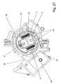
- a movable gate valve 23 is arranged.
- Fig. 25 is the Lock slide 23, if neither the key 3 nor the handle 4 in the recording is inserted, with recesses 44 on the pivot bearing 45 for the rotor 9 in engagement, that a rotation of the rotor 9 is locked.
- the locking slide 23 located in the rotor 9 has two compression springs 46. These compression springs 46 are pre-mounted on the locking slide 23. If the rotor 9 together with the additional locking slide 23 mounted in the ignition 1, so locks the gate valve 23 in the lateral recesses 44 of the cylinder front part 25 'on the pivot bearing 45 and prevents rotation of the rotor 9.
- the front part 53 of the key 3 has shown in FIG. 26 a corresponding to the inner contour of the locking slide 23 contour, wherein a on Front part 53 of the key 3 ab sap leverage web 47 of the locking slide 23 during insertion of the key 3 in the receptacle 5 due to the contour of the front part 53 of the key. 3 the locking slide 23 deflects laterally to solve the blocking function.
- the handle 4 has a front part 53 of the key 3 similar contour, has however, on both sides a groove 48, which is slightly wider than the web 47 on Locking slide 23.
- a groove 48 which is slightly wider than the web 47 on Locking slide 23.
- the invention is not limited to the described and illustrated embodiments limited. Rather, it also includes all professional training in the context of invention defined by the claims. So the invention can not only Ignition locks for any vehicle use, but also to other Locks, such as those on machines, real estate o. The like. Arranged are to be used.
Landscapes
- Engineering & Computer Science (AREA)
- Mechanical Engineering (AREA)
- Lock And Its Accessories (AREA)
Abstract
Description
- Fig. 1
- ein Zündschloß in perspektivischer Ansicht von der Vorderseite,
- Fig. 2
- das Zündschloß gemäß Fig. 1 von der Rückseite,
- Fig. 3
- einen Schnitt durch das Vorderteil des Zündschlosses mit eingesteckter Handhabe,
- Fig. 4
- einen Schnitt durch das Vorderteil des Zündschlosses mit eingestecktem Schlüssel,
- Fig. 5
- die Rückseite des Zündschlosses, wobei der Abziehschutz in vorfixierter Stellung befindlich ist,
- Fig. 6
- die Rückseite des Zündschlosses, wobei der Abziehschutz in verrasteter Endstellung befindlich ist,
- Fig. 7
- das Innere des Zündschlosses mit gesperrtem Shiftlock,
- Fig. 8
- das Innere des Zündschlosses mit freigegebenem Shiftlock,
- Fig. 9
- einen Detailausschnitt aus Fig. 7,
- Fig. 10
- einen Detailausschnitt aus Fig. 8,
- Fig. 11
- die im Zündschloß befindliche Leiterplatte mitsamt der Elektronik sowie darauf befindlichen Schaltern,
- Fig. 12
- einen Schnitt durch den Rotor, wobei kein Schlüssel in der Aufnahme befindlich ist,
- Fig. 13
- einen Schnitt durch den Rotor, wobei der Schlüssel in der Aufnahme befindlich ist,
- Fig. 14
- das Innere des Zündschlosses von der Rückseite, wobei kein Schlüssel in der Aufnahme befindlich ist,
- Fig. 15
- das Innere des Zündschlosses von der Rückseite, wobei der Schlüssel in der Aufnahme befindlich ist,
- Fig. 16
- das Innere des Zündschlosses wie in Fig. 14, wobei die Drehung des Rotors gesperrt ist,
- Fig. 17
- das Innere des Zündschlosses wie in Fig. 15, wobei die Drehung des Rotors freigegeben ist,
- Fig. 18
- einen Detailausschnitt aus dem Zündschloß mit eingesteckter Handhabe,
- Fig. 19
- einen Detailausschnitt aus dem Zündschloß mit gedrückter Handhabe,
- Fig. 20
- einen Detailausschnitt wie in Fig. 18, jedoch mit eingestecktem Schlüssel,
- Fig. 21
- das Innere des Zündschlosses mit gesperrter Drehsperre,
- Fig. 22
- das Innere des Zündschlosses mit freigegebener Drehsperre,
- Fig. 23
- einen Detailausschnitt aus dem Zündschloß entsprechend der Fig. 21,
- Fig. 24
- einen Detailausschnitt aus dem Zündschloß entsprechend der Fig. 22,
- Fig. 25
- den Rotor mit Sperrschieber, wobei weder die Handhabe noch der Schlüssel in der Aufnahme befindlich sind,
- Fig. 26
- den Rotor mit Sperrschieber, wobei der Schlüssel in der Aufnahme befindlich ist, und
- Fig. 27
- den Rotor mit Sperrschieber, wobei die Handhabe in der Aufnahme befindlich ist.
- 1:
- Zündschloß
- 2:
- Gehäuse
- 3:
- Schlüssel
- 4:
- Handhabe
- 5:
- Aufnahme (im Zündschloß)
- 6:
- Betätiger (von Handhabe)
- 7:
- Schaltelement / SAS-Schalter
- 8:
- Lichtleiter
- 9:
- Rotor
- 10:
- Steckanschluß
- 11:
- Stecker
- 12:
- Abziehschutz
- 13:
- Bowdenzug
- 14:
- Finger (am Bowdenzug)
- 15:
- Hebel
- 16:
- Kontur (am Rotor)
- 17:
- Druckfeder
- 18:
- Schalter / SSS-Schalter
- 19:
- Leiterplatte
- 20:
- (weiterer) Hebel
- 21:
- Druckfeder (an weiterem Hebel)
- 22:
- (rohrähnlicher) Zylinder
- 23:
- Rastschieberpaar / Sperrschieber
- 24:
- Aussparung
- 25:
- Zylinderhinterteil
- 25':
- Zylindervorderteil
- 26:
- Weckschalter
- 27:
- ELV-Schalter
- 28:
- (weiterer rohrähnlicher) Zylinder
- 29:
- Lichtschranke
- 30:
- (elektrisches / elektronisches) Bauelement
- 31:
- Unterseite (von Handhabe)
- 32:
- Stößel (an Handhabe)
- 33:
- Hülse
- 34:
- Feder
- 35:
- Betätigerteil
- 36:
- Hebel-Drehsperre
- 37:
- Hebel (von Hebel-Drehsperre)
- 38:
- Kontur (für Hebel-Drehsperre)
- 39:
- Zugankermagnet
- 40:
- Sperrklinke
- 41:
- Druckfeder (von Hebel-Drehsperre)
- 42:
- Druckfeder (von Zugankermagnet)
- 43:
- Sperrkante (an Kontur)
- 43':
- Sperrkante (an Hebel)
- 44:
- Aussparung
- 45:
- Drehlager (für Rotor)
- 46:
- Druckfeder (von Sperrschieber)
- 47:
- Steg (an Sperrschieber)
- 48:
- Nut (an Handhabe)
- 49:
- Elektronikmodul
- 50:
- Lagerstelle (von Hebel für SSS-Schalter)
- 51:
- Kragen (von Schlüssel)
- 52:
- Haltekragen (von Handhabe)
- 53:
- Vorderteil (von Schlüssel)
- 54:
- Steckerkragen
Claims (11)
- Zündschloß in einem Kraftfahrzeug, insbesondere für ein mit einem Schlüssel (3), wie einem elektronischen Schlüssel, einem Identifikations(ID)-Geber, einer Smartcard o. dgl., zur bedienungsunabhängigen Fahrberechtigung in der Art einer KeylessGo-Funktionalität und/oder zur bedienungsabhängigen Fahrberechtigung in der Art einer NonKeylessGo-Funktionalität zusammenwirkendes Zündschloßsystem, mit einem bewegbaren Rotor (9), mit einer im und/oder am Rotor (9) angeordneten Aufnahme (5) für den Schlüssel (3), wobei der Rotor (9) aus einer Ausgangsstellung in wenigstens eine Betätigungsstellung bewegbar ist, wobei der Rotor (9) in der Betätigungsstellung schaltend auf ein Schaltelement einwirkt, und wobei insbesondere zwischen dem Schlüssel (3) und dem Zündschloß (1) ein elektronischer Code austauschbar ist, so daß nach positiver Auswertung des Codes wenigstens eine vom Zündschloß (1) bewirkbare Funktion, wie das Einschalten von Verbrauchern im Kraftfahrzeug, das Starten des Kraftfahrzeugs o. dgl., freigegeben ist und/oder ausgelöst wird, dadurch gekennzeichnet, daß am Rotor (9) und/oder im Rotor (9) und/oder durch den Rotor (9) wenigstens eine Zündschloßfunktion, wie die Sperrung und/oder Freigabe des Schlüssels (3) im Zündschloß (1), die Betätigung eines Schalters (7) mittels des Schlüssels (3) im Zündschloß (1), die Sperrung und/oder Freigabe der Bewegung des Rotor (9) o. dgl., bewirkbar ist.
- Zündschloß nach Anspruch 1, dadurch gekennzeichnet, daß bei einem Kraftfahrzeug mit einem automatischen Getriebe lediglich in Stellung 'P' des Wählhebels für das Getriebe der Schlüssel (3) aus der Aufnahme (5) entnehmbar ist, daß vorzugsweise der Wählhebel des Getriebes mit einer Seite eines Bowdenzugs (13) verbunden ist, daß weiter vorzugsweise die andere Seite des Bowdenzugs (13) einen freistehenden Finger (14) aufweist, der in das Zündschloß (1) derart hineinragt, daß.über die Stellung des Wählhebels die Freigabe des Schlüssels (3) zur Entnahme aus der Aufnahme (5) gesteuert ist, und daß noch weiter vorzugsweise ein mit dem Finger (14) zusammenwirkender Hebel (15) zur Steuerung der Freigabe des Schlüssels (3) und/oder des Wählhebels von einer am Rotor (9) befindlichen Kontur (16) bewegt wird.
- Zündschloß nach Anspruch 1 oder 2, dadurch gekennzeichnet, daß eine Druckfeder (17) auf den Hebel (15) derart einwirkt, daß der Hebel (15) am Rotor (9), insbesondere an dessen Kontur (16), anliegt, daß vorzugsweise durch Drehung des Rotors (9) der Hebel (15) schwenkbar ist, daß weiter vorzugsweise der Finger (14) am Hebel (15) abstützbar und/oder der Hebel (15) durch den Finger (14) blockierbar ist, und daß noch weiter vorzugsweise das Drehlager (45) für den bewegbaren Rotor (9) in der Art eines Zylinders ausgebildet ist, insbesondere aus einem Zylindervorderteil (25') und einem Zylinderhinterteil (25) besteht.
- Zündschloß nach Anspruch 1, 2 oder 3, dadurch gekennzeichnet, daß bei Einführen des Schlüssels (3) in die Aufnahme (5) und/oder bei in der Aufnahme (5) befindlichen Schlüssel (3) ein elektrischer Schalter (18) betätigbar und/oder betätigt ist, daß vorzugsweise im Rotor (9) ein Hebel (20) befindlich ist, wobei der Hebel (20) sich mit dem Rotor (9) mitdreht, daß weiter vorzugsweise eine Seite des Hebels (20) in den Steckweg des Schlüssels (3) hineinreicht, und daß noch weiter vorzugsweise beim Stecken des Schlüssels (3) der Hebel (20) ausgelenkt wird, derart daß die andere Seite des Hebels (20) den Schalter (18) betätigt.
- Zündschloß nach einem der Ansprüche 1 bis 4, dadurch gekennzeichnet, daß der Hebel (20) mittels einer Druckfeder (21) derart belastet ist, daß der Hebel (20) in den Steckweg des Schlüssels (3) hineinreicht, daß vorzugsweise der Schalter (18) auf einer Leiterplatte (19) im Gehäuse (2) des Zündschlosses (1) befindlich ist, daß weiter vorzugsweise die andere Seite des Hebels (20) beim Erreichen der Endstellung des Schlüssels (3) in der Aufnahme (5) in einen rohrähnlichen Zylinder (22) am Rotor (9) einschwenkt, derart daß der Schalter (18) mittels des rohrähnlichen Zylinders (22) bei Bewegung des Rotors (9) betätigt wird, daß noch weiter vorzugsweise der Hebel (20) in ausgeschwenkter Stellung in eine Aussparung (24) im Zylinderhinterteil (25) ragt, daß nochmals weiter vorzugsweise der rohrähnliche Zylinder (22) weitere Schalter, wie einen Weckschalter (26) oder einen ELV-Schalter (27), betätigt, und daß abermals weiter vorzugsweise Lichtschranken (29) zur Detektierung verschiedener Drehzustände des Rotors (9) mittels eines weiteren rohrähnlichen Zylinders (28) am Rotor (9) steuerbar sind.
- Zündschloß nach einem der Ansprüche 1 bis 5, dadurch gekennzeichnet, daß in die Aufnahme (5) wahlweise der Schlüssel (3) oder eine Handhabe (4) zur Bedienung des Zündschlosses (1) einführbar ist, derart daß bei Betätigung der Handhabe (4) in der Ausgangsstellung des Rotors (9) schaltend auf einen im Zündschloß (1) befindlichen Schalter (7) eingewirkt wird, und daß vorzugsweise der zusätzliche Schalter (7) bei in der Aufnahme (5) befindlichen Schlüssel (3) dauernd sowie bei in der Aufnahme (5) befindlicher Handhabe (4) lediglich bei deren Betätigung geschaltet ist.
- Zündschloß nach einem der Ansprüche 1 bis 6, dadurch gekennzeichnet, daß die Handhabe (4) einen Betätiger (6) mit einem Stößel (32) aufweist, daß vorzugsweise die Handhabe (4) mittels des Stößels (32) bewegend auf eine Hülse (33) im Rotor (9) einwirkt, daß weiter vorzugsweise der Schlüssel (3) bei dessen Einstecken in die Aufnahme (5) die Hülse (33) direkt bewegt, und daß noch weiter vorzugsweise die Hülse (33) über ein Betätigerteil (35), das insbesondere mit einer Feder (34) versehen ist, den Schalter (7) betätigt.
- Zündschloß nach einem der Ansprüche 1 bis 7, dadurch gekennzeichnet, daß eine mechanische Sperre die Drehung des Rotors (9) lediglich nach positiver Auswertung des Codes freigibt, daß vorzugsweise die mechanische Sperre aus einer Hebel-Drehsperre (36) besteht, daß weiter vorzugsweise ein Hebel (37) der Hebel-Drehsperre (36) am Rotor (9) anliegt, daß noch weiter vorzugsweise der Rotor (9) eine Kontur (38) zum Auslenken des Hebels (37) aufweist, und daß nochmals weiter vorzugsweise mit dem einen Ende des Hebels (37) eine elektromagnetisch betätigbare Sperrklinke (40) der Hebel-Drehsperre (36) derart zusammenwirkt, daß der Hebel (37) zum Auslenken freigebbar ist und/oder das Auslenken des Hebels (37) gesperrt ist.
- Zündschloß nach einem der Ansprüche 1 bis 8, dadurch gekennzeichnet, daß der Hebel (37) mittels einer Druckfeder (41) am Rotor (9) angelegt ist, und daß vorzugsweise die Kontur (38) des Rotors (9) eine Sperrkante (43) aufweist, die insbesondere mit einer korrespondierenden Sperrkante (43') am Hebel (37) derart zusammenwirkt, daß die Bewegung des Rotors (9) sperrbar ist.
- Zündschloß nach einem der Ansprüche 1 bis 9, dadurch gekennzeichnet, daß in die Aufnahme (5) wahlweise der Schlüssel (3) oder eine Handhabe (4) zur Bedienung des Zündschlosses (1) einführbar ist, daß vorzugsweise das Drehlager (45) für den Rotor (9) in der Art eines Zylinders ausgebildet ist, daß weiter vorzugsweise im Rotor (9) ein beweglicher Sperrschieber (23) angeordnet ist, daß noch weiter vorzugsweise der Sperrschieber (23), wenn weder der Schlüssel (3) noch die Handhabe (4) in die Aufnahme (5) eingeführt ist, mit Aussparungen (44) am Drehlager (45) derart in Eingriff steht, daß eine Drehung des Rotors (9) gesperrt ist, daß nochmals weiter vorzugsweise der Sperrschieber (23), wenn der Schlüssel (3) in der Aufnahme (5) eingeführt ist, außer Eingriff mit den Aussparungen (44) am Drehlager (45) kommt, derart daß eine Drehung des Rotors (9) freigegeben ist, und daß abermals weiter vorzugsweise der Sperrschieber (23), wenn die Handhabe (4) in die Aufnahme (5) eingeführt ist, ebenfalls in Eingriff mit den Aussparungen (44) am Drehlager (45) kommt, derart daß eine Drehung des Rotors (9) gesperrt ist.
- Zündschloß nach einem der Ansprüche 1 bis 10, dadurch gekennzeichnet, daß der Sperrschieber (23) zwei vormontierte Druckfedern (46) aufweist, derart daß der Sperrschieber (23) bei dessen Montage in die Aussparung (44) am Drehlager (45) einrastet, daß vorzugsweise der Sperrschieber (23) einen Steg (47) aufweist, der beim Einstecken des Schlüssels (3) in die Aufnahme (5) sich am Vorderteil (53) des Schlüssels (3) derart abstützt, daß der Sperrschieber (23) zur Lösung der Sperrfunktion ausgelenkt wird, und daß weiter vorzugsweise die Handhabe (4) eine Nut (48) aufweist, in die der Steg (47) beim Einstecken der Handhabe (4) in die Aufnahme (5) eingreift, derart daß der Sperrschieber (23) in seiner die Sperrfunktion ausübenden Position bleibt.
Applications Claiming Priority (2)
| Application Number | Priority Date | Filing Date | Title |
|---|---|---|---|
| DE102004029743 | 2004-06-19 | ||
| DE102004029743 | 2004-06-19 |
Publications (2)
| Publication Number | Publication Date |
|---|---|
| EP1607289A1 true EP1607289A1 (de) | 2005-12-21 |
| EP1607289B1 EP1607289B1 (de) | 2013-05-22 |
Family
ID=34937519
Family Applications (1)
| Application Number | Title | Priority Date | Filing Date |
|---|---|---|---|
| EP05013106.9A Expired - Lifetime EP1607289B1 (de) | 2004-06-19 | 2005-06-17 | Zündschloss für ein Kraftfahrzeug |
Country Status (1)
| Country | Link |
|---|---|
| EP (1) | EP1607289B1 (de) |
Cited By (5)
| Publication number | Priority date | Publication date | Assignee | Title |
|---|---|---|---|---|
| DE102005062683A1 (de) * | 2005-12-23 | 2007-07-05 | Daimlerchrysler Ag | Fahrberechtigungssystem für ein Kraftfahrzeug |
| DE102005062686A1 (de) * | 2005-12-23 | 2007-07-05 | Daimlerchrysler Ag | Fahrberechtigungssystem für ein Kraftfahrzeug |
| ITTO20110402A1 (it) * | 2011-05-06 | 2012-11-07 | Giobert Spa | Lettore di chiave elettronica di un veicolo |
| DE102006000869B4 (de) * | 2006-01-05 | 2013-04-18 | Leopold Kostal Gmbh & Co. Kg | Elektronischer Zündanlassschalter |
| WO2013085844A1 (en) * | 2011-12-09 | 2013-06-13 | Chrysler Group Llc | Ignition module |
Citations (7)
| Publication number | Priority date | Publication date | Assignee | Title |
|---|---|---|---|---|
| DE4434587A1 (de) * | 1993-10-01 | 1995-04-06 | Marquardt Gmbh | Elektronisches Zündstartschloßsystem an einem Kraftfahrzeug |
| DE10150708A1 (de) * | 2001-10-13 | 2003-04-17 | Delphi Tech Inc | Zündschloss |
| JP2004058880A (ja) * | 2002-07-30 | 2004-02-26 | Honda Lock Mfg Co Ltd | 車両用ステアリングロック装置 |
| JP2004058881A (ja) * | 2002-07-30 | 2004-02-26 | Honda Lock Mfg Co Ltd | 車両用ステアリングロック装置 |
| JP2004060316A (ja) * | 2002-07-30 | 2004-02-26 | Honda Lock Mfg Co Ltd | 車両用ステアリングロック装置 |
| WO2004028871A2 (de) * | 2002-09-18 | 2004-04-08 | Daimlerchrysler Ag | Fahrberechtigungssystem |
| US20040129041A1 (en) * | 2002-07-30 | 2004-07-08 | Katsuyoshi Shigeyama | Steerage locking system for vehicle |
Family Cites Families (1)
| Publication number | Priority date | Publication date | Assignee | Title |
|---|---|---|---|---|
| JP3545646B2 (ja) * | 1999-06-11 | 2004-07-21 | 株式会社アルファ | ロック装置 |
-
2005
- 2005-06-17 EP EP05013106.9A patent/EP1607289B1/de not_active Expired - Lifetime
Patent Citations (7)
| Publication number | Priority date | Publication date | Assignee | Title |
|---|---|---|---|---|
| DE4434587A1 (de) * | 1993-10-01 | 1995-04-06 | Marquardt Gmbh | Elektronisches Zündstartschloßsystem an einem Kraftfahrzeug |
| DE10150708A1 (de) * | 2001-10-13 | 2003-04-17 | Delphi Tech Inc | Zündschloss |
| JP2004058880A (ja) * | 2002-07-30 | 2004-02-26 | Honda Lock Mfg Co Ltd | 車両用ステアリングロック装置 |
| JP2004058881A (ja) * | 2002-07-30 | 2004-02-26 | Honda Lock Mfg Co Ltd | 車両用ステアリングロック装置 |
| JP2004060316A (ja) * | 2002-07-30 | 2004-02-26 | Honda Lock Mfg Co Ltd | 車両用ステアリングロック装置 |
| US20040129041A1 (en) * | 2002-07-30 | 2004-07-08 | Katsuyoshi Shigeyama | Steerage locking system for vehicle |
| WO2004028871A2 (de) * | 2002-09-18 | 2004-04-08 | Daimlerchrysler Ag | Fahrberechtigungssystem |
Non-Patent Citations (1)
| Title |
|---|
| PATENT ABSTRACTS OF JAPAN vol. 2003, no. 12 5 December 2003 (2003-12-05) * |
Cited By (6)
| Publication number | Priority date | Publication date | Assignee | Title |
|---|---|---|---|---|
| DE102005062683A1 (de) * | 2005-12-23 | 2007-07-05 | Daimlerchrysler Ag | Fahrberechtigungssystem für ein Kraftfahrzeug |
| DE102005062686A1 (de) * | 2005-12-23 | 2007-07-05 | Daimlerchrysler Ag | Fahrberechtigungssystem für ein Kraftfahrzeug |
| DE102006000869B4 (de) * | 2006-01-05 | 2013-04-18 | Leopold Kostal Gmbh & Co. Kg | Elektronischer Zündanlassschalter |
| ITTO20110402A1 (it) * | 2011-05-06 | 2012-11-07 | Giobert Spa | Lettore di chiave elettronica di un veicolo |
| WO2013085844A1 (en) * | 2011-12-09 | 2013-06-13 | Chrysler Group Llc | Ignition module |
| US9228558B2 (en) | 2011-12-09 | 2016-01-05 | Fca Us Llc | Ignition module |
Also Published As
| Publication number | Publication date |
|---|---|
| EP1607289B1 (de) | 2013-05-22 |
Similar Documents
| Publication | Publication Date | Title |
|---|---|---|
| DE19939733C2 (de) | Vorrichtung zum Starten eines Fahrzeugmotors mittels eines elektronischen Schlüssels | |
| EP1279576B1 (de) | Zündschlosssystem für ein Kraftfahrzeug | |
| EP1737713B1 (de) | Vorrichtung zum starten eines fahrzeugmotors mittels eines elektronischen schlüssels und ein dazu zu verwendender schlüssel | |
| EP1135284B1 (de) | Schliessystem, insbesondere für kraftfahrzeuge | |
| EP1384633A1 (de) | Schliesssystem für Motorfahrzeuge | |
| EP1419944B1 (de) | Zündschlosssystem für ein Kraftfahrzeug | |
| EP0999968B2 (de) | Lenkradverriegelung an einem kraftfahrzeug | |
| DE102004013198A1 (de) | Zündschloßsystem für ein Kraftfahrzeug | |
| WO2015181400A1 (de) | Schliesszylinder mit rückstellsperre | |
| EP0926024B1 (de) | Schliesssystem, insbesondere für Kraftfahrzeuge | |
| EP1607289B1 (de) | Zündschloss für ein Kraftfahrzeug | |
| EP1128997A1 (de) | Fahrberechtigungssystem und entsprechendes betriebsverfahren, insbesondere für kraftfahrzeuge | |
| EP1029756B1 (de) | Elektronisches Zündstartschlosssystem für ein Kraftfahrzeug | |
| DE10107992B4 (de) | Zündschloßsystem für ein Kraftfahrzeug | |
| DE19921889B4 (de) | Zündschloß für ein Kraftfahrzeug | |
| DE19838992C2 (de) | Zündanlaßschalter für Kraftfahrzeuge mit elektronischer Lenkungsverriegelung | |
| DE102005028097A1 (de) | Zündschloß für ein Kraftfahrzeug | |
| DE102005028156A1 (de) | Elektrisches Bauteil | |
| DE19847391A1 (de) | Steuervorrichtung für Zündung und Lenkungsverriegelung eines Kraftfahrzeugs | |
| DE10106123B4 (de) | Elektrisches/elektronisches Schaltsystem für Kraftfahrzeuge | |
| DE102008051366B4 (de) | Zündstartsystem | |
| EP1771322B1 (de) | Vorrichtung zum zünden und/oder anlassen des motors in einem kraftfahrzeug | |
| EP0913547B1 (de) | Schliesssystem, insbesondere für Kraftfahrzeuge | |
| DE19733448B4 (de) | Start/Stoppeinrichtung für eine schlüssellose Betätigung der Zündung | |
| DE102010061192A1 (de) | Mechanische Verriegelungsvorrichtung für ein Motorrad |
Legal Events
| Date | Code | Title | Description |
|---|---|---|---|
| PUAI | Public reference made under article 153(3) epc to a published international application that has entered the european phase |
Free format text: ORIGINAL CODE: 0009012 |
|
| AK | Designated contracting states |
Kind code of ref document: A1 Designated state(s): AT BE BG CH CY CZ DE DK EE ES FI FR GB GR HU IE IS IT LI LT LU MC NL PL PT RO SE SI SK TR |
|
| AX | Request for extension of the european patent |
Extension state: AL BA HR LV MK YU |
|
| 17P | Request for examination filed |
Effective date: 20060307 |
|
| AKX | Designation fees paid |
Designated state(s): AT BE BG CH CY CZ DE DK EE ES FI FR GB GR HU IE IS IT LI LT LU MC NL PL PT RO SE SI SK TR |
|
| 17Q | First examination report despatched |
Effective date: 20080521 |
|
| GRAP | Despatch of communication of intention to grant a patent |
Free format text: ORIGINAL CODE: EPIDOSNIGR1 |
|
| GRAS | Grant fee paid |
Free format text: ORIGINAL CODE: EPIDOSNIGR3 |
|
| GRAA | (expected) grant |
Free format text: ORIGINAL CODE: 0009210 |
|
| AK | Designated contracting states |
Kind code of ref document: B1 Designated state(s): AT BE BG CH CY CZ DE DK EE ES FI FR GB GR HU IE IS IT LI LT LU MC NL PL PT RO SE SI SK TR |
|
| REG | Reference to a national code |
Ref country code: GB Ref legal event code: FG4D Free format text: NOT ENGLISH |
|
| REG | Reference to a national code |
Ref country code: CH Ref legal event code: EP |
|
| REG | Reference to a national code |
Ref country code: AT Ref legal event code: REF Ref document number: 613043 Country of ref document: AT Kind code of ref document: T Effective date: 20130615 |
|
| REG | Reference to a national code |
Ref country code: IE Ref legal event code: FG4D Free format text: LANGUAGE OF EP DOCUMENT: GERMAN |
|
| REG | Reference to a national code |
Ref country code: DE Ref legal event code: R096 Ref document number: 502005013718 Country of ref document: DE Effective date: 20130718 |
|
| REG | Reference to a national code |
Ref country code: LT Ref legal event code: MG4D |
|
| PG25 | Lapsed in a contracting state [announced via postgrant information from national office to epo] |
Ref country code: PT Free format text: LAPSE BECAUSE OF FAILURE TO SUBMIT A TRANSLATION OF THE DESCRIPTION OR TO PAY THE FEE WITHIN THE PRESCRIBED TIME-LIMIT Effective date: 20130923 Ref country code: ES Free format text: LAPSE BECAUSE OF FAILURE TO SUBMIT A TRANSLATION OF THE DESCRIPTION OR TO PAY THE FEE WITHIN THE PRESCRIBED TIME-LIMIT Effective date: 20130902 Ref country code: LT Free format text: LAPSE BECAUSE OF FAILURE TO SUBMIT A TRANSLATION OF THE DESCRIPTION OR TO PAY THE FEE WITHIN THE PRESCRIBED TIME-LIMIT Effective date: 20130522 Ref country code: SE Free format text: LAPSE BECAUSE OF FAILURE TO SUBMIT A TRANSLATION OF THE DESCRIPTION OR TO PAY THE FEE WITHIN THE PRESCRIBED TIME-LIMIT Effective date: 20130522 Ref country code: GR Free format text: LAPSE BECAUSE OF FAILURE TO SUBMIT A TRANSLATION OF THE DESCRIPTION OR TO PAY THE FEE WITHIN THE PRESCRIBED TIME-LIMIT Effective date: 20130823 Ref country code: FI Free format text: LAPSE BECAUSE OF FAILURE TO SUBMIT A TRANSLATION OF THE DESCRIPTION OR TO PAY THE FEE WITHIN THE PRESCRIBED TIME-LIMIT Effective date: 20130522 Ref country code: SI Free format text: LAPSE BECAUSE OF FAILURE TO SUBMIT A TRANSLATION OF THE DESCRIPTION OR TO PAY THE FEE WITHIN THE PRESCRIBED TIME-LIMIT Effective date: 20130522 Ref country code: IS Free format text: LAPSE BECAUSE OF FAILURE TO SUBMIT A TRANSLATION OF THE DESCRIPTION OR TO PAY THE FEE WITHIN THE PRESCRIBED TIME-LIMIT Effective date: 20130922 |
|
| REG | Reference to a national code |
Ref country code: NL Ref legal event code: VDEP Effective date: 20130522 |
|
| PG25 | Lapsed in a contracting state [announced via postgrant information from national office to epo] |
Ref country code: PL Free format text: LAPSE BECAUSE OF FAILURE TO SUBMIT A TRANSLATION OF THE DESCRIPTION OR TO PAY THE FEE WITHIN THE PRESCRIBED TIME-LIMIT Effective date: 20130522 Ref country code: BG Free format text: LAPSE BECAUSE OF FAILURE TO SUBMIT A TRANSLATION OF THE DESCRIPTION OR TO PAY THE FEE WITHIN THE PRESCRIBED TIME-LIMIT Effective date: 20130822 |
|
| BERE | Be: lapsed |
Owner name: MARQUARDT G.M.B.H. Effective date: 20130630 |
|
| PG25 | Lapsed in a contracting state [announced via postgrant information from national office to epo] |
Ref country code: DK Free format text: LAPSE BECAUSE OF FAILURE TO SUBMIT A TRANSLATION OF THE DESCRIPTION OR TO PAY THE FEE WITHIN THE PRESCRIBED TIME-LIMIT Effective date: 20130522 Ref country code: EE Free format text: LAPSE BECAUSE OF FAILURE TO SUBMIT A TRANSLATION OF THE DESCRIPTION OR TO PAY THE FEE WITHIN THE PRESCRIBED TIME-LIMIT Effective date: 20130522 Ref country code: SK Free format text: LAPSE BECAUSE OF FAILURE TO SUBMIT A TRANSLATION OF THE DESCRIPTION OR TO PAY THE FEE WITHIN THE PRESCRIBED TIME-LIMIT Effective date: 20130522 Ref country code: CZ Free format text: LAPSE BECAUSE OF FAILURE TO SUBMIT A TRANSLATION OF THE DESCRIPTION OR TO PAY THE FEE WITHIN THE PRESCRIBED TIME-LIMIT Effective date: 20130522 |
|
| REG | Reference to a national code |
Ref country code: CH Ref legal event code: PL |
|
| PG25 | Lapsed in a contracting state [announced via postgrant information from national office to epo] |
Ref country code: RO Free format text: LAPSE BECAUSE OF FAILURE TO SUBMIT A TRANSLATION OF THE DESCRIPTION OR TO PAY THE FEE WITHIN THE PRESCRIBED TIME-LIMIT Effective date: 20130522 Ref country code: NL Free format text: LAPSE BECAUSE OF FAILURE TO SUBMIT A TRANSLATION OF THE DESCRIPTION OR TO PAY THE FEE WITHIN THE PRESCRIBED TIME-LIMIT Effective date: 20130522 Ref country code: IT Free format text: LAPSE BECAUSE OF FAILURE TO SUBMIT A TRANSLATION OF THE DESCRIPTION OR TO PAY THE FEE WITHIN THE PRESCRIBED TIME-LIMIT Effective date: 20130522 Ref country code: MC Free format text: LAPSE BECAUSE OF FAILURE TO SUBMIT A TRANSLATION OF THE DESCRIPTION OR TO PAY THE FEE WITHIN THE PRESCRIBED TIME-LIMIT Effective date: 20130522 |
|
| REG | Reference to a national code |
Ref country code: IE Ref legal event code: MM4A |
|
| PLBE | No opposition filed within time limit |
Free format text: ORIGINAL CODE: 0009261 |
|
| REG | Reference to a national code |
Ref country code: FR Ref legal event code: ST Effective date: 20140228 |
|
| STAA | Information on the status of an ep patent application or granted ep patent |
Free format text: STATUS: NO OPPOSITION FILED WITHIN TIME LIMIT |
|
| PG25 | Lapsed in a contracting state [announced via postgrant information from national office to epo] |
Ref country code: BE Free format text: LAPSE BECAUSE OF NON-PAYMENT OF DUE FEES Effective date: 20130630 |
|
| GBPC | Gb: european patent ceased through non-payment of renewal fee |
Effective date: 20130822 |
|
| 26N | No opposition filed |
Effective date: 20140225 |
|
| PG25 | Lapsed in a contracting state [announced via postgrant information from national office to epo] |
Ref country code: LI Free format text: LAPSE BECAUSE OF NON-PAYMENT OF DUE FEES Effective date: 20130630 Ref country code: IE Free format text: LAPSE BECAUSE OF NON-PAYMENT OF DUE FEES Effective date: 20130617 Ref country code: CH Free format text: LAPSE BECAUSE OF NON-PAYMENT OF DUE FEES Effective date: 20130630 |
|
| PG25 | Lapsed in a contracting state [announced via postgrant information from national office to epo] |
Ref country code: FR Free format text: LAPSE BECAUSE OF NON-PAYMENT OF DUE FEES Effective date: 20130722 |
|
| REG | Reference to a national code |
Ref country code: DE Ref legal event code: R097 Ref document number: 502005013718 Country of ref document: DE Effective date: 20140225 |
|
| PG25 | Lapsed in a contracting state [announced via postgrant information from national office to epo] |
Ref country code: GB Free format text: LAPSE BECAUSE OF NON-PAYMENT OF DUE FEES Effective date: 20130822 |
|
| REG | Reference to a national code |
Ref country code: AT Ref legal event code: MM01 Ref document number: 613043 Country of ref document: AT Kind code of ref document: T Effective date: 20130617 |
|
| PG25 | Lapsed in a contracting state [announced via postgrant information from national office to epo] |
Ref country code: AT Free format text: LAPSE BECAUSE OF NON-PAYMENT OF DUE FEES Effective date: 20130617 |
|
| PG25 | Lapsed in a contracting state [announced via postgrant information from national office to epo] |
Ref country code: CY Free format text: LAPSE BECAUSE OF FAILURE TO SUBMIT A TRANSLATION OF THE DESCRIPTION OR TO PAY THE FEE WITHIN THE PRESCRIBED TIME-LIMIT Effective date: 20130522 Ref country code: TR Free format text: LAPSE BECAUSE OF FAILURE TO SUBMIT A TRANSLATION OF THE DESCRIPTION OR TO PAY THE FEE WITHIN THE PRESCRIBED TIME-LIMIT Effective date: 20130522 |
|
| PG25 | Lapsed in a contracting state [announced via postgrant information from national office to epo] |
Ref country code: HU Free format text: LAPSE BECAUSE OF FAILURE TO SUBMIT A TRANSLATION OF THE DESCRIPTION OR TO PAY THE FEE WITHIN THE PRESCRIBED TIME-LIMIT; INVALID AB INITIO Effective date: 20050617 Ref country code: LU Free format text: LAPSE BECAUSE OF NON-PAYMENT OF DUE FEES Effective date: 20130617 |
|
| REG | Reference to a national code |
Ref country code: DE Ref legal event code: R082 Ref document number: 502005013718 Country of ref document: DE Representative=s name: PATENTANWAELTE STAEGER & SPERLING PARTNERSCHAF, DE Ref country code: DE Ref legal event code: R082 Ref document number: 502005013718 Country of ref document: DE Representative=s name: JOSTARNDT PATENTANWALTS-AG, DE |
|
| REG | Reference to a national code |
Ref country code: DE Ref legal event code: R082 Ref document number: 502005013718 Country of ref document: DE Representative=s name: PATENTANWAELTE STAEGER & SPERLING PARTNERSCHAF, DE Ref country code: DE Ref legal event code: R082 Ref document number: 502005013718 Country of ref document: DE |
|
| REG | Reference to a national code |
Ref country code: DE Ref legal event code: R082 Ref document number: 502005013718 Country of ref document: DE Representative=s name: PATENTANWAELTE STAEGER & SPERLING PARTNERSCHAF, DE |
|
| P01 | Opt-out of the competence of the unified patent court (upc) registered |
Effective date: 20230522 |
|
| PGFP | Annual fee paid to national office [announced via postgrant information from national office to epo] |
Ref country code: DE Payment date: 20240617 Year of fee payment: 20 |
|
| REG | Reference to a national code |
Ref country code: DE Ref legal event code: R071 Ref document number: 502005013718 Country of ref document: DE |