EP1607193A2 - Méthode et dispositif pour évaluer l'état d'au moins une articulation de robot - Google Patents
Méthode et dispositif pour évaluer l'état d'au moins une articulation de robot Download PDFInfo
- Publication number
- EP1607193A2 EP1607193A2 EP05010720A EP05010720A EP1607193A2 EP 1607193 A2 EP1607193 A2 EP 1607193A2 EP 05010720 A EP05010720 A EP 05010720A EP 05010720 A EP05010720 A EP 05010720A EP 1607193 A2 EP1607193 A2 EP 1607193A2
- Authority
- EP
- European Patent Office
- Prior art keywords
- robot
- data
- evaluation
- state
- determined
- Prior art date
- Legal status (The legal status is an assumption and is not a legal conclusion. Google has not performed a legal analysis and makes no representation as to the accuracy of the status listed.)
- Ceased
Links
Images


Classifications
-
- B—PERFORMING OPERATIONS; TRANSPORTING
- B25—HAND TOOLS; PORTABLE POWER-DRIVEN TOOLS; MANIPULATORS
- B25J—MANIPULATORS; CHAMBERS PROVIDED WITH MANIPULATION DEVICES
- B25J9/00—Programme-controlled manipulators
- B25J9/16—Programme controls
- B25J9/1628—Programme controls characterised by the control loop
- B25J9/1641—Programme controls characterised by the control loop compensation for backlash, friction, compliance, elasticity in the joints
Definitions
- the invention relates to a method and a system for condition assessment of at least an axle joint of an industrial robot.
- the time interval between two maintenance times is usually defined due to a certain number of operating hours for the robot. An individual view the actual tasks or work performed by the industrial robot does not take place.
- a method and a system for assessing the status of at least one axle joint of an industrial robot indicate the actual work performed by the industrial robot be taken into account.
- the inventive method for condition assessment of at least an axle joint of an industrial robot the following steps on. Based on data of an existing mechanical game on the at least one axle joint of the industrial robot becomes a state of wear of the determined at least one axle joint. Based on data of a torque curve on the at least one pivot joint during at least a first Work cycle of the industrial robot will be a first load condition of at least determined an axle joint. Furthermore, on the basis of data of a movement process on the at least one pivot joint during at least a second Working cycle of the industrial robot determines a second load condition. Finally, the assessment of the condition by pre-evaluation of the state of wear, the first and second loading conditions and subsequent comparison performed with an empirically obtained comparison matrix.
- the inventive method operates on the basis of real measured or determined data of the industrial robot during its working cycles.
- data basis It serves the mechanical game, the torque curve and the Motion sequence of the robot.
- the result of the condition evaluation can be in one simple case in the statement that the at least one knuckle still within permissible parameters works or not.
- this statement can be more differentiated specified, for example, up to the indication of periods within for example, the axle joint may still be operated without maintenance.
- An advantageous embodiment of the method according to the invention is characterized in that in that a load delivery device has a first, with a second robot axis leg movably connected to each other by an axle joint in one direction of rotation, with a robot arm connected to the free end of a robot arm in a measurement line is alternately applied with a predetermined force that a Displacement sensor, the deflection of the first Roboterachsschenkels in a given Distance to the axis of rotation of the axle joint measures, and that connected to the distance sensor Evaluation device taking into account the geometric arrangement data in the measurement of the displacement sensor and the industrial robot as well as the measured Deflection a twist angle of the first robot arm leg as a measure of an existing Game calculated at the knuckle joint.
- the object is achieved by the system according to the invention for condition assessment at least one axle joint of a robot arm of an industrial robot with a data module containing the data of an existing mechanical game, a torque curve and a sequence of movements at least one Achsgelenk contains during at least one working cycle of the industrial robot, with an analysis module, with which on the basis of the data load conditions and / or wear conditions can be determined, and with an evaluation module, by which is an evaluation of the determined conditions, in particular by preliminary evaluation the state of wear, the first and the second load condition and then Comparison with an empirically obtained comparison matrix enabled is.
- the data module thus contains real data of the mechanical play of the torque curve as well as the movement sequence, which can then be analyzed with the analysis module are.
- an assessment module it is possible for an assessment module to analyze those Data used as the basis for a condition assessment.
- the evaluation statements made are therefore based on real burdens or real Wear conditions met.
- a cheap valuation option consists of the respectively found states, ie the state of wear, the first and second loading conditions to compare with reference values. These reference values are, for example, in a so-called comparison value matrix and their values were found empirically.
- the comparison value matrix Contains, for example, a common value that can be compared with a common state value of all three states, or three different ones Value groups, each of the comparison values to a state, ie the Wear state, the first or the second load state associated.
- Data module In an advantageous compact embodiment of the system according to the invention are Data module, the analysis module and the evaluation module in the robot controller arranged.
- the individual modules Distribute devices. This offers, for example, an evaluation in the form of a Measuring computer, or existing evaluation devices within a process control Network, as often used for overall control of robotic systems.
- Fig. 1 shows an overview 5 of the inventive method for condition assessment from pivot joints to robots.
- There are three main steps of the inventive method which determine the individual states, in a first Graph 7 for the determination of a first load state, a second graph 9 for determining a state of wear and a third graph 11 for the determination a second load condition shown.
- To symbolize another Process step 13 of the process according to the invention is a schematic used text box shown that indicates by means of arrows 15 that in this process step Accessing certain data or determined state values is, and used to assess the state of the at least one pivot joint become.
- Graph 7 shows the representation of torque curves of three different Robot axes.
- the ordinate axis of the graph is called the torque axis, normalized to a maximum value corresponding to a percentage load of 100%, applied so that the different axes of the robot also comparable can be represented in a graph.
- the different ones Axes of the robot according to their design, their drive, their performance, theirs Gearbox and so on designed completely different, so that an order in absolute values possible, but would be very confusing and at least to one would lead to unfavorable presentation.
- the first Torque curve has a first location and a second location, on which the band will leave.
- the evaluation of a current axle wear can be made on the basis of different criteria.
- Another possibility of the evaluation is the number of opposing ones Maximum values when approaching a coordinate within a work cycle as a benchmark for wear estimation.
- One more option consists of a trend comparison of the values of the friction of a power unit, ie in particular Motor, gearbox and robotic arm, within a movement of one coordinate within the working cycle of the robot to look at a second coordinate.
- a power unit ie in particular Motor, gearbox and robotic arm
- Graph 9 shows the example of a weighted Achsspielteil based on a Ausensegrafik.
- Rated Achsspielflop means that direct or filtered, ie in of any form selects or prepares readings in addition to a particular one Factor are weighted.
- a first pillar corresponds to a maximum play at 100%.
- a value can be set at which, according to experience, a limit has been reached, in which an actually existing wear the operation of the Restricts or even disturbs robot. In the figure, this is through a second column, the has a height of 60%, shown.
- An actually measured Achsspiel as well its rating is represented by a third pillar, which is approximately 40%.
- a fourth pillar is shown, which is an already existing first game at represents a new robot.
- the graphic 11 shows a graphical representation of the data on the basis of the numerical example according to the table 110 according to FIG. 7.
- a second table is shown whose first column in the table contains the same information as the first column.
- the second table column and the third table column where their contents correspond to those of the second column and the third column.
- the contents of this table are prepared in a pie-shaped graphic and provided with an index of the segments shown in color, for example the cake graphic features an axis name.
- Procedure means that the state of wear, the first and the second load condition are each provided with individual weighting factors, so that the determined states are in a certain relation to each other.
- a common evaluation of all states should be made on this basis be carried out so that by means of a mathematical summation of pre-evaluated individual states found a value for the weighted overall state becomes.
- This common value is now compared to a comparison value matrix, the empirically for this particular robot type and for the respective axle joint empirically was determined. The result of the comparison is a qualitative or quantitative statement about the condition of the respective axle joint.
- a simple statement about the condition of an axle joint would be, for example, that certain maintenance work must be performed.
- a recommendation is made, after how many additional operating hours maintenance work and, if necessary, which, are to be carried out.
- a recommendation about how the robot's motion program changed would have to be the load of certain axle joints, especially those that are particularly frequently moved or otherwise exposed to special stress, should be changed to other axle joints, which are less loaded, stronger burdening, so the overall a more balanced, evenly distributed burden to reach all axle joints.
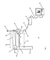
- FIG. 2 shows an example of a first measuring arrangement 10 for transmission clearance measurement a multi-axis robot.
- an axle joint 2 is shown schematically, which a first 4 and a second Roboterachsschenkel 6 rotatably about a other axis 8 connects.
- the first robot axis leg 4 represent the free end of the robot arm, while the second robot axis leg 6 by means of other axle joints and other Roboterachsschenkel, the but not shown here are connected to the robot's foot, which in turn stuck connected to a foundation.
- a holding bar 12 is with its first end 14 on the second robot axis leg R6 firmly connected.
- the junction is from the axis of rotation 8 with a specific Distance appropriate.
- a displacement sensor 18 is arranged and so aligned, that the path measurement runs exactly in the picture plane and also, as in shown in this image, exactly perpendicular to the longitudinal orientation of the first robot axis leg 4 in its starting position for the low-clearance measurement.
- the first 4 and second robot axis legs 6 form a right angle to each other. In this arrangement, therefore, the retaining bar 12 runs exactly parallel to the starting position of the first robot knuckle 4.
- connection device 20 In the vicinity of the free end of the first Roboterachsschenkels 4 is a connection device 20 attached. At the connecting device 20 engages one in this Figure lifting device not shown, and alternately brings a previously defined Force as load in the direction indicated in the image with the first part 22.
- the load lifting device itself is not shown in this figure, but should be symbolic the effects, ie the applied force on the first robot axis leg 4 through the connecting lines between the connecting device 20 and two accordingly arranged Eckkraftmessinstrumente 24 may be indicated.
- the force of tensile forces such as attacking ropes, at first Robot Axle Applied.
- the distance of a Bringungscons the force to the axis of rotation 8 here as the first distance 26th indicates due to the generated leverage or the moment on the axle joint 2, depending on the applied force must be selected.
- the applied force is preferably selected so that on the one hand a transmission of the Achsgelenk 2, depending on the direction of force, each in its end positions according to the On the other hand, the measurement for counterfeit deformation is brought of the first Roboterachsschenkels 4 is avoided.
- a deflection position 28 as a dotted outline of the first Roboterachsschenkels R2 shown in a maximum deflection position, in the case that the applied force by the load lifting device in the straight with the second Arrow 30 indicated direction is applied.
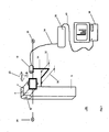
- the displacement sensor 18 is connected to a measuring transducer 36 by means of a measuring line 34.
- the transducer has several functions.
- the displacement sensor 18 is an analog signal generator, so that the transducer 36, inter alia, the Task has to transform that analog signal into a digital output signal and to provide such an evaluation device.
- the output device a measuring computer 38 by means of a second measuring line 40 to the output of Measuring transducer 36 connected.
- the second measuring line can already have a data connection line be, for example, in the case that the transducer 36 also a measuring computer is and the output data ready for a prescribed or otherwise prepared as defined data protocol.
- transducer 36 is then universally applicable and so different bus systems or different displacement sensors can be connected to the transducer, without that this device would have to be changed structurally.
- a Such arrangement allows a very flexible structure of the evaluation as such.
- the feeding of the output signal the transducer 36 in a control system or in a measuring system possible, that, for example, even further away in a control room or even via data line or appropriate coupling via telecom lines and the Internet in principle Communicable to any point of view worldwide.
- the load bearing device acts on the first Roboterachsschenkel 4 initially with a force in one of the directions as indicated in one of the first arrows 22. by virtue of the force is the first Roboterachsschenkel 4 now from its load-free Position deflected and slightly shifted in the pulling direction of the force.
- Force gauge 24 which is arranged on the side of the attacking force is the Force constantly measured and the load device in this way to a maximum amount limited, in which the dynamometer feedback to the load bearing device about the currently prevailing load on the first robot arm 4 reports.
- the process of deflection is detected by the distance sensor 18 in terms of distance.
- the Wegserisor is an ultrasonic sensor, which is also small Track differences detected with sufficient accuracy.
- the displacement sensor 18 is through the holding bar 12 rigidly connected to the second robot axis leg 6.
- the first End 14 is spaced from the axis of rotation 8 at a first distance 42.
- a second distance 44 predetermined by the length of the support rod 12, so that the Position of the displacement sensor 18 can be determined exactly.
- the load bearing device receives the predetermined load on the first robot arm leg 4 Now stand upright for a moment while the measurement is constantly made becomes. After a certain time, the first Roboterachsschenkel is relieved again and the load lifting device now brings a force in the exact opposite direction as before on the first Roboterachsschenkel 4. The deflection is thus now in exactly the opposite direction. This process is also carried out by the displacement sensor 18 recorded. As before, here is the force actually applied detected by the second force measuring device 24 and to a predetermined maximum limited.
- the data acquired by the displacement sensor 18 are passed on to the transducer 36, the received analog signals from the displacement sensor 18 in digital from the measuring computer Converts 38 usable signals.
- the measuring computer 38 now calculates on the basis of the geometric arrangement data and the measured values of the displacement sensor, ie the measured deflection in both of the Directions in which the first Roboterachsschenkel 4 was charged, an actually existing Play on the Achsgelenk 2 due to the selected in this example load direction is the calculated game the gear game, so the game that in the direction of rotation of the axle joint 2 is present.
- the consideration of geometric Arrangement data in the Fig. 3 explained in more detail.
- the displacement sensor 18 is aligned exactly on a measuring line, the expected deflection directions of the Roboterachsschenkels corresponds and due the skillful choice of force application directions exactly tangential to the directions of rotation the axis of rotation 8 of the axle joint 2 is aligned.
- Possible errors in the orientation of the displacement sensor 18, so an angle error in the alignment with respect to the measurement line and the direction the deflection of the first Roboterachsschenkels 4 can also from the evaluation by means of the corresponding measurement of the geometrical arrangement data be compensated for the displacement sensor.
- FIG. 3 shows a second measuring arrangement, which is constructed similarly to the first measuring arrangement, which is why the same reference numerals as in FIG. 1 can be used.
- FIG. 2 shows a clearance measurement of the bearing clearance on Achsgelenk, that is, that the measuring directions along the measuring line of the displacement sensor exactly parallel to the axis of rotation of the axle joint, and exactly in a third Distance, which is the clearance between the distance sensor and the Rotary axis corresponds.
- the displacement sensor in this figure is held in position by a second holding rod, one end of which in turn is attached to the second robot axis leg and whose second end is connected to the sensor, wherein, in contrast to Figure 1 the second holding bar by two spatial direction changes the desired positioning allows the displacement sensor in all three directions. It can by a first portion of the second support rod, which with the second robot axis leg is connected, the distance of the displacement sensor to the first Roboterachsschenkel namely in the direction of the axis of rotation to be adjusted. By means of a second section, which has the third distance as the length, the clear distance between set the displacement sensor and the axis of rotation.
- the load bearing device picks up along a parallel line to the axis of rotation at the first robot axis joint with the moment applied by the load device in each direction, in which is charged, in addition to the applied maximum force F still by the fourth distance determines its size by the clearance between the connecting device and the axis of rotation is determined.
- the connecting device is designed here as a clamp, the first Robot axis leg frictionally encloses and on which the load bearing device Forces to reciprocate the first robot's knuckle, shown through the second arrows, initiating in this.
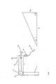
- FIG. 4 shows reference to FIG. 2 and represents the corresponding situation for a backlash measurement on the Achsgesch 2 in the left half of the picture. Therefore, for the comparable Components have also been the same reference numerals as used in Figure 1. Shown again is the first Roboterachsschenkel 4 in his, horizontal in this image, unloaded starting position and in the upper deflection position 28th
- the displacement sensor 18 is at a distance L from the axis of rotation 8.
- the first Roboterachsschenkel 4 is also by an angle ⁇ by the force of the Load device spent in the deflection position 28.
- a thereby covered Distance ⁇ S, seen along the measuring line of the displacement sensor 18, corresponds approximately the distance actually traveled by the first robot axis leg 4.
- This equation can be further improved by introducing correction factors.
- the displacement sensor 18 only the path difference ⁇ S must be measured in order to arrive at an angle indication, which alone of geometric Arrangement data is dependent.
- the first robot knuckle only is acted upon with such a force that just the gear play recognizable is, without the bending of the Roboterachsschenkels 4 due to the Force reaches a significant amount that could affect the measurement, then the measuring arrangement provides a very accurate calculation basis for the Calculation of the game.
- FIG. 5 shows the example of a connection possibility between a robot controller 60, which controls a robot 62, and a first system for wear estimation 64.
- An interface 66 between the robot controller 60 and the first system 64 is bordered by a dashed frame and includes a number of interface points, labeled X5, X6, X7 and X8.
- the interface 66 is included provided for the tapping of two robot axes, and it readily conceivable that a multiplicity of signals of different axes over the interface be queried or removed.
- the side of the interface 66 on which the robot 62 as well its controller 60 by displaying the icons for a robot 62 and its robot controller 60 are shown.
- the interface 66 connects the connection point X6 a first data line 68 with a first data selection switch 70 of the robot controller 60.
- the connection point is X5 with a second data line 72 with a second data selection switch 74 connected.
- the first data line 68 either with a signal of an absolute position of a first robot axis A1 or a torque signal of the first axis A1 are switched.
- the switching element 76 connects the data line 68 with the absolute position of the first axis A1.
- the second data line 72 is with the torque signal for a second axis A2 of the robot 62 connected.
- the selected example thus shows the wiring of the interface 66 with data from the Robot control 60, which concern only one file. It is without further thought that the data of several or all axes of the robot 62 to a corresponding interface be hung up.
- the advantage of this wiring is that compared to absolute position of the axis, the position in the current program, which the robot 62 has to process, represents a corresponding torque value respectively assigned can be.
- the interface 66 is also connected to the measuring computer 64 that is indicated by a first arrow 82.
- the measuring computer is by a fourth data line 84 with a server 86 and this with a fifth data line 88 connected to a PC 90.
- the measuring computer has the Task the values of the robot file provided analogously at the interface to interpret as values for a torque curve.
- the through the measuring computer 64 processed values for the torque curve are transmitted through the fourth data line 84, the surfer 86 and the fifth data line 88 to the PC 90 transmitted.
- the inventive method runs as follows. From the robot controller 60 at the connection point X6 on the first Data line 68 data signals provided as the absolute position of the first Act A1. In a similar way, the robot controller 60 via the second data line 72, a value for the torque just applied is applied to the first axis of the robot 62. Both values are combined detected by a time signal from the measuring computer 64 and stored first.
- the signal value for the absolute position of the first axis of the robot 62 is for the Method according to the invention is not absolutely necessary, but simplified for expedient embodiment of the method according to the invention the interpretation of Measured values for the torque.
- This also stores the received first Torque curve of the first axis from.
- the Working cycle of the robot 62 in the first step from starting and gripping a Workpiece exist.
- the second step is lifting the workpiece with then transferring it to an end position for the workpiece.
- the third step for the robot 62 is to release the workpiece and move the robotic arm back to its starting position so that the now finished cycle could be repeated.
- the working cycle defined by the working sections is initially called torque curve displayed on the display device of the PC 90.
- Each torque history section a predetermined torque band, ie permissible minimum torque and leave maximum values for the torque band of this axis analyzed as such and in a subsequent process step of evaluation subjected.
- a simple evaluation step only the frequency is calculated the leaving of the torque band within a certain time, given through the work cycle, used as a benchmark for the assessment.
- Another Possibility is that the curve in an analyzed torque history section used for the evaluation.
- the Frequency and / or the curve of the torque profile sections if necessary additionally provided with an empirically determined factor, the current axis wear estimated on the basis of such a work cycle.
- axle wear per work cycle The simplest with the A method according to the invention which can be estimated is axle wear per work cycle. With the knowledge of the working cycle of the Robot 62 according to the invention then also the current state of wear of the Robot 62 and the respective first axis are closed. by virtue of This estimate is then also allows a statement that is based on refers to the period of time with which this robot axis still in the current working cycle can be operated.
- FIG. 6 shows the example of a data flow from robot controller 60 of the robot 62 via a TCP / IP interface 92 through which the data from the robot controller 60 can be fed to a TCP / IP server with network 94.
- a TCP / IP network 94 thus connects an evaluation device 96 with the robot controller 60.
- the evaluation device 96 is location independent of the robot controller 60 may be connected by means of the network 94. In the example chosen this is on TCP / IP network.
- the interface 92 in other Networks for example, that the interface 92 an Internet interface is, so that the network 94 is formed by the Internet, and the evaluation device 96th thus can stand anywhere in the world without local restriction.
- the system according to the invention is for wear estimation of axes of a robotic arm of an industrial robot with all its modules in the Evaluation device 96 realized.
- the torque curve is accordingly determined by the Interface 92 via the network 94 in the form of the robot controller 60 available provided data to the evaluation device 96 passed.
- a processing module 100 is possible, the data provided by the data collector 98 as torques for a Torque comparison, for the maximum value detection and for the representation of the data as curves, to interpret.
- an assessment module 102 the curve, the curve or certain aspects of the curve are evaluated as Wear, so at the end of the process according to the invention a statement about it can be taken to what extent a particular axis of the robot 62 special, abnormal loads or exceeding certain allowable loads is exposed and such a special wear is expected.
- These dates with other data of production, maintenance or robot movement program, as indicated in this figure in the movement module 102 improve overall the quality of the statement concerning the wear estimation respectively the state of the individual files.
- FIG. 7 shows a table 110 that provides exemplary data for a six-axis robot which originate from a production program which has a cycle time of 60 Seconds and operates 1000 cycles per 24 hours.
- the first column 112 denotes while the respective robot axes 1 to 6, wherein the respective axes line by line the following values are assigned.
- Column 2 gives for each axis an absolute value for the detected revolutions of the respective axis, the within one cycle time of the production program.
- Columns are the rotation values as indexed values, ie percentages as proportional Use of the respective axes plotted, with the sum of all specified Percentages 100%.
- a fourth column 118 are the absolute time values the respective axis are noted within a day and finally are in a fifth Column 120 the absolute times of using an axle during a work week, So a week with five days with a number of hours specified.
- One possibility is to use the highly loaded axle, namely the axle 3 in the chosen example as the relevant axis, so that the calculation of the Maintenance interval based on the 27% rotation rate of the total number of revolutions or due to the absolute number of revolutions, namely 63.7 revolutions here for the axis three, takes place and in this way together with the historical Data that is the data that indicates how many cycles have already been done by the robot, compared to the recommended maximum rpm according to the manufacturer's instructions for a next following maintenance, the maintenance interval as such or the remaining period until a next maintenance time.
- FIG. 1 Based on the numerical example of Figure 1 is a graphical processing of the data according to Table 110.
- a second table 100 is shown in this figure, whose first table column 102 contains the same information as the first column 112. The same applies to the second table column 104 and the third table column 106, the contents of which correspond to those of the second column 114 and the third column 116.
- Above the second table 100 is the statement of this table in a cake-shaped Graphic 108 processed and provided with an index 110, the color marked segments with an axis name.
Applications Claiming Priority (2)
| Application Number | Priority Date | Filing Date | Title |
|---|---|---|---|
| DE102004028557A DE102004028557A1 (de) | 2004-06-15 | 2004-06-15 | Verfahren und System zur Zustandsbewertung von wenigstens einem Achsgelenk |
| DE102004028557 | 2004-06-15 |
Publications (2)
| Publication Number | Publication Date |
|---|---|
| EP1607193A2 true EP1607193A2 (fr) | 2005-12-21 |
| EP1607193A3 EP1607193A3 (fr) | 2009-08-05 |
Family
ID=35063201
Family Applications (1)
| Application Number | Title | Priority Date | Filing Date |
|---|---|---|---|
| EP05010720A Ceased EP1607193A3 (fr) | 2004-06-15 | 2005-05-18 | Méthode et dispositif pour évaluer l'état d'au moins une articulation de robot |
Country Status (3)
| Country | Link |
|---|---|
| US (1) | US7603200B2 (fr) |
| EP (1) | EP1607193A3 (fr) |
| DE (1) | DE102004028557A1 (fr) |
Cited By (3)
| Publication number | Priority date | Publication date | Assignee | Title |
|---|---|---|---|---|
| CN102686369A (zh) * | 2009-08-14 | 2012-09-19 | Abb股份有限公司 | 用于诊断具有活动件的装置的设施 |
| WO2012167819A1 (fr) * | 2011-06-07 | 2012-12-13 | Siemens Aktiengesellschaft | Procédé de détermination de la durée de vie restante d'un composant d'une machine et programme d'ordinateur pour mettre ledit procédé en oeuvre |
| KR20200008997A (ko) * | 2017-05-18 | 2020-01-29 | 포르슝스젠트룸 율리히 게엠베하 | 피루브산 카르복실라제 및 피루브산 카르복실라제 암호화 dna, 상기 dna를 함유한 플라스미드 및 그 생산을 위한 미생물, 그리고 자체의 생합성에서 전구체로서 옥살로아세테이트가 포함되는 것인 생성물의 제조 방법, 그리고 염색체 |
Families Citing this family (10)
| Publication number | Priority date | Publication date | Assignee | Title |
|---|---|---|---|---|
| DE102004028558A1 (de) * | 2004-06-15 | 2006-01-05 | Abb Patent Gmbh | Verfahren und Messanordnung zur Spielmessung an einem Achsgelenk |
| DE102004028559A1 (de) * | 2004-06-15 | 2006-01-05 | Abb Patent Gmbh | Verfahren und System zur Verschleißabschätzung von Achsen eines Roboterarmes |
| DE102004028557A1 (de) * | 2004-06-15 | 2006-02-16 | Abb Patent Gmbh | Verfahren und System zur Zustandsbewertung von wenigstens einem Achsgelenk |
| EP1932629B1 (fr) * | 2006-12-11 | 2019-04-24 | ABB Research Ltd. | Procédé et système de commande pour surveiller l'état d'un robot industriel |
| DE102011010505A1 (de) | 2011-02-07 | 2012-08-09 | Dürr Systems GmbH | Anpassung der Dynamik zumindest eines Roboters |
| US8914724B2 (en) * | 2011-04-06 | 2014-12-16 | Savant Systems, Llc | Method and apparatus for creating and modifying graphical schedules |
| JP5289608B2 (ja) * | 2011-12-13 | 2013-09-11 | ファナック株式会社 | ロボット減速機寿命推定シミュレーション装置 |
| SE537534C2 (sv) * | 2013-08-27 | 2015-06-02 | Cognibotics Ab | Metod och system för bestämning av åtminstone en egenskap hos en manipulator |
| JP6881886B2 (ja) * | 2015-07-14 | 2021-06-02 | キヤノン株式会社 | 制御方法、ロボット装置、および駆動装置 |
| DE102020103856B4 (de) | 2020-02-14 | 2022-06-15 | Franka Emika Gmbh | Verschleißprüfung beim automatischen Optimieren von Roboterprozessen |
Family Cites Families (19)
| Publication number | Priority date | Publication date | Assignee | Title |
|---|---|---|---|---|
| US4676002A (en) * | 1984-06-25 | 1987-06-30 | Slocum Alexander H | Mechanisms to determine position and orientation in space |
| US5353238A (en) * | 1991-09-12 | 1994-10-04 | Cloos International Inc. | Welding robot diagnostic system and method of use thereof |
| US5424960A (en) * | 1991-09-24 | 1995-06-13 | Nf. T&M. Systems. Inc. | Apparatus for measuring torque, inertia moment, output and backlash using stepping motor |
| DE4316817A1 (de) * | 1993-05-19 | 1994-11-24 | Dewitta Spezialmaschf | Verfahren zur Betriebs-Überwachung des dynamischen Belastungs- und/oder Verschleißzustandes eines Getriebes und Einrichtung zu seiner Durchführung |
| US5406502A (en) * | 1993-06-29 | 1995-04-11 | Elbit Ltd. | System and method for measuring the operation of a device |
| JP3357143B2 (ja) * | 1993-09-30 | 2002-12-16 | ファナック株式会社 | ロボットの負荷をモニタするロボット制御装置 |
| JP3331024B2 (ja) * | 1993-10-13 | 2002-10-07 | ファナック株式会社 | 工具寿命管理方式 |
| SE9304246L (sv) * | 1993-12-22 | 1995-06-23 | Asea Brown Boveri | Förfarande vid övervakning av multivariata processer |
| JPH0991025A (ja) * | 1995-09-26 | 1997-04-04 | Fanuc Ltd | 動作デューティを考慮したロボットの最短時間制御方法 |
| US5857166A (en) * | 1996-08-30 | 1999-01-05 | Kim; Nam H. | Tool monitoring apparatus |
| US20020019722A1 (en) * | 2000-07-19 | 2002-02-14 | Wim Hupkes | On-line calibration process |
| DE10120943B4 (de) * | 2001-04-20 | 2005-02-10 | Wittenstein Ag | Verfahren zur Bestimmung der Auslegung und zur Optimierung der Lebensdauer |
| US20060085091A9 (en) * | 2001-07-13 | 2006-04-20 | Martin Kiesel | Electronic fingerprints for machine control and production machines |
| US7010386B2 (en) * | 2002-03-22 | 2006-03-07 | Mcdonnell Ryan P | Tool wear monitoring system |
| US20040111237A1 (en) * | 2002-12-04 | 2004-06-10 | Abb Inc. | Method for estimating residual life of industrial equipment |
| JP4529456B2 (ja) * | 2003-11-28 | 2010-08-25 | 株式会社安川電機 | 産業用ロボットの腕機構 |
| DE102004028558A1 (de) * | 2004-06-15 | 2006-01-05 | Abb Patent Gmbh | Verfahren und Messanordnung zur Spielmessung an einem Achsgelenk |
| DE102004028557A1 (de) * | 2004-06-15 | 2006-02-16 | Abb Patent Gmbh | Verfahren und System zur Zustandsbewertung von wenigstens einem Achsgelenk |
| DE102004028559A1 (de) * | 2004-06-15 | 2006-01-05 | Abb Patent Gmbh | Verfahren und System zur Verschleißabschätzung von Achsen eines Roboterarmes |
-
2004
- 2004-06-15 DE DE102004028557A patent/DE102004028557A1/de not_active Withdrawn
-
2005
- 2005-05-18 EP EP05010720A patent/EP1607193A3/fr not_active Ceased
- 2005-06-15 US US11/153,041 patent/US7603200B2/en not_active Expired - Fee Related
Non-Patent Citations (1)
| Title |
|---|
| None |
Cited By (4)
| Publication number | Priority date | Publication date | Assignee | Title |
|---|---|---|---|---|
| CN102686369A (zh) * | 2009-08-14 | 2012-09-19 | Abb股份有限公司 | 用于诊断具有活动件的装置的设施 |
| CN102686369B (zh) * | 2009-08-14 | 2014-12-24 | Abb股份有限公司 | 用于诊断具有活动件的装置的设施 |
| WO2012167819A1 (fr) * | 2011-06-07 | 2012-12-13 | Siemens Aktiengesellschaft | Procédé de détermination de la durée de vie restante d'un composant d'une machine et programme d'ordinateur pour mettre ledit procédé en oeuvre |
| KR20200008997A (ko) * | 2017-05-18 | 2020-01-29 | 포르슝스젠트룸 율리히 게엠베하 | 피루브산 카르복실라제 및 피루브산 카르복실라제 암호화 dna, 상기 dna를 함유한 플라스미드 및 그 생산을 위한 미생물, 그리고 자체의 생합성에서 전구체로서 옥살로아세테이트가 포함되는 것인 생성물의 제조 방법, 그리고 염색체 |
Also Published As
| Publication number | Publication date |
|---|---|
| US20050278067A1 (en) | 2005-12-15 |
| DE102004028557A1 (de) | 2006-02-16 |
| EP1607193A3 (fr) | 2009-08-05 |
| US7603200B2 (en) | 2009-10-13 |
Similar Documents
| Publication | Publication Date | Title |
|---|---|---|
| EP1607193A2 (fr) | Méthode et dispositif pour évaluer l'état d'au moins une articulation de robot | |
| EP1607192B1 (fr) | Méthode et système pour estimer l'usure des articulations d'un bras de robot | |
| EP2628575B1 (fr) | Procédé destiné à déterminer un couple et robot industriel | |
| EP1607714B1 (fr) | Procédé et dispositif pour mesurer le jeu d'un joint pivotable | |
| EP1866123B1 (fr) | Dispositif hydraulique de serrage de boulons filetés et procédé pour serrer des grosses vis au moyen de ce dispositif hydraulique de serrage de boulons filetés | |
| DE2735594A1 (de) | Verfahren und vorrichtung zum anziehen von gewindebefestigungselementen mit einer vorbestimmten spannung | |
| DE2015967A1 (de) | Verfahren und Vorrichtung zur Herstellung von verschraubten Rohrverbindungen | |
| DE102014012868B4 (de) | Datenerlangungsvorrichtung zur Erlangung der Ursache des Anhaltens einer Antriebsachse und von darauf bezogenen Informationen | |
| DE102011122212A1 (de) | Akkubetriebenes Schraubsystem mit reduzierter funkübertragener Datenmenge | |
| DE19956265B4 (de) | Vorrichtung zur Überwachung des Betriebs von Hubwinden | |
| EP2388565B1 (fr) | Dispositif de mesure et robot | |
| EP1607894A1 (fr) | Méthode et système pour déterminer la nécessité d'entretien | |
| DE102018008370A1 (de) | Lebensdauervorhersagegerät | |
| DE102020126209A1 (de) | Roboter | |
| EP3698924A2 (fr) | Procédé de vissage ou de dévissage attesté d'un raccord à vis | |
| EP1757739A2 (fr) | Dispositif d'avertissement de surcharge pour une excavatrice | |
| WO2018068071A1 (fr) | Procédé permettant de déterminer une charge et commande pour un dispositif de levage hydraulique servant à mettre en œuvre un tel procédé | |
| DE102017108492A1 (de) | Steuervorrichtung eines Roboters, die ein Betriebsprogramm, in dem der Zustand einer zusätzlichen Achse enthalten ist, anzeigt | |
| EP3181260B1 (fr) | Identification d'un patinage | |
| EP0447511B2 (fr) | Procede et systeme pour surveiller une installation, telle qu'une grue automobile, un gros excavateur ou similaire | |
| DE102012010716A1 (de) | Ermitteln einer Qualität einerAluminiumschweißung | |
| DE10228389A1 (de) | Schwingungssensor und Verfahren zur Zustandsüberwachung von rotierenden Bauteilen und Lagern | |
| DE19828675C2 (de) | Verfahren und Vorrichtung zum Einstellen von mittels eines Verstellmechanismus translatorisch verstellbaren Richtrollen eines Richtapparates zum Richten von Draht | |
| WO2016037208A1 (fr) | Presse plieuse | |
| DE102018113880A1 (de) | Verfahren zum Betreiben einer Presse |
Legal Events
| Date | Code | Title | Description |
|---|---|---|---|
| PUAI | Public reference made under article 153(3) epc to a published international application that has entered the european phase |
Free format text: ORIGINAL CODE: 0009012 |
|
| AK | Designated contracting states |
Kind code of ref document: A2 Designated state(s): AT BE BG CH CY CZ DE DK EE ES FI FR GB GR HU IE IS IT LI LT LU MC NL PL PT RO SE SI SK TR |
|
| AX | Request for extension of the european patent |
Extension state: AL BA HR LV MK YU |
|
| 17P | Request for examination filed |
Effective date: 20070511 |
|
| PUAL | Search report despatched |
Free format text: ORIGINAL CODE: 0009013 |
|
| AK | Designated contracting states |
Kind code of ref document: A3 Designated state(s): AT BE BG CH CY CZ DE DK EE ES FI FR GB GR HU IE IS IT LI LT LU MC NL PL PT RO SE SI SK TR |
|
| AX | Request for extension of the european patent |
Extension state: AL BA HR LV MK YU |
|
| RAP1 | Party data changed (applicant data changed or rights of an application transferred) |
Owner name: ABB AG |
|
| 17Q | First examination report despatched |
Effective date: 20091125 |
|
| AKX | Designation fees paid |
Designated state(s): AT BE BG CH CY CZ DE DK EE ES FI FR GB GR HU IE IS IT LI LT LU MC NL PL PT RO SE SI SK TR |
|
| STAA | Information on the status of an ep patent application or granted ep patent |
Free format text: STATUS: THE APPLICATION HAS BEEN REFUSED |
|
| 18R | Application refused |
Effective date: 20100927 |