EP1607162B1 - Dispositif pour le soudage à l'arc pulsé et procédé d'utilisation - Google Patents
Dispositif pour le soudage à l'arc pulsé et procédé d'utilisation Download PDFInfo
- Publication number
- EP1607162B1 EP1607162B1 EP05004410A EP05004410A EP1607162B1 EP 1607162 B1 EP1607162 B1 EP 1607162B1 EP 05004410 A EP05004410 A EP 05004410A EP 05004410 A EP05004410 A EP 05004410A EP 1607162 B1 EP1607162 B1 EP 1607162B1
- Authority
- EP
- European Patent Office
- Prior art keywords
- pulse
- current
- circuit
- short circuit
- electric arc
- Prior art date
- Legal status (The legal status is an assumption and is not a legal conclusion. Google has not performed a legal analysis and makes no representation as to the accuracy of the status listed.)
- Active
Links
- 238000000034 method Methods 0.000 title claims abstract description 163
- 238000003466 welding Methods 0.000 claims abstract description 140
- 230000008569 process Effects 0.000 claims abstract description 113
- 238000010891 electric arc Methods 0.000 claims abstract description 58
- 229910052751 metal Inorganic materials 0.000 claims description 78
- 239000002184 metal Substances 0.000 claims description 78
- 230000007704 transition Effects 0.000 claims description 9
- NINIDFKCEFEMDL-UHFFFAOYSA-N Sulfur Chemical compound [S] NINIDFKCEFEMDL-UHFFFAOYSA-N 0.000 claims description 8
- 229910052717 sulfur Inorganic materials 0.000 claims description 8
- 239000011593 sulfur Substances 0.000 claims description 8
- 230000001105 regulatory effect Effects 0.000 claims description 6
- 230000003247 decreasing effect Effects 0.000 claims description 3
- 230000000670 limiting effect Effects 0.000 claims description 3
- 230000004913 activation Effects 0.000 claims 1
- 238000012546 transfer Methods 0.000 description 26
- 230000002829 reductive effect Effects 0.000 description 20
- 230000008901 benefit Effects 0.000 description 16
- 238000005516 engineering process Methods 0.000 description 14
- 230000004044 response Effects 0.000 description 13
- 238000010586 diagram Methods 0.000 description 12
- 239000007787 solid Substances 0.000 description 12
- 230000004048 modification Effects 0.000 description 11
- 238000012986 modification Methods 0.000 description 11
- 239000007789 gas Substances 0.000 description 9
- 230000004907 flux Effects 0.000 description 8
- 238000000926 separation method Methods 0.000 description 7
- XKRFYHLGVUSROY-UHFFFAOYSA-N Argon Chemical compound [Ar] XKRFYHLGVUSROY-UHFFFAOYSA-N 0.000 description 6
- 230000003044 adaptive effect Effects 0.000 description 6
- 239000011324 bead Substances 0.000 description 6
- 230000009467 reduction Effects 0.000 description 6
- 229910000831 Steel Inorganic materials 0.000 description 5
- 238000002844 melting Methods 0.000 description 5
- 230000008018 melting Effects 0.000 description 5
- 230000033764 rhythmic process Effects 0.000 description 5
- 239000010959 steel Substances 0.000 description 5
- 229910052782 aluminium Inorganic materials 0.000 description 4
- XAGFODPZIPBFFR-UHFFFAOYSA-N aluminium Chemical compound [Al] XAGFODPZIPBFFR-UHFFFAOYSA-N 0.000 description 4
- 230000000875 corresponding effect Effects 0.000 description 4
- 230000009471 action Effects 0.000 description 3
- 229910052786 argon Inorganic materials 0.000 description 3
- 150000001875 compounds Chemical class 0.000 description 3
- 238000001514 detection method Methods 0.000 description 3
- -1 ferrous metals Chemical class 0.000 description 3
- 239000007921 spray Substances 0.000 description 3
- 229910000990 Ni alloy Inorganic materials 0.000 description 2
- 230000009286 beneficial effect Effects 0.000 description 2
- 239000003795 chemical substances by application Substances 0.000 description 2
- 230000001276 controlling effect Effects 0.000 description 2
- 230000001627 detrimental effect Effects 0.000 description 2
- 239000000203 mixture Substances 0.000 description 2
- 230000035515 penetration Effects 0.000 description 2
- 230000001020 rhythmical effect Effects 0.000 description 2
- CWYNVVGOOAEACU-UHFFFAOYSA-N Fe2+ Chemical compound [Fe+2] CWYNVVGOOAEACU-UHFFFAOYSA-N 0.000 description 1
- 229910001069 Ti alloy Inorganic materials 0.000 description 1
- RTAQQCXQSZGOHL-UHFFFAOYSA-N Titanium Chemical compound [Ti] RTAQQCXQSZGOHL-UHFFFAOYSA-N 0.000 description 1
- 230000002411 adverse Effects 0.000 description 1
- 229910045601 alloy Inorganic materials 0.000 description 1
- 239000000956 alloy Substances 0.000 description 1
- 230000015572 biosynthetic process Effects 0.000 description 1
- 239000000356 contaminant Substances 0.000 description 1
- 238000011109 contamination Methods 0.000 description 1
- 230000002596 correlated effect Effects 0.000 description 1
- 230000001934 delay Effects 0.000 description 1
- 230000000881 depressing effect Effects 0.000 description 1
- 230000006872 improvement Effects 0.000 description 1
- 230000000977 initiatory effect Effects 0.000 description 1
- 230000007246 mechanism Effects 0.000 description 1
- 238000004021 metal welding Methods 0.000 description 1
- 238000005272 metallurgy Methods 0.000 description 1
- 229910001000 nickel titanium Inorganic materials 0.000 description 1
- 238000011017 operating method Methods 0.000 description 1
- 230000010355 oscillation Effects 0.000 description 1
- 230000036961 partial effect Effects 0.000 description 1
- 230000000737 periodic effect Effects 0.000 description 1
- 238000012545 processing Methods 0.000 description 1
- 230000001737 promoting effect Effects 0.000 description 1
- 238000011084 recovery Methods 0.000 description 1
- 230000003252 repetitive effect Effects 0.000 description 1
- 238000004904 shortening Methods 0.000 description 1
- 230000011664 signaling Effects 0.000 description 1
- 239000002893 slag Substances 0.000 description 1
- 239000010935 stainless steel Substances 0.000 description 1
- 229910001220 stainless steel Inorganic materials 0.000 description 1
- 239000010936 titanium Substances 0.000 description 1
Images


Classifications
-
- B—PERFORMING OPERATIONS; TRANSPORTING
- B23—MACHINE TOOLS; METAL-WORKING NOT OTHERWISE PROVIDED FOR
- B23K—SOLDERING OR UNSOLDERING; WELDING; CLADDING OR PLATING BY SOLDERING OR WELDING; CUTTING BY APPLYING HEAT LOCALLY, e.g. FLAME CUTTING; WORKING BY LASER BEAM
- B23K9/00—Arc welding or cutting
- B23K9/09—Arrangements or circuits for arc welding with pulsed current or voltage
-
- G—PHYSICS
- G07—CHECKING-DEVICES
- G07F—COIN-FREED OR LIKE APPARATUS
- G07F17/00—Coin-freed apparatus for hiring articles; Coin-freed facilities or services
- G07F17/0064—Coin-freed apparatus for hiring articles; Coin-freed facilities or services for processing of food articles
- G07F17/0071—Food articles which need to be processed for dispensing in a cold condition, e.g. ice and ice cream
-
- B—PERFORMING OPERATIONS; TRANSPORTING
- B23—MACHINE TOOLS; METAL-WORKING NOT OTHERWISE PROVIDED FOR
- B23K—SOLDERING OR UNSOLDERING; WELDING; CLADDING OR PLATING BY SOLDERING OR WELDING; CUTTING BY APPLYING HEAT LOCALLY, e.g. FLAME CUTTING; WORKING BY LASER BEAM
- B23K9/00—Arc welding or cutting
- B23K9/06—Arrangements or circuits for starting the arc, e.g. by generating ignition voltage, or for stabilising the arc
- B23K9/073—Stabilising the arc
- B23K9/0738—Stabilising of the arc by automatic re-ignition means
-
- G—PHYSICS
- G07—CHECKING-DEVICES
- G07F—COIN-FREED OR LIKE APPARATUS
- G07F11/00—Coin-freed apparatus for dispensing, or the like, discrete articles
- G07F11/46—Coin-freed apparatus for dispensing, or the like, discrete articles from movable storage containers or supports
- G07F11/58—Coin-freed apparatus for dispensing, or the like, discrete articles from movable storage containers or supports the articles being supported on or by endless belts or like conveyors
-
- G—PHYSICS
- G07—CHECKING-DEVICES
- G07F—COIN-FREED OR LIKE APPARATUS
- G07F9/00—Details other than those peculiar to special kinds or types of apparatus
- G07F9/10—Casings or parts thereof, e.g. with means for heating or cooling
- G07F9/105—Heating or cooling means, for temperature and humidity control, for the conditioning of articles and their storage
Definitions
- the present invention relates to a novel electric arc welder and more particularly to an electric arc welder according to the preamble of claim 1 for performing a novel pulse welding process, and to a method of pulse welding according to the preamble of claim 25 and using the novel arc welder.
- pulse welding which primarily uses a solid wire electrode with an outer shielding gas.
- MIG welding utilizes spaced pulses which first melt the end of an advancing wire and then propel the molten metal from the end of the wire through the arc to the workpiece. Under ideal conditions, a globular mass of molten metal is melted and transferred during each pulse of the pulse welding process.
- An interruption in the normal operation of a pulse welding process occurs when the molten metal contacts the workpiece before being released from the advancing wire. Consequently, the high voltage pulse welding of over 25 volts is normally used so that the gap between the end of the electrode and the wire is relatively large. This limits the incidence of short circuits and the resulting spatter and puddle disturbance.
- pulse welding usually requires a substantially higher voltage to assure proper transfer of the molten metal and to reduce short circuits. Nevertheless, the pulse welding process invariably involves a short circuit condition which must be eliminated rapidly to obtain the consistency associated with proper pulse welding.
- To remove short circuits it is well known to increase the arc current immediately upon detection of the short circuit. The high arc current causes an electrical necking action to immediately separate the molten metal from the advancing electrode to again establish the arc. A discussion of this well known concept is contained in Ihde 6,617,549. Even with this well known short circuit clearance procedure, high voltage is still required for solid wire and the travel rate of the wire must be fairly low.
- Short circuits in a pulse welding process affects arc stability, especially at lower voltages where the average arc length is less than about 0.20-0.30 inches (0.51-0.76 cm). They also cause spatter during breaking of the short circuit. Consequently, pulse welding requires a procedure for clearing of inadvertent, random short circuits. This was done by merely increasing the arc current until the short circuit was cleared. Thus, the pulse welding process required high voltages, greater than 25 volts, to minimize inadvertent short circuits. This resulted in the need to operate at lower travel speeds. Furthermore, spatter and non-uniform weld beads resulted when high voltages and normal short circuit clearing was employed.
- Pulse MIG welding primarily uses a solid wire electrode, metal cored wire, or flux cored wire typically shielded with an outer shielding gas.
- the power source creates a special pulsed output that alternates between a high output, sometimes called the "peak” and a lower output, called the “background.”
- the peak output is greater than the welding electrode's spray transition current for a duration long enough to form and transfer one droplet of metal from the advancing electrode to the workpiece.
- the lower background output allows the electrode to advance toward the workpiece and be repositioned in order for the next peak to deposit the next droplet.
- the pulsed output is maintained such that one droplet transfers from the electrode to the workpiece for each peak without allowing the droplet to bridge the gap causing a short circuit. This condition can be achieved when a sufficiently long arc length is maintained producing a relatively high average arc voltage. For example, pulse welding with a steel electrode running under 90% argon, 10% CO 2 is performed with an average voltage greater than about 26 volts.
- Cored wires are wires that are comprised of a metal sheath containing a core of metal power and/or slag producing compounds (FCAW-G) and/or compounds that produce shielding gases (FCAW-S). These wires are very advantageous to produce the desired metallurgy of the weld metal and to protect from contamination. Many of these cored wires can be used in a pulse welding process in a fashion similar to solid wires. However, in use of solid wires, these cored wires exhibit an increase in the frequency and severity of short circuits as the arc length is reduced.
- the minimum arc length required for cored wires is higher than the minimum arc length or voltage for a solid wire since pulsing cored wires tends to melt the sheath leaving the core exposed allowing it to dip into the puddle.
- the advantage associated with cored electrodes can not be fully employed.
- the present invention as defined in the claims relates to an electric arc welding and method of using the same which performs a pulse welding procedure where a short arc length (less than 0.10 inches (0.25 cm)) or a low voltage of 17-22 volts can be used to control the puddle and prevent arc from skipping ahead of the puddle. Furthermore, the travel speed is increased with the use of a lower arc length and, thus, lower voltage without promoting shorting as previously described.
- the use of the present invention ensures that shorting occurs at low background current. This avoids spatter associated with a high current when entering a short and high current when exiting a short.
- the present invention ensures reliable separation of the wire tip and the puddle surface, even with small arc lengths. This enhances rhythm and stability in the high current pulse and in the low background current cycle.
- the invention is designed for high speed automatic welding of the type performed by a robot where a low voltage, short arc length is obtainable so that the travel speed can be increased.
- the invention improves low voltage welding at high speeds as it stabilizes the shortened arc length and thus reduces spatter.
- a short circuit in the pulse welding process is detected and cleared in accordance with standard technology; however, after the short circuit is cleared, a plasma boost pulse is created.
- This boost pulse is a high current pulse with power in the range of 5-20 kW and preferably in the range of 10-20 kW of regulated power.
- the power of the plasma boost pulse is generally over 5 kW; however, when welding aluminum the plasma boost pulse can be reduced to 1.0-2.0 kW. Thus, the practical range is 1.0 kW to about 20 kW.
- This high current plasma boost pulse increases the output arc current at separation of the short circuit.
- This boost pulse increases the arc force to push the puddle away from the electrode, so that another short circuit does not occur during the same cycle.
- the plasma boost pulse heats the end of the electrode rounding the end of it to about the size of the wire diameter and an increase in arc force creates a separation between the wire and puddle so the electrode does not immediately short again.
- the weld process is continued.
- the low background current of the pulse welding process allows the droplet to be pushed closer to the puddle before the next pulse transfers the formed droplet into the puddle.
- the invention involves the provision of a current, voltage or power pulse after the short circuit condition has been cleared using a standard short circuit clearing procedure used in many welders. This stabilizes the weld puddle and immediately allows resumption of the normal pulse welding process so that a high voltage and low speed is not required for the process. Even though the electric arc welder and method are designed basically for automated applications with high travel speed and low voltage, the invention is also used for semi-automatic applications where penetration must be reduced and is advantageous for cored wires, where high travel speed is required. It has also been applied to pulse welding using flux cored wire.
- the plasma boost pulse is similar to the STT peak current pulse in that it creates a droplet on the end of the electrode and forces the puddle from the electrode.
- the STT welding process has been pioneered by The Lincoln Electric Company and is disclosed in several patents, such as Parks US-A-4,866,247 , referenced herein as background information.
- the STT process has a waveform intentionally creating a short circuit.
- the use of a plasma boost pulse immediately after the clearance of a short circuit does not constitute a generated portion of the waveform constituting the actual pulse welding process.
- a short circuit is a random event that is not detrimental when using the present invention to control the puddle when the short circuit is cleared so the next short circuit will be later in the process.
- the plasma boost is created during an interrupt in the normal pulse welding process to stabilize the puddle, reduce spatter and increase welding speed, while allowing low voltage operation for both solid metal electrodes and cored electrodes.
- short circuits caused by the drastically reduced voltage are not process disruptive.
- the welder is one using waveform technology pioneered by The Lincoln Electric Company of Cleveland, Ohio.
- the pulses and background current portions are formed by a high switching speed power source as small pulses created at a rate of over 18 kHz with a profile controlled by a waveform generator.
- the plasma boost pulse is preceded by a novel short circuit clearing process similar to the STT process.
- a short circuit is detected, the arc current is reduced and then allowed to increase along a pinch pulse profile with a first abrupt slope and then a more gradual slope.
- a premonition circuit normally a dv/dt detector is actuated when the short circuit is ready to "neck" or break. Then the arc current is dropped to a low level to reduce spatter. This terminates the short circuit and provides smooth surface tension transfer so the short circuit is really an excellent procedure for transferring metal to the workpiece.
- the plasma boost pulse of the invention is outputted by the welder. This is a practical procedure for clearing the short circuit in a pulse welding process and is novel when in combination with the other advances of the present invention.
- an electric arc welder for performing a pulse welding process by a voltage driven current between an advancing electrode and a workpiece.
- the current can be controlled by voltage or current regulation.
- the welder comprises a short detecting circuit creating a short signal upon occurrence of a short circuit between the advancing electrode and the workpiece and boost circuit to create a plasma boost pulse after the detection of a short circuit.
- there is a standard short circuit clearing circuit that increases the arc current after the short circuit signal and before the plasma boost pulse. This removes the short circuit before the plasma boost pulse.
- the plasma boost pulse has a regulated power in the general range of 1.0 kW to 20 kW and more particularly in the range of 10-15 kW.
- the plasma boost pulse has a duration in the general range of 0.2-5.0 ms.
- the invention is quite useful when welding with a cored wire electrode, such as metal cored and flux cored wire electrodes.
- the plasma boost pulse occurs during an interrupt in the normal waveform generator that creates the waveforms constituting a pulse welding process.
- the boost circuit for creating the plasma boost pulse of the pulse welding process also includes the creation of a controlled background current following the plasma boost pulse.
- This background current is normally different from the background current of the pulse waveform and continues until the next generated pulse in the pulse welding process.
- the end of the generated background segment resets the timer to initiate the standard pulse wave process.
- the background segment is adjustable in some instances by a voltage feedback from the output arc voltage of the welding process. The arc voltage created during a specific plasma boost pulse controls the background segment following that specific plasma boost pulse.
- a method of pulse welding by a series of pulses between an advancing electrode and a workpiece comprises detecting a short circuit between the electrode and the workpiece and then creating a plasma boost pulse after the short circuit.
- the plasma boost pulse occurs after the short circuit has been cleared in accordance with standard technology.
- a plasma boost pulse having a defined shape or profile (with a high current pulse and a background segment) is incorporated as part of the actual welding process so that a plasma boost pulse of a desired shape is created between the standard pulses of the pulse welding process.
- a plasma boost pulse preheats the end of the electrode and creates a droplet for the next pulse that transfers the droplet to the puddle.
- This can be used in a GMAW-pulse welding process using non-ferrous metals, such as nickel alloy or titanium alloys.
- Cored wires including metal cored wire, such as FCAW-G and FCAW-S wires can be used with this welding process.
- the present invention relates to an electric arc welding and method of using the same, which performs a pulse welding procedure where a short arc length (less than about 23 to 25 volts) is desirable to reduce the heat input and to improve fast follow characteristics at increased travel speeds.
- a short arc length (less than about 23 to 25 volts) is desirable to reduce the heat input and to improve fast follow characteristics at increased travel speeds.
- the use of the present invention in cooperation with conventional pulse MIG technology promotes arc stability when operating at short arc lengths and low voltages. It also ensures reliable, consistent separation of the welding electrode and puddle surface after a short circuit has been cleared. This procedure enhances rhythm and stability throughout a wide range of operating procedures.
- the invention was developed for high-speed automatic welding of the type performed by a robot where low voltage and, thus, a short arc length is desirable to improve welding performance at increased travel speeds.
- the invention is used for sem-automatic applications where reduced heat input is desirable. Pulse waveforms using this invention can be adjusted for longer arc lengths and will perform similarly to conventional pulse technologies. But, the real advantage is obtained by using low voltage where short circuits are more numerous.
- a plasma boost pulse can be described as pulsing the output to a defined amplitude of a defined duration.
- a plasma boost pulse can be defined as an output current voltage, power or volt/ampere slope level with the preferred implementation using a power level.
- This plasma boost is defined as a power level from 1.0 kW to 20 kW continuing for 0.2 to 5 ms. In practice, the plasma boost pulse is set for 10 to 15 kW with a duration of 0.2 to 0.5 ms.
- the concept of a plasma boost pulse is an energy based upon a power level maintained for a time.
- the manner of obtaining this pulse can be varied.
- This high current plasma serves to increase the arc force just after the separation of a short circuit.
- the increase in arc force created by the boost pulse pushes the puddle away from the electrode, so that another short circuit does not occur during the same cycle.
- the plasma boost pulse heats the end of the electrode to create a molten metal droplet that will become the next droplet to be transferred by the subsequent pulse of the pulse welding process. After the short has been cleared and the plasma boost has increased the arc force and heated the end of the electrode, the normal pulse weld process is continued.
- the remaining low background current of the pulse welding process allows the droplet to be pushed closer to the puddle before the next pulse transfers the formed droplet into the puddle.
- This invention involves the provision for a current, voltage or power plasma boost pulse after the short circuit condition has been cleared using a standard short circuit clearing procedure. This stabilizes the weld puddle and allows immediate resumption of the normal pulse welding process so that steady operation is possible even at low voltages.
- the invention is also used for semi-automatic applications where penetration must be reduced and is substantially advantageous for metal cored wires where high travel speed is required. It has also been applied to pulse welding using flux cored wires.
- metal cored wire it has been determined that an effective amount of sulfur in the core improves the operation of the invention especially when using metal cored wire.
- the sulfur is in the range of 0.010- 0.030 percent by weight of the wire, and preferably 0.012 to 0.023 percent by weight of the wire.
- An advantage of the invention is that parameters of the pulse welding process can be set such as to actually promote shorting events.
- the transition to peak is fast to quickly start the formation of a droplet.
- the pulse peak time is reduced so that the droplet does not detach fully from the electrode during the peak current.
- the transfer of arc current to background is fast to quickly reduce the arc force on the puddle to allow it to rise and advance toward the droplet.
- the output current is forced below the actual background level to further promote the droplet to bridge between the electrode and the workpiece.
- the frequency is kept high to keep the droplet size small.
- the process can be run at levels where every droplet is transferred through a short circuit, thereby significantly reducing the heat input of the welding process.
- the ability to transfer metal across a short circuit infers that the electrode, i.e. solid wire, metal cored wire, or flux cored wire, is stable in a short circuit transfer mode.
- the present invention can improve the welding performance at shorter arc lengths.
- Metal cored wires with a stable short arc performance such as Lincoln Electric's MS-6 ad MC-706 wire can benefit from the present invention. Utilizing the present invention, these wires have the improved ability to handle poor fit up conditions and faster travel speeds. These wires include an effective amount of sulfur to cause the wire to operate uniformly during short circuit transfer of metal.
- the invention is a refined pulse welding process designed specifically to allow faster speeds than standard pulse waveforms. It improves low voltage welding at high speeds, as it stabilizes the process with shortened arc length. With conventional waveforms, the arc length is kept longer to avoid spatter, thus limiting travel speed. In the invention, the arc length is kept short and tight and spatter is avoided with control of the short circuit cycle. Thus, the shorter arc is stabilized with rhythmic short circuit cycles. The treatment of the short circuit reduces stubbing and spatter.
- the primary object of the present invention is the provision of an electric arc welder, which welder utilizes a plasma boost pulse after a short circuit has been cleared and before the next adjacent pulse for melting and transferring molten metal to the weld puddle.
- Another object of the present invention is the provision of an electric arc welder, as defined above, which welder can be operated at high speed, with a short arc length and/or with metal cored of flux cored wires.
- the core When using metal cored electrodes, the core has an effective amount of sulfur to improve the shape of the weld bead at high travel speeds.
- Still a further object of the present invention is the provision of an electric arc welder, as defined above, which welder is primarily useful for automatic welding in a robot and other mechanized welding mechanisms by a high travel speed, low voltage and low spatter.
- Yet another object of the present invention is the provision of a method of pulse welding wherein an inadvertent short is cleared and then followed by a plasma boost pulse having a high power, such as about 1-5 kW to 20 kW for a short time such as about 0.1-5.0 ms, preferably less than 1.0 ms.
- Yet a further object of the invention is the provision of an electric arc welder and method which can operate at low voltage and converts the short circuits of such a process to an advantageous metal transfer technique.
- Still a further object of the invention is the provision of an electric arc welder for pulse welding and a method for operating said welder, which welder and method provide faster travel speed, shorter cycle time, higher yield per time and increased productivity for automatic pulse welding, especially with a robot.
- Yet a further object of the invention is provision of a welder and method, as defined above, which welder and method performs fast welding on steel, such as plates in the range of 1.5 to 4.0 mm in thickness, without the risk of weld skips, undercuts or high spatter levels.
- the welder and method provide excellent arc stability at lower arc voltage (shorter arc length) with reduced spatter and washed out bead profile to thereby increase travel speed.
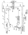
- FIGURES 1-3 illustrate a prior art electric arc welder A for performing a pulse welding process, as shown in FIGURE 2 .
- the prior art is illustrated since the components used in practicing the invention are essentially the same as standard components in electric arc welder.
- the preferred architecture is a welder controlled by waveform technology as pioneered by The Lincoln Electric Company of Cleveland, Ohio. Two of many patents relating to waveform technology is described in Blankenship US-A-5,278,390 and Fulmer US-B1-6,498,321 , referenced herein as background information.
- a waveform generator produces the profile for the waveforms used in a pulse welding process.
- the power source creates the pulses in accordance with the shape determined from the waveform generator by using a plurality of current pulses and at high frequency such as over 18 kHZ.
- This type of technology produces precise pulse shapes for any desired welding process. Even though the invention will be described with respect to the use of a welder employing waveform technology, the invention is broader and may be used in other welders, such as SCR controlled welders and chopper based welders.
- Electric arc welder A shown in FIGURE 1 is used to perform a standard pulse welding process as illustrated by the curves in FIGURE 2 with a plurality of operating signals indicated at various locations in FIGURE 1 and by corresponding numbers in FIGURE 3 .
- Electric arc welder A has a power source 10 in the form of a high speed switching inverter with output leads 12, 14 for creating the pulse welding process between electrode E and workpiece W.
- Power source 10 is driven by an appropriate power supply 16, illustrated as a three phase input.
- the profile of the pulses and separating background current constituting the pulse welding process is determined by a signal on wave shape input 18, in accordance with standard technology.
- Current shunt 22 communicates the arc current of the welding process by lines 24 to a current sensor 26 having an analog output 28 used for a feedback control loop.
- leads 30, 32 communicate the arc voltage to voltage sensor 34 having a detect output 36 and a level or amplitude output 38.
- the detect output indicates when the level of voltage plunges during a short circuit between electrode E and workpiece W.
- Level output 38 has a signal representative of the arc voltage across the electrode and workpiece.
- Voltage detect output 36 is directed to a shorting response circuit 40 having an output 42 which outputs a signal 3, as shown in FIGURE 3 . When there is a short circuit, there is a detect signal in line 42 in accordance with standard technology.
- Waveform generator 50 is loaded with the particular waveform to perform the welding process.
- Timer 52 directs a timing signal by lines 54 to waveform generator for the purpose of initiating the individual pulses constituting the welding process.
- Generator 50 also has feedback signals from lines 28, 38 to control the voltage and current in accordance with the set profile of the waveform generator and the existing profile between the electrode and workpiece.
- the waveform that is to be outputted by power source 10 is signal 2 in line 56.
- This signal is connected to the input of summing junction or adder 60 having an output 62 for signal 4.
- This signal in the prior art welder A, is the actual signal directed to input 18 of power source 10.
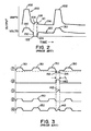
- FIGURE 2 The welding process performed by welder A is illustrated in FIGURE 2 wherein current curve 100 has a series of spaced current pulses 102 separated by background current portion 104.
- Voltage curve 120 is the voltage between lines 30, 32 and constitutes the arc voltage correlated with the arc current of curve 100. The peak voltage is a result of applying peak current 102.
- a low average voltage of curve 120 is due to a high instantaneous arc voltage average with a shorting or below about 6.0 volts.
- arc voltage 120 plunges as indicated by point 122. This voltage plunge indicates a short circuit of molten metal between the electrode and workpiece. When that occurs, a clearing procedure overrides the waveform shape in line 56.
- Signal 7 is the sensed voltage in line 36.
- voltage 120 includes a plurality of spaced pulses 130 having shapes determined by waveform generator 50 and spacing determined by timer 52. When there is a short at point 122, the voltage plunges along line 132. This causes a pulse 140 that generates an output in line 42 which output is in the form of signal 142 generally matching ramp 106 for the current curve 100 that is added to signal 2.
- the output of waveform generator 50 is signal 2 constituting the waveform signal 150 shown in FIGURE 3 .
- the output of summing junction 60 in line 62 is the summation of signals 2 and 3 which is shown as signal 4 in line 62.
- Ramp 142 is added to waveform 150 so that the output between electrode E and workpiece W is the signal in line 18 controlling the inverter type power source 10.
- the pulse welding process can be shifted from a high voltage process with an arc voltage, in a range greater than 26-27 volts, to a low voltage process where the arc voltage is less than 25 volts and specifically in the general range of 17-22 volts.
- the arc is stable with a very short arc length below about 0.20-0.30 inches (0.51-0.76 cm).
- the arc length is about 0.15 inches (0.38 cm) steel wire with 90% argon and 10% CO 2 . This allows a faster travel rate while still maintaining a good bead profile.
- Other wires can be used, such as aluminum or stainless steel.
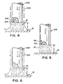
- FIGURES 4-5 Three different electrodes used in the invention are illustrated in FIGURES 4-5 .
- cored electrode 200 is advanced in the direction of the arrow and includes an outer steel sheath 202 and an inner core 204 formed from alloy agents and other compounds necessary for providing the desired weld metal in the weld bead.
- shielding gas 206 is directed around the arc to protect the arc from atmospheric contaminants.
- the arc length x is a length less than 0.30 inches (0.76 cm) and is created by voltage in the general range of 17-22 volts. This type of electrode is well suited for use in the present invention.
- FIGURE 5 Another cored electrode is shown in FIGURE 5 , where electrode 210 has an outer sheath 212 and an inner core 214.
- This electrode is a self-shielding electrode where the composition of core 214 provides fluxing agents and other compositions to protect the molten metal as it is transferred through the arc and onto the workpiece W.
- this cored electrode is useful in practicing the invention wherein cored electrodes in the past have not been successfully employed for pulse welding.
- FIGURE 6 shows solid wire electrode 220 with shielding gas 222. This is the normal wire heretofore used in pulse welding.
- This type electrode is the electrode normally used in MIG welding and particularly in pulse welding. By using the present invention, electrodes 200, 210 and 220 can now be used in pulse welding.
- the invention takes advantage of metallurgical and physical attributes of cored electrodes in pulse welding.
- the advantages of a cored electrode for STT welding is discussed in Stava US-A-6,071,810 referenced herein as background information.
- Cored electrodes can be used because the invention provides low voltage so the voltage range for the welding process by cored electrodes is extended.
- the low voltage of the invention allows the wire to travel faster.
- all of the electrodes shown in FIGURES 4-6 can be used according to the demands of the welding process. In the past high arc voltages prevented effective uses of all types of electrodes.
- the present invention allows very low arc voltage, the arc length is small and the molten metal often transfers to the workpiece by a short circuit.
- This process makes use of cored electrodes, especially metal cored electrodes, very acceptable for pulse welding. Indeed, a metal cored electrode with about 0.010 to 0.030 sulfur in the core have been proven extremely effective when obtaining the general advantage of the plasma boost pulse concept of the present invention.
- Wire electrodes, Metal Shield MC6 and MC 706 sold by The Lincoln Electric Company of Cleveland, Ohio have proven to be advantageous for use with a method using a plasma boost pulse where the shielding gas 75-95% argon with the balance CO 2 gas. These wires conform to the E70C-6M designation.
- Other metal cored electrodes and self shielding cored electrodes have taken advantage of the low voltage, low arc length obtainable in a process performed in accordance with the present invention.
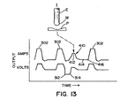
- FIGURES 7-9 The preferred embodiment of the invention is illustrated in FIGURES 7-9 that produces the pulse welding method best shown in FIGURE 7 .
- Current curve 300 includes spaced pulses 302 separated by background portions 304 determined by the output of waveform generator 50 with the pulses spaced by the output of timer 52. Of course, timing can be built into the program of the waveform generator. Background current 304 is provided between pulses 302 for use in keeping the arc lit after molten metal M has been formed and deposited onto the workpiece in the molten metal weld puddle.
- Voltage curve 310 includes a short circuit detect point 312 and a short circuit clear point 314.
- Curve 300 shows the normal high current clearing routine to generate portions 306, 308 corresponding to portions 106 and 108, respectively, of the prior art shown in FIGURE 2 .
- the invention involves the provision of a plasma boost pulse 320 preferably after the short circuit clear point 314 so the boost pulse occurs during an arc condition or a plasma condition. In practice, this plasma pulse is created during an interrupt of the output from waveform generator 50 and is substituted for the output of the generator at input 18 of power source 10.
- Plasma boost pulse 320 is a regulated power in the general range of 5-20 KW and preferably less than about 10-15 KW. For aluminum, the power may be as low as 1.0 KW.
- This pulse has a peak portion 322 that has a time distance y which is generally less than 5.0 ms and preferably in the range of .2-5.0 ms. In the present implementation, the time is 0.3 ms.
- Pulse 320 is terminated at the end of the peak portion 322 to enter a current reduction section where the arc current falls to background current level 304. In the preferred embodiment, this reduction in current is a long trailing edge 324 and a generally gradual tail out portion 326 so the plasma boost pulse is terminated before 5.0 ms.
- the operation of the plasma boost is depicted in the pictorial representations I-VI at the top of FIGURE 7 . Electrode E advances toward workpiece W while molten metal M is forming as shown at position I.
- the current between the electrode and workpiece is then increased to peak of pulse 302 causing the end of electrode E to melt further and produce a molten metal ball M.
- the operation of peak 302 is at position II.
- Workpiece W involves a molten metal puddle P which is cavitated by the arc force between electrode E and workpiece W.
- the molten metal M at the end of electrode E is transferred through the arc to the puddle P during the background portion 304 of the process. Then the process is repeated as shown in position VI.
- a short circuit between electrode E and puddle P by molten metal M is not formed as a part of a normal pulse welding operation.
- the arc voltage is plunged at point 312.
- the short circuit then initiates a high current clearing routine or sequence represented by portions 306, 308 to neck off and separate molten metal M from electrode E as shown in position IV. Then the present invention is implemented.
- a plasma boost pulse is outputted.
- the plasma boost pulse force puddle M away from electrode E as shown at position V.
- This high arc force cavitates puddle P drastically to assure a separation between molten metal M and molten puddle P. This assures that there is no incipient short or short circuit until after the next pulse 302.
- the low background current portion 304 is implemented by waveform generator 50.
- Position V represents a primary advantage obtained by using a plasma boost pulse following a short circuit in a pulse welding operation.
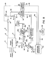
- welder B is provided with a plasma boost profile circuit 350 having a start interrupt signal in line 352 with the short circuit is cleared at point 314 in FIGURE 7 .
- a signal in line 352 when the point 314 is reached is communicated to timer 360 by line 362. This starts timer to create an interrupt time.
- This interrupt signal in line 362 continues until timer proceeds to its set time.
- the signal in line 362 from timer 360 sets the duration of the interrupt during which the plasma boost profile circuit 350 is operated.
- Output 354 processes the boost pulse profile during the interrupt when the interrupt signal in line 364 shifts switch 370 from the normal contact 372 and the interrupt contact 374.
- plasma boost circuit 350 outputs a profile signal in line 354 so long as timer 360 is timing to give a signal in line 364.
- This profile is the plasma boost pulse 320 shown in FIGURE 7 .
- switch 370 is a digital software switch to shift from the output 62 of summing junction 60 to the interrupt position while circuit 350 processes a profile indicated as signal 5. This signal is directed to input 18 of power source 10.
- the various signals are shown in FIGURE 9 with the numbers corresponding to the signals in FIGURE 3 .
- the new signals 5, 6, 10 and 11 are shown in the lower portion of FIGURE 9 and are coordinated in time with the other signals previously described.
- shorting response circuit 40 creates signal 10 in line 352, which signal is a pulse 380. This pulse starts the timing signal 11 which is a ramp signal 382 having a time out position 384.
- an interrupt signal 390 is maintained while the plasma boost profile in line 354 is processed by power source 10.
- the control voltage on input line 18 is in the form of pulse 392 shown as signal 6.
- a plasma boost is provided after the normal short circuit clearing routine has been performed by shorting response circuit 40 in accordance with standard practice.
- the plasma boost pulse can replace the short clearing routine; however, this is not a preferred implementation of the present invention.
- the standard pulse program from waveform generator 60 can be modified to improve the shorting events and improve the response to the short circuits so the events are not disruptive. These modifications include a fast transition from the low background current to the high peak current at the leading edge of pulse 302. This quickly increases the output to a level above the transition current to start melting of a droplet on the end of the electrode.
- the shorting response is a multi-ramp response that minimizes the initial response to the short circuit for separating incipient shorts and then increases the current response for clearing harder shorting events. This method has been used for many years in the Power Wave 455 manufactured by The Lincoln Electric Company when processing standard CV programs.
- FIGURES 10-12 An addition can be made to the preferred embodiment of the present invention as illustrated in FIGURES 10-12 wherein the plasma boost pulse or routine is modified to promote consistent detachment of the molten metal.
- the plasma boost creates a molten droplet on the end of the electrode that will be transferred during the next pulse cycle.
- the standard pulse waveforms are resumed.
- a short circuit will not occur at the same time for each of the pulses in the pulse welding process.
- the time required to clear a short is inconsistent from one short to the next. Consequently, the time the short clears in relationship to the next pulse determined by timer 52 will not be consistent.
- the remaining time after the plasma boost pulse is completed will be different when utilizing the preferred embodiment of the present invention.
- the background current 304 has sufficient time in the waveform created by waveform generator 50 to allow the electrode to travel closer to the puddle before the molten metal is transferred. This time is inconsistent from one short to the next for the reasons stated. Consequently, the position at the end of the electrode with respect to the puddle will not be consistent.
- a method for improving this consistency allows the end of the electrode to travel a consistent distance before the next pulse.
- This improvement in the basic method of the invention uses a dedicated background time and amplitude routine after the plasma boost itself has been processed.
- the waveform creating the plasma boost pulse is modified to include its own background current portion after the pulse. Consequently, timer 360 is used to control the duration of the plasma boost pulse and the background current time and magnitude.
- the plasma boost pulse serves to build a consistent droplet on the end of the electrode at a consistent distance from the puddle as shown in the top pictorial representations of FIGURE 10 .
- a consistent time and amplitude for the background segment or portion is used in the modification of the preferred embodiment. This modification is shown in FIGURES 10-12 .
- the plasma boost pulse is expanded to include a dedicated background amplitude and time.
- Timer 360 is used to set the time starting with the short circuit clearance signal appearing on line 352.
- electric arc welder C shown in FIGURE 11 is modified to reset timer 52 at the end of the interrupt during which line 354 controls input 18.
- the reset signal is a signal on line 400.
- plasma boost circuit 350 creates a signal 5 to generate a waveform 410 having a plasma boost pulse portion 412 and a background current portion 414 terminating at time 416. This is the time out of timer 360 to create a reset signal in line 400.
- timer 360 starts its timing sequence, there is an interrupt shown as pulse 420 in FIGURE 12 . This is the same interrupt as previously described.
- Timer 52 times along line 422 as shown in FIGURE 12 . At position 424, timer 52 resets causing a signal at time 426 in line 54 to start the next pulse 150 in signal 2 of generator 50.
- welder C creates a reset signal in line 400 when timer 360 reaches its set time at the end of the tailout section 414 at the plasma boost waveform 410.
- This reset signal is at time 430 shown in FIGURE 12 .
- Reset signal 1 terminates pulse 150 of signal 2 at the end of the plasma boost portion of waveform 410 to create a partial pulse 150a shown in FIGURE 12 .
- a waveform 410 is created by circuit 350 on line 354. This waveform during the interrupt has a precise profile for the plasma boost pulse 412 and the background current portion or segment 414.
- the next pulse 150b is caused to proceed. Consequently, when there is a short circuit there is a precise pulse and tail out or background current amplitude and time. This is shown in FIGURE 10 .
- the signal on line 18 by the interrupt position of switch 370 is a waveform 410 with pulse portion 412 and background current portion 414.
- a signal in line 400 occurs at time 416. This is when the predetermined waveform of the interrupt has been completed. Consequently, elements 412, 414 and 416 are consistent with each short.
- a new pulse 302 is initiated by timer 52.
- a signal 6 shown in FIGURE 12 is applied to input 18 for controlling the profile of the current or power between electrode E and workpiece W.
- the new profile is profile 440 in FIGURE 12 . Consequently, the output of waveform generator 50 is interrupted at the end of the short and a given pulse and background current segment is processed. The result of this waveform is shown in positions I-III in FIGURE 10 .
- the arc force pushes puddle P so it moves away from the end of electrode E. This is shown at position I.
- the background current portion allows puddle P to reform in a uniform manner. This is shown at position II.
- the molten metal M is ready to be transferred to workpiece W as shown at position III. This creates a consistent operation after each short circuit.
- the plasma boost signal includes a dedicated background portion 304 with a selected amplitude and duration, which is at a different level than level 414 in FIGURE 10 .
- the interrupt signal is maintained through waveform 410 including plasma boost pulse 412 and dedicated background portion or segment 414.
- Timer 52 is reset at the end of a dedicated background time. During the dedicated background portion, the waveform generator is ignored because the interrupt has switched control of input 18 to the output of plasma boost control circuit 350. The waveform generator is reset by timer 52.
- FIGURES 13-15 A slight modification of the embodiment illustrated in FIGURES 10-12 is disclosed in FIGURES 13-15 .
- Molten metal M formed on the end of the electrode after the plasma boost pulse will vary according to certain conditions during the plasma boost pulse. Consequently, a feedback loop sensing the arc voltage during the plasma boost pulse can be used to adjust the dedicated background segment 414.
- the arc voltage during the plasma boost pulse indicates the arc length during the pulse. This arc length is used to calculate background current portion amplitude and/or duration. Since the plasma boost is defined as a function of power, the voltage feedback is used to calculate the relative arc length and modify the background amplitude and/or duration. Adapting the background amplitude and duration will promote even more consistency of the electrode placement with regard to the puddle after a short circuit.
- An independent adaptive control is used in welder D shown in FIGURE 14 .
- This adaptive loop modifies background portion 414 in accordance with the sensed arc voltage occurring during the pulse portion 412 of waveform 410.
- the gain of this second adaptive control loop must be set so that the short plasma boost will directly affect the next background current segment. Consequently, only the background current amplitude and duration for the interrupt being processed is adapted.
- electric arc welder D allows the plasma boost to be controlled by an arc voltage feedback loop.
- adjustment of the amplitude and duration of the background portion 414 is accomplished by circuit 500 having an input 502 representing the arc voltage from voltage sensor 34.
- Output 504 is communicated with the plasma boost circuit to adjust the background portion during the interrupt determined by the time switch 370 is in the interrupt position 374.
- the background portion 414 (normally current) is a fixed profile, as previously described.
- Voltage from line 502 in FIGURE 14 adjusts portion 414 into the dashed line configuration of FIGURE 15 where the new background portion 414a of waveform 410 terminates at a new point 416a.
- Portion 414a is adjusted by the arc voltage during pulse portion 412, which voltage essentially corresponds to the arc length during the plasma boost pulse portion of waveform 410.
- electric arc welder D shown in FIGURE 14 is the same as welders A, B and C, as previously described.
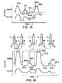
- Plasma boost pulse 600 with a boost pulse portion 602 and background portion 604 is inserted between each pulse 302 of curves 100, 120 as shown in FIGURE 16 .
- the plasma boost pulse preheats the end of the electrode and creates a droplet for the next pulse 302 for transfer to the molten metal puddle P.
- the first segment of the plasma boost pulse is a pulse that will preheat the end of the electrode and create a droplet. This preheat has been advantageously used in GMAW-pulse welding using non-ferrous metals, such as nickel alloys and titanium.
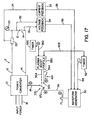
- the interrupt is started at time 612 when timer 360 starts.
- the output on line 354 is a waveform with profile 600a shown in FIGURE 18 .
- Timer 52 starts the next pulse 150 at time 424 and terminates interrupt 620 at this time.
- waveform 600a is directed through line 354 to input 18.
- signal 6 alternates between signal 2 from waveform generator 50 and fixed pulse profile shape 600b corresponding to waveform 410 in line 354.
- the interrupt is being processed to drive power source by input 18 from circuit 350.
- a plasma boost pulse 600 is routinely implemented between the normal pulse 302 by power source 10.
- the pulse portion of waveform 600a will heat the end of the electrode and create a molten droplet that is transferred during the next pulse.
- This method can be used alone or in combination with the timing sequence shown in FIGURE 18 .
- Other arrangements can be used to insert a plasma boost pulse between the standard current pulses 302 from waveform generator 50.
- Welder F could have the background adjustment feature of welder D as shown in FIGURE 14 as an option.
- the tailout for waveform 600a is fixed. Adaptive feedback from the voltage or arc length is optional.
- FIGURE 23 is a current curve of the practical implementation of the novel process where a plasma boost pulse is created between each pulse of a standard pulse welding process.
- a short circuit at point 910 occurs after each pulse 900.
- This short circuit is not at the peak of pulse 900, but is after decay portion 902.
- the short is cleared naturally by the rhythmic movement of the puddle to create a current hump 904.
- This second signal at point 912 is the trailing edge of pulse 140 in signal 9 as shown in FIGURE 9 .
- the short is cleared and plasma boost pulse 930 is created. Because of inherent time delays in the circuitry, there is a slight time delay 920 between the second signal at point 912 and start of pulse 930. Thereafter, background current 932 continues to the next pulse. The slight delay before clearing current would be before creation of pulse 142 in FIGURE 9 , but during the short the delay may be greater than the time to clear the short naturally. If the short is cleared before the delay has expired, then the welder goes directly into the plasma boost with its inherent delay 920. During pulse 900, there is a sudden increase in current to increase the arc energy to form and squeeze a molten droplet extending from the end of the electrode.
- the pulse is ramped down to relax the plasma force depressing the molten puddle. This allows the puddle to rise toward the droplet.
- a gentle plasma boost pulse pushes the puddle away and conditions the electrode tip. This assures reliable separation of the metal from the tip and the puddle resulting in a stable rhythm of the cycles.
- the delay before the clearing current allows the short to clear by the rhythm and not by a clearing current. If it does not clear during the delay, then the standard current clearing routine is implemented.
- the second signal at point 912 informs the controller that the short has been cleared whether naturally or by a clearing current. Then the plasma boost pulse is outputted. This is the practical operation of the welder in FIGURES 16-18 .
- FIGURES 19-21 The use of a waveform including a plasma boost pulse portion with a different short circuit clearing routine is another aspect of the present invention and is shown in FIGURES 19-21 .
- Welder G is similar to welder C disclosed in FIGURE 11 with the addition of a standard premonition circuit 700 with an input 702 and an output 704.
- a logic on the output indicates when the dv/dt of the arc voltage from sensor 34 exceeds a given level indicating an impeding short circuit during the clearance routine for a short circuit.
- the dv/dt circuit is standard and detects a slope equal to or greater than a reference value signaling the short is about to break.
- This circuit stops the shorting response circuit 40 so that the signal in line 325 terminates the arc portion 712 of waveform 710 shown in FIGURE 21 and initiates the plasma portion 714 on output 354 of plasma boost profile circuit 350.
- the output 704 of premonition circuit 700 is shown as pulse 720 in signal 12, one of the many number signals of welder G shown in FIGURE 20 .
- the various numbered signals in FIGURE 20 correspond to the numbers used in FIGURE 19 .
- Welder G generates the signals shown in FIGURE 20 , which signals are essentially the same as the like numbered signals illustrated in FIGURE 11 for welder C.
- the basic difference between welder G and welder C relates to short clearing portion 712 of waveform 710.
- waveform portion 712 of waveform 710 is implemented by the shorting response circuit 40.
- This portion of the waveform is different and includes a immediate reduction in current at the time of the short represented by portion 730.
- Circuit 40 holds the current low for a preset time 732, after which a clearance routine for the short circuit is implemented.
- This routine starts with a rapid increase in current along slope portion 734 followed by a second slope portion 736 which is somewhat more gradual.
- this current increase is directed through the short circuit, the short circuit begins to neck causing an increase in the dv/dt.
- this derivative reaches a specific level pulse 720 is created. This pulse immediately plunges the current to a low level similar to the level at reduction point 730.
- the premonition relation can be dv/dt, di/dt, dp/dt or other derivatives of time.
- Reduction of current caused by pulse 720 also starts waveform portion 714 of general waveform 710 illustrated in FIGURE 21 .
- waveform 710 is started by a break in the short circuit.
- Waveform portion 714 includes the plasma boost pulse 740 having a tailout portion 742. This tailout portion is more distinct in FIGURE 19 , but has a variety of configurations.
- Welder G utilizes a unique short circuit clearing procedure whereby the termination of the clearing routine is determined by the impending rupture of the short circuit, as opposed to a voltage detector employed in welder C. Otherwise, the clearing procedure is generally the same. The exception is the reduced current portion for time 732.
- Metal transfer line or current 744 is less than the peak current, but greater than the maximum current of the plasma boost pulse.
- the short circuit is cleared and a plasma boost pulse is initiated to force the molten metal puddle from the advancing electrode while the advancing electrode is forming a molten metal ball for the next transfer.
- waveform 710 shown in FIGURE 21 transfer of metal by short circuit is not disruptive and may even be advantageous. Indeed, it has been found when using the invention that transfer by a short circuit process after each pulse 150 of the pulse welding process has some advantages. Consequently, a modification of the invention has been developed which relies upon transfer of metal by short circuit in a pulse welding process. This modification uses the novel plasma boost pulse of the invention and is described in
- FIGURE 22 The use of the novel plasma boost pulse in a pulse welding process for the purpose of actually transferring metal by short circuit transfer, instead of the normal spray transfer is illustrated in FIGURE 22 .
- This aspect of the invention uses the elements from various electric arc welders so far described in detail.
- a normal pulse welding waveform is illustrated as curve 800 having pulses 802 separated by background current portions 804 and spaced to produce a period n.
- Each peak current stage 806 has a length or process time to melt the advancing electrode for the purposes of spray transfer as is normal. This transfer through the arc occurs at the end of the peak current stage and shown as point 810.
- Pulse 802 is intended to have enough energy to melt and propel a droplet of molten metal toward the workpiece.
- Peak current 806 has a value of 550 amperes and a length of time of about 2.0 ms.
- Background current 804 has a level of 90 amperes while period n is about 8.3 ms.
- These parameters are representative of a pulse welding process to which the invention has been added, as previously described.
- the present invention is used in a process that utilizes a short circuit condition to transfer the molten metal. This process can be employed due to the quiet puddle dynamics resulting from use of the present invention.
- the new pulse weld process of FIGURE 22 is illustrated by curve 820 where current pulses 830 are provided at a frequency which is increased as much as twice the frequency used in curve 800.
- period m between pulses 830 when compared to a normal pulse welding process, can be reduced to about 4.3 ms.
- the template for the process depicted as curve 820 also has other modifications from the normal pulse welding curve 800. For instance, the peak current is reduced to a level, such as 475 amperes, and has a shortened time of 1.5 ms.
- the reduction of current after the peak stage 832 is below background current level 834 to a lower current point 840.
- the puddle thus, rises toward the ball as the ball is moving toward the molten metal puddle.
- This short circuit is detected as previously described.
- the present invention then creates waveform 850. This waveform includes a pulse portion 852 and a tailout portion 854.
- This waveform occurs during the plasma portion when there is an arc to initiate melting of the advancing wire preparatory to the next pulse 830.
- a clearing circuit is activated at point 842 to provide a clearance routine having two slope portions 862, 864.
- curve 820 provides pulses at a higher frequency and with less energy in the pulses.
- a circuit activated at the end of a pulse plunges the arc current to assure a short circuit. Thus, a short circuit metal transfer is effected.
- the advantage of using the novel plasma boost waveform following termination of the actual short circuit allows the use of this novel pulse welding process.
Landscapes
- Engineering & Computer Science (AREA)
- Physics & Mathematics (AREA)
- Plasma & Fusion (AREA)
- Mechanical Engineering (AREA)
- General Physics & Mathematics (AREA)
- Life Sciences & Earth Sciences (AREA)
- Food Science & Technology (AREA)
- Arc Welding Control (AREA)
- Arc Welding In General (AREA)
- Generation Of Surge Voltage And Current (AREA)
- Lining Or Joining Of Plastics Or The Like (AREA)
- Laser Beam Processing (AREA)
Claims (32)
- Dispositif de soudage à l'arc électrique (C) pour exécuter un procédé de soudage pulsé par un courant sous tension entre une électrode qui avance (E) et une pièce (W), ledit dispositif de soudage (C) ayant une tension de sortie et comprenant: un circuit de détection de court-circuit créant un premier signal lors de la survenue d'un court-circuit entre ladite électrode qui avance (E) et ladite pièce (W) et un deuxième signal lorsque ledit court-circuit est supprimé, caractérisé par un circuit d'amplification (350) pour créer une impulsion amplifiée par plasma après la création dudit deuxième signal.
- Dispositif de soudage à l'arc électrique selon la revendication 1, comprenant un circuit pour augmenter ledit courant après ledit premier signal et avant ladite impulsion amplifiée par plasma.
- Dispositif de soudage à l'arc électrique selon la revendication 1 ou 2, comprenant un délai entre ledit premier signe d'une activation dudit circuit d'augmentation de courant.
- Dispositif de soudage à l'arc électrique selon l'une quelconque des revendications 1 à 3, dans lequel ladite impulsion amplifiée par plasma a une puissance régulée de 5-20 kW ou se situe dans la plage générale de 5-20 kW.
- Dispositif de soudage à l'arc électrique selon l'une quelconque des revendications 1 à 4, dans lequel ladite impulsion amplifiée par plasma a une durée de 0,2-5,0 ms.
- Dispositif de soudage à l'arc électrique selon l'une quelconque des revendications 1 à 5, dans lequel ladite électrode a un fil à âme.
- Dispositif de soudage à l'arc électrique selon l'une quelconque des revendications 1 à 6, où ladite électrode est un fil métallique à âme avec une quantité efficace de soufre, de préférence avec ledit soufre dans l'âme.
- Dispositif de soudage à l'arc électrique selon la revendication 7, dans lequel ledit soufre est dans la plage de 0,010 à 0,030 pour cent en poids de l'électrode.
- Dispositif de soudage à l'arc électrique selon l'une quelconque des revendications 1 à 8, comprenant une horloge pour régler la période desdites impulsions dudit procédé de soudage pulsé.
- Dispositif de soudage à l'arc électrique selon l'une quelconque des revendications 1 à 9, où ledit circuit d'amplification crée un segment d'arrière-plan contrôlé ou un segment de courant d'arrière-plan à la suite de ladite impulsion amplifiée par plasma.
- Dispositif de soudage à l'arc électrique selon la revendication 10, comprenant une horloge pour régler la période de ladite impulsion dudit procédé de soudage pulsé et un circuit réagissent à la fin du segment d'arrière-plan pour remettre à l'état initial ladite horloge.
- Dispositif de soudage à l'arc électrique selon la revendication 10 ou 11, comprenant un circuit pour détecter ladite tension d'arc durant ladite impulsion amplifiée par plasma et un circuit pour ajuster ledit segment d'arrière-plan sur la base de ladite tension d'arc détectée.
- Dispositif de soudage à l'arc électrique selon l'une quelconque des revendications 1 à 12, dans lequel ladite tension est inférieure à 25 volts ou dans la plage générale de 17-22 volts.
- Dispositif de soudage à l'arc électrique selon l'une quelconque des revendications 1 à 13, dans lequel la longueur de l'arc est inférieure à 0,30 pouce (0,76 cm).
- Dispositif de soudage à l'arc électrique selon l'une quelconque des revendications 1 à 14, dans lequel ledit procédé de soudage pulsé comprend une succession de formes d'onde, et lesdites formes d'onde sont créées par une série d'impulsions de courant de court-circuit produites à une fréquence supérieure à 18 kHz et avec un profil contrôlé par un générateur de forme d'onde.
- Dispositif de soudage à l'arc électrique selon la revendication 15, comprenant un circuit d'interruption pour interrompre ladite forme d'onde lors de la survenue d'un court-circuit entre ladite électrode et ladite pièce.
- Dispositif de soudage à l'arc électrique selon la revendication 16, dans lequel un profil de forme d'onde d'une impulsion amplifiée par plasma est traité par ledit dispositif de soudage durant ladite interruption.
- Dispositif de soudage à l'arc électrique selon l'une quelconque des revendications 1 à 17, dans lequel ladite impulsion amplifiée par plasma est par régulation d'un courant d'arc, d'une tension d'arc et/ou d'une puissance d'arc.
- Dispositif de soudage à l'arc électrique selon l'une quelconque des revendications 1 à 18, dans lequel ladite impulsion amplifiée par plasma est régulée par une caractéristique de sortie d'angle d'inclinaison.
- Dispositif de soudage à l'arc électrique selon l'une quelconque des revendications 1 à 19, dans lequel ledit fil à âme est à auto-blindage.
- Dispositif de soudage à l'arc électrique selon l'une quelconque des revendications 1 à 20, dans lequel le procédé de soudage comprend une série de formes d'onde successives ayant chacune une impulsion définie par un courant de crête et une portion de courant d'arrière-plan, ledit dispositif de soudage comprenant: un circuit de détection de court-circuit créant un signal de court-circuit lors d'un court-circuit entre ladite électrode qui avance et ladite pièce, et un circuit pour créer chaque impulsion d'une desdites formes d'onde avec la transition dudit courant de crête à un niveau de courant en dessous dudit courant d'arrière-plan pendant un temps court et ensuite audit courant d'arrière-plan pour encourager des courts-circuits après chacune desdites impulsions.
- Dispositif de soudage à l'arc électrique selon l'une quelconque des revendications 1 à 21, comprenant un circuit pour augmenter ledit courant après ledit premier signal et avant ladite impulsion amplifiée par plasma pour rompre ledit court-circuit.
- Dispositif de soudage à l'arc électrique selon l'une quelconque des revendications 2 à 22, comprenant un circuit de prémonition pour prédire ledit effacement de court-circuit et un circuit pour réduire ledit courant et pour activer ensuite ledit circuit d'amplification lorsque ledit effacement est prédit.
- Dispositif de soudage à l'arc électrique selon la revendication 22, comprenant un circuit pour commander ladite augmentation de courant dans une première et deuxième pente d'augmentation avant lesdites ruptures de court-circuit.
- Procédé de soudage pulsé par une série d'impulsions entre une électrode qui avance (E) et une pièce (W), ledit procédé comprenant:(a) détecter un court-circuit entre ladite électrode (E) et ladite pièce (W); et(b) créer une impulsion amplifiée par plasma après ledit court-circuit,
caractérisé par(c) supprimer ledit court-circuit avant la création de ladite impulsion amplifiée par plasma. - Procédé selon la revendication 24, dans lequel ladite impulsion amplifiée par puissance est un courant d'arc régulé.
- Procédé selon la revendication 25 ou 26, comprenant la création d'un segment de courant d'arrière-plan contrôlé à la suite desdites impulsions amplifiées par plasma.
- Procédé selon l'une quelconque des revendications 25 à 27, comprenant en outre à l'étape (c): augmenter le courant pour supprimer ledit court-circuit.
- Procédé selon la revendication 28, dans lequel ledit courant est augmenté après la détection du court-circuit et est ensuite diminué lorsque ledit court-circuit a été supprimé.
- Procédé selon l'une des revendications 25 à 29 avec un courant de soudage comprenant une succession d'impulsions ayant chacune un courant de crête et un courant d'arrière-plan avant et après ladite impulsion de courant, ledit procédé comprenant:(a) réduire ledit courant de soudage à en dessous dudit courant d'arrière-plan après chacune desdites impulsions de courant pour forcer un court-circuit;(b) créer un signal lors de la détection d'un court-circuit;(c) supprimer ledit court-circuit lors de la création dudit signal; et(d) créer l'impulsion amplifiée par plasma lorsque ledit court-circuit a été supprimé.
- Procédé selon la revendication 30, comprenant l'empêchement d'un court-circuit durant ledit courant de crête desdites impulsions.
- Procédé selon la revendication 31, dans lequel ledit acte de prévention a lier par la limitation de la durée dudit courant de crête.
Priority Applications (1)
| Application Number | Priority Date | Filing Date | Title |
|---|---|---|---|
| PL05004410T PL1607162T3 (pl) | 2004-06-04 | 2005-03-01 | Spawarka impulsowa i sposób jej używania |
Applications Claiming Priority (2)
| Application Number | Priority Date | Filing Date | Title |
|---|---|---|---|
| US861958 | 1997-05-22 | ||
| US10/861,958 US7304269B2 (en) | 2004-06-04 | 2004-06-04 | Pulse welder and method of using same |
Publications (2)
| Publication Number | Publication Date |
|---|---|
| EP1607162A1 EP1607162A1 (fr) | 2005-12-21 |
| EP1607162B1 true EP1607162B1 (fr) | 2011-07-20 |
Family
ID=34933999
Family Applications (1)
| Application Number | Title | Priority Date | Filing Date |
|---|---|---|---|
| EP05004410A Active EP1607162B1 (fr) | 2004-06-04 | 2005-03-01 | Dispositif pour le soudage à l'arc pulsé et procédé d'utilisation |
Country Status (13)
| Country | Link |
|---|---|
| US (2) | US7304269B2 (fr) |
| EP (1) | EP1607162B1 (fr) |
| JP (1) | JP4435715B2 (fr) |
| KR (1) | KR100650428B1 (fr) |
| CN (1) | CN100471607C (fr) |
| AT (1) | ATE516911T1 (fr) |
| AU (1) | AU2005200744B2 (fr) |
| BR (1) | BRPI0501155A (fr) |
| CA (1) | CA2497247C (fr) |
| ES (1) | ES2370152T3 (fr) |
| MX (1) | MXPA05002727A (fr) |
| PL (1) | PL1607162T3 (fr) |
| TW (1) | TWI277480B (fr) |
Cited By (2)
| Publication number | Priority date | Publication date | Assignee | Title |
|---|---|---|---|---|
| DE102014115256A1 (de) | 2014-10-20 | 2016-04-21 | Rehm Gmbh & Co. Kg | Schweißverfahren mit gepultstem Schweißstrom und Schweißgerät |
| EP2810732B1 (fr) | 2013-06-07 | 2017-02-15 | Kabushiki Kaisha Yaskawa Denki | Appareil, système et procédé de soudage à l'arc |
Families Citing this family (85)
| Publication number | Priority date | Publication date | Assignee | Title |
|---|---|---|---|---|
| US9393635B2 (en) * | 2004-06-04 | 2016-07-19 | Lincoln Global, Inc. | Adaptive GMAW short circuit frequency control and high deposition arc welding |
| US8203099B2 (en) * | 2004-06-04 | 2012-06-19 | Lincoln Global, Inc. | Method and device to build-up, clad, or hard-face with minimal admixture |
| US7304269B2 (en) * | 2004-06-04 | 2007-12-04 | Lincoln Global, Inc. | Pulse welder and method of using same |
| JP4875311B2 (ja) * | 2005-03-11 | 2012-02-15 | 株式会社ダイヘン | 消耗電極アーク溶接のくびれ検出時電流制御方法 |
| US20080006613A1 (en) * | 2006-07-10 | 2008-01-10 | Mark Ulrich | Short resistant welder |
| JP4857163B2 (ja) * | 2007-03-29 | 2012-01-18 | 株式会社神戸製鋼所 | 消耗電極式ガスシールドアーク溶接制御装置及び溶接制御方法 |
| US9061365B2 (en) * | 2007-07-23 | 2015-06-23 | Daihen Corporation | Pulse arc welding method |
| US20090261073A1 (en) * | 2008-04-22 | 2009-10-22 | Lincoln Global, Inc. | System and methods of using variable waveform ac arc welding to achieve specific weld metal chemistries |
| US9434524B2 (en) * | 2008-04-29 | 2016-09-06 | Lincoln Global, Inc. | Impact barrier for enclosure |
| US10035209B2 (en) * | 2009-03-18 | 2018-07-31 | Lincoln Global, Inc. | Adaptive GMAW short circuit frequency control |
| EP2292362B1 (fr) * | 2009-04-08 | 2016-08-10 | Panasonic Intellectual Property Management Co., Ltd. | Procédé de soudage à l'arc et appareil de soudage à l'arc |
| WO2011064952A1 (fr) * | 2009-11-25 | 2011-06-03 | パナソニック株式会社 | Procédé et dispositif de soudage |
| JP4704502B1 (ja) * | 2010-02-05 | 2011-06-15 | 株式会社ダイヘン | アーク溶接方法 |
| JP2012061475A (ja) * | 2010-09-14 | 2012-03-29 | Daihen Corp | アーク溶接方法、溶接電源装置、およびアーク溶接システム |
| US9162308B2 (en) * | 2010-10-22 | 2015-10-20 | Lincoln Global, Inc. | Apparatus and method for pulse welding with AC waveform |
| US9415457B2 (en) * | 2010-10-22 | 2016-08-16 | Lincoln Global, Inc. | Method to control an arc welding system to reduce spatter |
| CN103269822A (zh) * | 2010-10-22 | 2013-08-28 | 林肯环球股份有限公司 | 用于减少脉冲弧焊工艺中的飞溅的方法和系统 |
| US10279415B2 (en) | 2011-09-13 | 2019-05-07 | Nelson Stud Welding, Inc. | Two-stage switch-mode power supply for drawn-arc stud welding |
| US9120175B2 (en) | 2011-11-14 | 2015-09-01 | Lincoln Global, Inc. | Method to improve GMAW and GTAW welding performance |
| US9403233B2 (en) | 2011-12-16 | 2016-08-02 | Illinois Tool Works Inc. | DC electrode negative rotating arc welding method and system |
| US10239145B2 (en) | 2012-04-03 | 2019-03-26 | Lincoln Global, Inc. | Synchronized magnetic arc steering and welding |
| US20130264323A1 (en) * | 2012-04-05 | 2013-10-10 | Lincoln Global, Inc. | Process for surface tension transfer short ciruit welding |
| US9566192B2 (en) | 2012-05-04 | 2017-02-14 | Illinois Tool Works Inc. | Welding helmet for detecting arc data |
| US10183351B2 (en) * | 2012-06-27 | 2019-01-22 | Lincoln Global, Inc. | Parallel state-based controller for a welding power supply |
| US20140001168A1 (en) * | 2012-06-27 | 2014-01-02 | Lincoln Global, Inc. | Parallel state-based controller for a welding power supply |
| US9333581B2 (en) | 2012-07-06 | 2016-05-10 | Lincoln Global, Inc. | Apparatus and method for energy replacement in a welding waveform during welding |
| US9511442B2 (en) | 2012-07-27 | 2016-12-06 | Illinois Tool Works Inc. | Adaptable rotating arc welding method and system |
| JP5918061B2 (ja) * | 2012-07-30 | 2016-05-18 | 株式会社ダイヘン | 消耗電極アーク溶接制御方法 |
| US9616514B2 (en) * | 2012-11-09 | 2017-04-11 | Lincoln Global, Inc. | System and method to detect droplet detachment |
| US10040143B2 (en) * | 2012-12-12 | 2018-08-07 | Illinois Tool Works Inc. | Dabbing pulsed welding system and method |
| US10906114B2 (en) | 2012-12-21 | 2021-02-02 | Illinois Tool Works Inc. | System for arc welding with enhanced metal deposition |
| US9950383B2 (en) | 2013-02-05 | 2018-04-24 | Illinois Tool Works Inc. | Welding wire preheating system and method |
| US9533366B2 (en) | 2013-03-14 | 2017-01-03 | Lincoln Global, Inc. | Apparatus and method for welding with AC waveform |
| US10835983B2 (en) | 2013-03-14 | 2020-11-17 | Illinois Tool Works Inc. | Electrode negative pulse welding system and method |
| US10040142B2 (en) | 2013-03-15 | 2018-08-07 | Lincoln Global, Inc. | Variable polarity pulse with constant droplet size |
| US10035211B2 (en) | 2013-03-15 | 2018-07-31 | Lincoln Global, Inc. | Tandem hot-wire systems |
| US10086465B2 (en) | 2013-03-15 | 2018-10-02 | Lincoln Global, Inc. | Tandem hot-wire systems |
| US11045891B2 (en) | 2013-06-13 | 2021-06-29 | Illinois Tool Works Inc. | Systems and methods for anomalous cathode event control |
| US10543549B2 (en) | 2013-07-16 | 2020-01-28 | Illinois Tool Works Inc. | Additive manufacturing system for joining and surface overlay |
| US10953484B2 (en) | 2013-09-16 | 2021-03-23 | Illinois Tool Works Inc. | Narrow groove welding method and system |
| US10543551B2 (en) | 2013-09-16 | 2020-01-28 | Illinois Tool Works Inc. | Synchronized rotating arc welding method and system |
| US10828728B2 (en) | 2013-09-26 | 2020-11-10 | Illinois Tool Works Inc. | Hotwire deposition material processing system and method |
| US10464168B2 (en) | 2014-01-24 | 2019-11-05 | Lincoln Global, Inc. | Method and system for additive manufacturing using high energy source and hot-wire |
| CN105792973B (zh) * | 2014-02-24 | 2018-02-02 | 株式会社达谊恒 | 电弧焊接方法 |
| US11154946B2 (en) | 2014-06-30 | 2021-10-26 | Illinois Tool Works Inc. | Systems and methods for the control of welding parameters |
| US11198189B2 (en) | 2014-09-17 | 2021-12-14 | Illinois Tool Works Inc. | Electrode negative pulse welding system and method |
| US11478870B2 (en) | 2014-11-26 | 2022-10-25 | Illinois Tool Works Inc. | Dabbing pulsed welding system and method |
| US10189106B2 (en) | 2014-12-11 | 2019-01-29 | Illinois Tool Works Inc. | Reduced energy welding system and method |
| JP6577879B2 (ja) * | 2015-02-13 | 2019-09-18 | リンカーン グローバル,インコーポレイテッド | 短絡アーク溶接工程中に溶接部への入熱を増加させる方法およびシステム |
| JP6395644B2 (ja) * | 2015-02-27 | 2018-09-26 | 株式会社神戸製鋼所 | アーク溶接方法、アーク溶接装置およびアーク溶接用制御装置 |
| JP2016163900A (ja) * | 2015-03-06 | 2016-09-08 | 株式会社ワイテック | ガスシールドアーク溶接方法 |
| US11370050B2 (en) | 2015-03-31 | 2022-06-28 | Illinois Tool Works Inc. | Controlled short circuit welding system and method |
| US10974337B2 (en) | 2015-08-17 | 2021-04-13 | Illinois Tool Works Inc. | Additive manufacturing systems and methods |
| EP3345710B1 (fr) * | 2015-09-03 | 2024-05-15 | Panasonic Intellectual Property Management Co., Ltd. | Procédé de soudage à l'arc et dispositif de soudage à l'arc |
| US11285559B2 (en) | 2015-11-30 | 2022-03-29 | Illinois Tool Works Inc. | Welding system and method for shielded welding wires |
| US10610946B2 (en) | 2015-12-07 | 2020-04-07 | Illinois Tool Works, Inc. | Systems and methods for automated root pass welding |
| US10675699B2 (en) | 2015-12-10 | 2020-06-09 | Illinois Tool Works Inc. | Systems, methods, and apparatus to preheat welding wire |
| US10974341B2 (en) * | 2016-06-28 | 2021-04-13 | Lincoln Global, Inc. | Welding waveform for stainless steel applications |
| US10688583B2 (en) | 2016-07-22 | 2020-06-23 | Illinois Tool Works Inc. | Welding power supplies having adjustable current ramping rates |
| WO2018070364A1 (fr) | 2016-10-11 | 2018-04-19 | パナソニックIpマネジメント株式会社 | Procédé de soudage à l'arc et dispositif de soudage à l'arc |
| US11110536B2 (en) | 2017-01-27 | 2021-09-07 | Lincoln Global, Inc. | Apparatus and method for welding with AC waveform |
| US10744584B2 (en) | 2017-01-27 | 2020-08-18 | Lincoln Global, Inc. | Apparatus and method for welding with AC waveform |
| US10722967B2 (en) | 2017-01-27 | 2020-07-28 | Lincoln Global, Inc. | Apparatus and method for welding with AC waveform |
| US10682719B2 (en) | 2017-01-27 | 2020-06-16 | Lincoln Global, Inc. | Apparatus and method for welding with AC waveform |
| US10821535B2 (en) * | 2017-03-16 | 2020-11-03 | Lincoln Global, Inc. | Short circuit welding using self-shielded electrode |
| US10766092B2 (en) | 2017-04-18 | 2020-09-08 | Illinois Tool Works Inc. | Systems, methods, and apparatus to provide preheat voltage feedback loss protection |
| US10870164B2 (en) | 2017-05-16 | 2020-12-22 | Illinois Tool Works Inc. | Systems, methods, and apparatus to preheat welding wire |
| WO2018227196A1 (fr) | 2017-06-09 | 2018-12-13 | Illinois Tool Works Inc. | Chalumeau soudeur ayant deux tubes contact et une pluralité d'ensembles de refroidissement de liquide afin d'amener des courants aux tubes contact |
| EP3634684B1 (fr) | 2017-06-09 | 2022-10-05 | Illinois Tool Works Inc. | Chalumeau de soudage doté d'une première pointe de contact pour préchauffer un fil de soudage et d'une seconde pointe de contact |
| US11590597B2 (en) | 2017-06-09 | 2023-02-28 | Illinois Tool Works Inc. | Systems, methods, and apparatus to preheat welding wire |
| US11524354B2 (en) | 2017-06-09 | 2022-12-13 | Illinois Tool Works Inc. | Systems, methods, and apparatus to control weld current in a preheating system |
| CA3066666A1 (fr) | 2017-06-09 | 2018-12-13 | Illinois Tool Works Inc. | Pointes de contact dotees de filets et d'une tete pour permettre le devissage ou filets comprenant des fentes longitudinales destinees a un ecoulement de gaz; chalumeau de soudage dote de pointes de contact |
| US11020813B2 (en) | 2017-09-13 | 2021-06-01 | Illinois Tool Works Inc. | Systems, methods, and apparatus to reduce cast in a welding wire |
| US10792682B2 (en) | 2017-10-02 | 2020-10-06 | Illinois Tool Works Inc. | Metal manufacturing systems and methods using mechanical oscillation |
| US11027362B2 (en) | 2017-12-19 | 2021-06-08 | Lincoln Global, Inc. | Systems and methods providing location feedback for additive manufacturing |
| US11654503B2 (en) | 2018-08-31 | 2023-05-23 | Illinois Tool Works Inc. | Submerged arc welding systems and submerged arc welding torches to resistively preheat electrode wire |
| US11014185B2 (en) | 2018-09-27 | 2021-05-25 | Illinois Tool Works Inc. | Systems, methods, and apparatus for control of wire preheating in welding-type systems |
| US11370051B2 (en) | 2018-10-30 | 2022-06-28 | Lincoln Global, Inc. | Time-based short circuit response |
| US20200130087A1 (en) | 2018-10-30 | 2020-04-30 | Lincoln Global, Inc. | Two-stage pulse ramp |
| CN111230260A (zh) | 2018-11-28 | 2020-06-05 | 林肯环球股份有限公司 | 用于控制电弧焊接系统以减少飞溅的方法 |
| WO2020132251A2 (fr) | 2018-12-19 | 2020-06-25 | Illinois Tool Works Inc. | Systèmes, procédés et appareil pour préchauffer un fil de soudage |
| US11654510B2 (en) * | 2019-10-25 | 2023-05-23 | Mitsubishi Electric Corporation | Additive manufacturing apparatus |
| US11772182B2 (en) | 2019-12-20 | 2023-10-03 | Illinois Tool Works Inc. | Systems and methods for gas control during welding wire pretreatments |
| CN111331224A (zh) * | 2020-03-19 | 2020-06-26 | 昆山安意源管道科技有限公司 | 脉冲电弧焊接方法 |
| CN112548408B (zh) * | 2020-11-26 | 2023-03-10 | 唐山松下产业机器有限公司 | 焊接过程中缩颈的检测方法、检测系统及焊机 |
Family Cites Families (43)
| Publication number | Priority date | Publication date | Assignee | Title |
|---|---|---|---|---|
| US3177339A (en) * | 1962-08-31 | 1965-04-06 | Westfaelische Union Ag | Welding |
| US3683149A (en) | 1965-09-24 | 1972-08-08 | Oerlikon Buehrle Elektroden | Method for arc welding using individual pulse control for material detachment and acceleration |
| FR2472438A1 (fr) * | 1979-12-27 | 1981-07-03 | Air Liquide | Procede de raccordement de pieces metalliques |
| JPS5719165A (en) * | 1980-07-08 | 1982-02-01 | Mitsubishi Electric Corp | Pulse arc welding device |
| JPS5844964A (ja) | 1981-09-11 | 1983-03-16 | Hitachi Seiko Ltd | ア−ク溶接方法 |
| JPS60223661A (ja) | 1984-04-20 | 1985-11-08 | Hitachi Seiko Ltd | ア−ク溶接法 |
| GB8503971D0 (en) * | 1985-02-15 | 1985-03-20 | Gen Electric Co Plc | Welding power supply |
| US4954691A (en) | 1986-12-10 | 1990-09-04 | The Lincoln Electric Company | Method and device for controlling a short circuiting type welding system |
| US5003154A (en) | 1986-12-11 | 1991-03-26 | The Lincoln Electric Company | Apparatus and method of short circuiting arc welding |
| US4972064A (en) | 1986-12-11 | 1990-11-20 | The Lincoln Electric Company | Apparatus for short circuiting arc welding |
| US4866247A (en) | 1986-12-11 | 1989-09-12 | The Lincoln Electric Company | Apparatus and method of short circuiting arc welding |
| US4897523A (en) | 1986-12-11 | 1990-01-30 | The Lincoln Electric Company | Apparatus and method of short circuiting arc welding |
| US5001326A (en) | 1986-12-11 | 1991-03-19 | The Lincoln Electric Company | Apparatus and method of controlling a welding cycle |
| US4835360A (en) | 1986-12-11 | 1989-05-30 | The Lincoln Electric Company | Method and device for controlling a short circuiting type welding system |
| US5148001A (en) | 1986-12-11 | 1992-09-15 | The Lincoln Electric Company | System and method of short circuiting arc welding |
| US4717807A (en) | 1986-12-11 | 1988-01-05 | The Lincoln Electric Company | Method and device for controlling a short circuiting type welding system |
| KR910004964B1 (ko) | 1987-04-28 | 1991-07-20 | 마쯔시다덴기산교 가부시기가이샤 | 소모전극식 아아크용접기 |
| AU596761B2 (en) | 1987-12-21 | 1990-05-10 | Lincoln Electric Company, The | Apparatus and method of short circuiting arc welding |
| US5192851A (en) * | 1988-02-05 | 1993-03-09 | Commonwealth Scientific And Industrial Research Organization And Welding Industries Limited | Cored electrode wires |
| US4972062A (en) * | 1989-05-02 | 1990-11-20 | F.I.A. Futurologie Industrielle Automation Gmbh | Laser system |
| JPH038579A (ja) | 1989-06-05 | 1991-01-16 | Mitsubishi Electric Corp | パルス溶接装置 |
| WO1991001842A1 (fr) * | 1989-08-02 | 1991-02-21 | Mitsubishi Denki Kabushiki Kaisha | Appareil de soudage par impulsions |
| US5278390A (en) | 1993-03-18 | 1994-01-11 | The Lincoln Electric Company | System and method for controlling a welding process for an arc welder |
| US5601741A (en) * | 1994-11-18 | 1997-02-11 | Illinois Tool Works, Inc. | Method and apparatus for receiving a universal input voltage in a welding power source |
| US5728390A (en) * | 1995-09-01 | 1998-03-17 | Isp Investments Inc. | Cosmetic composition of an alpha or beta-hydroxy acid and a polyvinylpyrrolidone complexing agent |
| US5742029A (en) * | 1996-07-15 | 1998-04-21 | The Lincoln Electric Company | Method of welding wallpaper alloy an arc welder modified to practice same |
| US6148001A (en) * | 1997-06-12 | 2000-11-14 | Nokia Telecommunications, Oy | Multipoint-to-point system which multiplexes complete packets comprised of ATM cells on to a single virtual channel connection |
| US6051810A (en) | 1998-01-09 | 2000-04-18 | Lincoln Global, Inc. | Short circuit welder |
| US6087626A (en) | 1998-02-17 | 2000-07-11 | Illinois Tool Works Inc. | Method and apparatus for welding |
| US5990443A (en) * | 1998-03-12 | 1999-11-23 | Thermal Dynamics Corporation | Plasma torch pilot arc circuit |
| US6013896A (en) | 1998-03-20 | 2000-01-11 | University Of Kentucky Research Foundation | Method of gas metal arc welding |
| US6008470A (en) | 1998-03-26 | 1999-12-28 | University Of Kentucky Research Foundation | Method and system for gas metal arc welding |
| US6025573A (en) | 1998-10-19 | 2000-02-15 | Lincoln Global, Inc. | Controller and method for pulse welding |
| US6160241A (en) * | 1999-03-16 | 2000-12-12 | Lincoln Global, Inc. | Method and apparatus for electric arc welding |
| US6093906A (en) | 1999-07-23 | 2000-07-25 | Lincoln Global, Inc. | Method of pipe welding |
| US6331694B1 (en) * | 1999-12-08 | 2001-12-18 | Lincoln Global, Inc. | Fuel cell operated welder |
| US6501049B2 (en) * | 2001-01-23 | 2002-12-31 | Lincoln Global, Inc. | Short circuit arc welder and method of controlling same |
| US6498321B1 (en) | 2001-04-09 | 2002-12-24 | Lincoln Global, Inc. | System and method for controlling an electric arc welder |
| US6717107B1 (en) * | 2001-05-29 | 2004-04-06 | Lincoln Global, Inc. | Two stage welder and method of operating same |
| US6730875B2 (en) * | 2001-10-12 | 2004-05-04 | Lincoln Global, Inc. | System and method for estimating true heats of welding processes |
| US6617549B2 (en) | 2001-12-06 | 2003-09-09 | Illinois Tool Works Inc. | Method and apparatus for welding with restrike |
| US7304269B2 (en) * | 2004-06-04 | 2007-12-04 | Lincoln Global, Inc. | Pulse welder and method of using same |
| US9393635B2 (en) * | 2004-06-04 | 2016-07-19 | Lincoln Global, Inc. | Adaptive GMAW short circuit frequency control and high deposition arc welding |
-
2004
- 2004-06-04 US US10/861,958 patent/US7304269B2/en active Active
-
2005
- 2005-02-14 CA CA2497247A patent/CA2497247C/fr not_active Expired - Fee Related
- 2005-02-18 AU AU2005200744A patent/AU2005200744B2/en not_active Ceased
- 2005-02-22 TW TW094105252A patent/TWI277480B/zh not_active IP Right Cessation
- 2005-02-28 KR KR1020050016902A patent/KR100650428B1/ko not_active IP Right Cessation
- 2005-03-01 ES ES05004410T patent/ES2370152T3/es active Active
- 2005-03-01 AT AT05004410T patent/ATE516911T1/de active
- 2005-03-01 EP EP05004410A patent/EP1607162B1/fr active Active
- 2005-03-01 PL PL05004410T patent/PL1607162T3/pl unknown
- 2005-03-11 MX MXPA05002727A patent/MXPA05002727A/es active IP Right Grant
- 2005-03-24 BR BR0501155-8A patent/BRPI0501155A/pt not_active IP Right Cessation
- 2005-05-02 JP JP2005134028A patent/JP4435715B2/ja active Active
- 2005-05-18 CN CNB2005100708482A patent/CN100471607C/zh active Active
-
2007
- 2007-10-17 US US11/873,794 patent/US8283598B2/en active Active
Cited By (3)
| Publication number | Priority date | Publication date | Assignee | Title |
|---|---|---|---|---|
| EP2810732B1 (fr) | 2013-06-07 | 2017-02-15 | Kabushiki Kaisha Yaskawa Denki | Appareil, système et procédé de soudage à l'arc |
| US10493551B2 (en) | 2013-06-07 | 2019-12-03 | Kabushiki Kaisha Yaskawa Denki | Arc welding apparatus, arc welding system, and arc welding method |
| DE102014115256A1 (de) | 2014-10-20 | 2016-04-21 | Rehm Gmbh & Co. Kg | Schweißverfahren mit gepultstem Schweißstrom und Schweißgerät |
Also Published As
| Publication number | Publication date |
|---|---|
| AU2005200744A1 (en) | 2005-12-22 |
| BRPI0501155A (pt) | 2006-01-24 |
| EP1607162A1 (fr) | 2005-12-21 |
| AU2005200744B2 (en) | 2006-11-16 |
| CA2497247C (fr) | 2011-04-19 |
| KR20060043288A (ko) | 2006-05-15 |
| ES2370152T3 (es) | 2011-12-13 |
| TWI277480B (en) | 2007-04-01 |
| PL1607162T3 (pl) | 2011-12-30 |
| CN1706583A (zh) | 2005-12-14 |
| US20050269306A1 (en) | 2005-12-08 |
| CN100471607C (zh) | 2009-03-25 |
| MXPA05002727A (es) | 2005-12-07 |
| ATE516911T1 (de) | 2011-08-15 |
| JP2005342789A (ja) | 2005-12-15 |
| US7304269B2 (en) | 2007-12-04 |
| KR100650428B1 (ko) | 2006-11-29 |
| US20080087654A1 (en) | 2008-04-17 |
| TW200602148A (en) | 2006-01-16 |
| US8283598B2 (en) | 2012-10-09 |
| JP4435715B2 (ja) | 2010-03-24 |
| CA2497247A1 (fr) | 2005-12-04 |
Similar Documents
| Publication | Publication Date | Title |
|---|---|---|
| EP1607162B1 (fr) | Dispositif pour le soudage à l'arc pulsé et procédé d'utilisation | |
| EP2464489B1 (fr) | Procede et dispositif gmaw de soudage a l'arc par court-circuit à haute vitesse de dépot | |
| EP2205392B1 (fr) | Procédé et dispositif pour accumuler, appliquer ou recharger avec une addition minimale | |
| US20130264323A1 (en) | Process for surface tension transfer short ciruit welding | |
| TWI354597B (en) | Welding control apparatus and method | |
| EP2206574B1 (fr) | Procédé de commande d'amorçage d'arc | |
| US20210031293A1 (en) | Arc welding control method | |
| JP6945290B2 (ja) | スパッタを低減したac溶接用の溶接システム | |
| WO2019188124A1 (fr) | Procédé de commande et dispositif de commande de soudage à l'arc sous protection gazeuse | |
| EP0584643A1 (fr) | Méthode de soudage et robot de soudage | |
| JP7113329B2 (ja) | アーク溶接制御方法 | |
| WO2008137371A2 (fr) | Système de soudage et procédé à forme d'onde améliorée | |
| WO2024034363A1 (fr) | Procédé de soudage à l'arc | |
| JPH0249828B2 (fr) | ||
| JPS60177963A (ja) | ア−ク溶接法 |
Legal Events
| Date | Code | Title | Description |
|---|---|---|---|
| PUAI | Public reference made under article 153(3) epc to a published international application that has entered the european phase |
Free format text: ORIGINAL CODE: 0009012 |
|
| AK | Designated contracting states |
Kind code of ref document: A1 Designated state(s): AT BE BG CH CY CZ DE DK EE ES FI FR GB GR HU IE IS IT LI LT LU MC NL PL PT RO SE SI SK TR |
|
| AX | Request for extension of the european patent |
Extension state: AL BA HR LV MK YU |
|
| 17P | Request for examination filed |
Effective date: 20051102 |
|
| RAP1 | Party data changed (applicant data changed or rights of an application transferred) |
Owner name: LINCOLN GLOBAL, INC. |
|
| REG | Reference to a national code |
Ref country code: HK Ref legal event code: DE Ref document number: 1081483 Country of ref document: HK |
|
| AKX | Designation fees paid |
Designated state(s): AT BE BG CH CY CZ DE DK EE ES FI FR GB GR HU IE IS IT LI LT LU MC NL PL PT RO SE SI SK TR |
|
| RAP1 | Party data changed (applicant data changed or rights of an application transferred) |
Owner name: LINCOLN GLOBAL, INC. |
|
| 17Q | First examination report despatched |
Effective date: 20091026 |
|
| GRAP | Despatch of communication of intention to grant a patent |
Free format text: ORIGINAL CODE: EPIDOSNIGR1 |
|
| GRAS | Grant fee paid |
Free format text: ORIGINAL CODE: EPIDOSNIGR3 |
|
| GRAA | (expected) grant |
Free format text: ORIGINAL CODE: 0009210 |
|
| AK | Designated contracting states |
Kind code of ref document: B1 Designated state(s): AT BE BG CH CY CZ DE DK EE ES FI FR GB GR HU IE IS IT LI LT LU MC NL PL PT RO SE SI SK TR |
|
| REG | Reference to a national code |
Ref country code: GB Ref legal event code: FG4D |
|
| REG | Reference to a national code |
Ref country code: DE Ref legal event code: R081 Ref document number: 602005029043 Country of ref document: DE Owner name: LINCOLN GLOBAL, INC., SANTA FE SPRINGS, US Free format text: FORMER OWNER: LINCOLN GLOBAL, INC., MONTEREY PARK, CALIF., US |
|
| REG | Reference to a national code |
Ref country code: CH Ref legal event code: EP |
|
| REG | Reference to a national code |
Ref country code: DE Ref legal event code: R096 Ref document number: 602005029043 Country of ref document: DE Effective date: 20110915 |
|
| REG | Reference to a national code |
Ref country code: SE Ref legal event code: TRGR |
|
| REG | Reference to a national code |
Ref country code: NL Ref legal event code: VDEP Effective date: 20110720 |
|
| REG | Reference to a national code |
Ref country code: ES Ref legal event code: FG2A Ref document number: 2370152 Country of ref document: ES Kind code of ref document: T3 Effective date: 20111213 |
|
| REG | Reference to a national code |
Ref country code: PL Ref legal event code: T3 |
|
| PG25 | Lapsed in a contracting state [announced via postgrant information from national office to epo] |
Ref country code: FI Free format text: LAPSE BECAUSE OF FAILURE TO SUBMIT A TRANSLATION OF THE DESCRIPTION OR TO PAY THE FEE WITHIN THE PRESCRIBED TIME-LIMIT Effective date: 20110720 Ref country code: BE Free format text: LAPSE BECAUSE OF FAILURE TO SUBMIT A TRANSLATION OF THE DESCRIPTION OR TO PAY THE FEE WITHIN THE PRESCRIBED TIME-LIMIT Effective date: 20110720 Ref country code: NL Free format text: LAPSE BECAUSE OF FAILURE TO SUBMIT A TRANSLATION OF THE DESCRIPTION OR TO PAY THE FEE WITHIN THE PRESCRIBED TIME-LIMIT Effective date: 20110720 Ref country code: PT Free format text: LAPSE BECAUSE OF FAILURE TO SUBMIT A TRANSLATION OF THE DESCRIPTION OR TO PAY THE FEE WITHIN THE PRESCRIBED TIME-LIMIT Effective date: 20111121 Ref country code: LT Free format text: LAPSE BECAUSE OF FAILURE TO SUBMIT A TRANSLATION OF THE DESCRIPTION OR TO PAY THE FEE WITHIN THE PRESCRIBED TIME-LIMIT Effective date: 20110720 Ref country code: IS Free format text: LAPSE BECAUSE OF FAILURE TO SUBMIT A TRANSLATION OF THE DESCRIPTION OR TO PAY THE FEE WITHIN THE PRESCRIBED TIME-LIMIT Effective date: 20111120 |
|
| PG25 | Lapsed in a contracting state [announced via postgrant information from national office to epo] |
Ref country code: SI Free format text: LAPSE BECAUSE OF FAILURE TO SUBMIT A TRANSLATION OF THE DESCRIPTION OR TO PAY THE FEE WITHIN THE PRESCRIBED TIME-LIMIT Effective date: 20110720 Ref country code: CY Free format text: LAPSE BECAUSE OF FAILURE TO SUBMIT A TRANSLATION OF THE DESCRIPTION OR TO PAY THE FEE WITHIN THE PRESCRIBED TIME-LIMIT Effective date: 20110720 Ref country code: GR Free format text: LAPSE BECAUSE OF FAILURE TO SUBMIT A TRANSLATION OF THE DESCRIPTION OR TO PAY THE FEE WITHIN THE PRESCRIBED TIME-LIMIT Effective date: 20111021 |
|
| PG25 | Lapsed in a contracting state [announced via postgrant information from national office to epo] |
Ref country code: CZ Free format text: LAPSE BECAUSE OF FAILURE TO SUBMIT A TRANSLATION OF THE DESCRIPTION OR TO PAY THE FEE WITHIN THE PRESCRIBED TIME-LIMIT Effective date: 20110720 Ref country code: SK Free format text: LAPSE BECAUSE OF FAILURE TO SUBMIT A TRANSLATION OF THE DESCRIPTION OR TO PAY THE FEE WITHIN THE PRESCRIBED TIME-LIMIT Effective date: 20110720 |
|
| PLBE | No opposition filed within time limit |
Free format text: ORIGINAL CODE: 0009261 |
|
| STAA | Information on the status of an ep patent application or granted ep patent |
Free format text: STATUS: NO OPPOSITION FILED WITHIN TIME LIMIT |
|
| PG25 | Lapsed in a contracting state [announced via postgrant information from national office to epo] |
Ref country code: RO Free format text: LAPSE BECAUSE OF FAILURE TO SUBMIT A TRANSLATION OF THE DESCRIPTION OR TO PAY THE FEE WITHIN THE PRESCRIBED TIME-LIMIT Effective date: 20110720 Ref country code: EE Free format text: LAPSE BECAUSE OF FAILURE TO SUBMIT A TRANSLATION OF THE DESCRIPTION OR TO PAY THE FEE WITHIN THE PRESCRIBED TIME-LIMIT Effective date: 20110720 |
|
| 26N | No opposition filed |
Effective date: 20120423 |
|
| PG25 | Lapsed in a contracting state [announced via postgrant information from national office to epo] |
Ref country code: DK Free format text: LAPSE BECAUSE OF FAILURE TO SUBMIT A TRANSLATION OF THE DESCRIPTION OR TO PAY THE FEE WITHIN THE PRESCRIBED TIME-LIMIT Effective date: 20110720 |
|
| REG | Reference to a national code |
Ref country code: DE Ref legal event code: R097 Ref document number: 602005029043 Country of ref document: DE Effective date: 20120423 |
|
| REG | Reference to a national code |
Ref country code: HK Ref legal event code: WD Ref document number: 1081483 Country of ref document: HK |
|
| PG25 | Lapsed in a contracting state [announced via postgrant information from national office to epo] |
Ref country code: MC Free format text: LAPSE BECAUSE OF NON-PAYMENT OF DUE FEES Effective date: 20120331 |
|
| REG | Reference to a national code |
Ref country code: CH Ref legal event code: PL |
|
| REG | Reference to a national code |
Ref country code: IE Ref legal event code: MM4A |
|
| PG25 | Lapsed in a contracting state [announced via postgrant information from national office to epo] |
Ref country code: CH Free format text: LAPSE BECAUSE OF NON-PAYMENT OF DUE FEES Effective date: 20120331 Ref country code: LI Free format text: LAPSE BECAUSE OF NON-PAYMENT OF DUE FEES Effective date: 20120331 Ref country code: IE Free format text: LAPSE BECAUSE OF NON-PAYMENT OF DUE FEES Effective date: 20120301 |
|
| PG25 | Lapsed in a contracting state [announced via postgrant information from national office to epo] |
Ref country code: BG Free format text: LAPSE BECAUSE OF FAILURE TO SUBMIT A TRANSLATION OF THE DESCRIPTION OR TO PAY THE FEE WITHIN THE PRESCRIBED TIME-LIMIT Effective date: 20111020 |
|
| PG25 | Lapsed in a contracting state [announced via postgrant information from national office to epo] |
Ref country code: TR Free format text: LAPSE BECAUSE OF FAILURE TO SUBMIT A TRANSLATION OF THE DESCRIPTION OR TO PAY THE FEE WITHIN THE PRESCRIBED TIME-LIMIT Effective date: 20110720 |
|
| PGFP | Annual fee paid to national office [announced via postgrant information from national office to epo] |
Ref country code: SE Payment date: 20140327 Year of fee payment: 10 |
|
| PG25 | Lapsed in a contracting state [announced via postgrant information from national office to epo] |
Ref country code: LU Free format text: LAPSE BECAUSE OF NON-PAYMENT OF DUE FEES Effective date: 20120301 |
|
| PGFP | Annual fee paid to national office [announced via postgrant information from national office to epo] |
Ref country code: PL Payment date: 20140219 Year of fee payment: 10 Ref country code: AT Payment date: 20140219 Year of fee payment: 10 Ref country code: FR Payment date: 20140317 Year of fee payment: 10 Ref country code: IT Payment date: 20140320 Year of fee payment: 10 Ref country code: ES Payment date: 20140326 Year of fee payment: 10 |
|
| PGFP | Annual fee paid to national office [announced via postgrant information from national office to epo] |
Ref country code: GB Payment date: 20140327 Year of fee payment: 10 |
|
| PG25 | Lapsed in a contracting state [announced via postgrant information from national office to epo] |
Ref country code: HU Free format text: LAPSE BECAUSE OF FAILURE TO SUBMIT A TRANSLATION OF THE DESCRIPTION OR TO PAY THE FEE WITHIN THE PRESCRIBED TIME-LIMIT Effective date: 20050301 |
|
| REG | Reference to a national code |
Ref country code: AT Ref legal event code: MM01 Ref document number: 516911 Country of ref document: AT Kind code of ref document: T Effective date: 20150301 |
|
| GBPC | Gb: european patent ceased through non-payment of renewal fee |
Effective date: 20150301 |
|
| PG25 | Lapsed in a contracting state [announced via postgrant information from national office to epo] |
Ref country code: SE Free format text: LAPSE BECAUSE OF NON-PAYMENT OF DUE FEES Effective date: 20150302 |
|
| REG | Reference to a national code |
Ref country code: SE Ref legal event code: EUG |
|
| PG25 | Lapsed in a contracting state [announced via postgrant information from national office to epo] |
Ref country code: IT Free format text: LAPSE BECAUSE OF NON-PAYMENT OF DUE FEES Effective date: 20150301 |
|
| REG | Reference to a national code |
Ref country code: FR Ref legal event code: ST Effective date: 20151130 |
|
| PG25 | Lapsed in a contracting state [announced via postgrant information from national office to epo] |
Ref country code: GB Free format text: LAPSE BECAUSE OF NON-PAYMENT OF DUE FEES Effective date: 20150301 |
|
| PG25 | Lapsed in a contracting state [announced via postgrant information from national office to epo] |
Ref country code: FR Free format text: LAPSE BECAUSE OF NON-PAYMENT OF DUE FEES Effective date: 20150331 Ref country code: AT Free format text: LAPSE BECAUSE OF NON-PAYMENT OF DUE FEES Effective date: 20150301 |
|
| REG | Reference to a national code |
Ref country code: ES Ref legal event code: FD2A Effective date: 20160426 |
|
| PG25 | Lapsed in a contracting state [announced via postgrant information from national office to epo] |
Ref country code: PL Free format text: LAPSE BECAUSE OF NON-PAYMENT OF DUE FEES Effective date: 20150301 |
|
| PG25 | Lapsed in a contracting state [announced via postgrant information from national office to epo] |
Ref country code: ES Free format text: LAPSE BECAUSE OF NON-PAYMENT OF DUE FEES Effective date: 20150302 |
|
| REG | Reference to a national code |
Ref country code: DE Ref legal event code: R082 Ref document number: 602005029043 Country of ref document: DE Representative=s name: GROSSE, SCHUMACHER, KNAUER, VON HIRSCHHAUSEN, DE Ref country code: DE Ref legal event code: R081 Ref document number: 602005029043 Country of ref document: DE Owner name: LINCOLN GLOBAL, INC., SANTA FE SPRINGS, US Free format text: FORMER OWNER: LINCOLN GLOBAL, INC., CITY OF INDUSTRY, CALIF., US |
|
| PGFP | Annual fee paid to national office [announced via postgrant information from national office to epo] |
Ref country code: DE Payment date: 20240321 Year of fee payment: 20 |