EP1607144A2 - Maintenance method of medical recording apparatus and cleaning sheet for surface cleaning roller - Google Patents
Maintenance method of medical recording apparatus and cleaning sheet for surface cleaning roller Download PDFInfo
- Publication number
- EP1607144A2 EP1607144A2 EP05253525A EP05253525A EP1607144A2 EP 1607144 A2 EP1607144 A2 EP 1607144A2 EP 05253525 A EP05253525 A EP 05253525A EP 05253525 A EP05253525 A EP 05253525A EP 1607144 A2 EP1607144 A2 EP 1607144A2
- Authority
- EP
- European Patent Office
- Prior art keywords
- sheet
- adhesive
- cleaning
- roller
- adhesive roller
- Prior art date
- Legal status (The legal status is an assumption and is not a legal conclusion. Google has not performed a legal analysis and makes no representation as to the accuracy of the status listed.)
- Withdrawn
Links
- 238000004140 cleaning Methods 0.000 title claims abstract description 149
- 238000000034 method Methods 0.000 title claims abstract description 39
- 238000012423 maintenance Methods 0.000 title description 7
- 239000000853 adhesive Substances 0.000 claims abstract description 187
- 230000001070 adhesive effect Effects 0.000 claims abstract description 187
- 239000012790 adhesive layer Substances 0.000 claims abstract description 11
- 238000012546 transfer Methods 0.000 claims description 17
- 238000003745 diagnosis Methods 0.000 claims description 16
- OAICVXFJPJFONN-UHFFFAOYSA-N Phosphorus Chemical compound [P] OAICVXFJPJFONN-UHFFFAOYSA-N 0.000 claims description 6
- 238000011161 development Methods 0.000 description 11
- 239000000428 dust Substances 0.000 description 11
- 239000000839 emulsion Substances 0.000 description 8
- 241000519995 Stachys sylvatica Species 0.000 description 6
- 230000007547 defect Effects 0.000 description 5
- 238000010438 heat treatment Methods 0.000 description 3
- 239000000463 material Substances 0.000 description 3
- PPBRXRYQALVLMV-UHFFFAOYSA-N Styrene Chemical compound C=CC1=CC=CC=C1 PPBRXRYQALVLMV-UHFFFAOYSA-N 0.000 description 2
- 238000010586 diagram Methods 0.000 description 2
- 238000003780 insertion Methods 0.000 description 2
- 230000037431 insertion Effects 0.000 description 2
- 230000003287 optical effect Effects 0.000 description 2
- 208000004434 Calcinosis Diseases 0.000 description 1
- 239000004698 Polyethylene Substances 0.000 description 1
- 229920006311 Urethane elastomer Polymers 0.000 description 1
- NIXOWILDQLNWCW-UHFFFAOYSA-N acrylic acid group Chemical group C(C=C)(=O)O NIXOWILDQLNWCW-UHFFFAOYSA-N 0.000 description 1
- 229920005549 butyl rubber Polymers 0.000 description 1
- 238000006243 chemical reaction Methods 0.000 description 1
- 229920001971 elastomer Polymers 0.000 description 1
- 239000000806 elastomer Substances 0.000 description 1
- 239000004744 fabric Substances 0.000 description 1
- 230000001678 irradiating effect Effects 0.000 description 1
- 239000010410 layer Substances 0.000 description 1
- 238000012986 modification Methods 0.000 description 1
- 230000004048 modification Effects 0.000 description 1
- -1 polyethylene Polymers 0.000 description 1
- 229920000573 polyethylene Polymers 0.000 description 1
- 238000011002 quantification Methods 0.000 description 1
- 239000011347 resin Substances 0.000 description 1
- 229920005989 resin Polymers 0.000 description 1
- 229920002379 silicone rubber Polymers 0.000 description 1
- 239000002904 solvent Substances 0.000 description 1
- 230000000087 stabilizing effect Effects 0.000 description 1
- 230000003746 surface roughness Effects 0.000 description 1
- 238000011144 upstream manufacturing Methods 0.000 description 1
- XLYOFNOQVPJJNP-UHFFFAOYSA-N water Substances O XLYOFNOQVPJJNP-UHFFFAOYSA-N 0.000 description 1
- 230000037303 wrinkles Effects 0.000 description 1
Images



Classifications
-
- B—PERFORMING OPERATIONS; TRANSPORTING
- B41—PRINTING; LINING MACHINES; TYPEWRITERS; STAMPS
- B41J—TYPEWRITERS; SELECTIVE PRINTING MECHANISMS, i.e. MECHANISMS PRINTING OTHERWISE THAN FROM A FORME; CORRECTION OF TYPOGRAPHICAL ERRORS
- B41J29/00—Details of, or accessories for, typewriters or selective printing mechanisms not otherwise provided for
- B41J29/17—Cleaning arrangements
-
- B—PERFORMING OPERATIONS; TRANSPORTING
- B08—CLEANING
- B08B—CLEANING IN GENERAL; PREVENTION OF FOULING IN GENERAL
- B08B7/00—Cleaning by methods not provided for in a single other subclass or a single group in this subclass
- B08B7/0028—Cleaning by methods not provided for in a single other subclass or a single group in this subclass by adhesive surfaces
Definitions
- the present invention relates to a meintenance method of a medical recording apparatus having a built-in adhesive roller for cleaning a surface of a film, and relates to a cleaning sheet for the adhesive roller.
- Patent Document 1 discloses a method of cleaning a roller of a conveying system in a device by conveying a sheet, in the device, having an adhesive layer on its one surface for removing paper dust from a roller (that is, cleaning the roller) and by ejecting the sheet.
- Patent Document 2 discloses a method of stabilizing conveyance of a cleaning sheet by setting the surface roughness of the sheet on the side opposite to an adhesive layer in a certain range.
- Patent Document 3 discloses employing a film having a characteristic that prevents easy adhesion of foreign matters, because in a medical laser imager or the like, foreign matters adhered to a film emulsion side tend to show an appearance of white spots (not exposed) on a finished film.
- foreign matters include dust.
- Patent Document 4 discloses a method of removing foreign matters in a conveying system by conveying an adhesive cleaning sheet in the conveying system and ejecting the sheet, because not only in a typical exposure system but also in a recording device of a thermal transfer type, foreign matters present in a recording medium conveying system and a transfer sheet conveying system generate white spots (image defects).
- Patent Document 5 discloses a method of cleaning the surface of a conveying roller by controlling an adhesive roller position relative to a conveying roller in a device.
- Patent Document 6 discloses a method of removing foreign matters adhered on the surface of a conveyed medium (sheet) by engaging an adhesive roller directly with the conveyed medium conveyed in a device.
- an object of diagnosis is a micro calcification similar to a white spot, as described above. Accordingly, it is known that removal of image defects (white spots) present in an image read from a photostimulable phosphor plate or in a finished film image is a significant factor which affects the accuracy in diagnosis (see Patent Document 7).
- a method, applied to business machines, of cleaning a conveying system with an adhesive sheet or the like in a predetermined cycle is insufficient for a medical device.
- a method by always removing foreign matters with a built-in adhesive roller is more preferable.
- a method for an apparatus having a built-in adhesive roller has not a serious problem with initial performance. However, if the adhesive roller continues to adsorb foreign matters, the foreign matters once adsorbed will finally adhere to sheet-formed films or the like. Therefore, maintenance (removal of dust and foreign matters from the adhesive roller) is necessary before finished images come to be affected.
- Patent Document 1 TOKKAIHEI No. 05-69654 (Patent Document 2) TOKKAIHEI No. 10-129078 (Patent Document 3) TOKKAI No. 2004-12587 (Patent Document 4) TOKKAIHEI No. 06-328742 (Patent Document 5) TOKKAI No. 2002-220128 (Patent Document 6) TOKKAI No. 2002-337370 (Patent Document 7) TOKKAIHEI No. 10-133309
- an object of the present invention is to provide a method of maintenance, of a medical recording apparatus having a built-in adhesive roller, that enables cleaning of the adhesive roller by a user during a short time and quick resumption of operation without generation of irregularities after cleaning, and provide a cleaning sheet applicable in this method.
- a cleaning method of a medical recording apparatus as follows.
- the apparatus which the method is applied to includes a film loading unit for holding a stack of photosensitive sheet films and feeding each sheet film one at a time; a conveying unit for conveying each sheet film, the conveying unit including an adhesive roller which has an adhesive force and works as removing foreign matters from a surface of the sheet film; an exposure unit for forming a latent image corresponding to a diagnosis image signal on the surface of each conveyed sheet film; and a cover unit capable of keeping the film loading unit, the conveying unit, and the exposure unit in a light shielded state, and capable of opening a vicinity of the adhesive roller of the conveying unit.
- the method in the first aspect of the invention includes the steps of: opening the vicinity of the adhesive roller by the cover unit; engaging a cleaning sheet with the adhesive roller, wherein the cleaning sheet has an adhesive surface on at least one side of the cleaning sheet which applies a greater adhesive force than the adhesive force of the adhesive roller; rotating the adhesive roller, while keeping the engagement for conveying the cleaning sheet; transferring the foreign matters from the adhesive roller which have adhered to the roller in forming the latent image on each sheet film, to the surface of the cleaning sheet during the conveyance of the cleaning sheet; and removing the cleaning sheet with the foreign matters.
- a cleaning sheet as follows.
- a cleaning sheet in accordance with the invention is used to clean an adhesive roller which is provided in a conveying system, of a medical recording apparatus, for conveying a photosensitive film sheet or a photostimulable phosphor sheet and is capable of transferring and removing foreign matters adhered to the film sheet or the phosphor sheet.
- the cleaning sheet includes a flexible sheet-formed base having a flexibility to follow a surface of the adhesive roller along an axis direction of the adhesive roller, an adhesive layer formed on at least one surface of the flexible sheet-formed base to make an adhesive surface, and an auxiliary member provided on the adhesive surface along at least one side-edge of the flexible sheet-formed base with a predetermined width to improve rigidity of the flexible sheet-formed base.
- the invention includes the following methods and structures.
- a cleaning method of a medical recording apparatus is provided as follows.
- the apparatus which the method is applied to includes a film loading unit for holding a stack of photosensitive sheet films and feeding each sheet film one at a time; a conveying unit for conveying each sheet film, the conveying unit including an adhesive roller which has an adhesive force and works as removing foreign matters from a surface of the sheet film; an exposure unit for forming a latent image corresponding to a diagnosis image signal on the surface of each conveyed sheet film; and a cover unit capable of keeping the film loading unit, the conveying unit, and the exposure unit in a light shielded state, and capable of opening a vicinity of the adhesive roller of the conveying unit.
- the above described method of the invention includes the steps of: opening the vicinity of the adhesive roller by the cover unit; engaging a cleaning sheet with the adhesive roller, wherein the cleaning sheet has an adhesive surface on at least one side of the cleaning sheet which applies greater adhesive force than the adhesive force of the adhesive roller; rotating the adhesive roller, while keeping the engagement for conveying the cleaning sheet; transferring the foreign matters from the adhesive roller which have adhered to the roller in forming the latent image on each sheet film, to the surface of the cleaning sheet during the conveyance of the cleaning sheet; and removing the cleaning sheet with the foreign matters.
- a cleaning sheet which is contactable with a built-in adhesive roller and has an adhesive layer on at least one surface, is engaged with the adhesive roller and conveyed for a predetermined distance.
- the surface of the adhesive layer of the cleaning sheet is in close contact with the surface of the adhesive roller, and accordingly, foreign matters adhered to the surface of the adhesive roller are transferred to the cleaning sheet.
- the cleaning sheet is removed.
- the surface of the adhesive roller can be uniformly cleaned, and a user is allowed to carry out cleaning of the adhesive roller which is built in the medical recording apparatus, during a short time period, and quickly resume operation without causing nonuniformity after cleaning.
- the engagement between the cleaning sheet and the adhesive roller is preferably released after transfer of the foreign matters to the cleaning sheet.
- the adhesive roller of the medical recording apparatus also has a nip roller function to convey each photosensitive film, it is possible to perform cleaning without uninstalling the adhesive roller, allowing easy cleaning.
- the adhesive roller can be rotated in normal and reverse directions after the cleaning sheet and the adhesive roller are engaged with each other, and rotated relatively slowly. Consequently, foreign matters and the like can be efficiently transferred from the adhesive roller to the cleaning sheet and thus removed.
- the adhesive roller is disposed to come in contact with a latent-image forming surface of a film on which to form a latent-image so that foreign matters on the latent-image forming surface can be removed and image defects can be prevented, such as white spots in a finished image which may affects the accuracy in diagnosis.
- a cleaning sheet in accordance with the invention is used to clean an adhesive roller which is provided in a conveying system, of a medical recording apparatus, for conveying photosensitive film sheets or photostimulable phosphor sheets, and is capable of transferring and removing foreign matters adhered to the film sheets or the phospher sheets.
- the cleaning sheet includes a flexible sheet-formed base having a flexibility to follow a surface of the adhesive roller in an axis direction of the adhesive roller, an adhesive layer formed on at least one surface of the flexible sheet-formed base to make an adhesive surface, and an auxiliary member provided on the adhesive surface along at least one side-edge of the flexible sheet-formed base with a predetermined width to improve rigidity of the flexible sheet-formed base.
- the adhesive roller By engaging the adhesive surface, which is arranged on at least one side of this cleaning sheet, with the adhesive roller such that the adhesive surface of the cleaning sheet is in close contact with the surface of the adhesive roller, it is possible to transfer foreign matters adhered to the surface of the adhesive roller to the adhesive surface of the cleaning sheet, and then remove the cleaning sheet.
- the surface of the adhesive roller can be uniformly cleaned, and the user is allowed to carry out cleaning of the adhesive roller which is built in the medical recording apparatus during a short time period and quickly resume operation without causing nonuniformity after cleaning.
- the surface of the auxiliary member of the cleaning sheet mentioned above is preferably slidable on a top surface to have surface releasability, by which the cleaning sheet can be easily released from the adhesive roller after contact with it, enabling easy handling.
- the auxiliary member is preferably sticking out from the adhesive surface at the edge portion to prevent the adhesive surface of the cleaning sheet from adhering to a part other than the surface of the adhesive roller in engaging the sheet with the adhesive roller, thus avoiding difficulty in handling.
- the cleaning sheet has a cover sheet for covering the adhesive surface, wherein the cover sheet can be removed so that the adhesive surface can be uncovered when the cleaning sheet is used to perform cleaning.
- the cleaning sheet is preferably used as a sheet-formed base to be employed in the cleaning method of a medical recording apparatus.
- a cleaning method in accordance with the present invention, of a medical recording apparatus having a built-in adhesive roller, the user is allowed to carry out cleaning of the adhesive roller during a short time period and quickly resume operation without causing nonuniformity after cleaning.
- a cleaning sheet in accordance with the invention can be applied in the above cleaning method, wherein the user is allowed to carry out cleaning of the adhesive roller of a medical recording apparatus having the built-in adhesive roller during a short time period and quickly resume operation without causing nonuniformity after cleaning.
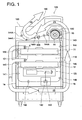
- Fig. 1 is a schematic front view showing a medical recording apparatus to which a cleaning method in the present embodiment can be applied.
- Fig. 2 is a schematic diagram showing an exposure section of the medical recording apparatus in Fig. 1.
- a medical recording apparatus 100 includes a feeding section 110 having a first and second loading sections 11 and 12 for loading and mounting a package of a predetermined number of heat-developing photosensitive films (hereinafter, also referred to as "films"), which are a heat-developing photosensitive material in a sheet-form, and a conveying section 5 for conveying the films sheet by sheet to expose and develop the films.
- films heat-developing photosensitive films
- the apparatus 100 further includes an exposure section 120 for exposing the films supplied from the feeding section 110 and forming latent images, a heat-development section 130 for heat-developing the films formed with the latent images, and a cooling-and-conveying section 150 which has densitometer 200 for obtaining density data by measuring the density of developed films and has conveying rollers 144A.
- Films in different sizes can be respectively loaded in the first and second loading sections 11 and 12 of the feeding section 110.
- films are conveyed one by one in arrow direction (1) by the conveying section 5 and pairs of conveying rollers 139, 140, and 141.
- the pairs of conveying rollers 139, 140, and 141 construct a first conveying unit that conveys the films downward to the exposure section 120.
- each film is horizontally conveyed in arrow direction (2) by pairs of rollers 142 and sub-scanned while a latent image is formed by irradiating laser beams on the film, according to diagnosis image signals in the exposure section 120.
- pairs of conveying rollers 146, 145, 144, and 143 convey the film in arrow direction (3).
- the pairs of conveying rollers 146, 145, 144, and 143 construct a second conveying unit to convey the film formed with the latent image upward toward the heat-development section 130.
- the latent image of the film is visualized by the heat-development section 130, conveyed to arrow direction (4) by pairs of conveying rollers 144A, cooled by the cooling-and conveying section 150, and ejected to an ejection section 160.
- the emulsion side F1 (see Fig. 4) of the film faces the right at the position of the pairs of conveying rollers 139, 140, and 141, faces upward at the position of the pairs of conveying rollers 142 of the exposure section 120, and faces the left at the position of the pairs of conveying rollers 146, 145, 144, and 143.
- the exposure section 120 polarizes a laser beams L, which has been intensity modulated according to a diagnosis image signals S, by a rotational polygonal mirror 113, and main scans the film F.
- the exposure section also sub scans the film F in such a manner that the film F is moved relative to the laser beam L in a direction approximately orthogonal to the main scanning direction.
- the latent image is formed in this way on the film F by the use of the laser beam L.
- image data having been output from an external image signal output device 121 is received through a network or the like, and the diagnosis image signal S being the digital signal of the diagnosis image data is converted into an analog signal by a D/A conversion section 122 and input to a modulation section 123 including a modulation circuit.
- the modulation section 123 controls a driver 124 of a laser beam source section 110a, according to the analog signal, and the modulated laser beam L is irradiated from the laser beam source section 110a.
- the laser beam L irradiated from the laser beam source section 110a passes through a lens 112, gets focused by a cylindrical lens 115 only in the up and down direction, and enters the rotational polygonal mirror 113 rotating in arrow direction A', in the figure, as a line image orthogonal to a drive shaft of the mirror.
- the rotational polygonal mirror 113 reflects and polarizes the laser beam L in the main scanning direction, and the polarized laser beam L passes through f ⁇ lens 114 of a combination of two lenses including a cylindrical lens, then gets reflected by a mirror 116 arranged on the optical path, extending in the main scanning direction, and main scans, repeatedly in arrow direction X, a scanning surface 117 of the film F conveyed (sub scanned) by the pairs of conveying rollers 142 in arrow direction Y. Namely, the laser beam L scans the entire area of the scanning surface 117 of the film F.
- the cylindrical lens of the f ⁇ lens 114 focuses the laser beam L having entered, on the scanning surface 117 of the film F only in the sub scanning direction, wherein the distance from the f ⁇ lens 114 to the scanning surface is equal to the focal distance of the entire f ⁇ lens 114.
- the f ⁇ lens 114 including the cylindrical lens and the mirror 116 are provided in the exposure section 120, and the laser beam L is focused on the rotational polygonal mirror 113 only in the sub scanning direction. Therefore, even when the rotational polygonal mirror 113 inclines or its axis deviates, the scanning position by the laser beam L does not deviate in the sub scanning direction on the scanning surface 117 of the film F, allowing it to form scan lines at a constant pitch.
- the rotational polygonal mirror 113 has the advantage of scan stability compared with other optical polarizers such as a galvanometer mirror. In such a manner, a latent image of a diagnosis image based on diagnosis image signal S is formed on the film F.
- the heat-development section 130 in Fig. 130 includes a heat dram 14 serving as a heating member which holds the film F in close contact with its circumferential surface and is capable of heating and rotating the film.
- a heater is arranged which generates heat and is temperature controlled by electrical current flow control.
- several rotatable facing rollers 16 with a smaller diameter than that of the heat dram 14 are provided to be in contact with the heat dram 14, serving as guide members and press members, wherein the rollers 16 are disposed parallel to the heat dram 14, facing it.
- the heat dram 14 conveys the film F formed with the latent image described above in a state of sandwiching the film F with the plural facing rollers 16, while heating and rotating the film F.
- the heat dram 14 forms a latent image on the film F as a visible diagnosis image.
- the lowest heat-development temperature is the lowest temperature at which heat-development of the latent image formed on the film F begins, and is 95 °C or higher, for example.
- the heat-development time period is a time during which the film F is to be maintained at the lowest heat-development temperature or higher so that the latent image of the film F is developed for desired development characteristics.
- Fig 3 is a perspective view showing the main part in the state where the side cover member is released from the housing of the medical recording apparatus in Fig. 1.
- Fig. 4 is a schematic side view of the pairs of conveying rollers 139, 140, and 141 (the first conveying unit) in Fig. 1.
- the first loading section 11, the second loading section 12, and the exposure section 120 are disposed one above another in this order.
- a side cover member 1a and 1b provided on both sides of the housing 101 are fixed to the housing 101 with screws.
- the side cover member 1a is fitted to plural screw holes 1c formed on the housing 101 with screws so that the inside the cover member 1a is light shielded. By releasing the fixing screws, the side cover members 1a and 1b can be removed to open inside the cover members.
- a releasable system including a known locking mechanism and a solenoid for releasing may be employed for the side cover members 1a and 1b, wherein the solenoid is controlled by a controller, not shown, so that the inside of the cover members is automatically released.
- the pair of conveying rollers 140 disposed on the downstream side of the pair of conveying rollers 139 includes a drive roller 140a which is driven rotationally in one rotation direction t and an adhesive roller 140b which is a driven roller, and conveys the film F conveyed from the pair of conveying rollers 139, in direction (1) downward in Figs. 1 and 4.
- an operation lever 147 is fitted to one end of the shaft of the adhesive roller 140b, as shown in Fig. 3, and the operation lever 147 is operated so that the drive roller 140a is rotated.
- the drive roller 140a of the pair of conveying rollers 140 is made of a resin material, and the adhesive roller 140b has adhesion at the roller surface.
- the adhesive roller 140b can be, for example, a butyl rubber adhesive roller, a silicon rubber adhesive roller, a urethane rubber adhesive roller, or a styrene elastomer adhesive roller, but is not limited to these.
- the adhesive roller 140b is disposed inside the housing 101 to come in contact with the emulsion side F1 of the film F. Foreign matters such as dust tend to adhere to the surface of the adhesive roller 140b.
- foreign matters such as dust and the like adhered to the emulsion side F1 of the film F can be effectively removed in such a manner that the adhesive roller 140b contacts with the emulsion side F1.
- the film F having been conveyed from the pair of conveying rollers 140 is turned from the vertical direction to the horizontal direction after the pair of conveying rollers 141 which is disposed downstream side of the pair of conveying rollers 140, and conveyed by the pairs of conveying rollers 142 in the exposure section 120, while being sub scanned.
- a pair of guide members 148 and 149 is arranged on the upstream side of the pair of conveying rollers 140 in such a manner that the guide members face the respective surfaces of the film F being conveyed, thereby preventing dust and the like from adhering to the film F, to the possible extent.
- the guide member 148 is located on the side of the side cover member 1a, and the guide member 149 is located on the side inside the housing 101.
- the guide member 148 is connected to the side cover member 1a at a connection section 148a, wherein when the side cover member 1a is removed, as shown in Fig. 3, the guide member 148 is also removed integrally with the side cover member 1a from the position shown by the solid lines, in Fig. 4, in direction m toward the position shown by the dashed lines.
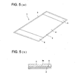
- FIGS. 5A and 5B are respectively a perspective view and a fragmentary enlarged sectional view of the cleaning sheet in the present embodiment.
- the cleaning sheet 1 includes a flexible sheet-formed base 2 in a rectangular shape, an adhesive layer 3a which is provided to make one surface of the flexible sheet-formed base 2 serve as an adhesive surface 3, and auxiliary members 5 and 6 which are provided on the adhesive surface 3, with a predetermined width along the both edges of the flexible sheet-formed base 2, to improve the rigidity of flexible sheet-formed base 2.
- the flexible sheet-formed base 2 can be, for example, a PET sheet, of which thickness may be set to approximately 50 ⁇ m, for example.
- the adhesive layer 3a is formed such that the adhesive surface 3 has an adhesive force greater than that of the surface of the adhesive roller 140b.
- the adhesion of the adhesive surface 3 is preferably five to ten times as strong as that of the surface of the adhesive roller 140b.
- the adhesive layer 3a can be made of an acrylic solvent adhesive, for example, and preferably has an adhesive of approximately 12 to 15 N/25 mm (by JIS Z 0237).
- the auxiliary members 5 and 6 are glued disposed on both edge sides of the adhesive surface 3 of the flexible sheet-formed base 2, sticking out a little from the adhesive surface 3, as shown in Fig. 5A.
- Such a structure enables higher rigidity of the cleaning sheet at the both edge sides, by which the user can grip a front edge part of the cleaning sheet with one hand and insert the sheet into a nip portion of the adhesive roller. Further, in inserting the front edge into the nip portion of the adhesive roller, even repeating insertion twice or three times, for example, the surface of the adhesive surface 3 is not uncovered at the edge portions, and the edge portions are surface-slidable layers of the auxiliary member 5 or 6, thus causing no problem.
- a desired rigidity can of course be obtained by selecting the thicknesses of the auxiliary members 5 and 6 properly. Further, it is also possible to make both sides of the flexible sheet be adhesive surfaces and provide an auxiliary member described above on both sides. Confusing the front side and back side of the flexible sheet-formed base can be prevented in this way. In this case, two auxiliary members function at either edge portion, and accordingly the rigidity increases.
- the auxiliary members 5 and 6 are made, for example, in such a manner that both surfaces of a high quality plain paper sheet are polyethylene laminated and one surface is subjected to peeling. Further, since the auxiliary members 5 and 6 slightly stick out from the adhesive surface 3, it is prevented that the adhesive surface 3 adheres to a part other than the surface of the adhesive roller 140b, when engaging the cleaning sheet with the adhesive roller 140b, and prevented that handling becomes difficult.
- a cover sheet 4 of the same material as the auxiliary members 5 and 6 is arranged between the auxiliary members 5 and 6.
- the cover sheet 4 is peeled off to uncover the adhesive surface 3 when the cleaning sheet 1 is used for cleaning.
- Fig. 6 is a schematic side view showing a state where the pair of conveying rollers 140 in Fig. 4 is cleaned by the cleaning sheet 1 in Fig. 5.
- the user brings the cleaning sheet 1, in Fig. 5, close to the nip section of the pair of conveying rollers 140 such that the auxiliary member 5 is on the adhesive roller 140b side.
- the user grips by hand the auxiliary member 5, having a higher rigidity at the edge portion of the cleaning sheet 1, and thus can easily insert the cleaning sheet 1 toward the nip section of the pair of conveying rollers 140.
- the auxiliary member 5 is sticking out from the adhesive surface 3 during the insertion. Therefore, the front edge of the adhesive surface 3 does not adhere to other portions, enabling easy cleaning.
- the user intermittently rotates the drive roller 140a by the operation lever 147 in one direction t against the load of the drive system including the self holding force of a rotor and a stator of a stepping motor which is the driving source of the drive roller 140a.
- the cleaning sheet 1 is sandwiched by the pair of conveying rollers 140 and moved downward, in Fig. 6, and the adhesive surface 3 of the cleaning sheet 1 is engaged with the adhesive roller 140b to be moved for a predetermined distance being approximately the length of the adhesive surface 3.
- the flexible sheet-formed base 2 can follow the surface of the adhesive roller 140b along the roller axis direction due to the flexible characteristic of the sheet. Therefore, the adhesive surface 3 is engaged with the surface of the adhesive roller 140b uniformly along the roller axis direction, and accordingly wrinkles are not created, allowing uniform cleaning.
- the user rotates the drive roller 140a in reverse direction, sandwiching the cleaning sheet 1 with the pair of conveying rollers 140, and thereby moves the sheet 1 upward, in Fig. 6.
- the user returns the cleaning sheet 1 to where it was while engaging the adhesive surface 3 with the adhesive roller 140b.
- the user repeats this reciprocal operation twice or three times, for example, to clean the entire circumferential surface of the adhesive roller 140b.
- the user rotates the drive roller 140a in reverse direction to separate the edge portion of the flexible sheet-formed base 2 from the nip section of the adhesive roller 140b (in the invention, this operation is referred to as "releasing the engagement between the sheet-formed base and the adhesive roller").
- the user removes the cleaning sheet 1 from the nip section, and thereby cleaning is completed. After removing foreign matters such as dust from the surface of the adhesive roller 140b in this way, when the user closes the cover 1a, it immediately becomes possible to print a diagnosis image.
- a transfer rate from the adhesive roller 140b to the cleaning sheet 1 is higher if the motion speed of the cleaning sheet 1 is lower, for the same adhesive force.
- the user after the user opens the cover corresponding to the adhesive roller of the pair of conveying rollers 140 of the conveying system which is from the feeding section 110 to the exposure section 120, the user preferably moves (rotates) the adhesive roller itself via the operation lever 147 or runs the drive system of the conveying system for motion (rotation), relatively slowly. Further, this is also preferable because power supply to driven components is usually turned off, from the viewpoint of safety, while the cover is open.
- the conveying distance of the cleaning sheet 1 is preferably not shorter than the circumferential length of the adhesive roller 140b.
- the conveying distance is also preferably a length long enough which does not make it difficult to remove the cleaning sheet 1, which could happen when the cleaning sheet continues to be moved manually and the edge of the cleaning sheet 1 goes downstream side too far.
- radiologists or the like to be an operator do not need to directly touch the adhesive roller for maintenance, and only have to insert the front edge of the cleaning sheet 1 to the nip section of the pair of conveying rollers 140. Therefore, irregularities are not created due to wiping by a worker, and uniform cleaning can be achieved.
- an adhesive surface described above is preferably arranged on both surfaces of a flexible sheet-formed base 2 and the auxiliary member is preferably provided at each edge portion of both surfaces.
- adhesive rollers may be arranged for the pairs of conveying rollers 139, 141, and the like, to more effectively remove foreign matters from the emulsion side of a film.
- adhesive rollers similar to those in Fig. 4, may also be disposed on the second conveying unit side (conveying roller pairs 146, 145, 144, and 143), with the same arrangement as that in Fig. 4 to carry out cleaning of the adhesive rollers sufficiently and uniformly by the cleaning sheet 1.
- the cleaning sheet 1 may also be disposed on the second conveying unit side (conveying roller pairs 146, 145, 144, and 143), with the same arrangement as that in Fig. 4 to carry out cleaning of the adhesive rollers sufficiently and uniformly by the cleaning sheet 1.
Landscapes
- Delivering By Means Of Belts And Rollers (AREA)
- Feeding Of Articles By Means Other Than Belts Or Rollers (AREA)
- Projection-Type Copiers In General (AREA)
- Light Sources And Details Of Projection-Printing Devices (AREA)
- Accessory Devices And Overall Control Thereof (AREA)
- Cleaning In General (AREA)
Abstract
Description
(Patent Document 1) TOKKAIHEI No. 05-69654
(Patent Document 2) TOKKAIHEI No. 10-129078
(Patent Document 3) TOKKAI No. 2004-12587
(Patent Document 4) TOKKAIHEI No. 06-328742
(Patent Document 5) TOKKAI No. 2002-220128
(Patent Document 6) TOKKAI No. 2002-337370
(Patent Document 7) TOKKAIHEI No. 10-133309
Claims (10)
- A cleaning method of a medical recording apparatus, wherein the recording apparatus comprises:the method comprising the steps of:a film loading unit for holding a stack of photosensitive sheet films and feeding each sheet film one at a time;a conveying unit for conveying each sheet film, the conveying unit including an adhesive roller which has an adhesive force and works as removing foreign matters from a surface of the sheet film;an exposure unit for forming a latent image corresponding to a diagnosis image signal on the surface of each conveyed sheet film; anda cover unit capable of keeping the film loading unit, the conveying unit, and the exposure unit in a light shielded state, and capable of opening a vicinity of the adhesive roller of the conveying unit,opening the vicinity of the adhesive roller by the cover unit;engaging a cleaning sheet with the adhesive roller, wherein the cleaning sheet has an adhesive surface on at least one side of the cleaning sheet which applies a greater adhesive force than the adhesive force of the adhesive roller;rotating the adhesive roller, while keeping the engagement for conveying the cleaning sheet;transferring the foreign matters from the adhesive roller which have been adhered to the roller in recording on the sheet films, to the surface of the cleaning sheet during the conveyance of the cleaning sheet; andremoving the cleaning sheet with the foreign matters.
- The method of claim 1, wherein the engagement between the cleaning sheet and the adhesive roller is released after the transfer of the foreign matters to the surface of the cleaning sheet.
- The method of claim 1, wherein the adhesive roller further has a nip roller function to convey each sheet film.
- The method of claim 1, wherein the adhesive roller is rotated in normal and reverse directions after the cleaning sheet and the adhesive roller are engaged with each other.
- The method of claim 1, wherein the adhesive roller comes in contact with the surface, of each sheet film one at a time, on which the latent image is formed.
- A cleaning sheet for cleaning an adhesive roller which is provided in a conveying system, of a medical recording apparatus, for conveying a photosensitive film sheet or a photostimulable phosphor sheet and is capable of transferring and removing foreign matters adhered to the film sheet or the phosphor sheet, the cleaning sheet comprising:a flexible sheet-formed base having a flexibility to follow a surface of the adhesive roller along an axis direction of the adhesive roller;an adhesive layer formed on at least one side of the flexible sheet-formed base to make an adhesive surface; andan auxiliary member provided on the adhesive surface along at least one side-edge of the flexible sheet-formed base with a predetermined width for improving rigidity of the flexible sheet-formed base.
- The cleaning sheet of claim 6, wherein a surface of the auxiliary member is slidable on a top surface.
- The cleaning sheet of claim 6, wherein an edge portion of the auxiliary member is sticking out of the adhesive surface.
- The cleaning sheet of claim 6, further comprising a cover sheet that covers the adhesive surface and can be removed so that the adhesive surface can be uncovered when the cleaning sheet is used to perform cleaning.
- The cleaning sheet of claim 6, wherein the cleaning sheet is used as the cleaning sheet in the cleaning method of claim 1 of the medical recording apparatus.
Applications Claiming Priority (2)
| Application Number | Priority Date | Filing Date | Title |
|---|---|---|---|
| JP2004178151A JP2006003515A (en) | 2004-06-16 | 2004-06-16 | Maintenance method and cleaning sheet for medical recording device |
| JP2004178151 | 2004-06-16 |
Publications (2)
| Publication Number | Publication Date |
|---|---|
| EP1607144A2 true EP1607144A2 (en) | 2005-12-21 |
| EP1607144A3 EP1607144A3 (en) | 2006-03-01 |
Family
ID=34979229
Family Applications (1)
| Application Number | Title | Priority Date | Filing Date |
|---|---|---|---|
| EP05253525A Withdrawn EP1607144A3 (en) | 2004-06-16 | 2005-06-08 | Maintenance method of medical recording apparatus and cleaning sheet for surface cleaning roller |
Country Status (3)
| Country | Link |
|---|---|
| US (1) | US20050281585A1 (en) |
| EP (1) | EP1607144A3 (en) |
| JP (1) | JP2006003515A (en) |
Families Citing this family (5)
| Publication number | Priority date | Publication date | Assignee | Title |
|---|---|---|---|---|
| WO2008133078A1 (en) * | 2007-04-17 | 2008-11-06 | Konica Minolta Medical & Graphic, Inc. | Radiation image conversion panel cleaning method, image information reading-out method and image information reading-out device |
| JP2017196588A (en) * | 2016-04-28 | 2017-11-02 | フジコピアン株式会社 | Cleaning sheet |
| JP6779452B2 (en) * | 2016-06-01 | 2020-11-04 | フジコピアン株式会社 | Cleaning sheet |
| JP6779453B2 (en) * | 2016-06-01 | 2020-11-04 | フジコピアン株式会社 | Cleaning sheet |
| JP6872774B2 (en) * | 2016-12-28 | 2021-05-19 | フジコピアン株式会社 | Cleaning sheet |
Citations (8)
| Publication number | Priority date | Publication date | Assignee | Title |
|---|---|---|---|---|
| JPH0569654A (en) | 1991-09-13 | 1993-03-23 | Canon Inc | Superposed body of material to be recorded |
| JPH06328742A (en) | 1993-05-25 | 1994-11-29 | Konica Corp | Laser recording device |
| JPH10129078A (en) | 1996-09-04 | 1998-05-19 | Canon Inc | Cleaning sheet, cleaning method for recording apparatus using the same, and stacked recording material having the same |
| JPH10133309A (en) | 1996-08-08 | 1998-05-22 | Agfa Gevaert Nv | Method for correcting a defect in a radiographic image on a recording member |
| JP2002220128A (en) | 2001-01-25 | 2002-08-06 | Fuji Photo Film Co Ltd | Recorder and method for removing foreign matter in recorder or the like |
| JP2002337370A (en) | 2001-05-17 | 2002-11-27 | Fuji Photo Film Co Ltd | Laser thermal transfer recording method and image receiving sheet |
| JP2004012587A (en) | 2002-06-04 | 2004-01-15 | Fuji Photo Film Co Ltd | Heat developable photosensitive material and its processing method |
| JP2004178151A (en) | 2002-11-26 | 2004-06-24 | Digital Electronics Corp | Display control device, program, and recording medium to which this program is recorded |
Family Cites Families (13)
| Publication number | Priority date | Publication date | Assignee | Title |
|---|---|---|---|---|
| JPH01141078A (en) * | 1987-11-27 | 1989-06-02 | Canon Inc | Cleaning method for cleaning member in image recorder |
| JP2544418B2 (en) * | 1987-12-07 | 1996-10-16 | 三菱重工業株式会社 | Paper dust remover for printing machine |
| US4918464A (en) * | 1988-11-25 | 1990-04-17 | Dai Nippon Insatu Kabushiki Kaisha | Heat-sensitive image transfer type printing apparatus |
| JPH0412948A (en) * | 1990-04-28 | 1992-01-17 | Shinei Kogyo Kk | Cleaning device for sheet material |
| JPH07165343A (en) * | 1993-11-25 | 1995-06-27 | Minolta Co Ltd | Recording device |
| JPH08137019A (en) * | 1994-11-14 | 1996-05-31 | Fuji Photo Film Co Ltd | Photographic film cleaner |
| JPH09230561A (en) * | 1996-02-27 | 1997-09-05 | Noritsu Koki Co Ltd | Roller cleaner and method for cleaning roller of photo processor |
| JPH11202463A (en) * | 1998-01-14 | 1999-07-30 | Nitto Denko Corp | Cleaning tape for transport rollers of photographic photosensitive materials |
| JP3296482B2 (en) * | 1998-08-13 | 2002-07-02 | 富士写真フイルム株式会社 | Thermal development device |
| JP2000078354A (en) * | 1998-08-28 | 2000-03-14 | Asahi Optical Co Ltd | Image reading device |
| US6582141B2 (en) * | 2000-06-27 | 2003-06-24 | Fargo Electronics, Inc. | Card cleaning roller assembly |
| GB0024640D0 (en) * | 2000-10-07 | 2000-11-22 | Ksm Internat Ltd | Substrate cleaning |
| GB0101881D0 (en) * | 2001-01-25 | 2001-03-07 | Ksm Internat Ltd | Cleaning apparatus |
-
2004
- 2004-06-16 JP JP2004178151A patent/JP2006003515A/en active Pending
-
2005
- 2005-06-08 EP EP05253525A patent/EP1607144A3/en not_active Withdrawn
- 2005-06-09 US US11/148,858 patent/US20050281585A1/en not_active Abandoned
Patent Citations (8)
| Publication number | Priority date | Publication date | Assignee | Title |
|---|---|---|---|---|
| JPH0569654A (en) | 1991-09-13 | 1993-03-23 | Canon Inc | Superposed body of material to be recorded |
| JPH06328742A (en) | 1993-05-25 | 1994-11-29 | Konica Corp | Laser recording device |
| JPH10133309A (en) | 1996-08-08 | 1998-05-22 | Agfa Gevaert Nv | Method for correcting a defect in a radiographic image on a recording member |
| JPH10129078A (en) | 1996-09-04 | 1998-05-19 | Canon Inc | Cleaning sheet, cleaning method for recording apparatus using the same, and stacked recording material having the same |
| JP2002220128A (en) | 2001-01-25 | 2002-08-06 | Fuji Photo Film Co Ltd | Recorder and method for removing foreign matter in recorder or the like |
| JP2002337370A (en) | 2001-05-17 | 2002-11-27 | Fuji Photo Film Co Ltd | Laser thermal transfer recording method and image receiving sheet |
| JP2004012587A (en) | 2002-06-04 | 2004-01-15 | Fuji Photo Film Co Ltd | Heat developable photosensitive material and its processing method |
| JP2004178151A (en) | 2002-11-26 | 2004-06-24 | Digital Electronics Corp | Display control device, program, and recording medium to which this program is recorded |
Also Published As
| Publication number | Publication date |
|---|---|
| JP2006003515A (en) | 2006-01-05 |
| US20050281585A1 (en) | 2005-12-22 |
| EP1607144A3 (en) | 2006-03-01 |
Similar Documents
| Publication | Publication Date | Title |
|---|---|---|
| JPH07203133A (en) | Reading / printing device | |
| EP1607144A2 (en) | Maintenance method of medical recording apparatus and cleaning sheet for surface cleaning roller | |
| US6339484B1 (en) | Guide plate assembly and image recording medium transporting apparatus using the assembly | |
| JP2001121785A (en) | Cleaning apparatus and cleaning method | |
| JP2010122316A (en) | Belt device and fixing device | |
| US6244179B1 (en) | Recording apparatus | |
| JP3355135B2 (en) | Image forming device | |
| JP2002287066A (en) | Light beam cutoff device | |
| JPH08115016A (en) | Image forming device | |
| JP2007021927A (en) | Image recording device | |
| JP2001281770A (en) | Automatic dust-proof glass cleaning device and image forming device | |
| US6702490B2 (en) | Image recording apparatus | |
| JP4206028B2 (en) | Printer and image forming method | |
| JP2899118B2 (en) | Sheet material transport device | |
| JP3638104B2 (en) | Image forming apparatus | |
| US6630035B1 (en) | Cleaning unit for recording rotational drum and cleaning method | |
| JPH0993405A (en) | Image reader | |
| US6160608A (en) | Image recording apparatus | |
| JP2002232643A (en) | Original feeder and image forming device provided with this feeder | |
| JP2007183480A (en) | Image forming apparatus | |
| JP2001026127A (en) | Recorder and method for removing foreign matter | |
| JP2005049737A (en) | Image scanner and image forming apparatus | |
| JP3625398B2 (en) | Document conveying apparatus, image reading apparatus including document conveying apparatus, and image forming apparatus including image reading apparatus | |
| JP2000347436A (en) | Image support capable of recording and erasing, image erasing device, and image forming device | |
| JP2006030391A (en) | Cleaning sheet and cleaning method |
Legal Events
| Date | Code | Title | Description |
|---|---|---|---|
| PUAI | Public reference made under article 153(3) epc to a published international application that has entered the european phase |
Free format text: ORIGINAL CODE: 0009012 |
|
| AK | Designated contracting states |
Kind code of ref document: A2 Designated state(s): AT BE BG CH CY CZ DE DK EE ES FI FR GB GR HU IE IS IT LI LT LU MC NL PL PT RO SE SI SK TR |
|
| AX | Request for extension of the european patent |
Extension state: AL BA HR LV MK YU |
|
| PUAL | Search report despatched |
Free format text: ORIGINAL CODE: 0009013 |
|
| AK | Designated contracting states |
Kind code of ref document: A3 Designated state(s): AT BE BG CH CY CZ DE DK EE ES FI FR GB GR HU IE IS IT LI LT LU MC NL PL PT RO SE SI SK TR |
|
| AX | Request for extension of the european patent |
Extension state: AL BA HR LV MK YU |
|
| 17P | Request for examination filed |
Effective date: 20060814 |
|
| 17Q | First examination report despatched |
Effective date: 20060921 |
|
| AKX | Designation fees paid |
Designated state(s): DE FR GB |
|
| RAP1 | Party data changed (applicant data changed or rights of an application transferred) |
Owner name: KONICA MINOLTA MEDICAL & GRAPHIC, INC. |
|
| STAA | Information on the status of an ep patent application or granted ep patent |
Free format text: STATUS: THE APPLICATION IS DEEMED TO BE WITHDRAWN |
|
| 18D | Application deemed to be withdrawn |
Effective date: 20090103 |