EP1606487B1 - Mit pressluft betriebene bohrmaschine mit unabhängigem rotation des bohrwerkzeuges - Google Patents
Mit pressluft betriebene bohrmaschine mit unabhängigem rotation des bohrwerkzeuges Download PDFInfo
- Publication number
- EP1606487B1 EP1606487B1 EP03815272A EP03815272A EP1606487B1 EP 1606487 B1 EP1606487 B1 EP 1606487B1 EP 03815272 A EP03815272 A EP 03815272A EP 03815272 A EP03815272 A EP 03815272A EP 1606487 B1 EP1606487 B1 EP 1606487B1
- Authority
- EP
- European Patent Office
- Prior art keywords
- bushing
- perforator
- piston
- pneumatic
- collar
- Prior art date
- Legal status (The legal status is an assumption and is not a legal conclusion. Google has not performed a legal analysis and makes no representation as to the accuracy of the status listed.)
- Expired - Lifetime
Links
- 239000003638 chemical reducing agent Substances 0.000 claims abstract description 18
- 238000009527 percussion Methods 0.000 claims abstract description 18
- 238000007667 floating Methods 0.000 claims abstract description 14
- 238000005065 mining Methods 0.000 claims abstract description 4
- 239000011435 rock Substances 0.000 claims abstract description 4
- XLYOFNOQVPJJNP-UHFFFAOYSA-N water Substances O XLYOFNOQVPJJNP-UHFFFAOYSA-N 0.000 claims description 4
- 230000006835 compression Effects 0.000 claims description 2
- 238000007906 compression Methods 0.000 claims description 2
- 238000005406 washing Methods 0.000 claims description 2
- 238000009826 distribution Methods 0.000 abstract description 15
- 230000000694 effects Effects 0.000 abstract description 8
- 238000010276 construction Methods 0.000 description 19
- 238000013016 damping Methods 0.000 description 6
- 210000003414 extremity Anatomy 0.000 description 6
- 230000000149 penetrating effect Effects 0.000 description 5
- 210000001364 upper extremity Anatomy 0.000 description 3
- 238000007664 blowing Methods 0.000 description 2
- 230000003247 decreasing effect Effects 0.000 description 2
- 238000012423 maintenance Methods 0.000 description 2
- 238000000034 method Methods 0.000 description 2
- 238000005096 rolling process Methods 0.000 description 2
- 241000180579 Arca Species 0.000 description 1
- 241000287181 Sturnus vulgaris Species 0.000 description 1
- 230000005540 biological transmission Effects 0.000 description 1
- 238000004891 communication Methods 0.000 description 1
- 230000008878 coupling Effects 0.000 description 1
- 238000010168 coupling process Methods 0.000 description 1
- 238000005859 coupling reaction Methods 0.000 description 1
- 238000005520 cutting process Methods 0.000 description 1
- 230000001419 dependent effect Effects 0.000 description 1
- 238000005461 lubrication Methods 0.000 description 1
- 238000003801 milling Methods 0.000 description 1
Images

Classifications
-
- B—PERFORMING OPERATIONS; TRANSPORTING
- B25—HAND TOOLS; PORTABLE POWER-DRIVEN TOOLS; MANIPULATORS
- B25D—PERCUSSIVE TOOLS
- B25D9/00—Portable percussive tools with fluid-pressure drive, i.e. driven directly by fluids, e.g. having several percussive tool bits operated simultaneously
- B25D9/06—Means for driving the impulse member
- B25D9/08—Means for driving the impulse member comprising a built-in air compressor, i.e. the tool being driven by air pressure
-
- B—PERFORMING OPERATIONS; TRANSPORTING
- B25—HAND TOOLS; PORTABLE POWER-DRIVEN TOOLS; MANIPULATORS
- B25D—PERCUSSIVE TOOLS
- B25D16/00—Portable percussive machines with superimposed rotation, the rotational movement of the output shaft of a motor being modified to generate axial impacts on the tool bit
-
- B—PERFORMING OPERATIONS; TRANSPORTING
- B25—HAND TOOLS; PORTABLE POWER-DRIVEN TOOLS; MANIPULATORS
- B25D—PERCUSSIVE TOOLS
- B25D9/00—Portable percussive tools with fluid-pressure drive, i.e. driven directly by fluids, e.g. having several percussive tool bits operated simultaneously
- B25D9/14—Control devices for the reciprocating piston
- B25D9/16—Valve arrangements therefor
- B25D9/20—Valve arrangements therefor involving a tubular-type slide valve
Definitions
- the invention is referring to a pneumatic perforator with independent rotation of the drill, meant for rock perforation in the mining activity.
- a disadvantage of all mentioned distribution systems is that in the final part of the active course in front of the piston is generated an air bag (the counter-pressure) which value is attempting to equal the value of the air pressure compressed in the network before the moment of percussion.
- the counter-pressure is having a negative effect of damping of the piston blow decreasing in this way the perforation speed.
- a perforator for rock mining with simultaneously rotation and percussion with the distribution realized by the tail of the piston is known for example from the US4429752A .
- the problem solved by invention is to realize a pneumatic perforator with independent rotation of the drill, having a small specific consumption of compressed air, increased perforation speed, simplified construction with an easier maintenance in exploitation.
- the perforator eliminate disadvantages of the known solutions and solve the problem raised by the box distribution system through the piston described by that the extremity of the pistons tail, in the back, is on tubular shape with equidistant holes (foreseen in a transversal section) which during the active course are blocked and during the retiring course of the piston are let free by a floating bushing disposed in the respective area; distinguished from the classical constructions as follows in the moment of percussion the circular duct from the valve box ream which is ensuring the compressed air admission for the retiring course of the piston is only partial open by the back extremity of the pistons tail;
- the counter- pressure in front of the piston by not having an important value, the damping of the blow is less important than at the classical constructions, so the blowing energy of the piston increase, implicit increasing the effect of the percussion, only after the percussion moment when the floating bushing is opening the holes from the pistons tail, is starling the massive alimentation with compressed air for realization of the retiring course of the piston; alimentation with compressed air
- the motor of independent rotation machinery of the drill may be positioned at the front extremity of the perforator, being a pneumatic motor with gears located under the driving bushing of the drill and in parallel with this one, the attach pinion of the steering gear of the motor, oriented to the back side of the perforator, constituting the entrance in the 2 nd steps reducer, in the first step the attach pinion is gearing with a internal teeth gear located on the same spindle with the attach pinion of the second step of reducer (their axle being located in the axial vertical plan of the perforator); the second steps pinion is driving the out-going reducers gear, coupled with liner driving bushing which is rotating the plug or the drill.
- the pneumatic motor equipped with gears may be located above the liner driving bushing of the drill and parallel to this one, construction of the independent rotation machinery being identical with the one from the first option proposed for realization of the invention, practical the rotation machinery is positioned rotated with 180° around the axle of driving bushing of the plug or the drill.
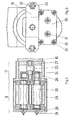
- the pneumatic perforator with independent rotation of the drill, as per the invention, in a first option of realization is equipped with a back-cover A in conformity with the figure 1 , to which is conducted the compressed air through a orifice a; in the back -cover A is fixed the water tube 1 through which is circulating water for washing the perfored hole; in front of the back -cover A is located the repartition valve box B, known itself, having the distribution valve box 2 foreseen with an axial ream; from the back through some ducts b is realized the compressed air feeding in a circular duct c disposed to the front in the distribution box ream 2; the axial ream of the distribution box 2 is communicating to the exterior by the centering portion from the front of the distribution box 2 through ducts d; in the ream of the distribution box 2 is pressed the distribution bushing 3 foresee with a collar on the back; in the bushing ream 3 there is a circular duct oriented to the front, communicating by
- the pneumatic rotating motor E as per the figure 2 is equipped with two gears with the axis parallel to collar bushing spindle 20 , the driving gear 30 of the motor E having the out going, axis notched, oriented to the back of the perforator, to the reducer D, the notched axis of the gear 30 gearing to the interior with the gear equipped with internal teeth 24 (first step of the reducer D ); gears bearing of the motor D is made by rolling bearings for their lubrication is used ball lubricator device 31 . Fastening of the elements A,B, 5, 10 , 26, 28, 19 is made in conformity with figure 3 , with two tightening lifting rods 32 and some nuts 33.
Landscapes
- Engineering & Computer Science (AREA)
- Mechanical Engineering (AREA)
- Physics & Mathematics (AREA)
- Fluid Mechanics (AREA)
- Percussive Tools And Related Accessories (AREA)
- Earth Drilling (AREA)
- Drilling Tools (AREA)
- Perforating, Stamping-Out Or Severing By Means Other Than Cutting (AREA)
- Drilling And Exploitation, And Mining Machines And Methods (AREA)
Claims (3)
- Pneumatischer Durchbohrer mit unabhängiger Drehung des Bohrers zum Durchbohren des Gesteines in der Bergbauindustrie, enthaltend eine Hinterabdeckung (A), einen Verteilungskasten (B), eine Aufschlagmaschine (C) die mit einem Zylinder (5) vorgesehen ist, ein Untersetzungsgetriebe (D) für die Drehmaschinenanlagen, ein pneumatisches Motor (E), und Buchse enthaltend entreibende Backen (16), die das Auslaufventil des Durchbohrers drehen, wo ein Wasserrohr (1) an die Hinterabdeckung (A) befestigt wird, für das umlaufende Wasser um das durchbohrte Loch zu waschen, an der Vorderseite der Hinterabdeckung (A) wo sich der Verteilungskasten (B) befindet, zentriert an der Hinterseite des Zylinders (5) der Aufschlagmaschine (C), das Untersetzungsgetriebe (D) befindet sich an der Vorderseite der Aufschlagmaschine (C) und der pneumatische Motor (E) befindet sich an der Vorderseite des Untersetzungsgetriebe (D), wo der Zylinder (5) mit einem Kolben (6) vorgesehen ist, auf wessen Schaft eine Buchse (7) die mit einem axialen Ausbohrer vorgesehen ist zentriert wird, der an der Hinterseite mit einem Innenkragen (p) endet, Kragen der sich in der Hinterseite des konischen Loches (o) befindet, der geichweit entfert gestellt wird in einem querlaufenden Absatz der Buchse (7), in der Innenseite der Buchse (7) gibt es eine fließende Buchse (8) vorgesehen mit einem Ausbohren der in der Hinterseite mit einem Innenkragen (p) endet und wo, im Benutz, die fließende Buchse (8) öffnet oder schließt die konische Locher (o) auf der Innenseite, wo der kleine Arbeitsweg der fließenden Buchse (8) von dem Kragen (p) der Buchse (7) an der Hinterseite und von der Vorderseite des Bereiches (n) des Kolbenschaft (6) an der Vorderseite begrenzt wird, die fließende Buchse (8) wird an den Endanschlag behalten in Kontakt mit dem Kragen (p) wenn der Durchbohrer von einer sehr schwach Druckfeder (9) gestoppt ist.
- Pneumatischer Durchbohrer nach Anspruch 1, wo der pneumatische Motor mit Zahnradgetriebe (E) unter den Buchse enthaltend antreibende Backen (16) und parallel mit diesen gestellt wird.
- Pneumatischer Durchbohrer nach Anspruch 1, wo der pneumatische Motor mit Zahnradgetriebe (E) über den Buchse enthaltend antreibende Backen (16) und parallel mit diesen gestellt wird.
Applications Claiming Priority (3)
| Application Number | Priority Date | Filing Date | Title |
|---|---|---|---|
| RO200300101 | 2003-02-11 | ||
| ROA200300101A RO121439B1 (ro) | 2003-02-11 | 2003-02-11 | Perforator pneumatic, cu rotire independentă a sfredelului |
| PCT/RO2003/000016 WO2004072430A2 (en) | 2003-02-11 | 2003-12-11 | Pneumatic perforator with independent rotation of the drill |
Publications (2)
| Publication Number | Publication Date |
|---|---|
| EP1606487A2 EP1606487A2 (de) | 2005-12-21 |
| EP1606487B1 true EP1606487B1 (de) | 2009-08-26 |
Family
ID=32867201
Family Applications (1)
| Application Number | Title | Priority Date | Filing Date |
|---|---|---|---|
| EP03815272A Expired - Lifetime EP1606487B1 (de) | 2003-02-11 | 2003-12-11 | Mit pressluft betriebene bohrmaschine mit unabhängigem rotation des bohrwerkzeuges |
Country Status (6)
| Country | Link |
|---|---|
| EP (1) | EP1606487B1 (de) |
| AT (1) | ATE441018T1 (de) |
| AU (1) | AU2003303294A1 (de) |
| DE (1) | DE60329032D1 (de) |
| RO (1) | RO121439B1 (de) |
| WO (1) | WO2004072430A2 (de) |
Families Citing this family (1)
| Publication number | Priority date | Publication date | Assignee | Title |
|---|---|---|---|---|
| EP2242894B1 (de) * | 2008-01-07 | 2014-07-23 | Suk Shin In | Vibrationshammer |
Family Cites Families (3)
| Publication number | Priority date | Publication date | Assignee | Title |
|---|---|---|---|---|
| US2678636A (en) * | 1953-07-14 | 1954-05-18 | Thor Power Tool Co | Air hammer with selective drill steel rotation |
| DE1057037B (de) * | 1955-03-05 | 1959-05-14 | Herbert Jeschke Dr Ing | Pressluftbetriebene Gesteinsschlagbohrmaschine mit zwei koaxial hintereinander angeordneten Zylindern |
| US4429752A (en) * | 1980-01-09 | 1984-02-07 | Joy Manufacturing Company | Pneumatic motor for rock drills and the like |
-
2003
- 2003-02-11 RO ROA200300101A patent/RO121439B1/ro unknown
- 2003-12-11 WO PCT/RO2003/000016 patent/WO2004072430A2/en not_active Ceased
- 2003-12-11 EP EP03815272A patent/EP1606487B1/de not_active Expired - Lifetime
- 2003-12-11 DE DE60329032T patent/DE60329032D1/de not_active Expired - Fee Related
- 2003-12-11 AU AU2003303294A patent/AU2003303294A1/en not_active Abandoned
- 2003-12-11 AT AT03815272T patent/ATE441018T1/de not_active IP Right Cessation
Also Published As
| Publication number | Publication date |
|---|---|
| AU2003303294A1 (en) | 2004-09-06 |
| RO121439B1 (ro) | 2007-05-30 |
| AU2003303294A8 (en) | 2004-09-06 |
| ATE441018T1 (de) | 2009-09-15 |
| EP1606487A2 (de) | 2005-12-21 |
| WO2004072430A3 (en) | 2004-11-11 |
| DE60329032D1 (de) | 2009-10-08 |
| WO2004072430A2 (en) | 2004-08-26 |
Similar Documents
| Publication | Publication Date | Title |
|---|---|---|
| CN103670264B (zh) | 一种双驱动同轴正反向输出螺旋入岩钻机 | |
| CN201791854U (zh) | 无缝钢管缩头机 | |
| EP1606487B1 (de) | Mit pressluft betriebene bohrmaschine mit unabhängigem rotation des bohrwerkzeuges | |
| CN109202131A (zh) | 液压管道钻孔机 | |
| CN103736545B (zh) | 高频破碎锤双马达破碎装置 | |
| CN2047717U (zh) | 高压水射流凿岩机 | |
| CN201405404Y (zh) | 木工钻孔装置 | |
| CN203542480U (zh) | 锤体具有离合机构的冲击式气扳机 | |
| CN201771423U (zh) | 一种新型气动潜孔钻车推进器 | |
| US2208025A (en) | Supporting means for rock drills | |
| CN110984846B (zh) | 一种钻机及其动力头 | |
| CN101576128B (zh) | 啮合式离合器 | |
| CN107664014A (zh) | 一种旋转切削和冲击联动式单体气动锚杆钻机 | |
| CN202804366U (zh) | 毛刺清理工具 | |
| CN207856388U (zh) | 压力冲击自旋转油气分离器 | |
| CN207358213U (zh) | 直角钻削头 | |
| CN202779913U (zh) | 一种气电型动力头装置 | |
| CN209040751U (zh) | 动力头 | |
| CN201241611Y (zh) | 正反转气动钻机 | |
| CN201201025Y (zh) | 皮带齿轮传动节能高速搓丝机 | |
| CN101890468A (zh) | 一种新型动力输入锻压机构 | |
| US1408684A (en) | Percussive tool | |
| CN2164976Y (zh) | 电动混凝土钻 | |
| CN207620708U (zh) | 一种新型水压凿岩机上用的回转装置 | |
| CN205587062U (zh) | 制沙机粉碎滚筒总成 |
Legal Events
| Date | Code | Title | Description |
|---|---|---|---|
| PUAI | Public reference made under article 153(3) epc to a published international application that has entered the european phase |
Free format text: ORIGINAL CODE: 0009012 |
|
| 17P | Request for examination filed |
Effective date: 20050908 |
|
| AK | Designated contracting states |
Kind code of ref document: A2 Designated state(s): AT BE BG CH CY CZ DE DK EE ES FI FR GB GR HU IE IT LI LU MC NL PT RO SE SI SK TR |
|
| AX | Request for extension of the european patent |
Extension state: AL LT LV MK |
|
| DAX | Request for extension of the european patent (deleted) | ||
| REG | Reference to a national code |
Ref country code: HK Ref legal event code: DE Ref document number: 1090401 Country of ref document: HK |
|
| GRAP | Despatch of communication of intention to grant a patent |
Free format text: ORIGINAL CODE: EPIDOSNIGR1 |
|
| GRAS | Grant fee paid |
Free format text: ORIGINAL CODE: EPIDOSNIGR3 |
|
| GRAA | (expected) grant |
Free format text: ORIGINAL CODE: 0009210 |
|
| AK | Designated contracting states |
Kind code of ref document: B1 Designated state(s): AT BE BG CH CY CZ DE DK EE ES FI FR GB GR HU IE IT LI LU MC NL PT RO SE SI SK TR |
|
| REG | Reference to a national code |
Ref country code: GB Ref legal event code: FG4D |
|
| REG | Reference to a national code |
Ref country code: CH Ref legal event code: EP |
|
| REG | Reference to a national code |
Ref country code: IE Ref legal event code: FG4D |
|
| REF | Corresponds to: |
Ref document number: 60329032 Country of ref document: DE Date of ref document: 20091008 Kind code of ref document: P |
|
| PG25 | Lapsed in a contracting state [announced via postgrant information from national office to epo] |
Ref country code: AT Free format text: LAPSE BECAUSE OF FAILURE TO SUBMIT A TRANSLATION OF THE DESCRIPTION OR TO PAY THE FEE WITHIN THE PRESCRIBED TIME-LIMIT Effective date: 20090826 Ref country code: SE Free format text: LAPSE BECAUSE OF FAILURE TO SUBMIT A TRANSLATION OF THE DESCRIPTION OR TO PAY THE FEE WITHIN THE PRESCRIBED TIME-LIMIT Effective date: 20090826 Ref country code: FI Free format text: LAPSE BECAUSE OF FAILURE TO SUBMIT A TRANSLATION OF THE DESCRIPTION OR TO PAY THE FEE WITHIN THE PRESCRIBED TIME-LIMIT Effective date: 20090826 |
|
| NLV1 | Nl: lapsed or annulled due to failure to fulfill the requirements of art. 29p and 29m of the patents act | ||
| PG25 | Lapsed in a contracting state [announced via postgrant information from national office to epo] |
Ref country code: SI Free format text: LAPSE BECAUSE OF FAILURE TO SUBMIT A TRANSLATION OF THE DESCRIPTION OR TO PAY THE FEE WITHIN THE PRESCRIBED TIME-LIMIT Effective date: 20090826 Ref country code: NL Free format text: LAPSE BECAUSE OF FAILURE TO SUBMIT A TRANSLATION OF THE DESCRIPTION OR TO PAY THE FEE WITHIN THE PRESCRIBED TIME-LIMIT Effective date: 20090826 |
|
| PG25 | Lapsed in a contracting state [announced via postgrant information from national office to epo] |
Ref country code: CY Free format text: LAPSE BECAUSE OF FAILURE TO SUBMIT A TRANSLATION OF THE DESCRIPTION OR TO PAY THE FEE WITHIN THE PRESCRIBED TIME-LIMIT Effective date: 20090826 Ref country code: PT Free format text: LAPSE BECAUSE OF FAILURE TO SUBMIT A TRANSLATION OF THE DESCRIPTION OR TO PAY THE FEE WITHIN THE PRESCRIBED TIME-LIMIT Effective date: 20091228 Ref country code: BG Free format text: LAPSE BECAUSE OF FAILURE TO SUBMIT A TRANSLATION OF THE DESCRIPTION OR TO PAY THE FEE WITHIN THE PRESCRIBED TIME-LIMIT Effective date: 20091126 |
|
| PG25 | Lapsed in a contracting state [announced via postgrant information from national office to epo] |
Ref country code: EE Free format text: LAPSE BECAUSE OF FAILURE TO SUBMIT A TRANSLATION OF THE DESCRIPTION OR TO PAY THE FEE WITHIN THE PRESCRIBED TIME-LIMIT Effective date: 20090826 Ref country code: CZ Free format text: LAPSE BECAUSE OF FAILURE TO SUBMIT A TRANSLATION OF THE DESCRIPTION OR TO PAY THE FEE WITHIN THE PRESCRIBED TIME-LIMIT Effective date: 20090826 Ref country code: DK Free format text: LAPSE BECAUSE OF FAILURE TO SUBMIT A TRANSLATION OF THE DESCRIPTION OR TO PAY THE FEE WITHIN THE PRESCRIBED TIME-LIMIT Effective date: 20090826 Ref country code: ES Free format text: LAPSE BECAUSE OF FAILURE TO SUBMIT A TRANSLATION OF THE DESCRIPTION OR TO PAY THE FEE WITHIN THE PRESCRIBED TIME-LIMIT Effective date: 20091207 Ref country code: RO Free format text: LAPSE BECAUSE OF FAILURE TO SUBMIT A TRANSLATION OF THE DESCRIPTION OR TO PAY THE FEE WITHIN THE PRESCRIBED TIME-LIMIT Effective date: 20090826 |
|
| PGFP | Annual fee paid to national office [announced via postgrant information from national office to epo] |
Ref country code: GB Payment date: 20091110 Year of fee payment: 7 |
|
| PG25 | Lapsed in a contracting state [announced via postgrant information from national office to epo] |
Ref country code: SK Free format text: LAPSE BECAUSE OF FAILURE TO SUBMIT A TRANSLATION OF THE DESCRIPTION OR TO PAY THE FEE WITHIN THE PRESCRIBED TIME-LIMIT Effective date: 20090826 |
|
| PG25 | Lapsed in a contracting state [announced via postgrant information from national office to epo] |
Ref country code: BE Free format text: LAPSE BECAUSE OF FAILURE TO SUBMIT A TRANSLATION OF THE DESCRIPTION OR TO PAY THE FEE WITHIN THE PRESCRIBED TIME-LIMIT Effective date: 20090826 |
|
| PLBE | No opposition filed within time limit |
Free format text: ORIGINAL CODE: 0009261 |
|
| STAA | Information on the status of an ep patent application or granted ep patent |
Free format text: STATUS: NO OPPOSITION FILED WITHIN TIME LIMIT |
|
| PG25 | Lapsed in a contracting state [announced via postgrant information from national office to epo] |
Ref country code: MC Free format text: LAPSE BECAUSE OF NON-PAYMENT OF DUE FEES Effective date: 20100701 |
|
| REG | Reference to a national code |
Ref country code: CH Ref legal event code: PL |
|
| 26N | No opposition filed |
Effective date: 20100527 |
|
| REG | Reference to a national code |
Ref country code: FR Ref legal event code: ST Effective date: 20100831 |
|
| PG25 | Lapsed in a contracting state [announced via postgrant information from national office to epo] |
Ref country code: LI Free format text: LAPSE BECAUSE OF NON-PAYMENT OF DUE FEES Effective date: 20091231 Ref country code: CH Free format text: LAPSE BECAUSE OF NON-PAYMENT OF DUE FEES Effective date: 20091231 Ref country code: FR Free format text: LAPSE BECAUSE OF NON-PAYMENT OF DUE FEES Effective date: 20091231 Ref country code: GR Free format text: LAPSE BECAUSE OF FAILURE TO SUBMIT A TRANSLATION OF THE DESCRIPTION OR TO PAY THE FEE WITHIN THE PRESCRIBED TIME-LIMIT Effective date: 20091127 Ref country code: IE Free format text: LAPSE BECAUSE OF NON-PAYMENT OF DUE FEES Effective date: 20091211 |
|
| PG25 | Lapsed in a contracting state [announced via postgrant information from national office to epo] |
Ref country code: DE Free format text: LAPSE BECAUSE OF NON-PAYMENT OF DUE FEES Effective date: 20100701 |
|
| PG25 | Lapsed in a contracting state [announced via postgrant information from national office to epo] |
Ref country code: IT Free format text: LAPSE BECAUSE OF FAILURE TO SUBMIT A TRANSLATION OF THE DESCRIPTION OR TO PAY THE FEE WITHIN THE PRESCRIBED TIME-LIMIT Effective date: 20090826 |
|
| PG25 | Lapsed in a contracting state [announced via postgrant information from national office to epo] |
Ref country code: LU Free format text: LAPSE BECAUSE OF NON-PAYMENT OF DUE FEES Effective date: 20091211 |
|
| PG25 | Lapsed in a contracting state [announced via postgrant information from national office to epo] |
Ref country code: HU Free format text: LAPSE BECAUSE OF FAILURE TO SUBMIT A TRANSLATION OF THE DESCRIPTION OR TO PAY THE FEE WITHIN THE PRESCRIBED TIME-LIMIT Effective date: 20100227 |
|
| GBPC | Gb: european patent ceased through non-payment of renewal fee |
Effective date: 20101211 |
|
| PG25 | Lapsed in a contracting state [announced via postgrant information from national office to epo] |
Ref country code: TR Free format text: LAPSE BECAUSE OF FAILURE TO SUBMIT A TRANSLATION OF THE DESCRIPTION OR TO PAY THE FEE WITHIN THE PRESCRIBED TIME-LIMIT Effective date: 20090826 |
|
| PG25 | Lapsed in a contracting state [announced via postgrant information from national office to epo] |
Ref country code: GB Free format text: LAPSE BECAUSE OF NON-PAYMENT OF DUE FEES Effective date: 20101211 |