EP1605865B1 - Stent avec stratification composite d'un film mince - Google Patents
Stent avec stratification composite d'un film mince Download PDFInfo
- Publication number
- EP1605865B1 EP1605865B1 EP04757547A EP04757547A EP1605865B1 EP 1605865 B1 EP1605865 B1 EP 1605865B1 EP 04757547 A EP04757547 A EP 04757547A EP 04757547 A EP04757547 A EP 04757547A EP 1605865 B1 EP1605865 B1 EP 1605865B1
- Authority
- EP
- European Patent Office
- Prior art keywords
- membrane
- inches
- implant
- bonding layer
- range
- Prior art date
- Legal status (The legal status is an assumption and is not a legal conclusion. Google has not performed a legal analysis and makes no representation as to the accuracy of the status listed.)
- Expired - Lifetime
Links
- 239000002131 composite material Substances 0.000 title claims description 107
- 239000010409 thin film Substances 0.000 title description 4
- 239000012528 membrane Substances 0.000 claims abstract description 171
- 239000011148 porous material Substances 0.000 claims abstract description 79
- 229920000295 expanded polytetrafluoroethylene Polymers 0.000 claims description 45
- -1 polyethylene Polymers 0.000 claims description 24
- 230000001413 cellular effect Effects 0.000 claims description 19
- 230000002829 reductive effect Effects 0.000 claims description 18
- 239000004698 Polyethylene Substances 0.000 claims description 17
- 238000002513 implantation Methods 0.000 claims description 12
- 229920000573 polyethylene Polymers 0.000 claims description 12
- 238000005520 cutting process Methods 0.000 claims description 5
- 239000004744 fabric Substances 0.000 abstract description 19
- 239000007943 implant Substances 0.000 description 186
- 239000000463 material Substances 0.000 description 98
- 210000005248 left atrial appendage Anatomy 0.000 description 76
- 238000003475 lamination Methods 0.000 description 74
- 238000000034 method Methods 0.000 description 48
- 238000002347 injection Methods 0.000 description 42
- 239000007924 injection Substances 0.000 description 42
- 230000003073 embolic effect Effects 0.000 description 41
- 230000004888 barrier function Effects 0.000 description 26
- 208000025339 heart septal defect Diseases 0.000 description 18
- 230000008384 membrane barrier Effects 0.000 description 17
- 239000002872 contrast media Substances 0.000 description 16
- 229940039231 contrast media Drugs 0.000 description 16
- 206010003658 Atrial Fibrillation Diseases 0.000 description 15
- 238000002594 fluoroscopy Methods 0.000 description 15
- 208000007536 Thrombosis Diseases 0.000 description 14
- 238000011068 loading method Methods 0.000 description 14
- 239000000306 component Substances 0.000 description 13
- 229910052751 metal Inorganic materials 0.000 description 12
- 239000002184 metal Substances 0.000 description 12
- 230000033001 locomotion Effects 0.000 description 11
- 238000000576 coating method Methods 0.000 description 10
- 238000002844 melting Methods 0.000 description 10
- 230000008018 melting Effects 0.000 description 10
- 239000011248 coating agent Substances 0.000 description 9
- 238000010276 construction Methods 0.000 description 9
- 239000003550 marker Substances 0.000 description 9
- 238000013508 migration Methods 0.000 description 9
- 230000005012 migration Effects 0.000 description 9
- 230000002792 vascular Effects 0.000 description 9
- 239000012530 fluid Substances 0.000 description 8
- 238000004519 manufacturing process Methods 0.000 description 8
- 239000003381 stabilizer Substances 0.000 description 8
- 208000006011 Stroke Diseases 0.000 description 7
- 239000000853 adhesive Substances 0.000 description 7
- 230000001070 adhesive effect Effects 0.000 description 7
- 210000004369 blood Anatomy 0.000 description 7
- 239000008280 blood Substances 0.000 description 7
- 238000004891 communication Methods 0.000 description 7
- 230000007547 defect Effects 0.000 description 7
- 229940079593 drug Drugs 0.000 description 7
- 239000003814 drug Substances 0.000 description 7
- 238000003698 laser cutting Methods 0.000 description 7
- 229910001000 nickel titanium Inorganic materials 0.000 description 7
- 230000004323 axial length Effects 0.000 description 6
- 230000015572 biosynthetic process Effects 0.000 description 6
- 230000017531 blood circulation Effects 0.000 description 6
- 230000006835 compression Effects 0.000 description 6
- 238000007906 compression Methods 0.000 description 6
- 230000000087 stabilizing effect Effects 0.000 description 6
- 208000008883 Patent Foramen Ovale Diseases 0.000 description 5
- 230000001746 atrial effect Effects 0.000 description 5
- 208000013914 atrial heart septal defect Diseases 0.000 description 5
- 230000008878 coupling Effects 0.000 description 5
- 238000010168 coupling process Methods 0.000 description 5
- 238000005859 coupling reaction Methods 0.000 description 5
- 208000003278 patent ductus arteriosus Diseases 0.000 description 5
- 239000010935 stainless steel Substances 0.000 description 5
- 229910001220 stainless steel Inorganic materials 0.000 description 5
- 208000035478 Interatrial communication Diseases 0.000 description 4
- 206010003664 atrial septal defect Diseases 0.000 description 4
- 239000000835 fiber Substances 0.000 description 4
- 230000006870 function Effects 0.000 description 4
- 230000001788 irregular Effects 0.000 description 4
- 210000005246 left atrium Anatomy 0.000 description 4
- HLXZNVUGXRDIFK-UHFFFAOYSA-N nickel titanium Chemical compound [Ti].[Ti].[Ti].[Ti].[Ti].[Ti].[Ti].[Ti].[Ti].[Ti].[Ti].[Ni].[Ni].[Ni].[Ni].[Ni].[Ni].[Ni].[Ni].[Ni].[Ni].[Ni].[Ni].[Ni].[Ni] HLXZNVUGXRDIFK-UHFFFAOYSA-N 0.000 description 4
- 230000036961 partial effect Effects 0.000 description 4
- 238000012800 visualization Methods 0.000 description 4
- 238000003466 welding Methods 0.000 description 4
- FAPWRFPIFSIZLT-UHFFFAOYSA-M Sodium chloride Chemical compound [Na+].[Cl-] FAPWRFPIFSIZLT-UHFFFAOYSA-M 0.000 description 3
- HZEWFHLRYVTOIW-UHFFFAOYSA-N [Ti].[Ni] Chemical compound [Ti].[Ni] HZEWFHLRYVTOIW-UHFFFAOYSA-N 0.000 description 3
- 210000003484 anatomy Anatomy 0.000 description 3
- 230000008901 benefit Effects 0.000 description 3
- 230000010261 cell growth Effects 0.000 description 3
- 230000007246 mechanism Effects 0.000 description 3
- 238000012986 modification Methods 0.000 description 3
- 230000004048 modification Effects 0.000 description 3
- 239000002245 particle Substances 0.000 description 3
- 239000005020 polyethylene terephthalate Substances 0.000 description 3
- 229920000642 polymer Polymers 0.000 description 3
- 229920001296 polysiloxane Polymers 0.000 description 3
- 238000007789 sealing Methods 0.000 description 3
- 239000011780 sodium chloride Substances 0.000 description 3
- 238000013112 stability test Methods 0.000 description 3
- 229920002554 vinyl polymer Polymers 0.000 description 3
- 206010014498 Embolic stroke Diseases 0.000 description 2
- 239000000020 Nitrocellulose Substances 0.000 description 2
- 239000004696 Poly ether ether ketone Substances 0.000 description 2
- 229920002614 Polyether block amide Polymers 0.000 description 2
- PPBRXRYQALVLMV-UHFFFAOYSA-N Styrene Chemical compound C=CC1=CC=CC=C1 PPBRXRYQALVLMV-UHFFFAOYSA-N 0.000 description 2
- 208000001910 Ventricular Heart Septal Defects Diseases 0.000 description 2
- FJWGYAHXMCUOOM-QHOUIDNNSA-N [(2s,3r,4s,5r,6r)-2-[(2r,3r,4s,5r,6s)-4,5-dinitrooxy-2-(nitrooxymethyl)-6-[(2r,3r,4s,5r,6s)-4,5,6-trinitrooxy-2-(nitrooxymethyl)oxan-3-yl]oxyoxan-3-yl]oxy-3,5-dinitrooxy-6-(nitrooxymethyl)oxan-4-yl] nitrate Chemical compound O([C@@H]1O[C@@H]([C@H]([C@H](O[N+]([O-])=O)[C@H]1O[N+]([O-])=O)O[C@H]1[C@@H]([C@@H](O[N+]([O-])=O)[C@H](O[N+]([O-])=O)[C@@H](CO[N+]([O-])=O)O1)O[N+]([O-])=O)CO[N+](=O)[O-])[C@@H]1[C@@H](CO[N+]([O-])=O)O[C@@H](O[N+]([O-])=O)[C@H](O[N+]([O-])=O)[C@H]1O[N+]([O-])=O FJWGYAHXMCUOOM-QHOUIDNNSA-N 0.000 description 2
- TZCXTZWJZNENPQ-UHFFFAOYSA-L barium sulfate Chemical compound [Ba+2].[O-]S([O-])(=O)=O TZCXTZWJZNENPQ-UHFFFAOYSA-L 0.000 description 2
- 239000011324 bead Substances 0.000 description 2
- 230000000903 blocking effect Effects 0.000 description 2
- 238000005219 brazing Methods 0.000 description 2
- 230000000747 cardiac effect Effects 0.000 description 2
- 229920002678 cellulose Polymers 0.000 description 2
- 239000001913 cellulose Substances 0.000 description 2
- 210000000038 chest Anatomy 0.000 description 2
- 230000000295 complement effect Effects 0.000 description 2
- 239000004035 construction material Substances 0.000 description 2
- 238000013461 design Methods 0.000 description 2
- 238000002592 echocardiography Methods 0.000 description 2
- 210000001105 femoral artery Anatomy 0.000 description 2
- 239000002657 fibrous material Substances 0.000 description 2
- HYBBIBNJHNGZAN-UHFFFAOYSA-N furfural Chemical compound O=CC1=CC=CO1 HYBBIBNJHNGZAN-UHFFFAOYSA-N 0.000 description 2
- 238000010438 heat treatment Methods 0.000 description 2
- 230000023597 hemostasis Effects 0.000 description 2
- 230000005847 immunogenicity Effects 0.000 description 2
- 230000014759 maintenance of location Effects 0.000 description 2
- 230000013011 mating Effects 0.000 description 2
- 229920001179 medium density polyethylene Polymers 0.000 description 2
- 239000004701 medium-density polyethylene Substances 0.000 description 2
- 229920001220 nitrocellulos Polymers 0.000 description 2
- 230000035699 permeability Effects 0.000 description 2
- 229920003229 poly(methyl methacrylate) Polymers 0.000 description 2
- 229920001707 polybutylene terephthalate Polymers 0.000 description 2
- 229920002530 polyetherether ketone Polymers 0.000 description 2
- 229920000139 polyethylene terephthalate Polymers 0.000 description 2
- 239000004926 polymethyl methacrylate Substances 0.000 description 2
- 229920002223 polystyrene Polymers 0.000 description 2
- 229920002635 polyurethane Polymers 0.000 description 2
- 239000004814 polyurethane Substances 0.000 description 2
- 230000009467 reduction Effects 0.000 description 2
- 230000000717 retained effect Effects 0.000 description 2
- 238000004904 shortening Methods 0.000 description 2
- 239000007787 solid Substances 0.000 description 2
- 238000001356 surgical procedure Methods 0.000 description 2
- 238000012360 testing method Methods 0.000 description 2
- 230000002885 thrombogenetic effect Effects 0.000 description 2
- 210000003462 vein Anatomy 0.000 description 2
- 210000002620 vena cava superior Anatomy 0.000 description 2
- 230000002861 ventricular Effects 0.000 description 2
- 201000003130 ventricular septal defect Diseases 0.000 description 2
- PZWQOGNTADJZGH-SNAWJCMRSA-N (2e)-2-methylpenta-2,4-dienoic acid Chemical compound OC(=O)C(/C)=C/C=C PZWQOGNTADJZGH-SNAWJCMRSA-N 0.000 description 1
- QLZJUIZVJLSNDD-UHFFFAOYSA-N 2-(2-methylidenebutanoyloxy)ethyl 2-methylidenebutanoate Chemical compound CCC(=C)C(=O)OCCOC(=O)C(=C)CC QLZJUIZVJLSNDD-UHFFFAOYSA-N 0.000 description 1
- PYSRRFNXTXNWCD-UHFFFAOYSA-N 3-(2-phenylethenyl)furan-2,5-dione Chemical compound O=C1OC(=O)C(C=CC=2C=CC=CC=2)=C1 PYSRRFNXTXNWCD-UHFFFAOYSA-N 0.000 description 1
- WSSSPWUEQFSQQG-UHFFFAOYSA-N 4-methyl-1-pentene Chemical compound CC(C)CC=C WSSSPWUEQFSQQG-UHFFFAOYSA-N 0.000 description 1
- NLHHRLWOUZZQLW-UHFFFAOYSA-N Acrylonitrile Chemical compound C=CC#N NLHHRLWOUZZQLW-UHFFFAOYSA-N 0.000 description 1
- 208000031104 Arterial Occlusive disease Diseases 0.000 description 1
- 208000037260 Atherosclerotic Plaque Diseases 0.000 description 1
- 229920008347 Cellulose acetate propionate Polymers 0.000 description 1
- DQEFEBPAPFSJLV-UHFFFAOYSA-N Cellulose propionate Chemical compound CCC(=O)OCC1OC(OC(=O)CC)C(OC(=O)CC)C(OC(=O)CC)C1OC1C(OC(=O)CC)C(OC(=O)CC)C(OC(=O)CC)C(COC(=O)CC)O1 DQEFEBPAPFSJLV-UHFFFAOYSA-N 0.000 description 1
- 229920002284 Cellulose triacetate Polymers 0.000 description 1
- VEXZGXHMUGYJMC-UHFFFAOYSA-M Chloride anion Chemical compound [Cl-] VEXZGXHMUGYJMC-UHFFFAOYSA-M 0.000 description 1
- 239000004801 Chlorinated PVC Substances 0.000 description 1
- 239000004709 Chlorinated polyethylene Substances 0.000 description 1
- 102000008186 Collagen Human genes 0.000 description 1
- 108010035532 Collagen Proteins 0.000 description 1
- 229920004934 Dacron® Polymers 0.000 description 1
- 208000005189 Embolism Diseases 0.000 description 1
- 239000001856 Ethyl cellulose Substances 0.000 description 1
- ZZSNKZQZMQGXPY-UHFFFAOYSA-N Ethyl cellulose Chemical compound CCOCC1OC(OC)C(OCC)C(OCC)C1OC1C(O)C(O)C(OC)C(CO)O1 ZZSNKZQZMQGXPY-UHFFFAOYSA-N 0.000 description 1
- 239000004812 Fluorinated ethylene propylene Substances 0.000 description 1
- SXRSQZLOMIGNAQ-UHFFFAOYSA-N Glutaraldehyde Chemical compound O=CCCCC=O SXRSQZLOMIGNAQ-UHFFFAOYSA-N 0.000 description 1
- HTTJABKRGRZYRN-UHFFFAOYSA-N Heparin Chemical compound OC1C(NC(=O)C)C(O)OC(COS(O)(=O)=O)C1OC1C(OS(O)(=O)=O)C(O)C(OC2C(C(OS(O)(=O)=O)C(OC3C(C(O)C(O)C(O3)C(O)=O)OS(O)(=O)=O)C(CO)O2)NS(O)(=O)=O)C(C(O)=O)O1 HTTJABKRGRZYRN-UHFFFAOYSA-N 0.000 description 1
- 206010061216 Infarction Diseases 0.000 description 1
- 229920000877 Melamine resin Polymers 0.000 description 1
- ISWSIDIOOBJBQZ-UHFFFAOYSA-N Phenol Chemical compound OC1=CC=CC=C1 ISWSIDIOOBJBQZ-UHFFFAOYSA-N 0.000 description 1
- 229920003171 Poly (ethylene oxide) Polymers 0.000 description 1
- 239000004952 Polyamide Substances 0.000 description 1
- 239000004962 Polyamide-imide Substances 0.000 description 1
- 229920001153 Polydicyclopentadiene Polymers 0.000 description 1
- 239000004695 Polyether sulfone Substances 0.000 description 1
- 239000004697 Polyetherimide Substances 0.000 description 1
- 239000002202 Polyethylene glycol Substances 0.000 description 1
- 239000004642 Polyimide Substances 0.000 description 1
- 239000004734 Polyphenylene sulfide Substances 0.000 description 1
- 239000004954 Polyphthalamide Substances 0.000 description 1
- 239000004743 Polypropylene Substances 0.000 description 1
- 239000004793 Polystyrene Substances 0.000 description 1
- 239000004372 Polyvinyl alcohol Substances 0.000 description 1
- 229920001756 Polyvinyl chloride acetate Polymers 0.000 description 1
- 208000012287 Prolapse Diseases 0.000 description 1
- 208000025747 Rheumatic disease Diseases 0.000 description 1
- 229920000147 Styrene maleic anhydride Polymers 0.000 description 1
- 239000002174 Styrene-butadiene Substances 0.000 description 1
- 239000004699 Ultra-high molecular weight polyethylene Substances 0.000 description 1
- XSQUKJJJFZCRTK-UHFFFAOYSA-N Urea Chemical compound NC(N)=O XSQUKJJJFZCRTK-UHFFFAOYSA-N 0.000 description 1
- 229920001807 Urea-formaldehyde Polymers 0.000 description 1
- 206010058990 Venous occlusion Diseases 0.000 description 1
- NNLVGZFZQQXQNW-ADJNRHBOSA-N [(2r,3r,4s,5r,6s)-4,5-diacetyloxy-3-[(2s,3r,4s,5r,6r)-3,4,5-triacetyloxy-6-(acetyloxymethyl)oxan-2-yl]oxy-6-[(2r,3r,4s,5r,6s)-4,5,6-triacetyloxy-2-(acetyloxymethyl)oxan-3-yl]oxyoxan-2-yl]methyl acetate Chemical compound O([C@@H]1O[C@@H]([C@H]([C@H](OC(C)=O)[C@H]1OC(C)=O)O[C@H]1[C@@H]([C@@H](OC(C)=O)[C@H](OC(C)=O)[C@@H](COC(C)=O)O1)OC(C)=O)COC(=O)C)[C@@H]1[C@@H](COC(C)=O)O[C@@H](OC(C)=O)[C@H](OC(C)=O)[C@H]1OC(C)=O NNLVGZFZQQXQNW-ADJNRHBOSA-N 0.000 description 1
- 229920002877 acrylic styrene acrylonitrile Polymers 0.000 description 1
- XECAHXYUAAWDEL-UHFFFAOYSA-N acrylonitrile butadiene styrene Chemical compound C=CC=C.C=CC#N.C=CC1=CC=CC=C1 XECAHXYUAAWDEL-UHFFFAOYSA-N 0.000 description 1
- 239000004676 acrylonitrile butadiene styrene Substances 0.000 description 1
- 229920000122 acrylonitrile butadiene styrene Polymers 0.000 description 1
- 229920001923 acrylonitrile-ethylene-styrene Polymers 0.000 description 1
- 229910045601 alloy Inorganic materials 0.000 description 1
- 239000000956 alloy Substances 0.000 description 1
- XYLMUPLGERFSHI-UHFFFAOYSA-N alpha-Methylstyrene Chemical compound CC(=C)C1=CC=CC=C1 XYLMUPLGERFSHI-UHFFFAOYSA-N 0.000 description 1
- 238000002266 amputation Methods 0.000 description 1
- 238000004873 anchoring Methods 0.000 description 1
- 238000002399 angioplasty Methods 0.000 description 1
- 230000002965 anti-thrombogenic effect Effects 0.000 description 1
- 210000000709 aorta Anatomy 0.000 description 1
- 206010003119 arrhythmia Diseases 0.000 description 1
- 230000006793 arrhythmia Effects 0.000 description 1
- 208000021328 arterial occlusion Diseases 0.000 description 1
- 210000001367 artery Anatomy 0.000 description 1
- 230000009286 beneficial effect Effects 0.000 description 1
- JUPQTSLXMOCDHR-UHFFFAOYSA-N benzene-1,4-diol;bis(4-fluorophenyl)methanone Chemical compound OC1=CC=C(O)C=C1.C1=CC(F)=CC=C1C(=O)C1=CC=C(F)C=C1 JUPQTSLXMOCDHR-UHFFFAOYSA-N 0.000 description 1
- 239000000560 biocompatible material Substances 0.000 description 1
- 239000012503 blood component Substances 0.000 description 1
- DQXBYHZEEUGOBF-UHFFFAOYSA-N but-3-enoic acid;ethene Chemical compound C=C.OC(=O)CC=C DQXBYHZEEUGOBF-UHFFFAOYSA-N 0.000 description 1
- NTXGQCSETZTARF-UHFFFAOYSA-N buta-1,3-diene;prop-2-enenitrile Chemical compound C=CC=C.C=CC#N NTXGQCSETZTARF-UHFFFAOYSA-N 0.000 description 1
- LTMGJWZFKVPEBX-UHFFFAOYSA-N buta-1,3-diene;prop-2-enenitrile;prop-2-enoic acid Chemical compound C=CC=C.C=CC#N.OC(=O)C=C LTMGJWZFKVPEBX-UHFFFAOYSA-N 0.000 description 1
- MTAZNLWOLGHBHU-UHFFFAOYSA-N butadiene-styrene rubber Chemical compound C=CC=C.C=CC1=CC=CC=C1 MTAZNLWOLGHBHU-UHFFFAOYSA-N 0.000 description 1
- 239000004202 carbamide Substances 0.000 description 1
- 238000007675 cardiac surgery Methods 0.000 description 1
- 230000002612 cardiopulmonary effect Effects 0.000 description 1
- 229920002301 cellulose acetate Polymers 0.000 description 1
- 229920006217 cellulose acetate butyrate Polymers 0.000 description 1
- 229920006218 cellulose propionate Polymers 0.000 description 1
- 239000000919 ceramic Substances 0.000 description 1
- 230000000739 chaotic effect Effects 0.000 description 1
- 230000003196 chaotropic effect Effects 0.000 description 1
- 239000003795 chemical substances by application Substances 0.000 description 1
- 229920000457 chlorinated polyvinyl chloride Polymers 0.000 description 1
- DHZSIQDUYCWNSB-UHFFFAOYSA-N chloroethene;1,1-dichloroethene Chemical compound ClC=C.ClC(Cl)=C DHZSIQDUYCWNSB-UHFFFAOYSA-N 0.000 description 1
- KRGNPJFAKZHQPS-UHFFFAOYSA-N chloroethene;ethene Chemical group C=C.ClC=C KRGNPJFAKZHQPS-UHFFFAOYSA-N 0.000 description 1
- VFULCJGCTDAKDA-UHFFFAOYSA-N chloroethene;ethene;methyl prop-2-enoate Chemical compound C=C.ClC=C.COC(=O)C=C VFULCJGCTDAKDA-UHFFFAOYSA-N 0.000 description 1
- HGAZMNJKRQFZKS-UHFFFAOYSA-N chloroethene;ethenyl acetate Chemical compound ClC=C.CC(=O)OC=C HGAZMNJKRQFZKS-UHFFFAOYSA-N 0.000 description 1
- BGMUGLZGAAEBFU-UHFFFAOYSA-N chloroethene;methyl prop-2-enoate Chemical compound ClC=C.COC(=O)C=C BGMUGLZGAAEBFU-UHFFFAOYSA-N 0.000 description 1
- 208000007413 cholesterol embolism Diseases 0.000 description 1
- 229920001436 collagen Polymers 0.000 description 1
- 230000001010 compromised effect Effects 0.000 description 1
- 230000008602 contraction Effects 0.000 description 1
- 238000007796 conventional method Methods 0.000 description 1
- 210000004351 coronary vessel Anatomy 0.000 description 1
- 230000006378 damage Effects 0.000 description 1
- 230000003247 decreasing effect Effects 0.000 description 1
- 238000007598 dipping method Methods 0.000 description 1
- 238000011038 discontinuous diafiltration by volume reduction Methods 0.000 description 1
- 238000006073 displacement reaction Methods 0.000 description 1
- 230000000694 effects Effects 0.000 description 1
- 230000005489 elastic deformation Effects 0.000 description 1
- 229910000701 elgiloys (Co-Cr-Ni Alloy) Inorganic materials 0.000 description 1
- 230000008030 elimination Effects 0.000 description 1
- 238000003379 elimination reaction Methods 0.000 description 1
- 210000003743 erythrocyte Anatomy 0.000 description 1
- PNWJXICONNROSM-UHFFFAOYSA-N ethene;prop-2-enenitrile;styrene Chemical compound C=C.C=CC#N.C=CC1=CC=CC=C1 PNWJXICONNROSM-UHFFFAOYSA-N 0.000 description 1
- 229920001249 ethyl cellulose Polymers 0.000 description 1
- 235000019325 ethyl cellulose Nutrition 0.000 description 1
- 239000005038 ethylene vinyl acetate Substances 0.000 description 1
- 229920006244 ethylene-ethyl acrylate Polymers 0.000 description 1
- 239000005042 ethylene-ethyl acrylate Substances 0.000 description 1
- 238000011049 filling Methods 0.000 description 1
- 239000010408 film Substances 0.000 description 1
- 210000003811 finger Anatomy 0.000 description 1
- 238000011010 flushing procedure Methods 0.000 description 1
- IVJISJACKSSFGE-UHFFFAOYSA-N formaldehyde;1,3,5-triazine-2,4,6-triamine Chemical compound O=C.NC1=NC(N)=NC(N)=N1 IVJISJACKSSFGE-UHFFFAOYSA-N 0.000 description 1
- SLGWESQGEUXWJQ-UHFFFAOYSA-N formaldehyde;phenol Chemical compound O=C.OC1=CC=CC=C1 SLGWESQGEUXWJQ-UHFFFAOYSA-N 0.000 description 1
- 239000003292 glue Substances 0.000 description 1
- 210000004013 groin Anatomy 0.000 description 1
- 230000035876 healing Effects 0.000 description 1
- 230000002439 hemostatic effect Effects 0.000 description 1
- 229960002897 heparin Drugs 0.000 description 1
- 229920000669 heparin Polymers 0.000 description 1
- 229920001903 high density polyethylene Polymers 0.000 description 1
- 239000004700 high-density polyethylene Substances 0.000 description 1
- 238000003384 imaging method Methods 0.000 description 1
- 150000003949 imides Chemical class 0.000 description 1
- 238000001727 in vivo Methods 0.000 description 1
- 230000007574 infarction Effects 0.000 description 1
- 238000001802 infusion Methods 0.000 description 1
- 238000001746 injection moulding Methods 0.000 description 1
- 238000003780 insertion Methods 0.000 description 1
- 230000037431 insertion Effects 0.000 description 1
- 238000007917 intracranial administration Methods 0.000 description 1
- 208000028867 ischemia Diseases 0.000 description 1
- 230000000302 ischemic effect Effects 0.000 description 1
- 238000010030 laminating Methods 0.000 description 1
- 230000003902 lesion Effects 0.000 description 1
- 229920000092 linear low density polyethylene Polymers 0.000 description 1
- 239000004707 linear low-density polyethylene Substances 0.000 description 1
- 239000007788 liquid Substances 0.000 description 1
- 229920001684 low density polyethylene Polymers 0.000 description 1
- 239000004702 low-density polyethylene Substances 0.000 description 1
- 238000002483 medication Methods 0.000 description 1
- WSFSSNUMVMOOMR-NJFSPNSNSA-N methanone Chemical compound O=[14CH2] WSFSSNUMVMOOMR-NJFSPNSNSA-N 0.000 description 1
- SMUVTFSHWISULV-UHFFFAOYSA-N methyl 2-methylprop-2-enoate;prop-2-enenitrile Chemical compound C=CC#N.COC(=O)C(C)=C SMUVTFSHWISULV-UHFFFAOYSA-N 0.000 description 1
- 238000002324 minimally invasive surgery Methods 0.000 description 1
- 210000004115 mitral valve Anatomy 0.000 description 1
- 239000000203 mixture Substances 0.000 description 1
- 238000000465 moulding Methods 0.000 description 1
- 230000000926 neurological effect Effects 0.000 description 1
- 230000007935 neutral effect Effects 0.000 description 1
- 230000000149 penetrating effect Effects 0.000 description 1
- 230000002093 peripheral effect Effects 0.000 description 1
- 238000011422 pharmacological therapy Methods 0.000 description 1
- 229920001568 phenolic resin Polymers 0.000 description 1
- XNGIFLGASWRNHJ-UHFFFAOYSA-L phthalate(2-) Chemical compound [O-]C(=O)C1=CC=CC=C1C([O-])=O XNGIFLGASWRNHJ-UHFFFAOYSA-L 0.000 description 1
- 230000000704 physical effect Effects 0.000 description 1
- 229920003227 poly(N-vinyl carbazole) Polymers 0.000 description 1
- 229920000090 poly(aryl ether) Polymers 0.000 description 1
- 229920002493 poly(chlorotrifluoroethylene) Polymers 0.000 description 1
- 229920001643 poly(ether ketone) Polymers 0.000 description 1
- 229920001200 poly(ethylene-vinyl acetate) Polymers 0.000 description 1
- 229920002492 poly(sulfone) Polymers 0.000 description 1
- 229920000058 polyacrylate Polymers 0.000 description 1
- 229920002239 polyacrylonitrile Polymers 0.000 description 1
- 229920002647 polyamide Polymers 0.000 description 1
- 229920002312 polyamide-imide Polymers 0.000 description 1
- 229920001230 polyarylate Polymers 0.000 description 1
- 229920001748 polybutylene Polymers 0.000 description 1
- 239000004417 polycarbonate Substances 0.000 description 1
- 229920000515 polycarbonate Polymers 0.000 description 1
- 239000005023 polychlorotrifluoroethylene (PCTFE) polymer Substances 0.000 description 1
- 229920000728 polyester Polymers 0.000 description 1
- 229920006393 polyether sulfone Polymers 0.000 description 1
- 229920001601 polyetherimide Polymers 0.000 description 1
- 229920001223 polyethylene glycol Polymers 0.000 description 1
- 229920002338 polyhydroxyethylmethacrylate Polymers 0.000 description 1
- 229920001721 polyimide Polymers 0.000 description 1
- 239000002861 polymer material Substances 0.000 description 1
- ODGAOXROABLFNM-UHFFFAOYSA-N polynoxylin Chemical compound O=C.NC(N)=O ODGAOXROABLFNM-UHFFFAOYSA-N 0.000 description 1
- 229920006324 polyoxymethylene Polymers 0.000 description 1
- 229920001955 polyphenylene ether Polymers 0.000 description 1
- 229920000069 polyphenylene sulfide Polymers 0.000 description 1
- 229920012287 polyphenylene sulfone Polymers 0.000 description 1
- 229920006375 polyphtalamide Polymers 0.000 description 1
- 229920001155 polypropylene Polymers 0.000 description 1
- 229920001451 polypropylene glycol Polymers 0.000 description 1
- 229920001343 polytetrafluoroethylene Polymers 0.000 description 1
- 239000004810 polytetrafluoroethylene Substances 0.000 description 1
- 229920002689 polyvinyl acetate Polymers 0.000 description 1
- 239000011118 polyvinyl acetate Substances 0.000 description 1
- 229940075065 polyvinyl acetate Drugs 0.000 description 1
- 229920002451 polyvinyl alcohol Polymers 0.000 description 1
- 229940068984 polyvinyl alcohol Drugs 0.000 description 1
- 235000019422 polyvinyl alcohol Nutrition 0.000 description 1
- 239000004800 polyvinyl chloride Substances 0.000 description 1
- 229920000915 polyvinyl chloride Polymers 0.000 description 1
- 229920002620 polyvinyl fluoride Polymers 0.000 description 1
- 229920002981 polyvinylidene fluoride Polymers 0.000 description 1
- 238000002360 preparation method Methods 0.000 description 1
- 238000003825 pressing Methods 0.000 description 1
- 238000012545 processing Methods 0.000 description 1
- QMRNDFMLWNAFQR-UHFFFAOYSA-N prop-2-enenitrile;prop-2-enoic acid;styrene Chemical compound C=CC#N.OC(=O)C=C.C=CC1=CC=CC=C1 QMRNDFMLWNAFQR-UHFFFAOYSA-N 0.000 description 1
- SCUZVMOVTVSBLE-UHFFFAOYSA-N prop-2-enenitrile;styrene Chemical compound C=CC#N.C=CC1=CC=CC=C1 SCUZVMOVTVSBLE-UHFFFAOYSA-N 0.000 description 1
- 210000001147 pulmonary artery Anatomy 0.000 description 1
- 210000003492 pulmonary vein Anatomy 0.000 description 1
- ZAHRKKWIAAJSAO-UHFFFAOYSA-N rapamycin Natural products COCC(O)C(=C/C(C)C(=O)CC(OC(=O)C1CCCCN1C(=O)C(=O)C2(O)OC(CC(OC)C(=CC=CC=CC(C)CC(C)C(=O)C)C)CCC2C)C(C)CC3CCC(O)C(C3)OC)C ZAHRKKWIAAJSAO-UHFFFAOYSA-N 0.000 description 1
- 238000011084 recovery Methods 0.000 description 1
- 230000003014 reinforcing effect Effects 0.000 description 1
- 230000004044 response Effects 0.000 description 1
- 208000037803 restenosis Diseases 0.000 description 1
- 230000002441 reversible effect Effects 0.000 description 1
- 230000000552 rheumatic effect Effects 0.000 description 1
- 210000005245 right atrium Anatomy 0.000 description 1
- QFJCIRLUMZQUOT-HPLJOQBZSA-N sirolimus Chemical compound C1C[C@@H](O)[C@H](OC)C[C@@H]1C[C@@H](C)[C@H]1OC(=O)[C@@H]2CCCCN2C(=O)C(=O)[C@](O)(O2)[C@H](C)CC[C@H]2C[C@H](OC)/C(C)=C/C=C/C=C/[C@@H](C)C[C@@H](C)C(=O)[C@H](OC)[C@H](O)/C(C)=C/[C@@H](C)C(=O)C1 QFJCIRLUMZQUOT-HPLJOQBZSA-N 0.000 description 1
- 229960002930 sirolimus Drugs 0.000 description 1
- 229910000679 solder Inorganic materials 0.000 description 1
- 238000005476 soldering Methods 0.000 description 1
- 238000005507 spraying Methods 0.000 description 1
- 230000009861 stroke prevention Effects 0.000 description 1
- 229920000638 styrene acrylonitrile Polymers 0.000 description 1
- 239000011115 styrene butadiene Substances 0.000 description 1
- 229920003048 styrene butadiene rubber Polymers 0.000 description 1
- 239000000126 substance Substances 0.000 description 1
- 239000000758 substrate Substances 0.000 description 1
- 239000013589 supplement Substances 0.000 description 1
- 229920001059 synthetic polymer Polymers 0.000 description 1
- 238000007910 systemic administration Methods 0.000 description 1
- KKEYFWRCBNTPAC-UHFFFAOYSA-L terephthalate(2-) Chemical compound [O-]C(=O)C1=CC=C(C([O-])=O)C=C1 KKEYFWRCBNTPAC-UHFFFAOYSA-L 0.000 description 1
- 229920001169 thermoplastic Polymers 0.000 description 1
- 239000004416 thermosoftening plastic Substances 0.000 description 1
- 210000003813 thumb Anatomy 0.000 description 1
- 230000008467 tissue growth Effects 0.000 description 1
- 229920000785 ultra high molecular weight polyethylene Polymers 0.000 description 1
- 229960005080 warfarin Drugs 0.000 description 1
- PJVWKTKQMONHTI-UHFFFAOYSA-N warfarin Chemical compound OC=1C2=CC=CC=C2OC(=O)C=1C(CC(=O)C)C1=CC=CC=C1 PJVWKTKQMONHTI-UHFFFAOYSA-N 0.000 description 1
Images


Classifications
-
- B—PERFORMING OPERATIONS; TRANSPORTING
- B32—LAYERED PRODUCTS
- B32B—LAYERED PRODUCTS, i.e. PRODUCTS BUILT-UP OF STRATA OF FLAT OR NON-FLAT, e.g. CELLULAR OR HONEYCOMB, FORM
- B32B27/00—Layered products comprising a layer of synthetic resin
- B32B27/32—Layered products comprising a layer of synthetic resin comprising polyolefins
- B32B27/322—Layered products comprising a layer of synthetic resin comprising polyolefins comprising halogenated polyolefins, e.g. PTFE
-
- A—HUMAN NECESSITIES
- A61—MEDICAL OR VETERINARY SCIENCE; HYGIENE
- A61B—DIAGNOSIS; SURGERY; IDENTIFICATION
- A61B17/00—Surgical instruments, devices or methods, e.g. tourniquets
- A61B17/0057—Implements for plugging an opening in the wall of a hollow or tubular organ, e.g. for sealing a vessel puncture or closing a cardiac septal defect
-
- A—HUMAN NECESSITIES
- A61—MEDICAL OR VETERINARY SCIENCE; HYGIENE
- A61B—DIAGNOSIS; SURGERY; IDENTIFICATION
- A61B17/00—Surgical instruments, devices or methods, e.g. tourniquets
- A61B17/12—Surgical instruments, devices or methods, e.g. tourniquets for ligaturing or otherwise compressing tubular parts of the body, e.g. blood vessels, umbilical cord
- A61B17/12022—Occluding by internal devices, e.g. balloons or releasable wires
- A61B17/12099—Occluding by internal devices, e.g. balloons or releasable wires characterised by the location of the occluder
- A61B17/12122—Occluding by internal devices, e.g. balloons or releasable wires characterised by the location of the occluder within the heart
-
- A—HUMAN NECESSITIES
- A61—MEDICAL OR VETERINARY SCIENCE; HYGIENE
- A61B—DIAGNOSIS; SURGERY; IDENTIFICATION
- A61B17/00—Surgical instruments, devices or methods, e.g. tourniquets
- A61B17/12—Surgical instruments, devices or methods, e.g. tourniquets for ligaturing or otherwise compressing tubular parts of the body, e.g. blood vessels, umbilical cord
- A61B17/12022—Occluding by internal devices, e.g. balloons or releasable wires
- A61B17/12131—Occluding by internal devices, e.g. balloons or releasable wires characterised by the type of occluding device
- A61B17/12168—Occluding by internal devices, e.g. balloons or releasable wires characterised by the type of occluding device having a mesh structure
- A61B17/12172—Occluding by internal devices, e.g. balloons or releasable wires characterised by the type of occluding device having a mesh structure having a pre-set deployed three-dimensional shape
-
- A—HUMAN NECESSITIES
- A61—MEDICAL OR VETERINARY SCIENCE; HYGIENE
- A61L—METHODS OR APPARATUS FOR STERILISING MATERIALS OR OBJECTS IN GENERAL; DISINFECTION, STERILISATION OR DEODORISATION OF AIR; CHEMICAL ASPECTS OF BANDAGES, DRESSINGS, ABSORBENT PADS OR SURGICAL ARTICLES; MATERIALS FOR BANDAGES, DRESSINGS, ABSORBENT PADS OR SURGICAL ARTICLES
- A61L31/00—Materials for other surgical articles, e.g. stents, stent-grafts, shunts, surgical drapes, guide wires, materials for adhesion prevention, occluding devices, surgical gloves, tissue fixation devices
- A61L31/12—Composite materials, i.e. containing one material dispersed in a matrix of the same or different material
- A61L31/125—Composite materials, i.e. containing one material dispersed in a matrix of the same or different material having a macromolecular matrix
- A61L31/129—Composite materials, i.e. containing one material dispersed in a matrix of the same or different material having a macromolecular matrix containing macromolecular fillers
-
- A—HUMAN NECESSITIES
- A61—MEDICAL OR VETERINARY SCIENCE; HYGIENE
- A61M—DEVICES FOR INTRODUCING MEDIA INTO, OR ONTO, THE BODY; DEVICES FOR TRANSDUCING BODY MEDIA OR FOR TAKING MEDIA FROM THE BODY; DEVICES FOR PRODUCING OR ENDING SLEEP OR STUPOR
- A61M25/00—Catheters; Hollow probes
- A61M25/10—Balloon catheters
-
- B—PERFORMING OPERATIONS; TRANSPORTING
- B32—LAYERED PRODUCTS
- B32B—LAYERED PRODUCTS, i.e. PRODUCTS BUILT-UP OF STRATA OF FLAT OR NON-FLAT, e.g. CELLULAR OR HONEYCOMB, FORM
- B32B27/00—Layered products comprising a layer of synthetic resin
- B32B27/06—Layered products comprising a layer of synthetic resin as the main or only constituent of a layer, which is next to another layer of the same or of a different material
- B32B27/08—Layered products comprising a layer of synthetic resin as the main or only constituent of a layer, which is next to another layer of the same or of a different material of synthetic resin
-
- B—PERFORMING OPERATIONS; TRANSPORTING
- B32—LAYERED PRODUCTS
- B32B—LAYERED PRODUCTS, i.e. PRODUCTS BUILT-UP OF STRATA OF FLAT OR NON-FLAT, e.g. CELLULAR OR HONEYCOMB, FORM
- B32B27/00—Layered products comprising a layer of synthetic resin
- B32B27/12—Layered products comprising a layer of synthetic resin next to a fibrous or filamentary layer
-
- B—PERFORMING OPERATIONS; TRANSPORTING
- B32—LAYERED PRODUCTS
- B32B—LAYERED PRODUCTS, i.e. PRODUCTS BUILT-UP OF STRATA OF FLAT OR NON-FLAT, e.g. CELLULAR OR HONEYCOMB, FORM
- B32B7/00—Layered products characterised by the relation between layers; Layered products characterised by the relative orientation of features between layers, or by the relative values of a measurable parameter between layers, i.e. products comprising layers having different physical, chemical or physicochemical properties; Layered products characterised by the interconnection of layers
- B32B7/04—Interconnection of layers
- B32B7/12—Interconnection of layers using interposed adhesives or interposed materials with bonding properties
-
- A—HUMAN NECESSITIES
- A61—MEDICAL OR VETERINARY SCIENCE; HYGIENE
- A61B—DIAGNOSIS; SURGERY; IDENTIFICATION
- A61B17/00—Surgical instruments, devices or methods, e.g. tourniquets
- A61B2017/00535—Surgical instruments, devices or methods, e.g. tourniquets pneumatically or hydraulically operated
- A61B2017/00557—Surgical instruments, devices or methods, e.g. tourniquets pneumatically or hydraulically operated inflatable
-
- A—HUMAN NECESSITIES
- A61—MEDICAL OR VETERINARY SCIENCE; HYGIENE
- A61B—DIAGNOSIS; SURGERY; IDENTIFICATION
- A61B17/00—Surgical instruments, devices or methods, e.g. tourniquets
- A61B17/0057—Implements for plugging an opening in the wall of a hollow or tubular organ, e.g. for sealing a vessel puncture or closing a cardiac septal defect
- A61B2017/00575—Implements for plugging an opening in the wall of a hollow or tubular organ, e.g. for sealing a vessel puncture or closing a cardiac septal defect for closure at remote site, e.g. closing atrial septum defects
- A61B2017/00579—Barbed implements
-
- A—HUMAN NECESSITIES
- A61—MEDICAL OR VETERINARY SCIENCE; HYGIENE
- A61B—DIAGNOSIS; SURGERY; IDENTIFICATION
- A61B17/00—Surgical instruments, devices or methods, e.g. tourniquets
- A61B17/0057—Implements for plugging an opening in the wall of a hollow or tubular organ, e.g. for sealing a vessel puncture or closing a cardiac septal defect
- A61B2017/00575—Implements for plugging an opening in the wall of a hollow or tubular organ, e.g. for sealing a vessel puncture or closing a cardiac septal defect for closure at remote site, e.g. closing atrial septum defects
- A61B2017/00592—Elastic or resilient implements
-
- A—HUMAN NECESSITIES
- A61—MEDICAL OR VETERINARY SCIENCE; HYGIENE
- A61B—DIAGNOSIS; SURGERY; IDENTIFICATION
- A61B17/00—Surgical instruments, devices or methods, e.g. tourniquets
- A61B17/0057—Implements for plugging an opening in the wall of a hollow or tubular organ, e.g. for sealing a vessel puncture or closing a cardiac septal defect
- A61B2017/00575—Implements for plugging an opening in the wall of a hollow or tubular organ, e.g. for sealing a vessel puncture or closing a cardiac septal defect for closure at remote site, e.g. closing atrial septum defects
- A61B2017/00597—Implements comprising a membrane
-
- A—HUMAN NECESSITIES
- A61—MEDICAL OR VETERINARY SCIENCE; HYGIENE
- A61B—DIAGNOSIS; SURGERY; IDENTIFICATION
- A61B17/00—Surgical instruments, devices or methods, e.g. tourniquets
- A61B17/0057—Implements for plugging an opening in the wall of a hollow or tubular organ, e.g. for sealing a vessel puncture or closing a cardiac septal defect
- A61B2017/00575—Implements for plugging an opening in the wall of a hollow or tubular organ, e.g. for sealing a vessel puncture or closing a cardiac septal defect for closure at remote site, e.g. closing atrial septum defects
- A61B2017/00606—Implements H-shaped in cross-section, i.e. with occluders on both sides of the opening
-
- A—HUMAN NECESSITIES
- A61—MEDICAL OR VETERINARY SCIENCE; HYGIENE
- A61B—DIAGNOSIS; SURGERY; IDENTIFICATION
- A61B17/00—Surgical instruments, devices or methods, e.g. tourniquets
- A61B17/0057—Implements for plugging an opening in the wall of a hollow or tubular organ, e.g. for sealing a vessel puncture or closing a cardiac septal defect
- A61B2017/00575—Implements for plugging an opening in the wall of a hollow or tubular organ, e.g. for sealing a vessel puncture or closing a cardiac septal defect for closure at remote site, e.g. closing atrial septum defects
- A61B2017/00615—Implements with an occluder on one side of the opening and holding means therefor on the other
-
- A—HUMAN NECESSITIES
- A61—MEDICAL OR VETERINARY SCIENCE; HYGIENE
- A61B—DIAGNOSIS; SURGERY; IDENTIFICATION
- A61B17/00—Surgical instruments, devices or methods, e.g. tourniquets
- A61B17/0057—Implements for plugging an opening in the wall of a hollow or tubular organ, e.g. for sealing a vessel puncture or closing a cardiac septal defect
- A61B2017/00575—Implements for plugging an opening in the wall of a hollow or tubular organ, e.g. for sealing a vessel puncture or closing a cardiac septal defect for closure at remote site, e.g. closing atrial septum defects
- A61B2017/00619—Locking means for locking the implement in expanded state
-
- A—HUMAN NECESSITIES
- A61—MEDICAL OR VETERINARY SCIENCE; HYGIENE
- A61B—DIAGNOSIS; SURGERY; IDENTIFICATION
- A61B17/00—Surgical instruments, devices or methods, e.g. tourniquets
- A61B17/0057—Implements for plugging an opening in the wall of a hollow or tubular organ, e.g. for sealing a vessel puncture or closing a cardiac septal defect
- A61B2017/00575—Implements for plugging an opening in the wall of a hollow or tubular organ, e.g. for sealing a vessel puncture or closing a cardiac septal defect for closure at remote site, e.g. closing atrial septum defects
- A61B2017/00623—Introducing or retrieving devices therefor
-
- A—HUMAN NECESSITIES
- A61—MEDICAL OR VETERINARY SCIENCE; HYGIENE
- A61B—DIAGNOSIS; SURGERY; IDENTIFICATION
- A61B17/00—Surgical instruments, devices or methods, e.g. tourniquets
- A61B17/0057—Implements for plugging an opening in the wall of a hollow or tubular organ, e.g. for sealing a vessel puncture or closing a cardiac septal defect
- A61B2017/00575—Implements for plugging an opening in the wall of a hollow or tubular organ, e.g. for sealing a vessel puncture or closing a cardiac septal defect for closure at remote site, e.g. closing atrial septum defects
- A61B2017/00632—Occluding a cavity, i.e. closing a blind opening
-
- A—HUMAN NECESSITIES
- A61—MEDICAL OR VETERINARY SCIENCE; HYGIENE
- A61B—DIAGNOSIS; SURGERY; IDENTIFICATION
- A61B17/00—Surgical instruments, devices or methods, e.g. tourniquets
- A61B2017/00831—Material properties
- A61B2017/00867—Material properties shape memory effect
-
- A—HUMAN NECESSITIES
- A61—MEDICAL OR VETERINARY SCIENCE; HYGIENE
- A61B—DIAGNOSIS; SURGERY; IDENTIFICATION
- A61B17/00—Surgical instruments, devices or methods, e.g. tourniquets
- A61B17/12—Surgical instruments, devices or methods, e.g. tourniquets for ligaturing or otherwise compressing tubular parts of the body, e.g. blood vessels, umbilical cord
- A61B17/12022—Occluding by internal devices, e.g. balloons or releasable wires
- A61B2017/1205—Introduction devices
- A61B2017/12054—Details concerning the detachment of the occluding device from the introduction device
- A61B2017/12095—Threaded connection
-
- A—HUMAN NECESSITIES
- A61—MEDICAL OR VETERINARY SCIENCE; HYGIENE
- A61M—DEVICES FOR INTRODUCING MEDIA INTO, OR ONTO, THE BODY; DEVICES FOR TRANSDUCING BODY MEDIA OR FOR TAKING MEDIA FROM THE BODY; DEVICES FOR PRODUCING OR ENDING SLEEP OR STUPOR
- A61M25/00—Catheters; Hollow probes
- A61M25/10—Balloon catheters
- A61M2025/1043—Balloon catheters with special features or adapted for special applications
- A61M2025/1054—Balloon catheters with special features or adapted for special applications having detachable or disposable balloons
-
- A—HUMAN NECESSITIES
- A61—MEDICAL OR VETERINARY SCIENCE; HYGIENE
- A61M—DEVICES FOR INTRODUCING MEDIA INTO, OR ONTO, THE BODY; DEVICES FOR TRANSDUCING BODY MEDIA OR FOR TAKING MEDIA FROM THE BODY; DEVICES FOR PRODUCING OR ENDING SLEEP OR STUPOR
- A61M2210/00—Anatomical parts of the body
- A61M2210/12—Blood circulatory system
- A61M2210/125—Heart
-
- B—PERFORMING OPERATIONS; TRANSPORTING
- B32—LAYERED PRODUCTS
- B32B—LAYERED PRODUCTS, i.e. PRODUCTS BUILT-UP OF STRATA OF FLAT OR NON-FLAT, e.g. CELLULAR OR HONEYCOMB, FORM
- B32B2535/00—Medical equipment, e.g. bandage, prostheses, catheter
Definitions
- the present invention generally relates to thin film composite laminations used as medical devices.
- Embolic stroke is the nation's third leading killer for adults, and is a major cause of disability. There are over 700,000 strokes per year in the United States alone. Of these, roughly 100,000 are hemorragic, and 600,000 are ischemic (either due to vessel narrowing or to embolism). The most common cause of embolic stroke emanating from the heart is thrombus formation due to atrial fibrillation (AF). Approximately 80,000 strokes per year are attributable to atrial fibrillation. Atrial fibrillation is an arrhythmia of the heart that results in a rapid and chaotic heartbeat that produces lower cardiac output and irregular and turbulent blood flow in the vascular system. There are over five million people worldwide with atrial fibrillation, with about four hundred thousand new cases reported each year. Atrial fibrillation is associated with a 500 percent greater risk of stroke due to the condition. A patient with atrial fibrillation typically has a significantly decreased quality of life due, in part, to the fear of a stroke, and the pharmaceutical regimen necessary to reduce that risk.
- LAA left atrial appendage
- the LAA is a cavity which looks like a small finger or windsock and which is connected to the lateral wall of the left atrium between the mitral valve and the root of the left pulmonary vein.
- the LAA normally contracts with the rest of the left atrium during a normal heart cycle, thus keeping blood from becoming stagnant therein.
- the LAA often fails to contract with any vigor in patients experiencing atrial fibrillation due to the discoordinate electrical signals associated with AF.
- thrombus formation is predisposed to form in the stagnant blood within the LAA.
- Semi-permanently and permanently implantable devices may be used to reduce the risk of thrombus formation due to atrial fibrillation, as well as a variety of other medical conditions.
- One advantage of these devices is their ability to be introduced during minimally invasive procedures through the use of catheters. Catheters having a small cross sectional profile can be used to access remote locations in the patient through the vascular system. The devices delivered with these catheters are generally capable of assuming a compact form that will fit within the catheter.
- a variety of these devices incorporate flexible permeable or semi-permeable membranes. Accordingly, the membrane materials often have a minimal thickness as well as appropriate anti-thrombogenic properties.
- porous fabrics that are attached to supporting structures.
- the physical and chemical properties that make the porous fabrics ideal for use in the vascular system also make them difficult to attach to supporting substrates.
- Porous fabric sheets of ePTFE can be particularly difficult to attach to supporting structures.
- a device with the features of the preamble of claim 1 is disclosed in WO 2002/0111647 .
- a laminated stent-graft suitable for implantation within a medical patient, comprising: a frame, a first membrane, having first membrane pores, a second membrane, having second membrane pores, a mesh bonding layer, having a bonding layer open surface area and bonding layer pores, wherein the first membrane and second membrane are at least partially attached to the mesh bonding layer to form a composite membrane, wherein the composite membrane has a composite membrane open surface area in the range between about 10% and about 50%, and wherein the stent is generally cylindrical and is adjustable from a first configuration having a reduced diameter to a second configuration having an expanded diameter, the stent forming a conduit in the second configuration.
- the first membrane comprises ePTFE. In another embodiment, the first membrane has a thickness in the range of from about 0.001 cm (0.0005 inches) to about 0.25 cm (0.10 inches). In yet another embodiment, the first membrane pores comprise an average pore diameter in the range of from about 1 ⁇ m to about 200 ⁇ m. In another embodiment, the first membrane comprises an internodal distance in the range of from about 10 ⁇ m to about 100 ⁇ m.
- the bonding layer comprises polyethylene.
- the composite membrane has a thickness in the range of from about 0.003 cm (0.001 inches) to about 0.025 cm (0.010 inches).
- an element of a support structure is disposed between the first membrane and the second membrane.
- the composite membrane open surface area is sufficient to facilitate cellular ingrowth and/or cellular attachment.
- the composite membrane has an average thickness within the range of about 0.003 cm (0.001 inches) to about 0.025 cm (0.010 inches).
- an element of the frame is disposed between the first membrane and the second membrane.
- the composite membrane open surface area is sufficient to facilitate cellular ingrowth and/or cellular attachment.
- the composite membrane has an average thickness within the range of about 0.003 cm (0.001 inches) to about 0.025 cm (0.010 inches).
- a biocompatible laminate fabric for use in the present invention including a porous first membrane layer, a porous second membrane layer, and an open mesh bonding layer between the first and second membrane layers.
- the bonding layer holds the first and second membrane layers together by extending into one or more pores of each membrane layer.
- an element of a support structure is disposed between the first and second membrane layers.
- the biocompatible laminate fabric retains sufficient porosity to facilitate cellular ingrowth and/or cellular attachment.
- the biocompatible laminate fabric has an average thickness that in one embodiment is within the range of about 0.003 cm (0.001 inches) to about 0.025 cm (0.010 inches), preferably less than about 0.01 cm (0.005 inches), more preferably less than about 0.008 cm (0.003 inches), in one embodiment is less than about 0.005 cm (0.002 inches), and in yet another embodiment is about 0.0038 cm (0.0015 inches).
- the biocompatible laminate fabric is no more than about three times as thick as the first membrane layer, preferably is no more than about twice as thick as the first membrane layer, is no more than about three times as thick as the second membrane layer, and in another embodiment, is no more than about twice as thick as the second membrane layer.
- the bonding layer has an average thickness before bonding to the first membrane layer within the range of about 0.001 cm (0.0005 inches) to about 0.01 cm (0.005 inches), about 0.002 cm (0.0008 inches) to about 0.01 cm (0.004 inches), about 0.002 cm (0.0009 inches) to about 0.008 cm (0.003 inches), and in another embodiment, about 0.003 cm (0.001 inches) to about 0.005 cm (0.002 inches).
- the bonding layer has an average pore cross section within the range of about 0.01 cm (0.005 inches) to about 0.50 cm (0.200 inches), and in another embodiment, about 0.051 cm (0.020 inches) to about 0.20 cm (0.080 inches). In one embodiment, the bonding layer has an average spacing between adjacent pores within the range of about 0.001 cm (.0005 inches) to about 1.0 cm (0.400 inches). In one embodiment, the bonding layer has an average open surface area within the range of about 10% to about 90, or preferably within the range of about 30% to about 60%.
- the softening point of the bonding layer is within the range of about 38°C (100°F) to about 149°C (300°F), or preferably within the range of about 93°C (200°F) to about 204°C (400°F). In one embodiment, the melting point of the bonding layer is within the range of about 38°C (100°F) to about 149°C (300°F).
- the first membrane layer has an average thickness within the range of about 0.001 cm (0.0005 inches) to about 0.025 cm (0.010 inches), or preferably about 0.003 cm (0.001 inches) to about 0.005 cm (0.002 inches). In one embodiment, the first membrane layer has an average open surface area within the range of about 10% to about 80%, or preferably about 30% to about 60%.
- the softening point of the first membrane layer is within the range of about 66°C (150°F) to about 260°C (500°F), or preferably about 93°C (200°F) to about 204°C (400°F).
- the melting point of the first membrane layer is within the range of about 66°C (150°F) to about 260°C (500°F), or preferably about 93°C (200°F) to about 204°C (400°F).
- the difference between the softening point of at least one of the first and second membrane layers and the softening point of the bonding layer is within the range of about 4°C (25°F) to about 93°C (200°F), or preferably is within the range of about 10°C (50°F) to about 38°C (100°F).
- the bonding layer holds the first and second membrane layers together by extending into one or more pores of each membrane layer.
- an element of the support structure is disposed between the first and second membrane layers.
- the biocompatible laminate fabric retains sufficient porosity to facilitate cellular ingrowth and/or cellular attachment.
- the biocompatible laminate fabric has an average thickness within the range of about 0.003 cm (0.001 inches) to about 0.025 cm (0.010 inches), or preferably less than about 0.008 cm (0.003 inches).
- the method includes heating a first membrane layer, a second membrane layer and an open mesh bonding layer, under pressure, until the bonding layer becomes sufficiently soft that it flows into pores of each of the first and second membrane layers.
- the layers are heated to a temperature that is at least the softening point of the bonding layer but no more than the softening point of the first and second membrane layers. In another embodiment, the layers are heated to a temperature that is within the range of about 38°C (100°F) to about 93°C (200°F). In another embodiment, the layers are heated under a pressure that is sufficient to allow at least some of the bonding layer to flow into at least one of the pores of each of the first and second membrane layers.
- the layers are heated under a pressure that is within the range of about 2 x 10 6 N/m 2 (30 psi) to about 2 x 10 7 N/m 2 (300 psi), and in another embodiment, the layers are heated under pressure for a period of time that is sufficient to allow at least some of the bonding layer to flow into at least one of the pores of each of the first and second membrane layers. In yet another embodiment, the layers are heated under pressure for a period of time that is within the range of about 1 minute to about 5 minutes.
- the method includes the steps of providing an assembly comprising a first membrane layer, a second membrane layer, an open mesh bonding layer, and an element of a support structure disposed between the first and second membrane layers, and heating the assembly under pressure until the bonding layer becomes sufficiently soft that it flows into pores of each of the first and second membrane layers.
- the support structure is a component of an implantable medical device.
- the bonding layer secures the first membrane layer to the support structure by extending into one or more pores of the membrane layer.
- the bonding layer secures the first membrane layer to the support structure by extending around a portion of the support structure and bonding to itself.
- the method includes providing a medical device having a first membrane, a second membrane, and a mesh bonding layer.
- the first membrane has first membrane pores
- the second membrane has second membrane pores
- the mesh bonding layer has a bonding layer open surface area and bonding layer pores.
- the first membrane and second membrane are at least partially attached to the mesh bonding layer to form a composite membrane.
- the method also includes delivering the medical device to a desired treatment location in a patient.
- the composite membrane has a composite membrane open surface area in the range between about 10% and about 50%, and the composite membrane open surface area permits tissue ingrowth through the composite membrane and across at least one of the first and second membranes.
- the composite membrane blocks the passage of embolic material across the composite membrane.
- the desired treatment location is a left atrial appendage, a septal defect, or near an occlusion in a vessel.
- occlusion device 10 which is not part of the invention.
- occlusion as used herein is intended to include devices that block the passage of embolic material of size which is a function of the pore size of the fabric or other membrane, although the device may at least initially permit the passage of whole blood or blood components.
- occlusion as used herein is also intended to include devices that contain embolic material within a volume bounded on at least one side by at least one surface of such device.
- a thin film composite lamination may be used on or to form portions or all of any of a variety of medical devices.
- medical devices include, but are not limited to, vascular implants such as aortic, coronary, peripheral or neurovascular grafts or stent grafts (such as the stent-graft of claim 1 of the invention), occlusion devices such as atrial septal defect (ASD), patent foramen ovale (PFO), ventricular septal defect (VSD) and patent ductus arteriosus (PDA) closure devices, arterial and venous occlusion devices, valve prostheses including the annulus, struts and leaflets, annuloplasty rings, tissue patches, ventricular volume reduction structures, or coverings on any of the foregoing, or other devices as will be appreciated by those of skill in the art.
- vascular implants such as aortic, coronary, peripheral or neurovascular grafts or stent grafts (such as the stent-graft of claim 1 of the invention)
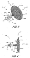
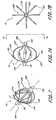
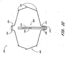
- the occlusion device 10 comprises an occluding member 11 comprising a frame 14 and a barrier 15.
- the frame 14 comprises a plurality of radially outwardly extending spokes 17 each having a length within the range of from about 0.5 cm to about 2 cm from a hub 16. In one example, the spokes have an axial length of about 1.5 cm.
- spokes may be utilized anywhere within the range of from about 3 spokes to about 40 spokes. In some examples, anywhere from about 12 to about 24 spokes are utilized and, 18 spokes are utilized in one example.
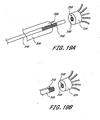
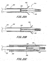
- the spokes are advanceable from a generally axially extending orientation, such as to fit within a tubular introduction catheter, to a radially inclined orientation, as illustrated in FIG. 1 and FIG. 2 , following deployment from the catheter.
- the spokes are biased radially outwardly such that the occlusion member expands to its enlarged, implantation cross-section under its own bias following deployment from the catheter.
- the occlusion member may be enlarged using any of a variety of enlargement structures such as an inflatable balloon, or a catheter for axially shortening the occlusion member, as is discussed further below.
- the spokes comprise a metal such as stainless steel, Nitinol, Elgiloy, or others which can be determined through routine experimentation by those of skill in the art.
- Wires having a circular or rectangular cross-section may be utilized depending upon the manufacturing technique.
- rectangular cross section spokes are cut such as by known laser cutting techniques from tube stock, a portion of which forms the hub 16.
- the barrier 15 may comprise any of a variety of materials, particularly those which facilitate cellular in-growth, such as ePTFE. The suitability of alternate materials for barrier 15 can be determined through routine experimentation by those of skill in the art.
- the barrier 15 may be provided on either one or both axially facing sides of the occlusion member.
- the barrier 15 comprises two layers, with one layer on each side of the frame 14. The two layers may be bonded to each other around the spokes 17 in any of a variety of ways, such as by heat bonding with or without an intermediate bonding layer such as polyethylene or FEP, adhesives, sutures, clips or staples, and other techniques which will be apparent to those of skill in the art in view of the disclosure herein.
- the barrier 15 preferably has a thickness of no more than about 0.008 cm (0.003 inches) and a pore size within the range of from about 5 ⁇ m to about 60 ⁇ m.
- the barrier 15 in one example is securely attached to the frame 14 and retains a sufficient porosity to facilitate cellular ingrowth and/or attachment.
- One method of manufacturing a suitable composite membrane barrier 15 is illustrated in FIGS. 13-16 .
- the barrier 15 includes a first layer or membrane 250 on a first side of the frame 14, a second layer or membrane 252 on a second side of the frame, and a bonding layer 254 on either of the first side or the second side (shown in Fig. 14 as being on the first side). It will be appreciated that the barrier described herein can be used with any of the devices described herein.
- a bonding layer 254 preferably comprises a mesh or other porous structure having an open surface area within the range of from about 10% to about 90%.
- the open surface area is the percentage of the layer's or membrane's area that is open to both sides.
- the term "pores" is intended to have its ordinary meaning as well as a volume within a material through which a gas or liquid may pass. In one embodiment pores have regular shapes, such as cylinders, but in other embodiments, pores have highly irregular shapes, and comprise the open spaces between the fibers of fibrous materials, for example, expanded polytetrafluoroethylene. In another embodiment, the term pores includes the irregularly shaped volumes of open spaces between the fibers of overlapping fibrous materials which are either in contact, or separated by one or more porous intermediate layers, such as an open mesh bonding layer, as described in greater detail below.
- the open surface area may be measure using methods well known to those of skill in the art. For example, in one embodiment, the membrane surface is photographed, imaged, or otherwize visualized, and the open surface area is calculated by dividing the sum of the area of the pores by area of the membrane surface visualized. In one embodiment, such calculations are performed by a computer system, signal processing system, and/or software program. Generally, the open surface area of the mesh is within the range of from about 20% to about 70%, often from about 30% to about 60%, an in some applications, from about 40% to about 50% depending on the desired clinical performance. The optimum percentage of open surface area can be determined for any particular application and for any particular material or combination of materials through routine experimentation by one or ordinary skill in the art based on the disclosures herein.
- the average pore diameter of the bonding layer 254 is preferably within the range of from about 0.01 cm (0.005 inches)to about 0.13 cm (0.050 inches), often from about 0.025 cm (0.010 inches) to about 0.10 cm (0.040 inches), and in some applications from about 0.038 cm (0.015 inches) to about 0.076 cm (0.030 inches) depending on the desired clinical performance, and, in one embodiment, is about 0.051 cm (0.020 inches).
- the diameter is measured in the conventional way.
- the diameter is the average of the distance between opposite vertices (sides).
- the pore diameter is the diameter of a circle having an equivalent area to the area of the actual pore.
- the optimum average pore diameter can be determined for any particular application and for any particular material or combination of materials through routine experimentation by one or ordinary skill in the art based on the disclosure herein.
- the average pore area of bonding layer 254 is within the range of from about 0.00013 cm 2 (0.000020 inched) to about 0.016 cm 2 (0.0025 inches 2 ), often from about 0.00052 cm 2 (0.000079 inches 2 ) to about 0.010 cm 2 (0.0016 inches 2 ), and in some applications from about 0.00114 cm 2 (0.000177 inches 2 ) to about 0.006 cm 2 (0.0009 inches 2 ), depending on the desired clinical performance, and, in one embodiment, is about 0.006 cm 2 (0.0004 inches 2 ).
- the optimum average pore area can be determined for any particular application and for any particular material or combination of materials through routine experimentation by one or ordinary skill in the art based on the disclosure herein.
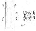
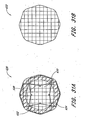
- one structure for a bonding layer 254 is a mesh comprising a first plurality of parallel elements or fibers extending in a first direction, and a second plurality of parallel fibers extending in a second direction which is generally transverse to the first direction.
- the result is to produce a plurality of predictable pores or openings as has been discussed.
- the bonding layer 254 includes one or more bonding strips arranged in a woven or an intersecting pattern.
- the bonding layer 254 includes a sheet of bonding material with windows or spaces where bonding material is not present.
- the mesh may comprise a first plurality of elements extending generally parallel to each other and spaced apart, without a second plurality of transverse elements.
- the bonding layer may alternatively comprise a bead or element of bonding material which extends across the surface of the membrane in a zig zag or sinusoidal pattern.
- the bonding mesh may comprise a bead or element of bonding material which extends in a spiral pattern across the surface of the membrane 250.
- the thickness of the bonding layer 254 can be varied widely, and is generally within the range of from about 0.001 cm (0.0005 inches) to about 0.01 cm (0.005 inches), often from about 0.002 cm (0.0008 inches) to about 0.01 cm (0.004 inches), and in some applications from about 0.002 cm (0.0009 inches) to about 0.008 cm (0.003 inches) depending on the desired clinical performance.
- the bonding layer 254 has a thickness of about 0.003 cm (0.001 inches) to about 0.005 cm (0.002 inches). The optimum thickness can be determined for any particular application and for any particular material or combination of materials through routine experimentation by one or ordinary skill in the art based on the disclosure herein.
- the bonding layer 254 may comprise any of a variety of materials that have either a softening temperature that is no greater than the softening temperature of the layers 250 and 252, or a melting temperature that is no greater than the melting temperature of the layers 250 and 252.
- a softening temperature that is no greater than the softening temperature of the layers 250 and 252
- a melting temperature that is no greater than the melting temperature of the layers 250 and 252.
- the bonding layer 254 is preferably placed adjacent one or both sides of a spoke, stent wall, or other frame element 14.
- the bonding layer 254 and frame 14 layers are then positioned in-between a first membrane 250 and a second membrane 252 to provide a composite membrane stack.
- the first membrane 250 and second membrane 252 may comprise any of a variety of materials and thicknesses, depending upon the desired functional result.
- the membranes 250 and 252 may comprise either the same or different materials, particularly those that facilitate cellular in-growth in a device such as an LAA occlusion device.
- a single membrane 250 is used.
- the membrane 250 is secured to a bonding layer 254.
- the resulting two layer stack is positioned adjacent a support structure such as struts on an implantable device.
- the bonding layer 254 is attached to the support structure in any of a variety of ways, such as by melting the bonding layer 254 into a porous surface on the support, or bonding the bonding layer 254 to a compatible surface such as a polymeric support structure, a ceramic structure, or a metallic structure having a compatible bonding layer thereon.
- the membrane 250 having a bonding layer 254 thereon may be positioned with the bonding layer 254 against a support structure.
- the membrane and bonding layer laminate may then be wrapped or pinched around a strut or other portion of the support structure, such that the bonding layer 254 surrounds at least a portion of a strut or other support component and is bonded to itself.
- the materials that may be included in the bonding layer 254 and/or the membranes 250, 252 for an embodiment of the present invention will depend upon the desired performance of the device (e.g., antigenicity, thrombogenicity, immunogenicity), physical characteristics (e.g., thickness, flexibility, elasticity, porosity), and manufacturing considerations (e.g., bondability, extrudability), as will be apparent to those of skill in the art.
- Materials that may be used alone or in combination include: Acrylonitrile, Acrylonitrile Butadiene, Acrylonitrile Butadiene Acrylate, Acrylonitrile Butadiene Styrene, Acrylonitrile Ethylene Styrene, Acrylonitrile Methyl Methacrylate, Acrylonitrile Styrene Acrylate, Cellulose Acetate, Cellulose Acetate Butyrate, Cellulose Acetate Propionate, Cellulose Formaldehyde, Caroxymethyl Cellulose, Cellulose Nitrate, Nitrocellulose Cellulose Propionate, Chlorinated Polyethylene, Chlorinated Polyvinyl Chloride, Cellulose Triacetate, Ethylene Vinyl Acetate, Ethyl Cellulose, Ethylene Ethyl Acrylate, Ethylene Methacrylic Acid, Ethylene Propylene, Ethylene Propylene Diene, Ethylene Tetrafluorethylene, Furan Formaldehyde,
- the optimum selection of material composition can be determined for any particular application and for any desired application (e.g ., facilitate or inhibit cell growth, affect the permeability of red blood cells, affect the permeability of plasma, etc.) through routine experimentation by one or ordinary skill in the art based on the disclosures herein.
- both membranes 250 and 252 comprise porous ePTFE.
- the membranes 250 and 252 may have either the same or different thicknesses, and generally have a thickness within the range of from about 0.001 cm (0.0005 inches) to about 0.025 cm (0.010 inches), preferably from about 0.002 cm (0.0007 inches) to about 0.02 cm (0.008 inches), often from about 0.002 cm (0.0008 inches) to about 0.01 cm (0.005 inches), and in certain applications, from about 0.002 cm (0.0009 inches) to about 0.008 cm (0.003 inches).
- the membranes 250 and 252 each have a thickness on the order of from about 0.003 cm (0.001 inches) to about 0.005 cm (0.002 inches). The optimum thickness can be determined for any particular application and for any particular material or combination of materials through routine experimentation by one or ordinary skill in the art based on the disclosures herein.
- the membranes 250 and 252 may have either the same or different average pore diameters.
- the average pore diameter is often within the range of from about 1 ⁇ m to about 200 ⁇ m, preferably within the range of from about 5 ⁇ m to about 100 ⁇ m, and in some application within the range of from about 10 ⁇ m to about 70 ⁇ m.
- the optimum average pore diameter or spacing can be determined for any particular application and for any particular material or combination of materials through routine experimentation by one or ordinary skill in the art based on the disclosures herein.
- the membranes 250 and 252 may have either the same or different average spacing between the edges of adjacent pores, and generally have an average internodal distance of from about 10 ⁇ m to about 100 ⁇ m, or exhibit equivalent cellular migration or ingrowth characteristics as membranes having such internodular distances.
- the composite stack of membranes 250 and 252 and bonding layer 254 is heated under pressure.
- the composite stack is heated to a temperature that is greater than the softening temperature of the bonding layer 254, and is less than the melting temperature of the membranes 250 and 252.
- the temperature may be greater than the softening temperature of the bonding layer 254, and less than the softening temperature of the membranes 250 and 252.
- the temperature is within the range from about 100° to about 300° Celsius, preferably from about 150°C to about 250°C.
- the membranes 250 and 252 comprise ePTFE
- the bonding layer 254 comprises polyethylene
- the stack is heated to about 200°C.
- the optimum temperature can be determined for any particular application and for any particular material or combination of materials through routine experimentation by one or ordinary skill in the art based on the disclosures herein.
- the melting temperature of the bonding layer 254 in some embodiments is between about 38°C (100°F) and about 260°C (500°F), preferably between about 93°C (200°F) and about 204°C (400°F), and in one medical device application is about 149°C (300°F).
- the softening temperature of the bonding layer 254 for many medical device applications is between about 38°C (100°F) and about 121°C (250°F), preferably between about 66°C (150°F) and about 93°C (200°F), and in one medical device application is about 71-88°C (160-190°F).
- the melting temperature of the membranes 250 and 252 can be the same or different and for many medical device applications is between about 66°C (150°F) and about 260°C (500°F), and preferably between about 93°C (200°F) and about (400°F).
- the softening temperature of the membranes 250 and 252 can be the same or different and for many medical device applications are between about 38°C (100°F) and about 246°C (475°F), preferably between about 93°C (200°F) and in one medical device application is about 191°C (375°F).
- the membranes are stable up to at least about 20-25°F higher than the melting temperature of the bonding layer.
- the optimum relationship between the melting and softening temperatures of the membranes 250 and 252 and the bonding layer 254 can be determined for any particular application and for any particular material or combination of materials through routine experimentation by one or ordinary skill in the art based on the disclosures herein.
- the composite stack is generally heated for about 1 minute to about 5 minutes, preferably for about 2 minutes to about 4 minutes, and in one embodiment, is heated for about 3 minutes.
- the composite stack is heated under about 10 x 10 5 N/m 2 (15 psi) to about 6.9 x 10 6 N/m 2 (1000 psi), preferably from about 1.4 x 10 5 N/m 2 (20 psi) to about 3.4 x 10 6 N/m 2 (500 psi), and in one embodiment, from about 2.1 x 10 5 N/m 2 (30 psi) to about 2.1 x 10 6 N/m 2 (300 psi) to provide a finished composite membrane assembly with an embedded frame 14 as illustrated schematically in FIG. 15 .
- the optimum pressure can be determined for any particular application and for any particular material or combination of materials through routine experimentation by one or ordinary skill in the art based on the disclosures herein.
- the foregoing procedure allows the bonding mesh 254 to flow into the pores of the first and second membranes 250 and 252 and gives the composite membrane barrier 15 greater strength (both tensile and tear strength) than the components without the bonding mesh 254.
- the composite membrane barrier 15 allows uniform bonding while maintaining porosity of the membrane 15, to facilitate tissue attachment.
- the composite membrane barrier's flexibility is preserved and the overall composite membrane barrier 15 thickness can be minimized.
- the resulting composite membrane barrier 15 generally has a thickness within the range of from about 0.003 cm (0.001 inches) to about 0.025 cm (0.010 inches), often less than about 0.01 cm (0.005 inches), preferably less than about 0.01 cm (0.004 inches) and in one embodiment about 0.008 cm (0.003 inches).
- the final composite membrane barrier 15 generally has an average pore diameter within the range of from about 1 ⁇ m to about 100 ⁇ m, often within the range of from about 5 ⁇ m to about 60 ⁇ m, and in some applications, equivalent to ePTFE having an internodal distance within the range of from about 30 ⁇ m to about 60 ⁇ m.
- the composite membrane barrier 15 generally has an average spacing between the edges of adjacent pores within the range of from about 50 ⁇ m to about 2,500 ⁇ m, often within the range of from about 50 ⁇ m to about 1000 ⁇ m, preferably within the range of from about 50 ⁇ m to about 300 ⁇ m, and in one embodiment within the range of from about 75 ⁇ m to about 150 ⁇ m.
- the final composite membrane barrier 15 generally has an open surface area of about 10% to about 50%, often about 10% to about 40%, preferably about 10% to 30% and in one embodiment about 35%. The optimum values for each of these physical parameters and the optimum relationship among these various physical parameters can be determined for any particular application and for any particular material or combination of materials through routine experimentation by one or ordinary skill in the art based on the disclosures herein.
- composite membrane open surface area includes the term's ordinary meaning, and also refers to the open surface area of the composite membrane barrier 15. As described above, the composite membrane barrier 15 has two sides, defined by first and second layers 250, 252. The composite membrane open surface area is the percentage of the compose membrane's area that is open to both sides.
- the composite membrane barrier 15 has a plurality of "unbounded" windows, areas or pores 256.
- the pores 256 are suitable for cellular attachment and/or ingrowth.
- the windows 256 may be bounded by the frame 14 struts, and the cross-hatch or other wall pattern formed by the bonding layer 254, described further herein.
- a regular window 256 pattern is produced in the bonding layer 254.
- the composite membrane barrier 15 generally allows cellular growth through and across the surface of the membrane barrier 15 within about two weeks after implantation, with endothelialization generally occurring within about one month.
- the occlusion device 10 may be further provided with a bulking element or stabilizer 194.
- the stabilizer 194 may be spaced apart along an axis from the occluding member 11.
- a distal end 190 and a proximal end 192 are identified for reference.
- the designation proximal or distal is not intended to indicate any particular anatomical orientation or deployment orientation within the deployment catheter.
- the stabilizer 194 is spaced distally apart from the occluding member 11.
- the occluding member 11 is placed in the left atrial appendage and has an expanded diameter within the range of from about 1 cm to about 5 cm, and in one embodiment, about 3 cm.
- the axial length of the occluding member 11 in an expanded, unstressed orientation from the distal end 192 to the hub 16 is on the order of about 1 cm.
- the overall length of the occlusion device 10 from the distal end 192 to the proximal end 190 is within the range of from about 1.5 cm to about 4 cm and, in one example, about 2.5 cm.
- the axial length of the stabilizer 194 between distal hub 191 and proximal hub 16 is within the range of from about 0.5 cm to about 2 cm, and, in one example, about 1 cm.
- the expanded diameter of the stabilizer 194 is within the range of from about 0.5 cm to about 2.5 cm, and in one example, about 1.4 cm,
- the outside diameter of the distal hub 191 and proximal hub 16 is about 2.5 mm.
- the occlusion device 10 is provided with one or more retention structures for retaining the device in the left atrial appendage or other body cavity or lumen.
- a plurality of barbs or other anchors 195 are provided for engaging adjacent tissue to retain the occlusion device 10 in its implanted position and to limit relative movement between the tissue and the occlusion device 10.
- anchors 195 are provided on one or more of the spokes 17, or other portion of frame 14. In one example, every spoke 17, every second spoke 17, or every third spoke 17 is provided with one or two or more anchors 195 each.
- the anchor 195 is in the form of a barb, with one on each spoke 17 for extending into tissue at or near the opening of the LAA.
- two or three barbs may alternatively be desired on each spoke 17.
- each barb is inclined in a proximal direction. This is to inhibit proximal migration of the implant out of the left atrial appendage.
- distal refers to the direction into the left atrial appendage
- proximal refers to the direction from the left atrial appendage into the heart.
- one or more barbs may face distally, to inhibit distal migration of the occlusion device deeper into the LAA.
- the implant may be provided with at least one proximally facing barb and at least one distally facing barb.
- a proximal plurality of barbs may be inclined in a first direction
- a distal plurality of barbs may be inclined in a second direction (not shown), to anchor the implant against both proximal and distal migration.
- anchors 195 may also be provided on the stabilizer 194, such that it assists not only in orienting the occlusion device 10 and resisting compression of the LAA, but also in retaining the occlusion device 10 within the LAA.
- Any of a wide variety of structures may be utilized for anchor 195, either on the occluding member 11 or the stabilizer 194 or both, such as hooks, barbs, pins, sutures, adhesives, ingrowth surfaces and others which will be apparent to those of skill in the art in view of the disclosure herein.
- the occlusion device 10 is positioned within a tubular anatomical structure to be occluded, such as the left atrial appendage.
- the occluding member 11 is positioned across or near the opening to the LAA and the stabilizer 194, if present, is positioned within the LAA.
- the frame 14 is preferably movable between a reduced cross-sectional profile (not shown) for transluminal advancement into the left atrial appendage, and an enlarged cross-sectional orientation as illustrated in FIGS. 1-6 to fill or to substantially fill a cross-section through the LAA.
- the stabilizing frame may enlarge to a greater cross section than the (pre-stretched) anatomical cavity, to ensure a tight fit and minimize the likelihood of migration or leakage.
- One convenient construction includes a plurality of elements which are radially outwardly expandable in response to axial compression of a distal hub towards a proximal hub. Elements each comprise a distal segment and a proximal segment connected by a bend.
- the elements may be provided with a bias in the direction of the radially enlarged orientation as illustrated in FIG. 2 , or may be radially expanded by applying an expansion force such as an axially compressive force between a distal portion and a proximal portion or a radial expansion force such as might be applied by an inflatable balloon.
- the frame elements on the stabilizing member may conveniently be formed by laser cutting the same tube stock as utilized to construct the distal hub 191, proximal hub 16 and frame 14, as will be apparent to those of skill in the art in view of the disclosure herein.
- the various components of the occlusion device 10 may be separately fabricated or fabricated in subassemblies and secured together during manufacturing.
- a radiopaque dye or other visualizable media may be introduced post implantation on one side or the other of the occlusion device, to permit visualization of any escaped blood or other fluid past the occlusion device for any of the occlusion devices disclosed herein.
- the occlusion device may be provided with a central lumen or other capillary tube or aperture which permits introduction of a visualizable dye from the deployment catheter through the occlusion device and into the entrapped space on the distal side of the occlusion device.
- dye may be introduced into the entrapped space distal to the occlusion device such as by advancing a small gauge needle from the deployment catheter through the barrier 15 on the occlusion device, to introduce dye.
- FIGS. 3 and 4 Another occlusion device 10 is illustrated in FIGS. 3 and 4 .
- the occlusion device 10 comprises an occlusion member 11 and a stabilizing member 194 as previously discussed.
- each of the distal segments 198 inclines radially outwardly in the proximal direction and terminates in a proximal end 204.
- the proximal end 204 may be provided with an atraumatic configuration, for pressing against, but not penetrating, the wall of the left atrial appendage or other tubular body structure.
- Three or more distal segments 198 are preferably provided, and generally anywhere within the range of from about 6 to about 20 distal segments 198 may be used. In one embodiment, 9 distal segments 198 are provided.
- three of the distal segments 198 have an axial length of about 5 mm, and 6 of the distal segments 198 have an axial length of about 1 cm. Staggering the lengths of the distal segments 198 may axially elongate the zone in the left atrial appendage against which the proximal ends 204 provide anchoring support for the occlusion device 10.
- the occlusion device 10 illustrated in FIGS. 3 and 4 includes a hinge 206 to allow the longitudinal axis of the occlusion member 11 to be angularly oriented with respect to the longitudinal axis of the stabilizing member 194.
- the hinge 206 is a helical coil, although any of a variety of hinge structures can be utilized.
- the illustrated embodiment may be conveniently formed by laser cutting a helical slot through a section of the tube from which the principal structural components of the occlusion device 10 are formed.
- an annular band 208 connects the hinge 206 to a plurality of axially extending struts 210.
- Axial struts 210 are provided, spaced equilaterally around the circumference of the body.
- Axial struts 210 may be formed from a portion of the wall of the original tube stock, which portion is left in its original axial orientation following formation of the distal segments 198 such as by laser cutting from the tubular wall.
- the occlusion member 11 is provided with a proximal zone 212 on each of the spokes 17.
- Proximal zone 212 has an enhanced degree of flexibility, to accommodate the fit between the occlusion member 11 and the wall of the left atrial appendage.
- Proximal section 212 may be formed by reducing the cross sectional area of each of the spokes 17, which may be provided with a wave pattern as illustrated.
- Proximal point 214 may be contained within layers of the barrier 15, or may extend through or beyond the barrier 15 such as to engage adjacent tissue and assist in retaining the occlusion device 10 at the deployment site.
- the occlusion device 10 is provided with a proximal face 216 on the occlusion member 11, instead of the open and proximally concave face on the embodiment of FIGS. 1 and 2 .
- the proximal face 216 is formed by providing a proximal spoke 218 which connects at an apex 220 to some or all of the distal spokes 17.
- the proximal spoke 218, and corresponding apex 220 and distal spoke 17 may be an integral structure, such as a single ribbon or wire, or element cut from a tube stock as has been discussed.
- Proximal spokes 218 are each attached to a hub 222 at the proximal end 192 of the occlusion device 10.
- the barrier 15 may surround either the proximal face or the distal face or both on the occlusion member 11.
- provision of a proximal spoke 218 connected by an apex 220 to a distal spoke 17 provides a greater radial force than a distal spoke 17 alone, which will provide an increased resistance to compression if the occlusion member 11 is positioned with the LAA.
- the occlusion device 10 comprises an occluding member but does not include a distinct stabilizing member as has been illustrated in connection with previous embodiments. Any of the examples previously disclosed herein may also be constructed using the occluding member only, and omitting the stabilizing member as will be apparent to those of skill in the art in view of the disclosure herein.
- an occluding device 10 comprises a proximal end 192, a distal end 190, and a longitudinal axis extending therebetween.
- a plurality of supports 228 extend between a proximal hub 222 and a distal hub 191. At least two or three supports 228 are provided, and preferably at least about ten. In one embodiment, sixteen supports 228 are provided. However, the precise number of supports 228 can be modified, depending upon the desired physical properties of the occlusion device 10 as will be apparent to those of skill in the art in view of the disclosure herein.
- Each support 228 comprises a proximal spoke portion 218, a distal spoke portion 17, and an apex 220 as has been discussed.
- Each of the proximal spoke portion 218, distal spoke portion 17 and apex 220 may be a region on an integral support 228, such as a continuous rib or frame member which extends in a generally curved configuration as illustrated with a concavity facing towards the longitudinal axis of the occlusion device 10. Thus, no distinct point or hinge at apex 220 is necessarily provided.
- each support 228, is provided with one or two or more barbs 195.
- the occlusion device 10 is in its enlarged orientation, such as for occluding a left atrial appendage or other body cavity or lumen.
- each of the barbs 195 projects generally radially outwardly from the longitudinal axis, and is inclined in the proximal direction.
- One or more barbs may also be inclined distally, as is discussed elsewhere herein.
- the barbs 195 and corresponding support 228 are cut from a single ribbon, sheet or tube stock, the barb 195 will incline radially outwardly at approximately a tangent to the curve formed by the support 228.
- the occlusion device 10 constructed from the frame illustrated in FIG. 7 may be constructed in any of a variety of ways, as will become apparent to those of skill in the art in view of the disclosure herein.
- the occlusion device 10 is constructed by laser cutting a piece of tube stock to provide a plurality of axially extending slots in-between adjacent supports 228.
- each barb 195 can be laser cut from the corresponding support 228 or space in-between adjacent supports 228.
- the generally axially extending slots which separate adjacent supports 228 end a sufficient distance from each of the proximal end 192 and distal end 190 to leave a proximal hub 222 and a distal hub 191 to which each of the supports 228 will attach.
- an integral cage structure may be formed.
- each of the components of the cage structure may be separately formed and attached together such as through soldering, brazing, heat bonding, adhesives, and other fastening techniques which are known in the art.
- a further method of manufacturing the occlusion device 10 is to laser cut a slot pattern on a flat sheet of appropriate material, such as a flexible metal or polymer, as has been discussed in connection with previous embodiments. The flat sheet may thereafter be rolled about an axis and opposing edges bonded together to form a tubular structure.
- the apex portion 220 which carries the barb 195 may be advanced from a low profile orientation in which each of the supports 228 extend generally parallel to the longitudinal axis (not shown), to an implanted orientation as illustrated, in which the apex 220 and the barb 195 are positioned radially outwardly from the longitudinal axis.
- the support 228 may be biased towards the enlarged orientation, or may be advanced to the enlarged orientation under positive force following positioning within the tubular anatomical structure, in any of a variety of manners.
- an inflatable balloon 230 is positioned within the occlusion device 10.
- Inflatable balloon 230 is connected by way of a removable coupling 232 to an inflation catheter 234.
- Inflation catheter 234 is provided with an inflation lumen for providing communication between an inflation media source 236 outside of the patient and the balloon 230.
- the balloon 230 is inflated, thereby engaging barbs 195 with the surrounding tissue.
- the inflation catheter 234 is removed by decoupling the removable coupling 232.
- the balloon 230 may be either left in place within the occlusion device 10, or deflated and removed by the inflation catheter 234.
- the supports 228 are radially enlarged such as through the use of a deployment catheter 238, as shown, for example, in FIG. 9 .
- Deployment catheter 238 comprises a lumen for movably receiving a deployment element such as a flexible line 240.
- Deployment line 240 extends in a loop 244 formed by an aperture or slip knot 242.
- proximal retraction on the deployment line 240 while resisting proximal movement of proximal hub 222 such as by using the distal end of the catheter 238 will cause the distal hub 191 to be drawn towards the proximal hub 222, thereby radially enlarging the cross-sectional area of the occlusion device 10.
- the supports 228 will retain the radially enlarged orientation by elastic deformation, or may be retained in the enlarged orientation such as by securing the slip knot 242 immovably to the deployment line 240 at the fully radially enlarged orientation. This may be accomplished in any of a variety of ways, using additional knots, clips, adhesives, or other techniques known in the art.
- a pullwire 240 may be removably attached to the distal hub 191 or other distal point of attachment on the occlusion device 10. Proximal retraction of the pullwire 240 while resisting proximal motion of the proximal hub 222 such as by using the distal end of the catheter 238 will cause enlargement of the occlusion device 10 as has been discussed.
- the pullwire 240 may then be locked with respect to the proximal hub 222 and severed or otherwise detached to enable removal of the deployment catheter 238 and proximal extension of the pullwire 240. Locking of the pullwire with respect to the proximal hub 222 may be accomplished in any of a variety of ways, such as by using interference fit or friction fit structures, adhesives, a knot or other technique depending upon the desired catheter design.
- the occlusion device 10 may be provided with a barrier 15 such as a mesh or fabric as has been previously discussed.
- Barrier 15 may be provided on only one hemisphere such as proximal face 216, or may be carried by the entire occlusion device 10 from proximal end 192 to distal end 190.
- the barrier may be secured to the radially inwardly facing surface of the supports 228, as illustrated in FIG. 11 , or may be provided on the radially outwardly facing surfaces of supports 228, or both.
- FIG. 12 A further example of the occlusion device 10 is illustrated in FIG. 12 , in which the apex 220 is elongated in an axial direction to provide additional contact area between the occlusion device 10 and the wall of the tubular structure.
- one or two or three or more anchors 195 may be provided on each support 228, depending upon the desired clinical performance.
- the occlusion device 10 illustrated in FIG. 12 may also be provided with any of a variety of other features discussed herein, such as a partial or complete barrier 15 (not shown).
- the occlusion device 10 illustrated in FIG. 12 may be enlarged using any of the techniques disclosed elsewhere herein.
- an adjustable implant deployment system 300 which comprises generally a catheter 302 for placing a detachable implant 304 within a body cavity or lumen, as has been discussed.
- the catheter 302 comprises an elongate flexible tubular body 306, extending between a proximal end 308 and a distal end 310.
- the catheter is shown in highly schematic form, for the purpose of illustrating the functional aspects thereof.
- the catheter body will have a sufficient length and diameter to permit percutaneous entry into the vascular system, and transluminal advancement through the vascular system to the desired deployment site.
- the catheter 302 will have a length within the range of from about 50 cm to about 150 cm, and a diameter of generally no more than about 15 French. Further dimensions and physical characteristics of catheters for navigation to particular sites within the body are well understood in the art and will not be further described herein.
- the tubular body 306 is further provided with a handle 309 generally on the proximal end 308 of the catheter 302.
- the handle 309 permits manipulation of the various aspects of the implant deployment system 300, as will be discussed below.
- Handle 309 may be manufactured in any of a variety of ways, typically by injection molding or otherwise forming a handpiece for single-hand operation, using materials and construction techniques well known in the medical device arts.
- the implant 304 may be in the form of any of those described previously herein, as modified below.
- the implant is movable from a reduced crossing profile to an enlarged crossing profile, such that it may be positioned within a body structure and advanced from its reduced to its enlarged crossing profile to obstruct bloodflow or perform other functions while anchored therein.
- the implant 304 may be biased in the direction of the enlarged crossing profile, may be neutrally biased or may be biased in the direction of the reduced crossing profile. Any modifications to the device and deployment system to accommodate these various aspects of the implant 304 may be readily accomplished by those of skill in the art in view of the disclosure herein.
- the distal end 314 of the implant 304 is provided with an implant plug 316.
- Implant plug 316 provides a stopping surface 317 for contacting an axially movable core 312.
- the core 312 extends axially throughout the length of the catheter body 302, and is attached at its proximal end to a core control 332 on the handle 309.'
- the core 312 may comprise any of a variety of structures which has sufficient lateral flexibility to permit navigation of the vascular system, and sufficient axial column strength to enable reduction of the implant 304 to its reduced crossing profile. Any of a variety of structures such as hypotube, solid core wire, "bottomed out” coil spring structures, or combinations thereof may be used, depending upon the desired performance of the finished device.
- the core 312 comprises stainless steel tubing.
- the distal end of core 312 is positioned within a recess or lumen 322 defined by a proximally extending guide tube 320.
- the guide tube 320 is a section of tubing such as metal hypotube, which is attached at the distal end 314 of the implant and extends proximally within the implant 304.
- the guide tube 320 preferably extends a sufficient distance in the proximal direction to inhibit buckling or prolapse of the core 312 when distal pressure is applied to the core control 332 to reduce the profile of the implant 304.
- the guide tube 320 should not extend proximally a sufficient distance to interfere with the opening of the implant 304.
- the guide tube 320 may operate as a limit on distal axial advancement of the proximal end 324 of implant 304.
- the guide tube 320 preferably does not extend sufficiently far proximally from the distal end 314 to interfere with optimal opening of the implant 304.
- the specific dimensions are therefore relative, and will be optimized to suit a particular intended application.
- the implant 304 has an implanted outside diameter within the range of from about 5 mm to about 45 mm, and an axial implanted length within the range of from about 5 mm to about 45 mm.
- the guide tube 320 has an overall length of about 3 mm to about 35 mm, and an outside diameter of about 0.24 cm (0.095 inches).
- FIG. 18 An alternate guide tube 320 is schematically illustrated in FIG. 18 .
- the guide tube 320 comprises a plurality of tubular segments 321 spaced apart by an intervening space 323. This allows increased flexibility of the guide tube 320, which may be desirable during the implantation step, while retaining the ability of the guide tube 320 to maintain linearity of the core 312 while under axial pressure.
- three segments 321 are illustrated in FIG. 18 , as many as 10 or 20 or more segments 321 may be desirable depending upon the desired flexibility of the resulting implant.
- Each adjacent pair of segments 321 may be joined by a hinge element 325 which permits lateral flexibility.
- the hinge element 325 comprises an axially extending strip or spine, which provides column strength along a first side of the guide tube 320.
- the guide tube 320 may therefore be curved by compressing a second side of the guide tube 320 which is generally offset from the spine 325 by about 180°.
- a limit on the amount of curvature may be set by adjusting the axial length of the space 323 between adjacent segments 321.
- each axial spine 325 may be rotationally offset from the next adjacent axial spine 325 to enable flexibility of the overall guide tube 320 throughout a 360° angular range of motion.
- each adjacent segment 321 may be provided by cutting a spiral groove or plurality of parallel grooves in a tubular element in between what will then become each adjacent pair of segments 321. In this manner, each tubular element 321 will be separated by an integral spring like structure, which can permit flexibility.
- the entire length of the guide tube 320 may comprise a spring.
- Each of the forgoing examples may be readily constructed by laser cutting or other cutting from a piece of tube stock, to produce a one piece guide tube 320.
- the guide tube 320 may be assembled from separate components and fabricated together using any of a variety of bonding techniques which are appropriate for the construction material selected for the tube 320.
- distal implant plug 316 extends within the implant 304 and is attached to the distal end of the guide tube 320.
- the implant plug 316 may be secured to the guide tube 320 and implant 304 in any of a variety of ways, depending upon the various construction materials. For example, any of a variety of metal bonding techniques such as a welding, brazing, interference fit such as threaded fit or snap fit, may be utilized. Alternatively, any of a variety of bonding techniques for dissimilar materials may be utilized, such as adhesives, and various molding techniques.
- the implant plug 316 comprises a molded polyethylene cap, and is held in place utilizing a distal cross pin 318 which extends through the implant 304, the guide tube 320 and the implant plug 316 to provide a secure fit against axial displacement.
- the proximal end 324 of the implant 304 is provided with a releasable lock 326 for attachment to a release element such as pull wire 328.
- Pull wire 328 extends proximally throughout the length of the tubular body 306 to a proximal pull wire control 330 on the handle 309.
- the term pull wire is intended to include any of a wide variety of structures which are capable of transmitting axial tension or compression such as a pushing or pulling force with or without rotation from the proximal end 308 to the distal end 310 of the catheter 302.
- monofilament or multifilament metal or polymeric rods or wires, woven or braided structures may be utilized.
- tubular elements such as a concentric tube positioned within the outer tubular body 306 may also be used as will be apparent to those of skill in the art.
- the pull wire 328 is releasably connected to the proximal end 324 of the implant 304. This permits proximal advancement of the proximal end of the implant 304, which cooperates with a distal retention force provided by the core 312 against the distal end of the implant to axially elongate the implant 304 thereby reducing it from its implanted configuration to its reduced profile for implantation.
- the proximal end of the pull wire 328 may be connected to any of a variety of pull wire controls 330, including rotational knobs, levers and slider switches, depending upon the design preference.
- the proximal end 324 of the implant 304 is provided with a releasable lock 326 for attachment of the pullwire 328 to the deployment catheter 302.
- the releasable lock 326 is formed by advancing the pullwire 328 distally around a cross pin 329, and providing an eye or loop which extends around the core 312. As long as the core 312 is in position within the implant 304, proximal retraction of the pullwire 328 will advance the proximal end 324 of the implant 304 in a proximal direction, as shown in FIG. 17A .
- proximal retraction of the core 312 such as by manipulation of the core control 332 will pull the distal end of the core 312 through the loop on the distal end of the pullwire 328, as shown in FIG. 17B .
- the pullwire 328 may then be freely proximally removed from the implant 304, thereby enabling detachment of the implant 304 from the deployment system 300 within a treatment site.
- the implant deployment system 300 thus permits the implant 304 to be maintained in a low crossing profile configuration to enable transluminal navigation to a deployment site. Following positioning at or about the desired deployment site, proximal retraction of the core 312 enables the implant 304 to radially enlarge under its own bias to fit the surrounding tissue structure. Alternatively, the implant can be enlarged under positive force, such as by inflation of a balloon or by a mechanical mechanism as is discussed elsewhere herein. Once the clinician is satisfied with the position of the implant 304, such as by injection of dye and visualization using conventional techniques, the core 312 is proximally retracted thereby releasing the lock 326 and enabling detachment of the implant 304 from the deployment system 300.
- the example permits the implant 304 to be enlarged or reduced by the clinician to permit repositioning and/or removal of the implant 304 as may be desired.
- the implant may be radially enlarged or reduced by rotating a torque element extending throughout the deployment catheter.
- the elongate flexible tubular body 306 of the deployment catheter 302 includes a rotatable torque rod 340 extending axially therethrough.
- the proximal end of the torque rod 340 may be connected at a proximal manifold to a manual rotation device such as a hand crank, thumb wheel, rotatable knob or the like.
- the torque rod 340 may be connected to a power driven source of rotational energy such as a motor drive or air turbine.
- the distal end of the torque rod 340 is integral with or is connected to a rotatable core 342 which extends axially through the implant 304.
- a distal end 344 of the rotatable core 342 is positioned within a cavity 322 as has been discussed.
- torque rod or torque element are intended to include any of a wide variety of structures which are capable of transmitting a rotational torque throughout the length of a catheter body.
- solid core elements such as stainless steel, nitinol or other nickel titanium alloys, or polymeric materials may be utilized.
- the torque rod 340 is preferably provided with an axially extending central guidewire lumen. This may be accomplished by constructing the torque rod 340 from a section of hypodermic needle tubing, having an inside diameter of from about 0.003 cm (0.001 inches) to about 0.01 cm (0.005 inches) or more greater than the outside diameter of the intended guidewire.
- Tubular torque rods 340 may also be fabricated or constructed utilizing any of a wide variety of polymeric constructions which include woven or braided reinforcing layers in the wall. Torque transmitting tubes and their methods of construction are well understood in the intracranial access and rotational atherectomy catheter arts, among others, and are not described in greater detail herein. Use of a tubular torque rod 340 also provides a convenient infusion lumen for injection of contrast media within the implant 304, such as through a port 343.
- the proximal end 324 of the implant 304 is provided with a threaded aperture 346 through which the core 342 is threadably engaged.
- rotation of the threaded core 342 in a first direction relative to the proximal end 324 of the implant 304 will cause the rotatable core 342 to advance distally. This distal advancement will result in an axial elongation and radial reduction of the implantable device 304.
- Rotation of the rotatable core 342 in a reverse direction will cause a proximal retraction of the rotatable core 342, thus enabling a radial enlargement and axial shortening of the implantable device 304.
- the deployment catheter 302 is further provided with an antirotation lock 348 between a distal end 350 of the tubular body 306 and the proximal end 324 of the implant 304.
- the rotational lock 348 may be conveniently provided by cooperation between a first surface 352 on the distal end 350 of the deployment catheter 302, which engages a second surface 354 on the proximal end 324 of the implantable device 304, to rotationally link the deployment catheter 302 and the implantable device 304.
- Any of a variety of complementary surface structures may be provided, such as an axial extension on one of the first and second surfaces for coupling with a corresponding recess on the other of the first and second surfaces.
- Such extensions and recesses may be positioned laterally offset from the axis of the catheter.
- they may be provided on the longitudinal axis with any of a variety of axially releasable anti-rotational couplings having at least one flat such as a hexagonal or other multifaceted cross sectional configuration.
- one or more projections 356 on the first surface 352 may engage a corresponding recess 358 on the second surface 354.
- Any of a variety of alternative complementary surface structures may also be provided, as will be apparent to those of skill in the art in view of the disclosure herein.
- the projection 356 is in the form of an axially extending pin for engaging a complimentary recess 358 on the proximal end 324 of the implant 304.
- FIG. 19B illustrates an axially extending spline 356 for receipt within a complimentary axially extending recess 358.
- the various pin, spline and other structures may be reversed between the distal end of tubular body 306 and the proximal end 324 of the implant 304 as will be apparent to those of skill in the art in view of the disclosure herein.
- the torque rod 340 Upon placement of the implantable device 304 at the desired implantation site, the torque rod 340 is rotated in a direction that produces an axial proximal retraction. This allows radial enlargement of the radially outwardly biased implantable device 304 at the implantation site. Continued rotation of the torque rod 340 will cause the threaded core 342 to exit proximally through the threaded aperture 346. At that point, the deployment catheter 302 may be proximally retracted from the patient, leaving the implanted device 304 in place.
- the rotatable core 342 may be left within the implantable device 304, as may be desired depending upon the intended deployment mechanism.
- the distal end of the core 342 may be rotatably locked within the end cap 326, such as by including complimentary radially outwardly or inwardly extending flanges and grooves on the distal end of the core 342 and inside surface of the cavity 322.
- proximal retraction of the core 342 by rotation thereof relative to the implantable device 304 will pull the end cap 326 in a proximal direction under positive force. This may be desirable as a supplement to or instead of a radially enlarging bias built into the implantable device 304.
- the distal end of the tubular body 306 may be provided with a zone or point of enhanced lateral flexibility. This may be desirable in order allow the implant to seat in the optimal orientation within the left atrial appendage, and not be restrained by a lack of flexibility in the tubular body 306. This may be accomplished in any of a variety of way, such as providing the distal most one or two or three centimeters or more of the tubular body 306 with a spring coil configuration. In this manner, the distal end of the tubular body 306 will be sufficiently flexible to allow the implant 304 to properly seat within the LAA.
- This distal flex zone on the tubular body 306 may be provided in any of a variety of ways, such as by cutting a spiral slot in the distal end of the tubular body 306 using laser cutting or other cutting techniques.
- the components within the tubular body 306 such as torque rod 340 may similarly be provided with a zone of enhanced flexibility in the distal region of the tubular body 306.
- the implantable device 304 may also be retrieved and removed from the body in accordance with a further aspect of the present invention.
- One manner of retrieval and removal will be understood in connection with FIGS. 20 through 20C .
- a previously implanted device 304 is illustrated as releasably coupled to the distal end of the tubular body 306, as has been previously discussed. Coupling may be accomplished by aligning the tubular body 306 with the proximal end 324 of the deployed implant 304, under fluoroscopic visualization, and distally advancing a rotatable core 342 through the threaded aperture 346. Threadable engagement between the rotatable core 342 and aperture 346 may thereafter be achieved, and distal advancement of core 342 will axially elongate and radially reduce the implant 304.
- the tubular body 306 is axially moveably positioned within an outer tubular delivery or retrieval catheter 360.
- Catheter 360 extends from a proximal end (not illustrated) to a distal end 362.
- the distal end 362 is preferably provided with a flared opening, such as by constructing a plurality of petals 364 for facilitating proximal retraction of the implant 304 as will become apparent.
- Petals 364 may be constructed in a variety of ways, such as by providing axially extending slits in the distal end 362 of the delivery catheter 360. In this manner, preferably at least about three, and generally at least about four or five or six petals or more will be provided on the distal end 362 of the delivery catheter 360. Petals 364 manufactured in this manner would reside in a first plane, transverse to the longitudinal axis of the delivery catheter 360, if each of such petals 364 were inclined at 90 degrees to the longitudinal axis of the delivery catheter 360.
- a second layer of petals 365 is provided, which lies in a second, adjacent plane when the petals 365 are inclined at 90 degrees to the longitudinal axis of the delivery catheter 360.
- the second plane of petals 365 is rotationally offset from the first plane of petals 364, such that the second petals 365 cover the spaces 367 fouled between each adjacent pair of petals 365.
- the use of two or more layers of staggered petals 364 and 365 has been found to be useful in retrieving implants 304, particularly when the implant 304 carries a plurality of tissue anchors 195.
- the petals 364 and 365 may be manufactured from any of a variety of polymer materials useful in constructing medical device components such as the delivery catheter 360. This includes, for example, polyethylene, PET, PEEK, PEBAX, and others well known in the art.
- the second petals 365 may be constructed in any of a variety of ways. In one convenient construction, a section of tubing which concentrically fits over the delivery catheter 360 is provided with a plurality of axially extending slots in the same manner as discussed above. The tubing with a slotted distal end may be concentrically positioned on the catheter 360, and rotated such that the space between adjacent petals 365 is offset from the space between adjacent petals 364. The hub of the petals 365 may thereafter be bonded to the catheter 360, such as by heat shrinking, adhesives, or other bonding techniques known in the art.
- the radially reduced implant 304 is proximally retracted part way into the delivery catheter 360. This can be accomplished by proximally retracting the tubular body 306 and/or distally advancing the catheter 360. As illustrated in FIG. 20B , the tubular body 306 having the implant 304 attached thereto is proximally retracted a sufficient distance to position the tissue anchors 195 within the petals 364. The entire assembly of the tubular body 306, within the delivery catheter 360 may then be proximally retracted within a transeptal sheath 366 or other tubular body as illustrated in FIG. 20C .
- the collapsed petals 364 allow this to occur while preventing engagement of the tissue anchors 195 with the distal end of the transeptal sheath 366 or body tissue.
- the entire assembly having the implantable device 304 contained therein may thereafter be proximally withdrawn from or repositioned within the patient.
- FIG. 21 illustrates a deployment system 300, having an implant 304 and a delivery system 500, in accordance with one embodiment of the present invention.
- the implant 304 is a transluminally delivered device designed to occlude or contain particles within the left atrial appendage 502 (LAA 502) and prevent thrombus from forming in, and emboli from originating from, the LAA 502.
- the deployment system as described herein incorporates a slider assembly 400 such as described in U.S. Application No. 10/642,384, filed August 15, 2003 .
- the delivery system 500 preferably may be used to deliver the implant 304 to occlude or block the LAA 502 in a patient with atrial fibrillation.
- the delivery system 500 preferably is compatible for use with a transseptal sheath 504, shown in FIGS. 29A-38C .
- the delivery system 500 and implant 304 preferably are designed to allow the implant 304 to be positioned, repositioned, and retrieved from the LAA 502 if necessary.
- Injection ports 546, 548 as shown in FIG. 23 and 24 , preferably are provided in the delivery system 500 to allow contrast injection proximally and distally of the implant 304 to facilitate in-vivo assessment of the positioning and seal quality of the implant 304.
- the implant 304 preferably is available in a range of sizes to accommodate the anatomy of a patient's LAA 502.
- the implant 304 preferably comprises a frame 506 and a membrane (not shown) on a proximal face of the implant, such as described above.
- the frame 506 preferably is constructed of self-expanding nitinol supports.
- the membrane preferably is constructed of a fabric covering, such as one made of ePTFE, or an ePTFE/PE laminate, such as described above.
- a PE mesh preferably is placed against the supports, with one sheet of ePTFE preferably placed over the PE mesh and another sheet of ePTFE preferably placed on an opposite side of the supports.
- the membrane preferably is heated on both sides causing the PE to melt into both sheets of ePTFE, thereby surrounding a portion of the frame 506.
- the nitinol supports allow the implant 304 to self-expand in the appendage 502, covering the orifice with the laminated fabric.
- the porous ePTFE/PE lamination facilitates rapid endothelialization and healing.
- the membrane attached to the frame 506 is similar or identical to the barrier 15, and composite membrane 15 described above with respect to FIGS. 1-6 , 10-11 , and 13-16 .
- the membrane (not shown on FIG. 22 ) generally has a thickness within the range of from about 0.003 cm (0.001 inches) to about 0.025 cm (0.010 inches), often less than about 0.01 cm (0.005 inches), preferably less than about 0.01 cm (0.004 inches) and in one example about 0.08 cm(0.003 inches).
- the membrane generally has an average pore diameter within the range of from about 1 ⁇ m to about 100 ⁇ m, often within the range of from about 5 ⁇ m to about 60 ⁇ m, and in some applications, equivalent to ePTFE having an internodal distance within the range of from about 30 ⁇ m to about 60 ⁇ m.
- the membrane generally has an average spacing between the edges of adjacent pores within the range of from about 50 ⁇ m to about 2,500 ⁇ m, often within the range of from about 50 ⁇ m to about 1000 ⁇ m, preferably within the range of from about 50 ⁇ m to about 300 ⁇ m, an in one example within the range of from about 75 ⁇ m to about 150 ⁇ m.
- the membrane generally has an open surface area of about 10% to about 50%, often about 10% to about 40%, preferably about 10% to 30% and in one example about 35%.
- the implant 304 preferably extends from a proximal end or hub 324 to a distal end or hub 314.
- the proximal hub 324 is coupled with a crosspin 329 as described above.
- the distal hub 314 is coupled with a slider assembly 400 as described above.
- the distal hub 314 preferably is coupled with an implant plug 316.
- the implant plug 316 comprises an atraumatic tip, such that contact between the atraumatic tip and the inside surface of the LAA 502 does not cause significant damage to the LAA 502.
- the implant 304 preferably is expandable and collapsible.
- the implant 304 preferably comprises anchors 195 that extend from the frame 506 when the implant 304 is expanded as described above.
- the delivery system 500 preferably comprises a loading collar 510, a peel-away sheath 512, a recapture sheath 514, a deployment catheter 516, and an axially moveable core 312, each described further below.
- FIG. 23 illustrates the deployment system without the a loading collar 510
- FIG. 24 illustrates the deployment system with the a loading collar 510, with the system operably connected to an implant 304.
- the deployment catheter 516 which is analogous to deployment catheter 302 described above, preferably comprises a deployment handle 538 and a multi-lumen shaft 540.
- the deployment handle 538 preferably comprises a control knob 542, a release knob 544, a proximal injection port 546 and a distal injection port 548.
- the multi-lumen shaft 540 preferably comprises a four-lumen shaft shown in FIG. 23A .
- the multi-lumen shaft 540 preferably comprises a core lumen 550 for holding an axially moveable core 312, a control line lumen 552 and two proximal injection lumens 554 in communication with proximal injection port 546.
- An axially moveable core 312 preferably extends from the deployment handle 538 through the core lumen 550 of the catheter 516 and couples the implant 304 to the delivery system 500 through a slider assembly 400 as described above.
- a control line 328 (referred to previously as a pull wire 328) preferably extends through the control line lumen 552 and preferably couples a proximal hub 324 of the implant 304 to the deployment handle control knob 542, allowing for implant 304 expansion and collapse.
- the control line 328 preferably extends around a portion of the axially movable core 312 near the proximal hub 324 of the implant 304, and is coupled to the implant 304 by crosspin 329, as described above.
- the deployment catheter 516 preferably comprises a flexible catheter section 562 at its distal end, which in some examples is a spiral cut tubular section housed in a polymer sleeve 566.
- the flexible catheter section 562 may be coupled to a distal end of multilumen shaft 540.
- the axially moveable core 312 preferably includes a hollow proximal shaft 576 and a hollow distal shaft 578 with a flexible hollow core section 564 therebetween, all co-axially aligned and connected.
- the proximal end of the distal shaft 578 is attached to the distal end of the flexible core section 564
- the proximal end of the flexible core section 564 is attached to the distal end of the proximal shaft 576.
- the flexible core section 564 has a spring coil section 568 housed in a polymer sleeve 570, the spring coil section 568 preferably coupled with the shafts 576 and 578 on first and second ends 572, 574.
- the axially moveable core 312 preferably is disposed within the deployment catheter 516 such that the flexible core section 564 may be linearly co-located with the flexible catheter section 562 at a distal portion 560 of the delivery system 500 during appropriate times during a procedure, as shown in FIG. 27 .
- the sections preferably cooperate to form a delivery system flexible segment 558.
- the delivery system flexible segment 558 preferably is located toward a distal end 560 of the delivery system 500.
- the distal shaft 578m flexible core section 564, and proximal shaft 576 are attached by welding.
- Small windows 580 may be provided to allow welding materials to flow between the shafts 564, 576 and 578 and provide stronger bonding therebetwee.
- solder, glue, or press-fitting is used to attach shafts 564, 576, and 578 to one another, as is well known to those of skill in the art.
- the shafts 564m 576 and 578 are formed from a single tube, for example, laser-cut tube. In other examples, more than one tube may be used to form each of the shafts 564, 576 and 578.
- FIG. 28 illustrates proximal shaft 576 comprising two tubes connected by welding such as described above.
- distal contrast media preferably can be injected through a lumen 582 in the shafts 576 and 578 for determining the placement of the implant 304.
- This lumen may be in fluid communication with distal injection port 548, shown in FIGS. 23 and 24 .
- the distal shaft 578 preferably comprises a mating surface 584 and a radiopaque marker 586, such as described above.
- the mating surface 584 is a threaded surface.
- the distal shaft 578 preferably is releasably coupled through the implant 304 with the slider assembly 400, such as described above.
- the recapture sheath 514 is preferably loaded over the deployment catheter 516, distal to the handle 538, as shown in FIGS. 23 and 24 .
- the recapture sheath 514 preferably is designed to allow recapture of the implant 304 prior to its final release such as described with respect to retrieval catheter 360 above.
- Recapture petals or flares 528 preferably are provided on the distal end 530 of the recapture sheath 514 to cover the anchors 195 of the implant 304 during retrieval into the transseptal sheath 504, as described below.
- a Touhy-Borst adapter or valve 532 preferably is attached to the proximal end 534 of the recapture sheath 514.
- the recapture sheath 514 preferably comprises a radiopaque marker 536 on its distal end 530 near the recapture flares 528.
- the recapture sheath 514 preferably comprises a recapture sheath injection port 588 for delivering fluid proximal the implant 304.
- the peel-away sheath 512 preferably is provided over a portion of the recapture sheath 514, between Touhy-Borst valve 532 and recapture flares 528.
- the peel-away sheath 512 preferably is used to introduce the delivery system 500 into a transseptal sheath 504 shown in FIGS. 29A-C , described below.
- the peel-away sheath 512 preferably comprises a locking collar 522, a peel-away section 524, and a reinforced section 526.
- the locking collar can be unlocked relative to peel-away section 524, and preferably includes a threaded hub 523 that releasably engages tabs 525 of the peel-away section 524.
- the loading collar 510 preferably is located over a portion of the peel-away sheath 512 and a portion of the recapture sheath 514 with its proximal end being located over the peel-away sheath 512 at its distal end loaded over recapture sheath 514.
- the loading collar 510 preferably accommodates loading a collapsed implant 304 into the peel-away sheath 512 as described below.
- the loading collar 510 preferably comprises a first end portion 518 adapted to receive and extend over a collapsed implant 304, and a second end portion 520 configured to guide the collapsed implant 304 into the peel-away sheath 512.
- the loading collar 510 preferably is made of stainless steel.
- the axially movable core 312 and control line 328 preferably are fed into the multi-lumen shaft 540 of the deployment catheter 516.
- the multi-lumen shaft 540 preferably is then coupled with components of the deployment handle 538 and the injection port components 546, 548.
- the recapture sheath 514 preferably is then slid onto the deployment catheter 516.
- the peel-away sheath 512 and the loading collar 510 preferably are then slid onto the recapture sheath 514, and the recapture sheath 514 is slid onto the deployment catheter 516.
- the implant 304 preferably is then loaded on an end of the axially movable core 312 and coupled with the control line 328.
- the implant 304 is loaded on an end of the axially movable core 312 by screwing the axially movable core 312 into the slider nut 402 of the slider assembly 400.
- the control knob 542 and outer casing of the deployment handle 538 preferably are then coupled with the system.
- the deployment system 300 preferably is used in connection with a transseptal sheath 504 to advance the implant 304 for deployment in a patient.
- the transseptal sheath 504 is a tubular device that in one example can be advanced over a guidewire (not shown) for accessing the LAA 502 of a patient.
- Transseptal sheath 504 in one embodiment has a permanent bend 594, as shown in the views of FIGS. 29A and 29B .
- a hemostasis valve 596 is provided at the proximal end of transseptal sheath.
- a fluid injection port 598 is also provided at the proximal end to delivery fluid such as contrast media through the transseptal sheath.
- the system and method preferably allows for access and assessment of the LAA 502.
- a guidewire (not shown) preferably is used to access the superior vena cava through groin access.
- a transseptal sheath 504 preferably is advanced over the guidewire and into the superior vena cava.
- the guidewire preferably is removed and replaced with a transseptal needle (not shown).
- the transseptal sheath 504 preferably is retracted inferiorly so that the bend 594 in transseptal sheath directs the distal tip of the transseptal sheath toward the fossa ovalis.
- the needle preferably is advanced to puncture the fossa ovalis.
- the transseptal sheath 504 preferably is advanced to establish access to the LAA 502 and the needle preferably is retracted. Further details or disclosure are provided in copending U.S. Patent Applications Serial Nos. 09/435,562 and 10/033,371 .
- the size of the neck diameter and morphology of the LAA 502 preferably is determined by advancing the transseptal sheath 504 to the distal portion of the LAA 502 and injecting contrast media to obtain an initial left atrial appendogram.
- the neck diameter preferably is measured approximately 5 mm in from the ostium of the LAA 502 at end diastole.
- a deployment system 300 preferably comprises an implant 304 of an appropriate size for placement in a patient.
- the implant 304 preferably is in an expanded configuration, with axially moveable core 312 engaging slider assembly 400, as described above.
- the recapture sheath 514 preferably is positioned so it covers and supports the flexible segment 558 of the delivery system 500, wherein the flexible catheter section 562 of deployment catheter 302 and flexible core section 564 of axially moveable core 312 are aligned.
- the Touhy-Borst valve 532 preferably is tightened over the deployment catheter 516 to prevent relative movement between recapture sheath 514 and deployment catheter 516.
- the loading collar 510 and peel-away sheath 512 preferably are positioned so they are at the base of the recapture flares 528, proximal thereto.
- the delivery system 500 preferably is loaded by rotating the control knob 542 counterclockwise until the implant 304 is fully collapsed.
- at least a portion of the control line 328 is coupled with the control knob 542 such that rotation of the control knob 542 in the counterclockwise direction retracts at least a portion of the control line 328.
- Retraction of the control line 328 preferably places tension on the proximal hub 324 of the implant 304, because a portion of the control line 328 preferably is coupled with the proximal hub 324 by a pin 329.
- tension in the control line 328 preferably causes the proximal hub 324 of the implant 304 to move proximally relative the axially moveable core 312, thereby collapsing the implant 304.
- the diameter of the implant 304 preferably is reduced to approximately 1/3 rd or less of its original diameter when collapsed.
- the loading collar 510 and peel-away sheath 512 are then advanced distally over the flares 528 and implant 304 until the distal tip of the implant 304 is aligned with the distal end of the peel-away sheath 512 and the distal end of the loading collar is about 1.5 cm from the distal tip of the implant At this point, the flares 528 partially cover the implant.
- the loading collar 510 preferably is removed and discarded.
- the entire system preferably is flushed with sterile heparinized saline after attaching stopcocks to the recapture sheath injection port 588, the proximal injection port 546 and distal injection port 548 of the delivery system 500.
- the recapture sheath 514 and the Touhy-Borst valve 532 are first thoroughly flushed through port 588. Then the distal injection port 548 and the proximal injection port 546 of the deployment handle 538 are preferably flushed through.
- the distal injection port 548 is in fluid communication with lumen 426 of axially moveable core 312, and proximal injection port 546 is in fluid communication with injection lumens 554 of multilumen shaft 540.
- the transseptal sheath 504 placement preferably is reconfirmed using fluoroscopy and contrast media injection.
- the delivery system 500 as described above, with implant 304 inserted therein, preferably is then inserted into the proximal end of the transseptal sheath 504.
- a continual, slow flush of sterile heparinized saline preferably is applied through the proximal injection port 546 of the deployment handle 538 to the distal end of the deployment catheter 516 until the tip of the peel-away sheath 512 has been inserted into, and stops in, the hemostatic valve of the transseptal sheath 504.
- the distal tip of the peel-away sheath 512 is inserted approximately 5 mm relative to the proximal end of the transseptal sheath 504.
- the recapture sheath 514 and deployment catheter 516 preferably are advanced, relative to the peel-away sheath 512, approximately 20-30 cm from the proximal end of the transseptal sheath, and the system 500 preferably is evaluated for trapped air.
- the peel-away sheath 512 is preferably not advanced into the transseptal sheath 504 due to the hemostasis valve 596 blocking its passage. If air is present in the system 500, it may be removed by aspirating through the distal injection port 548, recapture sheath injection port 588, or proximal injection port 546.
- the deployment catheter 516 and recapture sheath 514 preferably are moved proximally and the delivery system 500 preferably is removed from the transseptal sheath 504. All air preferably is aspirated and the flushing/introduction procedure preferably is repeated.
- the peel-away sheath 512 preferably is manually slid proximally to the proximal end 534 of the recapture sheath 514.
- the Touhy-Borst valve 532 preferably is loosened and the deployment catheter 516 preferably is advanced distally relative to the recapture sheath 514 until the deployment handle 538 is within about 2 cm of the Touhy-Borst valve 532 of the recapture sheath 514. This causes the implant 304 to be advanced distally within the transseptal sheath 504 such that the recapture sheath 514 no longer covers the implant 304 or the flexible section 558.
- the Touhy-Borst valve 532 preferably is tightened to secure the deployment catheter 516 to fix relative movement between the deployment catheter 516 and recapture sheath 514.
- the implant 304 preferably is advanced to the tip of the transseptal sheath 504 by distal movement of the delivery catheter 302.
- the distal hub 314 of implant 304 preferably is aligned with a transseptal sheath tip radiopaque marker 590.
- the sheath 504 positioning within the LAA 502 preferably is confirmed with a distal contrast media injection.
- the position of the implant 304 preferably is maintained by holding the deployment handle 538 stable.
- the transseptal sheath 504 preferably is withdrawn proximally until its tip radiopaque marker 590 is aligned with the distal end of the deployment catheter flexible segment 558. This preferably exposes the implant 304.
- the implant 304 Under fluoroscopy, the implant 304 preferably is expanded by rotating the control knob 542 clockwise until it stops. Rotating the control knob 542 preferably releases tension on the control line 328, preferably allowing the implant 304 to expand.
- the implant 304 preferably is self-expanding. After expansion, any tension on the LAA 502 preferably is removed by carefully retracting the deployment handle 538 under fluoroscopy until the radiopaque marker 586 on the axially movable core 312 moves proximally approximately 1-2 mm in the guide tube 320.
- the position of the implant 304 relative the LAA 502 preferably is not altered because the axially movable core 312 preferably is coupled with the slider assembly 400 allowing for relative movement between the implant 304 and the axially movable core 312.
- the slider assembly 400 preferably allows for the distal portion of the axially movable core 312 to be slightly retracted proximally from the distal hub 314 of the implant 304, thereby removing any axial tension that may be acting on the implant 304 through the axially movable core 312.
- the radiopaque marker 586 preferably is about 1-2 mm proximal from the implant 304 distal hub 314, and the transseptal sheath 592 tip preferably is about 2-3 mm proximal from the implant proximal hub 324, thereby indicating a neutral position.
- the expanded diameter ( ⁇ in FIG. 21 ) of the implant 304 preferably is measured in at least two views to assess the position of the implant within the LAA 502.
- the measured implant diameter ⁇ preferably is compared to the maximum expanded diameter.
- the labeled proximal and distal injection ports 546, 548 of the deployment handle 538 shown in FIG. 23 correlate with the proximal and distal contrast media injections.
- the proximal contrast media injections are delivered through the delivery catheter lumen 554 to a location proximal to the implant 304.
- the distal contrast media injections are delivered through the axially movable core 312 to a location distal to the implant 304.
- Proximal contrast media injections preferably are completed in two views. If the injection rate is insufficient, the recapture sheath injection port 588 may be used independently or in conjunction with the proximal injection port 546 to deliver fluid to a location proximal to the implant 304.
- any transverse tension on the LAA 502 preferably is released by exposing the flexible segment 558 of the delivery system 500.
- the flexible catheter section 562 and the flexible core section 564 preferably are linearly co-located to cooperate as the flexible segment 558 of the delivery system 500. This preferably is accomplished by retracting the transseptal sheath 504 proximally approximately 2 cm to expose the flexible segment.
- the flexible segment 558 preferably will flex to allow the implant 304 to sit within the LAA 502 free from transverse forces that may be created, for example, by contractions of the heart acting against the transseptal sheath 504 or deployment catheter 516.
- distal contrast media injections preferably are completed in at least two views to verify proper positioning of the implant 304.
- a flush of saline preferably is used as needed between injections to clear the contrast media from the LAA 502.
- the transseptal sheath 504 preferably is advanced distally to cover the flexible segment 558.
- the implant 304 preferably may be collapsed and repositioned in the LAA 502.
- the deployment handle 538 preferably is advanced distally to place the radiopaque marker 586 of the axially moveable core 312 at the distal hub 314 of the implant 304.
- the distal end of the transseptal sheath 504 preferably is aligned with the distal end of the flexible segment 558.
- the control knob 542 preferably is rotated until the implant 304 has been collapsed to approximately 1/3 rd or less of its expanded diameter.
- the control knob 542 preferably acts on the control line 328 to place tension on the proximal hub 324 of the implant 304, pulling the proximal hub 324 of the implant 304 proximally relative the distal hub 314 of the implant 304 to collapse the implant 304.
- the implant 304 preferably can be repositioned and re-expanded.
- the stability of the implant 304 preferably is verified in several views. Stability tests preferably are preformed in the following manner.
- a contrast media filled syringe preferably is connected to the distal injection port 548 of the deployment handle 538. Under fluoroscopy, at least about a 10 mm gap between the tip of the transseptal sheath 504 and the proximal hub 222 of the implant 304 is preferably confirmed.
- the stability of the implant 304 in the LAA 502 preferably is evaluated using fluoroscopy and echocardiography.
- the recapture sheath Touhy-Borst valve 532 preferably is loosened.
- the deployment handle 538 preferably is alternately retracted and advanced about 5-10 mm while maintaining the position of the transseptal sheath 504 and simultaneously injecting contrast media through the distal injection port 548. This tests how well the implant is held within the LAA 502.
- the implant 304 preferably may be collapsed and repositioned as described above. If repositioning the implant 304 does not achieve an acceptable result, the implant 304 preferably may be collapsed and recaptured as described further below.
- the implant 304 preferably meets the following acceptance criteria, associated with the assessment techniques listed below, prior to being released.
- the assessment techniques to be evaluated preferably include 1) residual compression; 2) implant location; 3) anchor engagement; 4) seal quality; and 5) stability.
- the implant diameter ⁇ as measured by fluoroscopic imaging, preferably is less than the maximum expanded diameter of the implant 304.
- the proximal sealing surface of the implant 304 preferably is positioned between the LAA 502 ostium and sources of thrombus formation (pectinates, secondary lobes, etc.) (preferably imaged in at least two views).
- the implant frame 506 preferably is positioned within the LAA 502 so as to completely engage a middle row of anchors 195 in an LAA 502 wall (preferably imaged in at least two views).
- the contrast injections preferably show leakage rated no worse than mild (preferably defined as a flow of contrast media, well defined, and filling one-third of the LAA 502 during a proximal injection over a period of up to about five ventricular beats, preferably imaged in at least two views).
- the implant 304 preferably is fully collapsed as described above. Once the implant 304 is collapsed, the locking collar 522 of the peel away sheath 512 preferably is unlocked. The peel-away portion 524 of the peel-away sheath 512 preferably is split up to the reinforced section 526 and removed. The reinforced section 526 of the peel-away sheath 512 preferably is slid proximally to the hub of the recapture sheath 514.
- the Touhy-Borst valve 532 on the proximal end of the recapture sheath 514 preferably is slightly loosened to allow smooth movement of the sheath 514 over deployment catheter 516 without allowing air to enter past the Touhy-Borst valve 532 seal.
- the recapture sheath 514 can now be advanced further distally relative to the transseptal sheath.
- the recapture sheath 514 preferably is advanced distally into the transseptal sheath 504 until a half marker band 536 on the recapture sheath 514 is aligned with a full marker band 590 on the transseptal sheath 504. This preferably exposes the recapture flares 528 outside the transseptal sheath.
- the collapsed implant 304 preferably is retracted into the recapture sheath 514 by simultaneously pulling the deployment handle 538 and maintaining the position of the recapture sheath 514 until approximately half the implant 304 is seated in the recapture sheath 514.
- the Touhy-Borst valve 532 on the recapture sheath 514 preferably is tightened over the deployment catheter 516.
- the recapture sheath 514 and implant 304 preferably are retracted into the transseptal sheath 504 by pulling on the recapture sheath 514 while maintaining the position of the transseptal sheath 504, preferably maintaining left atrial access.
- the recapture flares 528 of the recapture sheath 514 preferably cover at least some of the anchor elements 195 on the implant 304 as the implant is retracted proximally into the transseptal sheath 504.
- the implant 304 preferably is released from the delivery system 500.
- the transseptal sheath 504 preferably is advanced to the proximal hub 324 of the implant 304 for support.
- the release knob 544 on the proximal end of the deployment handle 538 preferably is rotated to release the implant 304.
- Rotating the release knob 544 preferably causes a threaded portion 584 of the distal shaft 578 of the axially movable core 312 to rotate with respect to the slider assembly 400 such that the threaded section 584 preferably is decoupled from the slider assembly 400.
- the release knob 544 preferably is retracted until the distal end 578 of the axially movable core 312 is at least about 2 cm within the transseptal sheath 504.
- the delivery system 500 preferably is retracted and removed through the transseptal sheath 504.
- the transseptal sheath 504 position preferably is verified to be approximately 1 cm away from the face of the implant 304.
- fluoroscopy and/or echocardiography preferably may be used to confirm proper positioning and delivery of the implant 304 and containment of the LAA 502.
- the transseptal sheath 504 preferably is withdrawn.
- implant and occlusion device have been used.
- One of ordinary skill in the art will appreciate that all of the disclosures herein are applicable to a wide variety of structures that include both implants that may or may not also be occlusion devices. Routine experimentation will demonstrate those limited circumstances under which certain disclosures and combinations thereof are not beneficial.
- a thin film composite lamination such as described with respect to FIGS. 13-16 , is provided with a stent.
- the stent may be self-expanding, or balloon expandable, as is well known to those of skill in the art.
- the stent is cylindrical in shape, and may be adjusted from a first, reduced diameter configuration to a second, expanded diameter configuration. The stent is placed in the first, reduced diameter configuration for transluminal delivery to a treatment site, and then expanded to its second, expanded diameter configuration once positioned at the treatment site.
- Self expanding stents are generally restrained in the first, reduced diameter configuration during delivery with a diametrical restraint.
- the diametrical restraint is removed at the treatment site, and the stent self expands by release of stored elastic energy.
- Balloon expandable stents are generally delivered in the first, reduced diameter configuration without use of a diametrical restraint, and are generally diametrically expanded by a balloon catheter. Balloon expandable stents generally plastically deform to a larger diameter during expansion, and the enlarged diameter is substantially retained once the balloon catheter or other expansion device is removed.
- the stent is bare metal, coated, or covered, and may be self expanding or balloon expandable, as described in greater detail above.
- a bare metal stent consists of metal struts and substantially no additional coatings, layers, or other materials applied to the strut surface.
- a coated stent includes a coating material applied to the struts of the stent.
- the coating material may be biological in nature, such as, for example, heparin, or the coating material may be a synthetic polymer, such as, for example, silicone or polyurethane.
- the coating material is applied by dipping or spraying the coating material onto the stent, although other methods may be employed, as are well known to those of skill in the art.
- the coating is comprised of a drug intended to interact with a vessel lumen, for example rapamycin intended to reduce luminal restenosis.
- the stent is a covered stent, which includes a stent covered by a covering material.
- the covering material includes Dacron, ePTFE, or silicone.
- the covering material may be applied as a sheet so as to substantially cover or occlude pores in the walls of the stent.
- the pores in the wall of the stent may be formed by the crossing or proximity of stent struts to one another.
- the covering material may be applied by bonding, attaching, or laminating sheets of covering material to the stent.
- drugs are applied to the stent, the coating material, or the covering material.
- the drugs may be engineered such that they leach out from the stent, coating material, or covering material over time.
- a drug coated stent comprises a stent in which a drug has been incorporated into the coating material.
- the stent includes a coil stent or a cut tube stent.
- a coil stent is generally a self expanding single strand of wire wrapped into a spring coil-like shape, and bare metal.
- a cut tube stent is self expanding or balloon expandable, bare metal, coated, and covered.
- a cut tube stent is cut from metal tubes with a laser.
- a covered stent provides a barrier between a vessel wall and a vessel lumen.
- a covered stent is deployed in a degenerated sapphenous vein graft to prevent grumous material from embolizing.
- Degenerated sapphenous vein grafts are often used to bypass coronary artery blockages, and are generally lined with friable grumous material that can easily dislodge and float downstream as emboli and cause associated tissue ischemia.
- arterial vessels in the body may contain unstable atheromatous plaques. When plaques rupture, thrombogenic surfaces may be created, and clots may for at, and embolize from, the ruptured plaque site.
- a covered stent is used to prevent such consequences following plaque rupture.
- thrombus may be found in venous vessels and in some arterial conduits, such as the superficial femoral artery or neurological arteries.
- the thrombus may be dislodged from the site, or may reform at the site after removal due to vessel wall characteristics.
- a covered stent is used to trap thrombus between the stent and the vessel wall.
- the covered stent also provides smooth lumen, or a less thrombogenic surface for blood flow.
- a covered stent is used to seal a vessel lumen if the vessel wall ruptures or is punctured during medical interventions.
- a covered stent is used as a conduit between two vessels for the purpose of bypass or flow redirection.
- a covered stent is used as a conduit between a vessel and a chamber of the heart for the the purpose of bypass or flow redirection.
- a covered stent comprises a porous covering material.
- a thin, flexible, ePTFE layer is applied to a cut tube stent using the bonding and/or lamination techniques described above to create a composite lamination.
- the composite lamination is compressed into a low profile delivery configuration, with a reduced diameter, for transluminal delivery to a treatment site.
- the composite lamination does not inhibit expansion of a self expanding or balloon expandable stent.
- the composite lamination comprises a porosity sufficient to avoid excluding communication between a vessel wall and a vessel lumen into which the composite lamination is inserted.
- the composite lamination provides superior and/or improved biocompatibility through the selection of ePTFE as the covering material, and polyethylene as the bonding layer.
- Composite lamination stent 600 comprises outer layer 602, inner layer 604, bonding layer 606, and stent 608.
- outer layer 602 and inner layer 604 comprise sheets of expanded polytetrafluoroethylene (ePTFE) wrapped circumferentially about the stent 608.
- ePTFE expanded polytetrafluoroethylene
- the outer layer 602 and inner layer 604 are similar or identical to the first and second membranes 250, 252 described in greater detail above.
- the bonding layer 606 may be an open mesh bonding layer similar or identical to bonding layer 254 described above.
- the bonding layer 606 has an open surface area within the range of from about 20% to about 70%, often from about 30% to about 60%, and in some applications, from about 40% to about 50%, depending on the desired clinical performance.
- the average pore diameter of the bonding layer 606 is preferably within the range of from about 0.01 cm (0.005 inches) to about 0.13 cm (0.050 inches), often from about 0.051 cm (0.020 inches) to about 0.10 cm (0.040 inches), and in some applications from about 0.038 cm (0.015 inches) to about 0.076 cm (0.030 inches), depending on the desired clinical performance, and in one embodiment, is about 0.051 cm (0.020 inches).
- the thickness of the bonding layer 606 can be varied widely, and is generally within the range of from about 0.001 cm (0.0005 inches) to about 0.01 cm (0.005 inches), often from about 0.002 cm (0.0008 inches) to about 0.01 cm (0.004 inches), and in some applications from about 0.002 cm (0.0009 inches) to about 0.008 cm (0.003 inches) depending on the desired clinical performance.
- the bonding layer 606 has a thickness of about 0.003 cm (0.001 inches) to about 0.005 cm (0.002 inches). The optimum thickness can be determined for any particular application and for any particular material or combination of materials through routine experimentation by one of ordinary skill in the art based on the disclosure herein.
- the outer and inner layers 602, 604 may have either the same or different thicknesses, and generally have a thickness within the range of from about 0.001 cm (0.0005 inches) to about 0.025 cm (0.010 inches), preferably from about 0.002 cm (0.0007 inches) to about 0.02 cm (0.008 inches), often from about 0.002 cm (0.0008 inches) to about 0.01 cm (0.005 inches), and in certain applications, from about 0.002 cm (0.0009 inches) to about 0.008 cm (0.003 inches).
- the outer and inner layers 602, 604 each have a thickness on the order of from about 0.003 cm (0.001 inches) to about 0.005 cm (0.002 inches). The optimum thickness can be determined for any particular application and for any particular material or combination of materials through routine experimentation by one or ordinary skill in the art based on the disclosures herein.
- the outer and inner layers 602, 604 may have either the same or different average pore diameters.
- the average pore diameter is often within the range of from about 1 ⁇ m to about 200 ⁇ m, preferably within the range of from about 5 ⁇ m to about 100 ⁇ m, and in some applications within the range of from about 10 ⁇ m to about 70 ⁇ m.
- the optimum average pore diameter or spacing can be determined for any particular application and for any particular material or combination of materials through routine experimentation by one or ordinary skill in the art based on the disclosures herein.
- the outer and inner layers 602, 604 may have either the same or different average spacing between the edges of adjacent pores, and generally have an average internodal distance of from about 10 ⁇ m to about 100 ⁇ m, or exhibit equivalent cellular migration or ingrowth characteristics as layers having such internodular distances.
- the resulting lamination of the composite lamination stent 600 generally has a thickness within the range of from about 0.003 cm (0.001 inches) to about 0.025 cm (0.010 inches), often less than about 0.01 cm (0.005 inches), preferably less than about 0.01 cm (0.004 inches) and in one embodiment about 0.008 cm (0.003 inches).
- the resulting lamination generally has an average pore diameter within the range of from about 1 ⁇ m to about 100 ⁇ m, often within the range of from about 5 ⁇ m to about 60 ⁇ m, and in some applications, equivalent to ePTFE having an internodal distance within the range of from about 30 ⁇ m to about 60 ⁇ m.
- the resulting lamination generally has an average spacing between the edges of adjacent pores within the range of from about 50 ⁇ m to about 2,500 ⁇ m, often within the range of from about 50 ⁇ m to about 1000 ⁇ m, preferably within the range of from about 50 ⁇ m to about 300 ⁇ m, and in one embodiment within the range of from about 75 ⁇ m to about 150 ⁇ m.
- the resulting lamination generally has an open surface area of about 10% to about 50%, often about 10% to about 40%, preferably about 10% to 30% and in one embodiment about 35%. The optimum values for each of these physical parameters and the optimum relationship among these various physical parameters can be determined for any particular application and for any particular material or combination of materials through routine experimentation by one or ordinary skill in the art based on the disclosures herein.
- the composite membrane barrier 15 of one embodiment has a plurality of "unbonded" windows, areas or pores 256.
- the pores 256 are suitable for cellular attachment and/or ingrowth.
- the windows 256 may be bounded by the frame 14 struts, and the cross-hatch or other wall pattern formed by the bonding layer 254, described further herein.
- a regular window 256 pattern is produced in the bonding layer 254.
- the composite membrane barrier 15 generally allows cellular growth through and across the surface of the membrane barrier 15 within about two weeks after implantation, with endothelialization generally occurring within about one month.
- the outer layer 602, inner layer 604, bonding layer 606, and stent 608 are placed in a tube (not shown) and a balloon (not shown) is inserted inside of the lumen 612 formed by the inner layer 604.
- the balloon is inflated and heat is applied, as described in greater detail above, to cause the inner and outer layers 602, 602 to bond with bonding layer 606 and each other, thereby encapsulating stent 608 therebetween.
- the overlapping region 610 diminishes, thereby reducing the overall wall thickness of the composite laminate stent 600.
- the inner and outer layers 602, 604 of the composite lamination stent 600 are formed from tubes of ePTFE, or from a combination of tubes and sheets of ePTFE.
- the outer layer 602 comprises a tube of ePTFE
- the inner layer 604 comprises a sheet of ePTFE, such as that describe in greater detail above.
- the stent 608 is self expanding, or expandable under force, such as by a balloon.
- the stent 608 is formed from a single or multiple wire wrapped in a zig-zag or multiple zig-zag patterns, and in another embodiment, the stent is formed from a cut tube, such as a laser-cut tube of nickel titanium.
- Stents suitable for use in the composite lamination stent 600 are well known to those of skill in.the art.
- the cross section of the composite lamination stent 600 wall looks similar to the composite membrane stack 15 of FIGS. 14 and 15 .
- Window areas 256 ( FIG. 16 ) in the wall of the composite lamination stent 600 allow for tissue ingrowth through the wall of the composite lamination stent 600, and for securement of the composite lamination stent 600 within the vessel in which the composite lamination stent 600 is inserted.
- a composite lamination includes a septal defect closure device.
- Septal defect closure devices are well known to those of skill in the art as devices for sealing a variety of defects that may be found in the heart. Such defects include, for example, atrial septal defects (ASD), patent foramen ovale (PFO), and patent ductus arteriosis (PDA).
- An ASD is a defect in the septum of the heart between the left atrium and the right atrium.
- a PFO is a flap covering an opening in the septum that opens on occasion.
- a PDA is an opening between the aorta and the pulmonary artery.
- a composite lamination is percutaneously provided to substantially close, or occlude any of these, or other defects.
- FIG. 31 One example of a composite lamination septal defect closure device is illustrated in FIG. 31 .
- the illustrated composite lamination septal defect closure device 620 is shown expanded about a defect 622 in a septal wall 624.
- the composite lamination septal defect closure device 620 is formed from two occluder panels 626, as is well known to those of skill in the art, and as taught by Thill in U.S. Patent No. 6,551,344 and Gainor et al. in U.S. Patent No. 6,440,152 .
- the occluder panel 626 includes at least one support frame 628 to which a membrane 630 is applied.
- the membrane 630 includes ePTFE, and is attached to the support frame 628 according to any of the methods described in greater detail above.
- the occluder panel 626 includes two overlapping, bow-tie-shaped support frames 628 to which an ePTFE lamination membrane 630 is applied.
- membrane 630 is a lamination which includes a first layer 632, a second layer 634, and a bonding layer 636.
- the first layer 632 has a circular shape suitable to cover the two support frames 628 of the occluder panel 626.
- the second layer 634 and bonding layer 636 each have a ring-like shape, as illustrated in FIG. 31C and FIG. 31D .
- the support frames 628 are held between the first and second layers 632, 624 by the bonding layer 636.
- the first, second, and bonding layers 632, 634, 636, and the support frames 628 are secured together by using any of the methods described in greater detail above, such as by applying heat and pressure.
- the first layer 632 has a diameter larger than the diameter formed by the support frames 628 such that the edge of the first layer 632 wraps over the edges of the support frames 628, and is bonded to itself with the bonding layer 636.
- the perimeter of the first layer 632 may have a notch, several notches, or other cut-out pattern to reduce or eliminate bunching up of the first layer 632 as it is folded over the support frames 628 and bonded to itself.
- the membrane 630 By bonding the frames 628 to the membrane 630 as described above, it is unnecessary to use other mechanical attachment apparatus, such as sutures. By avoiding the use of sutures, the membrane 630 maintains a stronger integrity, as the membrane 630 need not be punctured with holes through which sutures are passed.
- the membrane 630 functions as a baffle, barrier, or filter to blood flow across the defect 622.
- the membrane 630 also serves as a tissue ingrowth surface. It is advantageous to the physician to ascertain at the time of device implantation that flow across the defect 622 has been sealed. In one example I tissue growth into the membrane 630 is advantageous in that such ingrowth stabilizes the composite lamination septal defect closure device 620 and allows it to become a permanent part of the heart.
- ePTFE is used as the membrane 630. In another example ePTFE is used to substantially obstruct the flow of blood across a septal defect 622.
- the composite lamination septal defect closure device 620 is compressed into a low profile for delivery to a treatment site. In another example , the composite lamination septal defect closure device 620 does not inhibit expansion of self expanding or balloon expandable septal defect occluder frames 628. In another example, the composite lamination septal defect closure device 620 includes a membrane 630 that has a porosity so as to allow tissue ingrowth. In another example, ePTFE is used as first and/or second layers 632, 634 of the membrane 630 and substantially obstructs the flow of blood intra-op. In another example, the composite lamination septal defect closure device 620 provides superior and/or improved biocompatibility through the selection of ePTFE as the first and/or second layer 632, 634, and polyethylene as the bonding layer 636.
- first layer 632 and second layer 634 are similar or identical to the first and second membranes 250, 252, and outer and inner layers 602, 604 described in greater detail above.
- the bonding layer 636 may be an open mesh bonding layer similar or identical to bonding layer 254 and bonding layer 606 described above.
- the bonding layer 636 has an open surface area within the range of from about 20% to about 70%, often from about 30% to about 60%, and in some applications, from about 40% to about 50%, depending on the desired clinical performance.
- the average pore diameter of the bonding layer 636 is preferably within the range of from about 0.01 cm (0.005 inches) to about 0.13 cm (0.050 inches). often from about 0.051 cm (0.020 inches) to about 0.10 cm (0.040 inches), and in some application from about 0.038 cm (0.015 inches) to about 0.076 cm (0.030 inches), depending on the desired clinical performance, and in one example, is about 0.051 cm (0.020 inches).
- the thickness of the bonding layer 636 can be varied widely, and is generally within the range of from about 0.001 cm (0.0005 inches) to about 0.01 cm (0.005 inches), often from about 0.002 cm (0.0008 inches) to about 0.01 cm (0.004 inches), and in some applications from about 0.002 cm (0.0009 inches) to about 0.008 cm (0.003 inches) depending on the desired clinical performance.
- the bonding layer 636 has a thickness of about 0.003 cm (0.001 inches) to about 0.005 cm (0.002 inches). The optimum thickness can be determined for any particular application and for any particular material or combination of materials through routine experimentation by one or ordinary skill in the art based on the disclosure herein.
- the first and second layers 632, 634 may have either the same or different thickness, and generally have a thickness within the range of from about 0.001 cm (0.0005 inches) to about 0.025 cm (0.10 inches), preferably from about 0.002 cm (0.0007 inches) to about 0.02 cm (0.008 inches), often from about 0.002 cm (0.0008 inches) to about 0.01 cm (0.005 inches), and in certain applications, from about 0.002 cm (0.0009 inches) to about 0.008 cm (0.003 inches).
- the first and second layers 632, 634 each have a thickness on the order of from about 0.003 cm (0.001 inches) to about 0.005 cm (0.002 inches). The optimum thickness can be determined for any particular application and for any particular material or combination of materials through routine experimentation by one or ordinary skill in the art based on the disclosures herein.
- the first and second layers 632, 634 may have either the same or different average pore diameters.
- the average pore diameter is often within the range of from about 1 ⁇ m to about 200 ⁇ m, preferably within the range of from about 5 ⁇ m to about 100 ⁇ m, and in some applications within the range of from about 10 ⁇ m to about 70 ⁇ m.
- the optimum average pore diameter or spacing can be determined for any particular application and for any particular material or combination of materials through routine experimentation by one or ordinary skill in the art based on the disclosures herein.
- the first and second layers 632, 634 may have either the same or different average spacing between the edges of adjacent pores, and generally have an average internodal distance of from about 10 ⁇ m to about 100 ⁇ m, or exhibit equivalent cellular migration or ingrowth characteristics as layers having such internodular distances.
- the resulting lamination of the occluder panel 626 of the composite lamination septal defect closure device 620 generally has a thickness within the range of from about 0.003 cm (0.001 inches) to about 0.025 cm (0.010 inches), often less than about 0.01 cm (0.005 inches), preferably less than about 0.01 cm (0.004 inches) and in one example about 0.008 cm (0.003 inches).
- the resulting lamination generally has an average pore diameter within the range of from about 1 ⁇ m to about 100 ⁇ m, often within the range of from about 5 ⁇ m to about 60 ⁇ m, and in some applications equivalent to ePTFE having an internodal distance within the range of from about 30 ⁇ m to about 60 ⁇ m.
- the resulting lamination generally has an average spacing between the edges of adjacent pores within the range of from about 50 ⁇ m to about 2,500 ⁇ m, often within the range of from about 50 ⁇ m to about 1000 ⁇ m, preferably within the range of from about 50 ⁇ m to about 300 ⁇ m, and in one embodiment within the range of from about 75 ⁇ m to about 150 ⁇ m.
- the resulting lamination generally has an open surface area of about 10% to about 50%, often about 10% to about 40%, preferably about 10% to 30% and in one embodiment about 35%.
- the optimum values for each of these physical parameters and the optimum relationship among these various physical parameters can be determined for any particular application and for any particular material or combination of materials through routine experimentation by one or ordinary skill in the art based on the disclosures herein.
- a composite lamination includes an embolic protection device.
- Embolic protection devices are useful during angioplasty, stenting, aortic cross clamping, and other vessel intervention and manipulations that can cause the release of emboli from the vessel wall into the vascular system. Undesirable consequences may result from these emboli, such as stroke, no-reflow, trash foot, amputation, infarct, and others. Embolic protection devices are used to avoid these undesirable consequences as is well known to those of skill in the art.
- an embolic protection device includes an occlusive device, and in another embodiment, an embolic protection device includes a filter.
- Occlusive devices are generally inflatable balloons or support structures covered with impermeable layers.
- Filters are generally flaccid meshes attached to an expandable support frame. Examples of such embolic protection device filters are described in U.S. Patent No. 6,391,044 , and PCT Publication Nos. WO 00/16705 , WO 99/23976 , WO 00/67669 , and US 6,325,815 .
- the flaccid meshes include films with laser drilled holes, and woven or non-woven layers.
- a filter includes a self expanding metal mesh with no support frame such as that described in PCT Publication NO. WO 96/01591 .
- an embolic protection device is a distal protection device, and in another example it is a proximal protection device.
- a distal protection device crosses the treatment site, for example a lesion, after which it is deployed and positioned to capture emboli released during treatment.
- a proximal protection device is deployed proximal to a treatment site and generally relies upon reversal of flow in the vessel to remove emboli.
- the flaccid mesh of the embolic protection device is designed to capture particles having a diameter in the range of about 10 microns to greater than 5,000 microns. In one example , the flaccid mesh has a pore size of about 100 microns. In another example , the flaccid mesh is used for cardiopulmonary bypass, and has a pore size of about 40 microns. In another example , the flaccid mesh has a pore size of 50 microns or smaller. In one example , the distal embolic protection device is a substantially occlusive device, and catheters are generally used to aspirate emboli in the vicinity of the substantially occlusive device.
- the filter of an embolic protection device includes ePTFE, and separates emboli from blood flow.
- ePTFE is used to shed emboli formed on the ePTFE surface, and in another example , the ePTFE provides superior biocompatibility.
- a composite lamination comprises a thin, flexible ePTFE membrane, and an embolic protection device, which includes an embolic protection device frame, as is well know to those of skill in the art.
- the ePTFE membrane is attached to the frame according to any of the methods described in greater detail above.
- the composite lamination is compressed into a low profile for delivery to a treatment site.
- the composite lamination does not inhibit expansion of self expanding or balloon expandable frames.
- the composite lamination includes a covering that has a porosity sufficient to filter embolic particles from blood.
- the composite lamination has a porosity sufficient to substantially occlude blood flow.
- the composite lamination provides superior and/or improved biocompatibility through the selection of ePTFE as the covering material, and polyethylene as the bonding layer.
- the composite lamination embolic protection device 640 includes a host wire 642 and embolic collector 644 and a central wire 646.
- the host wire 642 is attached to the proximal end 648 of the embolic collector 644 and the central wire 646 is attached to the embolic collector 644 at the embolic collector's 644 distal end 650.
- the host wire 642 is 175 cm long and in another embodiment the host wire 642 is 320 cm long.
- the host wire 642 may include a lumen (not shown) through which the central wire 646 passes, such that the central wire 646 is axially movable with respect to the host wire 642.
- the embolic collector 644 may be expanded from a small diameter configuration (not shown) to a large diameter, deployed configuration, as illustrated in FIG. 32 .
- the portion of the central wire proximal to location 650 is omitted and the emboli collector is self expanding.
- the distal end 652 of the central wire 646 is ground to a taper and includes a coil 654.
- the coil 654 is welded at both of its ends to the central wire 646. Other methods of attaching the coil 654 to the central wire 646 are well known to those of skill in the art.
- the embolic collector 644 is formed from a tube with longitudinal slots cut therethrough to form struts 655. In such example , when the central wire 646 is moved proximally with respect to the host wire 642, the embolic collector 644 expands, thereby extending struts 655 as shown in FIG.32 .
- the embolic collector 644 tube may be constructed from a variety of materials that are well known to those of skill in the art including, nickel titanium, and stainless steel.
- the embolic collector 644 is mechanically deployed as a result of the movement of the central wire 646 with respect to the host wire 642.
- the embolic collector 644 is self-expandable or mechanically deployed by other methods as is well known to those of skill in the art.
- the distal end 656 of the embolic collector 644 includes a lamination membrane 658.
- the lamination membrane 658 includes a first layer, a second layer and a bonding layer therebetween.
- the struts 655 of the embolic collector 644 are at least partially located between the first and second layers of the lamination membrane 658.
- the first layer, second layer, and bonding layer of the embolic collector 644 of FIG. 32 is similar to that described above with respect to FIGS. 13-16 and FIGS. 30-31D .
- the lamination membrane 658 of the embolic collector 644 may be made by using any of the methods described above.
- first and second layers of the embolic collector 644 of the composite lamination embolic protection device 640 are similar or identical to the first and second membranes 250, 252, outer and inner layers 602, 604, and first and second layers 632, 634 described in greater detail above.
- the bonding layer of the embolic collector 644 of the composite lamination embolic protection device 640 may be an open mesh bonding layer similar or identical to bonding layer 254, bonding layer 606, and bonding layer 636 described above.
- the bonding layer has an open surface area within the range of from about 20% to about 70%, often from about 30% to about 60%, and in some applications, from about 40% to about 50%, depending on the desired clinical performance.
- the average pore diameter of the bonding layer is preferably within the range of from about 0.01 cm (0.005 inches) to about 0.13 cm (0.050 inches), often from about 0.051 cm (0.020 inches) to about 0.10 cm (0.040 inches), and in some application from about 0.031 cm (0.015 inches) to about 0.076 cm (0.030 inches), depending on the desired clinical performance, and in one embodiment, is about 0.051 cm (0.020 inches).
- the thickness of the bonding layer can be varied widely, and is generally within the range of from about 0.001 cm (0.0005 inches) to about 0.01 cm (0.005 inches), often from about 0.002 cm (0.0008 inches) to about 0.01 cm (0.004 inches) and in some applications from about 0.002 cm (0.0009 inches) to about 0.008 cm (0.003 inches) depending on the desired clinical performance.
- the bonding layer has a thickness of about 0.003 cm (0.001 inches) to about 0.005 cm (0.002 inches). The optimum thickness can be determined for any particular application and for any particular material or combination of materials through routine experimentation by one or ordinary skill in the art based on the disclosure herein.
- the first and second layers may have either the same or different thicknesses, and generally have a thickness within the range of from about 0.001 cm (0.0005 inches) to about 0.025 cm (0.010 inches), preferably from about 0.002 cm (0.0007 inches) to about 0.02 cm (0.008 inches), often from about 0.002 cm (0.0008 inches) to about 0.01 cm (0.005 inches), and in certain applications, from about 0.002 cm (0.0009 inches) to about 0.008 cm (0.003 inches).
- the first and second layers each have a thickness on the order of from about 0.003 cm (0.001 inches) to about 0.005 cm (0.002 inches). The optimum thickness can be determined for any particular application and for any particular material or combination of materials through routine experimentation by one or ordinary skill in the art based on the disclosures herein.
- the first and second layers may have either the same or different average pore diameters.
- the average pore diameter is often within the range of from about 1 ⁇ m to about 200 ⁇ m, preferably within the range of from about 5 ⁇ m to about 100 ⁇ m, and in some applications within the range of from about 10 ⁇ m to about 70 ⁇ m.
- the optimum average pore diameter or spacing can be determined for any particular application and for any particular material or combination of materials through routine experimentation by one or ordinary skill in the art based on the disclosures herein.
- the first and second layers may have either the same or different average spacing between the edges of adjacent pores, and generally have an average internodal distance of from about 10 ⁇ m to about 100 ⁇ m, or exhibit equivalent cellular migration or ingrowth characteristics as layers having such internodular distances.
- the resulting lamination of the embolic collector 644 of the composite lamination embolic protection device 640 generally has a thickness within the range of from about 0.003 cm (0.001 inches) to about 0.025 cm (0.010 inches), often less than about 0.01 cm (0.005 inches), preferably less than about 0.01 cm (0.004 inches) and in one example about 0.008 cm (0.003 inches).
- the resulting lamination generally has an average pore diameter within the range of from about 1 ⁇ m to about 100 ⁇ m, often within the range of from about 5 ⁇ m to about 60 ⁇ m, and in some applications, equivalent to ePTFE having an internodal distance within the range of from about 30 ⁇ m to about 60 ⁇ m.
- the resulting lamination generally has an average spacing between the edges of adjacent pores within the range of from about 50 ⁇ m to about 2,500 ⁇ m, often within the range of from about 50 ⁇ m to about 1000 ⁇ m, preferably within the range of from about 50 ⁇ m to about 300 ⁇ m, and in one embodiment within the range of from about 75 ⁇ m to about 150 ⁇ m.
- the resulting lamination generally has an open surface area of about 10% to about 50%, often about 10% to about 40%, preferably about 10% to 30% and in one example about 35%. The optimum values for each of these physical parameters and the optimum relationship among these various physical parameters can be determined for any particular application and for any particular material or combination of materials through routine experimentation by one or ordinary skill in the art based on the disclosures herein.
Claims (12)
- Dispositif médical feuilleté (10), apte à une implantation chez un patient médical, comportant :une ossature (14) ;une première membrane ayant des pores (250) de première membrane ;une seconde membrane ayant des pores (252) de seconde membrane ;une couche maillée (254) de liaison ayant une surface spécifique ouverte de couche de liaison et des pores de couche de liaison, dans lequel la première membrane et la seconde membrane sont attachées au moins partiellement à la couche maillée de liaison pour former une membrane composite (15), dans lequel la membrane composite a une surface spécifique ouverte de membrane composite dans la plage comprise entre environ 10 % et environ 50 %, et caractérisé en ce que le dispositif est un extenseur-greffe et l'extenseur-greffe est globalement cylindrique et est réglable d'une première configuration ayant un diamètre réduit à une seconde configuration ayant un diamètre expansé, l'extenseur-greffe formant un conduit dans la seconde configuration.
- Dispositif médical feuilleté selon la revendication 1, dans lequel l'ossature comporte un moyeu proximal, un moyeu distal et des entretoises s'étendant entre eux.
- Dispositif médical feuilleté selon la revendication 2, dans lequel les entretoises sont formées en découpant des fentes dans un tube.
- Dispositif médical feuilleté selon l'une quelconque des revendications précédentes, dans lequel un élément de l'ossature est disposé entre la première membrane et la seconde membrane.
- Dispositif médical feuilleté selon l'une quelconque des revendications précédentes, dans lequel la surface spécifique ouverte de la membrane composite est suffisante pour faciliter une croissance cellulaire pénétrante.
- Dispositif médical feuilleté selon l'une quelconque des revendications précédentes, dans lequel la surface spécifique ouverte de la membrane composite est suffisante pour faciliter une attache cellulaire.
- Dispositif médical feuilleté selon l'une quelconque des revendications précédentes, dans lequel la membrane composite a une épaisseur moyenne dans la plage d'environ 0,003 cm (0,001 in) à environ 0,025 cm (0,010 in).
- Dispositif médical feuilleté selon l'une quelconque des revendications précédentes, dans lequel la première membrane comprend du ePTFE.
- Dispositif médical feuilleté selon l'une quelconque des revendications précédentes, dans lequel la première membrane a une épaisseur dans la plage d'environ 0,001 cm (0,0005 in) à environ 0,25 cm (0,10 in).
- Dispositif médical feuilleté selon l'une quelconque des revendications précédentes, dans lequel les pores de la première membrane ont un diamètre moyen de pores dans la plage d'environ 1 µm à environ 200 µm.
- Dispositif médical feuilleté selon l'une quelconque des revendications précédentes, dans lequel la première membrane présente une distance internodale dans la plage d'environ 10 µm à environ 100 µm.
- Dispositif médical feuilleté selon l'une quelconque des revendications précédentes, dans lequel la couche de liaison comprend du polyéthylène.
Applications Claiming Priority (3)
| Application Number | Priority Date | Filing Date | Title |
|---|---|---|---|
| US45547803P | 2003-03-17 | 2003-03-17 | |
| US455478P | 2003-03-17 | ||
| PCT/US2004/008109 WO2004082532A1 (fr) | 2003-03-17 | 2004-03-16 | Stratification composite d'un film mince |
Publications (2)
| Publication Number | Publication Date |
|---|---|
| EP1605865A1 EP1605865A1 (fr) | 2005-12-21 |
| EP1605865B1 true EP1605865B1 (fr) | 2008-12-10 |
Family
ID=33030007
Family Applications (1)
| Application Number | Title | Priority Date | Filing Date |
|---|---|---|---|
| EP04757547A Expired - Lifetime EP1605865B1 (fr) | 2003-03-17 | 2004-03-16 | Stent avec stratification composite d'un film mince |
Country Status (5)
| Country | Link |
|---|---|
| US (1) | US20040220610A1 (fr) |
| EP (1) | EP1605865B1 (fr) |
| AT (1) | ATE416717T1 (fr) |
| DE (1) | DE602004018282D1 (fr) |
| WO (1) | WO2004082532A1 (fr) |
Cited By (1)
| Publication number | Priority date | Publication date | Assignee | Title |
|---|---|---|---|---|
| EP3403596A1 (fr) | 2017-05-16 | 2018-11-21 | Universitätsklinikum Jena | Système d'ancrage et d'implantation pour un dispositif d'occlusion d'auricule |
Families Citing this family (173)
| Publication number | Priority date | Publication date | Assignee | Title |
|---|---|---|---|---|
| US6482224B1 (en) | 1996-08-22 | 2002-11-19 | The Trustees Of Columbia University In The City Of New York | Endovascular flexible stapling device |
| US7314477B1 (en) | 1998-09-25 | 2008-01-01 | C.R. Bard Inc. | Removable embolus blood clot filter and filter delivery unit |
| US7128073B1 (en) | 1998-11-06 | 2006-10-31 | Ev3 Endovascular, Inc. | Method and device for left atrial appendage occlusion |
| US7044134B2 (en) | 1999-11-08 | 2006-05-16 | Ev3 Sunnyvale, Inc | Method of implanting a device in the left atrial appendage |
| AU3844499A (en) * | 1999-05-07 | 2000-11-21 | Salviac Limited | Improved filter element for embolic protection device |
| US8377114B2 (en) | 1999-08-09 | 2013-02-19 | Cardiokinetix, Inc. | Sealing and filling ventricular partitioning devices to improve cardiac function |
| US8246671B2 (en) | 1999-08-09 | 2012-08-21 | Cardiokinetix, Inc. | Retrievable cardiac devices |
| US10307147B2 (en) | 1999-08-09 | 2019-06-04 | Edwards Lifesciences Corporation | System for improving cardiac function by sealing a partitioning membrane within a ventricle |
| US9694121B2 (en) | 1999-08-09 | 2017-07-04 | Cardiokinetix, Inc. | Systems and methods for improving cardiac function |
| US8529430B2 (en) | 2002-08-01 | 2013-09-10 | Cardiokinetix, Inc. | Therapeutic methods and devices following myocardial infarction |
| US9078660B2 (en) * | 2000-08-09 | 2015-07-14 | Cardiokinetix, Inc. | Devices and methods for delivering an endocardial device |
| US10064696B2 (en) * | 2000-08-09 | 2018-09-04 | Edwards Lifesciences Corporation | Devices and methods for delivering an endocardial device |
| WO2002048154A2 (fr) * | 2000-12-15 | 2002-06-20 | Mitokor | Complexes cobalt-porphyrine et leur utilisation comme agents anti-obesite |
| US9204956B2 (en) | 2002-02-20 | 2015-12-08 | C. R. Bard, Inc. | IVC filter with translating hooks |
| US7347866B2 (en) * | 2003-03-10 | 2008-03-25 | Boston Scientific Scimed, Inc. | Medical stent and related methods |
| US7293562B2 (en) | 2003-03-27 | 2007-11-13 | Cierra, Inc. | Energy based devices and methods for treatment of anatomic tissue defects |
| US7165552B2 (en) | 2003-03-27 | 2007-01-23 | Cierra, Inc. | Methods and apparatus for treatment of patent foramen ovale |
| US20040267191A1 (en) | 2003-03-27 | 2004-12-30 | Cierra, Inc. | Methods and apparatus for treatment of patent foramen ovale |
| US8021362B2 (en) | 2003-03-27 | 2011-09-20 | Terumo Kabushiki Kaisha | Methods and apparatus for closing a layered tissue defect |
| US7186251B2 (en) | 2003-03-27 | 2007-03-06 | Cierra, Inc. | Energy based devices and methods for treatment of patent foramen ovale |
| US7972330B2 (en) | 2003-03-27 | 2011-07-05 | Terumo Kabushiki Kaisha | Methods and apparatus for closing a layered tissue defect |
| US6939348B2 (en) | 2003-03-27 | 2005-09-06 | Cierra, Inc. | Energy based devices and methods for treatment of patent foramen ovale |
| US9861346B2 (en) | 2003-07-14 | 2018-01-09 | W. L. Gore & Associates, Inc. | Patent foramen ovale (PFO) closure device with linearly elongating petals |
| US7735493B2 (en) * | 2003-08-15 | 2010-06-15 | Atritech, Inc. | System and method for delivering a left atrial appendage containment device |
| US20070151570A1 (en) * | 2003-11-26 | 2007-07-05 | Farmache Alejandro H | Repairing procedure for the treatment of superficial and/or perforant venous insufficiency of the lower limbs by means of the application of clips, stoppers and/or artificial valves |
| JP2007519489A (ja) | 2004-01-30 | 2007-07-19 | エヌエムティー メディカル, インコーポレイティッド | 噴門口の閉鎖用の溶接システム |
| US8313505B2 (en) * | 2004-03-19 | 2012-11-20 | Aga Medical Corporation | Device for occluding vascular defects |
| US8777974B2 (en) | 2004-03-19 | 2014-07-15 | Aga Medical Corporation | Multi-layer braided structures for occluding vascular defects |
| US8398670B2 (en) | 2004-03-19 | 2013-03-19 | Aga Medical Corporation | Multi-layer braided structures for occluding vascular defects and for occluding fluid flow through portions of the vasculature of the body |
| US8747453B2 (en) | 2008-02-18 | 2014-06-10 | Aga Medical Corporation | Stent/stent graft for reinforcement of vascular abnormalities and associated method |
| US9039724B2 (en) | 2004-03-19 | 2015-05-26 | Aga Medical Corporation | Device for occluding vascular defects |
| US8257389B2 (en) * | 2004-05-07 | 2012-09-04 | W.L. Gore & Associates, Inc. | Catching mechanisms for tubular septal occluder |
| US8257394B2 (en) | 2004-05-07 | 2012-09-04 | Usgi Medical, Inc. | Apparatus and methods for positioning and securing anchors |
| US7367975B2 (en) | 2004-06-21 | 2008-05-06 | Cierra, Inc. | Energy based devices and methods for treatment of anatomic tissue defects |
| US7704267B2 (en) | 2004-08-04 | 2010-04-27 | C. R. Bard, Inc. | Non-entangling vena cava filter |
| US6951571B1 (en) * | 2004-09-30 | 2005-10-04 | Rohit Srivastava | Valve implanting device |
| US7794473B2 (en) | 2004-11-12 | 2010-09-14 | C.R. Bard, Inc. | Filter delivery system |
| EP1835867A2 (fr) * | 2004-11-30 | 2007-09-26 | Osteobiologics, Inc. | Implants et systeme de mise en place pour le traitement de defauts dans des surfaces d'articulation |
| US9545300B2 (en) | 2004-12-22 | 2017-01-17 | W. L. Gore & Associates, Inc. | Filament-wound implantable devices |
| US8267954B2 (en) | 2005-02-04 | 2012-09-18 | C. R. Bard, Inc. | Vascular filter with sensing capability |
| US8109274B2 (en) | 2005-04-11 | 2012-02-07 | Terumo Kabushiki Kaisha | Methods and electrode apparatus to achieve a closure of a layered tissue defect |
| JP5225072B2 (ja) * | 2005-04-22 | 2013-07-03 | レックス メディカル リミテッド パートナーシップ | 左心耳用閉塞器具 |
| EP1876964A2 (fr) * | 2005-04-28 | 2008-01-16 | NMT Medical, Inc. | Systemes et methodes de fixation par energie de la fermeture d'un orifice intracardiaque |
| CA2607580C (fr) | 2005-05-12 | 2016-12-20 | C.R. Bard Inc. | Filtre amovible pour caillot sanguin ou embole |
| US9101949B2 (en) | 2005-08-04 | 2015-08-11 | Eilaz Babaev | Ultrasonic atomization and/or seperation system |
| CA2616818C (fr) | 2005-08-09 | 2014-08-05 | C.R. Bard, Inc. | Filtre pour caillots de sang generateurs d'embolie et systeme de mise en place |
| US7896539B2 (en) | 2005-08-16 | 2011-03-01 | Bacoustics, Llc | Ultrasound apparatus and methods for mixing liquids and coating stents |
| WO2007030430A1 (fr) * | 2005-09-06 | 2007-03-15 | Nmt Medical, Inc. | Dispositifs et procedes de traitement du tissu cardiaque |
| US9259267B2 (en) | 2005-09-06 | 2016-02-16 | W.L. Gore & Associates, Inc. | Devices and methods for treating cardiac tissue |
| US7797056B2 (en) | 2005-09-06 | 2010-09-14 | Nmt Medical, Inc. | Removable intracardiac RF device |
| US7972359B2 (en) | 2005-09-16 | 2011-07-05 | Atritech, Inc. | Intracardiac cage and method of delivering same |
| US20070092712A1 (en) * | 2005-10-25 | 2007-04-26 | Hodson Simon K | Articles having a moisture-resistant protective coating and methods of manufacturing such articles |
| WO2007055783A1 (fr) * | 2005-11-08 | 2007-05-18 | Nmt Medical, Inc. | Cathéter à électrode conformable et méthode d'utilisation |
| US9131999B2 (en) | 2005-11-18 | 2015-09-15 | C.R. Bard Inc. | Vena cava filter with filament |
| US20070135826A1 (en) * | 2005-12-01 | 2007-06-14 | Steve Zaver | Method and apparatus for delivering an implant without bias to a left atrial appendage |
| US8235047B2 (en) | 2006-03-30 | 2012-08-07 | Conceptus, Inc. | Methods and devices for deployment into a lumen |
| WO2007115117A1 (fr) * | 2006-03-31 | 2007-10-11 | Nmt Medical, Inc. | Dispositif d'occlusion de foramen ovale persistant a longueur reglable et systeme de prise |
| US20070244494A1 (en) * | 2006-04-18 | 2007-10-18 | Downing Stephen W | Methods and devices for treating atrial septal defects |
| WO2007133366A2 (fr) | 2006-05-02 | 2007-11-22 | C. R. Bard, Inc. | Filtre à veine cave formé à partir d'une feuille |
| US9326842B2 (en) | 2006-06-05 | 2016-05-03 | C. R . Bard, Inc. | Embolus blood clot filter utilizable with a single delivery system or a single retrieval system in one of a femoral or jugular access |
| US20070293935A1 (en) * | 2006-06-07 | 2007-12-20 | Cook Incorporated | Stent deployment anchoring device |
| WO2007146887A2 (fr) * | 2006-06-09 | 2007-12-21 | Cordis Corporation | Appareil pour fermer un foramen ovale perméable à disque unique intraluminal |
| CN100471468C (zh) * | 2006-07-06 | 2009-03-25 | 何健峰 | 先天性心脏病封堵装置 |
| US8870916B2 (en) * | 2006-07-07 | 2014-10-28 | USGI Medical, Inc | Low profile tissue anchors, tissue anchor systems, and methods for their delivery and use |
| US8840655B2 (en) * | 2006-08-09 | 2014-09-23 | Coherex Medical, Inc. | Systems and devices for reducing the size of an internal tissue opening |
| US8529597B2 (en) * | 2006-08-09 | 2013-09-10 | Coherex Medical, Inc. | Devices for reducing the size of an internal tissue opening |
| US9220487B2 (en) | 2006-08-09 | 2015-12-29 | Coherex Medical, Inc. | Devices for reducing the size of an internal tissue opening |
| US8430926B2 (en) * | 2006-08-11 | 2013-04-30 | Japd Consulting Inc. | Annuloplasty with enhanced anchoring to the annulus based on tissue healing |
| US20080051830A1 (en) * | 2006-08-24 | 2008-02-28 | Boston Scientific Scimed, Inc. | Occluding device and method |
| US20080077180A1 (en) * | 2006-09-26 | 2008-03-27 | Nmt Medical, Inc. | Scaffold for tubular septal occluder device and techniques for attachment |
| WO2008042868A1 (fr) * | 2006-09-29 | 2008-04-10 | Cordis Corporation | Dispositif de fermeture pour le foramen ovale perméable à fixation intraluminale à disque unique |
| US7614258B2 (en) | 2006-10-19 | 2009-11-10 | C.R. Bard, Inc. | Prosthetic repair fabric |
| US10188534B2 (en) * | 2006-11-17 | 2019-01-29 | Covidien Lp | Stent having reduced passage of emboli and stent delivery system |
| US8617205B2 (en) | 2007-02-01 | 2013-12-31 | Cook Medical Technologies Llc | Closure device |
| WO2008094706A2 (fr) | 2007-02-01 | 2008-08-07 | Cook Incorporated | Dispositif de fermeture et procédé de fermeture d'une ouverture corporelle |
| WO2008097955A1 (fr) * | 2007-02-05 | 2008-08-14 | Boston Scientific Scimed, Inc. | Appareil et procédé permettant d'obturer une ouverture dans un vaisseau sanguin au moyen d'un implant permanent |
| ES2714583T3 (es) * | 2007-02-09 | 2019-05-29 | B & D Medical Dev Llc | Taponamiento con balón pélvico |
| US20090192530A1 (en) * | 2008-01-29 | 2009-07-30 | Insightra Medical, Inc. | Fortified mesh for tissue repair |
| US9005242B2 (en) * | 2007-04-05 | 2015-04-14 | W.L. Gore & Associates, Inc. | Septal closure device with centering mechanism |
| US7780095B2 (en) | 2007-07-13 | 2010-08-24 | Bacoustics, Llc | Ultrasound pumping apparatus |
| US7753285B2 (en) | 2007-07-13 | 2010-07-13 | Bacoustics, Llc | Echoing ultrasound atomization and/or mixing system |
| US8734483B2 (en) | 2007-08-27 | 2014-05-27 | Cook Medical Technologies Llc | Spider PFO closure device |
| US8308752B2 (en) * | 2007-08-27 | 2012-11-13 | Cook Medical Technologies Llc | Barrel occlusion device |
| US8025495B2 (en) | 2007-08-27 | 2011-09-27 | Cook Medical Technologies Llc | Apparatus and method for making a spider occlusion device |
| WO2009032834A1 (fr) | 2007-09-07 | 2009-03-12 | Crusader Medical Llc | Filtre vasculaire récupérable permanent, percutané |
| US8795318B2 (en) * | 2007-09-07 | 2014-08-05 | Merit Medical Systems, Inc. | Percutaneous retrievable vascular filter |
| US9034007B2 (en) | 2007-09-21 | 2015-05-19 | Insera Therapeutics, Inc. | Distal embolic protection devices with a variable thickness microguidewire and methods for their use |
| US8715319B2 (en) * | 2007-09-28 | 2014-05-06 | W.L. Gore & Associates, Inc. | Catch member for septal occluder with adjustable-length center joint |
| US7875054B2 (en) * | 2007-10-01 | 2011-01-25 | Boston Scientific Scimed, Inc. | Connective tissue closure device and method |
| US20090149946A1 (en) * | 2007-12-05 | 2009-06-11 | Cook Incorporated | Stent having at least one barb and methods of manufacture |
| US9743918B2 (en) * | 2008-01-18 | 2017-08-29 | St. Jude Medical, Cardiology Division, Inc. | Percutaneous catheter directed intravascular occlusion device |
| US20130165967A1 (en) | 2008-03-07 | 2013-06-27 | W.L. Gore & Associates, Inc. | Heart occlusion devices |
| WO2010022072A2 (fr) * | 2008-08-18 | 2010-02-25 | Cook Incorporated | Dispositif d'occlusion et procédé d'occlusion de l'écoulement d'un fluide à travers un vaisseau corporel |
| AU2009283197A1 (en) * | 2008-08-18 | 2010-02-25 | Glenveigh Medical, Llc | Cervical occluder |
| DE102009024390A1 (de) * | 2009-06-09 | 2010-12-16 | Bentley Surgical Gmbh | Medizinisches Implantat zum Verschließen von Gefäßöffnungen |
| US8956389B2 (en) | 2009-06-22 | 2015-02-17 | W. L. Gore & Associates, Inc. | Sealing device and delivery system |
| US20120029556A1 (en) | 2009-06-22 | 2012-02-02 | Masters Steven J | Sealing device and delivery system |
| JP5685253B2 (ja) | 2009-07-29 | 2015-03-18 | シー・アール・バード・インコーポレーテッドC R Bard Incorporated | 管状フィルター |
| US8845682B2 (en) | 2009-10-13 | 2014-09-30 | E-Pacing, Inc. | Vasculature closure devices and methods |
| AU2010315535A1 (en) | 2009-10-26 | 2012-05-03 | Cardiokinetix, Inc. | Ventricular volume reduction |
| US10743854B2 (en) | 2010-01-20 | 2020-08-18 | Micro Interventional Devices, Inc. | Tissue closure device and method |
| EP2525721A4 (fr) | 2010-01-20 | 2017-09-13 | Micro Interventional Devices, Inc. | Dispositif et procédé de fermeture de tissu |
| US9980708B2 (en) | 2010-01-20 | 2018-05-29 | Micro Interventional Devices, Inc. | Tissue closure device and method |
| US10959840B2 (en) | 2010-01-20 | 2021-03-30 | Micro Interventional Devices, Inc. | Systems and methods for affixing a prosthesis to tissue |
| US10058314B2 (en) | 2010-01-20 | 2018-08-28 | Micro Interventional Devices, Inc. | Tissue closure device and method |
| US20110218191A1 (en) * | 2010-03-03 | 2011-09-08 | Boehringer Ingelheim Vetmedica Gmbh | Use of meloxicam for the long term-treatment of kidney disorders in cats |
| US20110301630A1 (en) * | 2010-06-02 | 2011-12-08 | Cook Incorporated | Occlusion device |
| EP2627265B8 (fr) | 2010-10-15 | 2019-02-20 | Cook Medical Technologies LLC | Dispositif d'occlusion destiné à bloquer l'écoulement des fluides dans des passages corporels |
| US11612697B2 (en) * | 2010-10-29 | 2023-03-28 | W. L. Gore & Associates, Inc. | Non-fluoropolymer tie layer and fluoropolymer barrier layer |
| US11484318B2 (en) | 2011-01-17 | 2022-11-01 | Artio Medical, Inc. | Expandable body device and method of use |
| CA2824284C (fr) | 2011-01-17 | 2020-10-27 | Novita Therapeutics, Llc | Dispositif a endoprothese a ballonnet et ses procedes d'utilisation |
| EP2524653A1 (fr) * | 2011-05-17 | 2012-11-21 | Carag AG | Elément d'occlusion |
| US8740931B2 (en) | 2011-08-05 | 2014-06-03 | Merit Medical Systems, Inc. | Vascular filter |
| US8734480B2 (en) | 2011-08-05 | 2014-05-27 | Merit Medical Systems, Inc. | Vascular filter |
| US9770232B2 (en) | 2011-08-12 | 2017-09-26 | W. L. Gore & Associates, Inc. | Heart occlusion devices |
| US9650730B2 (en) | 2011-10-27 | 2017-05-16 | Occlutech Holding Ag | Medical implant, a kit and a method of manufacturing a 3D fabric of strands for forming a medical implant |
| EP2633820A1 (fr) * | 2012-02-29 | 2013-09-04 | Occlutech Holding AG | Implant médical pour fermer une ouverture dans un corps et procédé de fabrication d'un tel implant médical |
| EP2881083B1 (fr) | 2011-12-12 | 2017-03-22 | David Alon | Dispositif de réparation de valvule cardiaque |
| US10398555B2 (en) | 2011-12-12 | 2019-09-03 | Cardiac Implants Llc | Magnetically coupled cinching of a loop installed in a valve annulus |
| CA3049059C (fr) | 2012-01-17 | 2023-03-07 | Metactive Medical, Inc. | Dispositif corporel extensible et procede d'utilisation |
| AU2013211873B2 (en) | 2012-01-26 | 2018-04-26 | Endoshape, Inc. | Systems, devices, and methods for delivering a lumen occlusion device using distal and/or proximal control |
| EP3281608B1 (fr) | 2012-02-10 | 2020-09-16 | CVDevices, LLC | Mediyinprodukt mit rahmen und viszeralen pleura |
| WO2013126773A1 (fr) | 2012-02-23 | 2013-08-29 | Merit Medical Systems, Inc. | Filtre vasculaire |
| EP2819589A4 (fr) * | 2012-02-29 | 2015-12-23 | Gandyr Nadlan Ltd | Techniques chirurgicales à effraction minimale |
| GB2503013A (en) * | 2012-06-14 | 2013-12-18 | Cook Medical Technologies Llc | Vascular occlusion device |
| US10716552B2 (en) | 2012-12-10 | 2020-07-21 | Peter Osypka Stiftung | Implantable sealing device |
| EP2740412B1 (fr) | 2012-12-10 | 2016-01-20 | Peter Osypka Stiftung | Système d'obturation implantable basé sur une structure tréssée à partir de matière à mémoire de forme et recouverte d'une membrane |
| US10828019B2 (en) | 2013-01-18 | 2020-11-10 | W.L. Gore & Associates, Inc. | Sealing device and delivery system |
| CA2900862C (fr) | 2013-02-11 | 2017-10-03 | Cook Medical Technologies Llc | Cadre de support extensible et dispositif medical |
| US9763666B2 (en) * | 2013-02-19 | 2017-09-19 | Apt Medical Inc. | Left atrial appendage plugging device and delivery system |
| US11399842B2 (en) | 2013-03-13 | 2022-08-02 | Conformal Medical, Inc. | Devices and methods for excluding the left atrial appendage |
| WO2014164572A1 (fr) | 2013-03-13 | 2014-10-09 | Kaplan Aaron V | Dispositifs et procédés pour exclure l'appendice auriculaire gauche |
| US8715315B1 (en) | 2013-03-15 | 2014-05-06 | Insera Therapeutics, Inc. | Vascular treatment systems |
| US8715314B1 (en) | 2013-03-15 | 2014-05-06 | Insera Therapeutics, Inc. | Vascular treatment measurement methods |
| EP3620203A1 (fr) | 2013-03-15 | 2020-03-11 | Insera Therapeutics, Inc. | Dispositifs de traitement vasculaire |
| US8679150B1 (en) | 2013-03-15 | 2014-03-25 | Insera Therapeutics, Inc. | Shape-set textile structure based mechanical thrombectomy methods |
| US10143545B2 (en) * | 2013-03-15 | 2018-12-04 | W. L. Gore & Associates, Inc. | Vascular filtration device |
| CN203169800U (zh) * | 2013-04-25 | 2013-09-04 | 潘湘斌 | 一种治疗引导装置 |
| EP2999439B1 (fr) * | 2013-05-22 | 2017-04-05 | Endovascular Development AB | Assemblage d'un dispositif récupérable et d'un élément de récupération |
| CA3005848C (fr) | 2013-06-06 | 2020-03-24 | David Alon | Reparation et remplacement d'une valvule cardiaque |
| US10123805B2 (en) | 2013-06-26 | 2018-11-13 | W. L. Gore & Associates, Inc. | Space filling devices |
| US10085731B2 (en) | 2013-07-15 | 2018-10-02 | E-Pacing, Inc. | Vasculature closure devices and methods |
| US10722338B2 (en) | 2013-08-09 | 2020-07-28 | Merit Medical Systems, Inc. | Vascular filter delivery systems and methods |
| EP2856946A1 (fr) | 2013-10-07 | 2015-04-08 | Occlutech Holding AG | Implant médical pour fermer une ouverture dans un corps et procédé de fabrication d'un tel implant médical |
| US20160345943A1 (en) * | 2014-04-30 | 2016-12-01 | Lepu Medical Technology (Beijing) Co., Ltd | Medical closure system |
| US9808230B2 (en) | 2014-06-06 | 2017-11-07 | W. L. Gore & Associates, Inc. | Sealing device and delivery system |
| JP6740214B2 (ja) | 2014-09-12 | 2020-08-12 | カラク アーゲー | オクルーダー |
| WO2016044647A2 (fr) | 2014-09-17 | 2016-03-24 | Metactive Medical, Inc. | Dispositif à corps dilatable et procédé d'utilisation |
| WO2016048802A1 (fr) | 2014-09-28 | 2016-03-31 | Cardiokinetix, Inc. | Appareils permettant de traiter un dysfonctionnement cardiaque |
| GB2543288B (en) | 2015-10-13 | 2017-11-01 | Cook Medical Technologies Llc | Tiltable implantable medical device |
| CN106923886B (zh) * | 2015-12-31 | 2022-04-22 | 先健科技(深圳)有限公司 | 左心耳封堵器 |
| CN108697423A (zh) | 2016-02-16 | 2018-10-23 | 伊瑟拉医疗公司 | 抽吸装置和锚定的分流装置 |
| WO2018053352A1 (fr) * | 2016-09-16 | 2018-03-22 | Nsvascular, Inc. | Dispositifs d'occlusion à micro-maille et film mince et procédés associés |
| WO2018053314A1 (fr) | 2016-09-16 | 2018-03-22 | Greg Mirigian | Implants occlusifs à structures de libération à base de fibres |
| US11426172B2 (en) | 2016-10-27 | 2022-08-30 | Conformal Medical, Inc. | Devices and methods for excluding the left atrial appendage |
| US11026695B2 (en) | 2016-10-27 | 2021-06-08 | Conformal Medical, Inc. | Devices and methods for excluding the left atrial appendage |
| US10420565B2 (en) | 2016-11-29 | 2019-09-24 | Abbott Cardiovascular Systems Inc. | Cinch and post for tricuspid valve repair |
| US10548614B2 (en) | 2016-11-29 | 2020-02-04 | Evalve, Inc. | Tricuspid valve repair system |
| CN108261214B (zh) * | 2016-12-31 | 2020-06-12 | 先健科技(深圳)有限公司 | 封堵器及封堵器的缝合方法 |
| CN107049373B (zh) * | 2017-02-08 | 2023-09-26 | 宁波迪创医疗科技有限公司 | 封堵器 |
| US10952852B2 (en) * | 2017-02-24 | 2021-03-23 | Abbott Cardiovascular Systems Inc. | Double basket assembly for valve repair |
| DE102018107407A1 (de) | 2017-03-28 | 2018-10-04 | Edwards Lifesciences Corporation | Positionieren, einsetzen und zurückholen von implantierbaren vorrichtungen |
| CN110831520B (zh) | 2017-04-27 | 2022-11-15 | 波士顿科学国际有限公司 | 具有织物保持倒钩的闭塞医疗装置 |
| EP3698729A4 (fr) * | 2017-10-17 | 2020-10-28 | Shanghai MicroPort Medical (Group) Co., Ltd. | Dispositif d'occlusion d'appendice auriculaire gauche et système d'occlusion d'appendice auriculaire gauche |
| WO2020041437A1 (fr) | 2018-08-21 | 2020-02-27 | Boston Scientific Scimed, Inc. | Élément saillant avec ardillon pour dispositifs cardiovasculaires |
| WO2020163507A1 (fr) | 2019-02-08 | 2020-08-13 | Conformal Medical, Inc. | Dispositifs et procédés pour l'exclusion de l'appendice auriculaire gauche |
| CN113873957A (zh) | 2019-03-25 | 2021-12-31 | 拉米纳公司 | 用于处理左心耳的装置和系统 |
| US11534303B2 (en) | 2020-04-09 | 2022-12-27 | Evalve, Inc. | Devices and systems for accessing and repairing a heart valve |
| EP3998962A1 (fr) | 2019-07-17 | 2022-05-25 | Boston Scientific Scimed, Inc. | Implant d'appendice auriculaire gauche à revêtement continu |
| EP3986284A1 (fr) | 2019-08-30 | 2022-04-27 | Boston Scientific Scimed, Inc. | Implant d'appendice auriculaire gauche ayant un disque d'étanchéité |
| EP4125634A1 (fr) | 2020-03-24 | 2023-02-08 | Boston Scientific Scimed Inc. | Système médical pour le traitement d'un appendice auriculaire gauche |
| WO2021260715A1 (fr) * | 2020-06-25 | 2021-12-30 | Meril Life Sciences Pvt Ltd | Dispositif de récupération de caillot |
| JP2023533989A (ja) * | 2020-07-07 | 2023-08-07 | ラミナー インコーポレイテッド | 左心耳を治療するためのデバイス、システム、および方法 |
Family Cites Families (98)
| Publication number | Priority date | Publication date | Assignee | Title |
|---|---|---|---|---|
| US6132A (en) * | 1849-02-20 | Apparatus for current-wheels | ||
| US3557794A (en) * | 1968-07-30 | 1971-01-26 | Us Air Force | Arterial dilation device |
| US3638652A (en) * | 1970-06-01 | 1972-02-01 | James L Kelley | Surgical instrument for intraluminal anastomosis |
| US3874388A (en) * | 1973-02-12 | 1975-04-01 | Ochsner Med Found Alton | Shunt defect closure system |
| US5904680A (en) * | 1992-09-25 | 1999-05-18 | Ep Technologies, Inc. | Multiple electrode support structures having optimal bio-mechanical characteristics |
| US4007743A (en) * | 1975-10-20 | 1977-02-15 | American Hospital Supply Corporation | Opening mechanism for umbrella-like intravascular shunt defect closure device |
| US4341218A (en) * | 1978-05-30 | 1982-07-27 | University Of California | Detachable balloon catheter |
| US4309776A (en) * | 1980-05-13 | 1982-01-12 | Ramon Berguer | Intravascular implantation device and method of using the same |
| US4638803A (en) * | 1982-09-30 | 1987-01-27 | Rand Robert W | Medical apparatus for inducing scar tissue formation in a body |
| US4665906A (en) * | 1983-10-14 | 1987-05-19 | Raychem Corporation | Medical devices incorporating sim alloy elements |
| US4681588A (en) * | 1983-10-20 | 1987-07-21 | Vettivetpillai Ketharanathan | Biomaterial |
| US5192311A (en) * | 1988-04-25 | 1993-03-09 | Angeion Corporation | Medical implant and method of making |
| US4832055A (en) * | 1988-07-08 | 1989-05-23 | Palestrant Aubrey M | Mechanically locking blood clot filter |
| US4921484A (en) * | 1988-07-25 | 1990-05-01 | Cordis Corporation | Mesh balloon catheter device |
| US4917089A (en) * | 1988-08-29 | 1990-04-17 | Sideris Eleftherios B | Buttoned device for the transvenous occlusion of intracardiac defects |
| FR2641692A1 (fr) * | 1989-01-17 | 1990-07-20 | Nippon Zeon Co | Bouchon de fermeture d'une breche pour application medicale et dispositif pour bouchon de fermeture l'utilisant |
| US5122136A (en) * | 1990-03-13 | 1992-06-16 | The Regents Of The University Of California | Endovascular electrolytically detachable guidewire tip for the electroformation of thrombus in arteries, veins, aneurysms, vascular malformations and arteriovenous fistulas |
| US5078736A (en) * | 1990-05-04 | 1992-01-07 | Interventional Thermodynamics, Inc. | Method and apparatus for maintaining patency in the body passages |
| US5098440A (en) * | 1990-08-14 | 1992-03-24 | Cordis Corporation | Object retrieval method and apparatus |
| US5116360A (en) * | 1990-12-27 | 1992-05-26 | Corvita Corporation | Mesh composite graft |
| US5108474A (en) * | 1991-01-03 | 1992-04-28 | W. L. Gore & Associates, Inc. | Smoke filter |
| US5108420A (en) * | 1991-02-01 | 1992-04-28 | Temple University | Aperture occlusion device |
| ATE180681T1 (de) * | 1991-03-29 | 1999-06-15 | Vascular Graft Research Center | Künstliches blutgefäss aus komposit-material |
| EP0637223B1 (fr) * | 1991-05-29 | 1998-07-22 | Origin Medsystems, Inc. | Appareil d'ecartement pour chirurgie endoscopique |
| US5735290A (en) * | 1993-02-22 | 1998-04-07 | Heartport, Inc. | Methods and systems for performing thoracoscopic coronary bypass and other procedures |
| CA2082090C (fr) * | 1991-11-05 | 2004-04-27 | Jack Fagan | Dispositif d'occlusion pour la reparation des anomalies cardiaques et vasculaires |
| US5176692A (en) * | 1991-12-09 | 1993-01-05 | Wilk Peter J | Method and surgical instrument for repairing hernia |
| US5527338A (en) * | 1992-09-02 | 1996-06-18 | Board Of Regents, The University Of Texas System | Intravascular device |
| US5304184A (en) * | 1992-10-19 | 1994-04-19 | Indiana University Foundation | Apparatus and method for positive closure of an internal tissue membrane opening |
| US5417699A (en) * | 1992-12-10 | 1995-05-23 | Perclose Incorporated | Device and method for the percutaneous suturing of a vascular puncture site |
| US5284488A (en) * | 1992-12-23 | 1994-02-08 | Sideris Eleftherios B | Adjustable devices for the occlusion of cardiac defects |
| US5797960A (en) * | 1993-02-22 | 1998-08-25 | Stevens; John H. | Method and apparatus for thoracoscopic intracardiac procedures |
| US5306234A (en) * | 1993-03-23 | 1994-04-26 | Johnson W Dudley | Method for closing an atrial appendage |
| US5643309A (en) * | 1993-03-25 | 1997-07-01 | Myler; Richard | Cardiovascular stent and retrieval apparatus |
| US5735892A (en) * | 1993-08-18 | 1998-04-07 | W. L. Gore & Associates, Inc. | Intraluminal stent graft |
| US5527322A (en) * | 1993-11-08 | 1996-06-18 | Perclose, Inc. | Device and method for suturing of internal puncture sites |
| US5490856A (en) * | 1993-12-14 | 1996-02-13 | Untied States Surgical Corporation | Purse string stapler |
| JPH09509081A (ja) * | 1994-02-17 | 1997-09-16 | ダブリュ.エル.ゴア アンド アソシエイツ,インコーポレイティド | 切削可能なptfe移植材料 |
| EP1452153A1 (fr) * | 1994-03-14 | 2004-09-01 | Cryolife, Inc | Tissu traité pour l'implantation et une méthode de préparation |
| US5634942A (en) * | 1994-04-21 | 1997-06-03 | B. Braun Celsa | Assembly comprising a blood filter for temporary or definitive use and a device for implanting it |
| US5522836A (en) * | 1994-06-27 | 1996-06-04 | Target Therapeutics, Inc. | Electrolytically severable coil assembly with movable detachment point |
| US5725552A (en) * | 1994-07-08 | 1998-03-10 | Aga Medical Corporation | Percutaneous catheter directed intravascular occlusion devices |
| US5433727A (en) * | 1994-08-16 | 1995-07-18 | Sideris; Eleftherios B. | Centering buttoned device for the occlusion of large defects for occluding |
| US5643282A (en) * | 1994-08-22 | 1997-07-01 | Kieturakis; Maciej J. | Surgical instrument and method for removing tissue from an endoscopic workspace |
| US5891558A (en) * | 1994-11-22 | 1999-04-06 | Tissue Engineering, Inc. | Biopolymer foams for use in tissue repair and reconstruction |
| US6013093A (en) * | 1995-11-28 | 2000-01-11 | Boston Scientific Corporation | Blood clot filtering |
| US6171329B1 (en) * | 1994-12-19 | 2001-01-09 | Gore Enterprise Holdings, Inc. | Self-expanding defect closure device and method of making and using |
| US5879366A (en) * | 1996-12-20 | 1999-03-09 | W.L. Gore & Associates, Inc. | Self-expanding defect closure device and method of making and using |
| US5643292A (en) * | 1995-01-10 | 1997-07-01 | Applied Medical Resources Corporation | Percutaneous suturing device |
| US5614204A (en) * | 1995-01-23 | 1997-03-25 | The Regents Of The University Of California | Angiographic vascular occlusion agents and a method for hemostatic occlusion |
| US5634936A (en) * | 1995-02-06 | 1997-06-03 | Scimed Life Systems, Inc. | Device for closing a septal defect |
| US6124523A (en) * | 1995-03-10 | 2000-09-26 | Impra, Inc. | Encapsulated stent |
| US5645558A (en) * | 1995-04-20 | 1997-07-08 | Medical University Of South Carolina | Anatomically shaped vasoocclusive device and method of making the same |
| US6132438A (en) * | 1995-06-07 | 2000-10-17 | Ep Technologies, Inc. | Devices for installing stasis reducing means in body tissue |
| US5709224A (en) * | 1995-06-07 | 1998-01-20 | Radiotherapeutics Corporation | Method and device for permanent vessel occlusion |
| US5725568A (en) * | 1995-06-27 | 1998-03-10 | Scimed Life Systems, Inc. | Method and device for recanalizing and grafting arteries |
| DE69612507T2 (de) * | 1995-10-30 | 2001-08-09 | Childrens Medical Center | Selbstzentrierende, schirmartige vorrichtung zum verschliessen eines septal-defektes |
| US5749894A (en) * | 1996-01-18 | 1998-05-12 | Target Therapeutics, Inc. | Aneurysm closure method |
| US5733294A (en) * | 1996-02-28 | 1998-03-31 | B. Braun Medical, Inc. | Self expanding cardiovascular occlusion device, method of using and method of making the same |
| US5853422A (en) * | 1996-03-22 | 1998-12-29 | Scimed Life Systems, Inc. | Apparatus and method for closing a septal defect |
| US5906207A (en) * | 1996-04-04 | 1999-05-25 | Merck & Co., Inc. | Method for simulating heart failure |
| DE69734667T2 (de) * | 1996-09-26 | 2006-06-08 | Boston Scientific Scimed, Inc., Maple Grove | Kombinierte medizinische vorrichtung bestehend aus einer stützstruktur und einem membran |
| US5776097A (en) * | 1996-12-19 | 1998-07-07 | University Of California At Los Angeles | Method and device for treating intracranial vascular aneurysms |
| US6071279A (en) * | 1996-12-19 | 2000-06-06 | Ep Technologies, Inc. | Branched structures for supporting multiple electrode elements |
| US6076012A (en) * | 1996-12-19 | 2000-06-13 | Ep Technologies, Inc. | Structures for supporting porous electrode elements |
| US6391044B1 (en) * | 1997-02-03 | 2002-05-21 | Angioguard, Inc. | Vascular filter system |
| US5911734A (en) * | 1997-05-08 | 1999-06-15 | Embol-X, Inc. | Percutaneous catheter and guidewire having filter and medical device deployment capabilities |
| US6063070A (en) * | 1997-08-05 | 2000-05-16 | Target Therapeutics, Inc. | Detachable aneurysm neck bridge (II) |
| US6361545B1 (en) * | 1997-09-26 | 2002-03-26 | Cardeon Corporation | Perfusion filter catheter |
| US6342062B1 (en) * | 1998-09-24 | 2002-01-29 | Scimed Life Systems, Inc. | Retrieval devices for vena cava filter |
| US7044134B2 (en) * | 1999-11-08 | 2006-05-16 | Ev3 Sunnyvale, Inc | Method of implanting a device in the left atrial appendage |
| US6398803B1 (en) * | 1999-02-02 | 2002-06-04 | Impra, Inc., A Subsidiary Of C.R. Bard, Inc. | Partial encapsulation of stents |
| US6368338B1 (en) * | 1999-03-05 | 2002-04-09 | Board Of Regents, The University Of Texas | Occlusion method and apparatus |
| JP2002543875A (ja) * | 1999-05-07 | 2002-12-24 | サルヴィアック・リミテッド | 塞栓防止器具用の改良型フィルタエレメント |
| US6179859B1 (en) * | 1999-07-16 | 2001-01-30 | Baff Llc | Emboli filtration system and methods of use |
| US6402779B1 (en) * | 1999-07-26 | 2002-06-11 | Endomed, Inc. | Balloon-assisted intraluminal stent graft |
| US6346116B1 (en) * | 1999-08-03 | 2002-02-12 | Medtronic Ave, Inc. | Distal protection device |
| US6251122B1 (en) * | 1999-09-02 | 2001-06-26 | Scimed Life Systems, Inc. | Intravascular filter retrieval device and method |
| US6231561B1 (en) * | 1999-09-20 | 2001-05-15 | Appriva Medical, Inc. | Method and apparatus for closing a body lumen |
| US6364895B1 (en) * | 1999-10-07 | 2002-04-02 | Prodesco, Inc. | Intraluminal filter |
| US6375670B1 (en) * | 1999-10-07 | 2002-04-23 | Prodesco, Inc. | Intraluminal filter |
| US6689150B1 (en) * | 1999-10-27 | 2004-02-10 | Atritech, Inc. | Filter apparatus for ostium of left atrial appendage |
| US6551303B1 (en) * | 1999-10-27 | 2003-04-22 | Atritech, Inc. | Barrier device for ostium of left atrial appendage |
| US6994092B2 (en) * | 1999-11-08 | 2006-02-07 | Ev3 Sunnyvale, Inc. | Device for containing embolic material in the LAA having a plurality of tissue retention structures |
| US6371971B1 (en) * | 1999-11-15 | 2002-04-16 | Scimed Life Systems, Inc. | Guidewire filter and methods of use |
| US6551344B2 (en) * | 2000-04-26 | 2003-04-22 | Ev3 Inc. | Septal defect occluder |
| US6214029B1 (en) * | 2000-04-26 | 2001-04-10 | Microvena Corporation | Septal defect occluder |
| CA2419811A1 (fr) * | 2000-08-18 | 2002-02-28 | Atritech, Inc. | Dispositifs d'implant expansibles destines a filtrer le flux sanguin a partir d'appendices auriculaires |
| US6558405B1 (en) * | 2000-08-29 | 2003-05-06 | Advanced Cardiovascular Systems, Inc. | Embolic filter |
| US6511496B1 (en) * | 2000-09-12 | 2003-01-28 | Advanced Cardiovascular Systems, Inc. | Embolic protection device for use in interventional procedures |
| IL155015A0 (en) * | 2000-09-21 | 2003-10-31 | Atritech Inc | Apparatus for implanting devices in atrial appendages |
| US6562058B2 (en) * | 2001-03-02 | 2003-05-13 | Jacques Seguin | Intravascular filter system |
| US6676692B2 (en) * | 2001-04-27 | 2004-01-13 | Intek Technology L.L.C. | Apparatus for delivering, repositioning and/or retrieving self-expanding stents |
| US6855153B2 (en) * | 2001-05-01 | 2005-02-15 | Vahid Saadat | Embolic balloon |
| CA2450160C (fr) * | 2001-06-11 | 2011-03-22 | Boston Scientific Limited | Prothese composite eptfe/textile |
| US6827737B2 (en) * | 2001-09-25 | 2004-12-07 | Scimed Life Systems, Inc. | EPTFE covering for endovascular prostheses and method of manufacture |
| US7060023B2 (en) * | 2001-09-25 | 2006-06-13 | The Foundry Inc. | Pericardium reinforcing devices and methods of using them |
| US7323001B2 (en) * | 2003-01-30 | 2008-01-29 | Ev3 Inc. | Embolic filters with controlled pore size |
-
2004
- 2004-03-16 DE DE602004018282T patent/DE602004018282D1/de not_active Expired - Lifetime
- 2004-03-16 WO PCT/US2004/008109 patent/WO2004082532A1/fr active Application Filing
- 2004-03-16 EP EP04757547A patent/EP1605865B1/fr not_active Expired - Lifetime
- 2004-03-16 AT AT04757547T patent/ATE416717T1/de not_active IP Right Cessation
- 2004-03-17 US US10/802,395 patent/US20040220610A1/en not_active Abandoned
Cited By (1)
| Publication number | Priority date | Publication date | Assignee | Title |
|---|---|---|---|---|
| EP3403596A1 (fr) | 2017-05-16 | 2018-11-21 | Universitätsklinikum Jena | Système d'ancrage et d'implantation pour un dispositif d'occlusion d'auricule |
Also Published As
| Publication number | Publication date |
|---|---|
| ATE416717T1 (de) | 2008-12-15 |
| DE602004018282D1 (de) | 2009-01-22 |
| WO2004082532A1 (fr) | 2004-09-30 |
| EP1605865A1 (fr) | 2005-12-21 |
| US20040220610A1 (en) | 2004-11-04 |
Similar Documents
| Publication | Publication Date | Title |
|---|---|---|
| EP1605865B1 (fr) | Stent avec stratification composite d'un film mince | |
| EP1659988B1 (fr) | Systeme et procede permettant d'obtenir un dispositif de confinement d'un appendice auriculaire gauche | |
| US20180206830A1 (en) | Method of implanting an adjustable occlusion device | |
| EP1768604B1 (fr) | Systeme de mise en place d'un dispositif de retenue de l'appendice de l'oreillette gauche | |
| US20170100112A1 (en) | System for left atrial appendage occlusion | |
| US9168043B2 (en) | Method for left atrial appendage occlusion | |
| AU771096B2 (en) | Method and device for left atrial appendage occlusion |
Legal Events
| Date | Code | Title | Description |
|---|---|---|---|
| PUAI | Public reference made under article 153(3) epc to a published international application that has entered the european phase |
Free format text: ORIGINAL CODE: 0009012 |
|
| 17P | Request for examination filed |
Effective date: 20051014 |
|
| AK | Designated contracting states |
Kind code of ref document: A1 Designated state(s): AT BE BG CH CY CZ DE DK EE ES FI FR GB GR HU IE IT LI LU MC NL PL PT RO SE SI SK TR |
|
| AX | Request for extension of the european patent |
Extension state: AL LT LV MK |
|
| RIN1 | Information on inventor provided before grant (corrected) |
Inventor name: KREIDLER, MARC, S. Inventor name: VAN DER BURG, ERIC, J. Inventor name: DE CICCO, DINO Inventor name: KUSLEIKA, RICHARD |
|
| DAX | Request for extension of the european patent (deleted) | ||
| RAP1 | Party data changed (applicant data changed or rights of an application transferred) |
Owner name: EV3 ENDOVASCULAR, INC. |
|
| 17Q | First examination report despatched |
Effective date: 20070402 |
|
| RTI1 | Title (correction) |
Free format text: STENT WITH THIN FILM COMPOSITE LAMINATE |
|
| GRAP | Despatch of communication of intention to grant a patent |
Free format text: ORIGINAL CODE: EPIDOSNIGR1 |
|
| GRAS | Grant fee paid |
Free format text: ORIGINAL CODE: EPIDOSNIGR3 |
|
| GRAS | Grant fee paid |
Free format text: ORIGINAL CODE: EPIDOSNIGR3 |
|
| GRAA | (expected) grant |
Free format text: ORIGINAL CODE: 0009210 |
|
| AK | Designated contracting states |
Kind code of ref document: B1 Designated state(s): AT BE BG CH CY CZ DE DK EE ES FI FR GB GR HU IE IT LI LU MC NL PL PT RO SE SI SK TR |
|
| REG | Reference to a national code |
Ref country code: GB Ref legal event code: FG4D |
|
| REG | Reference to a national code |
Ref country code: CH Ref legal event code: EP |
|
| REG | Reference to a national code |
Ref country code: IE Ref legal event code: FG4D |
|
| REF | Corresponds to: |
Ref document number: 602004018282 Country of ref document: DE Date of ref document: 20090122 Kind code of ref document: P |
|
| PG25 | Lapsed in a contracting state [announced via postgrant information from national office to epo] |
Ref country code: SI Free format text: LAPSE BECAUSE OF FAILURE TO SUBMIT A TRANSLATION OF THE DESCRIPTION OR TO PAY THE FEE WITHIN THE PRESCRIBED TIME-LIMIT Effective date: 20081210 Ref country code: PL Free format text: LAPSE BECAUSE OF FAILURE TO SUBMIT A TRANSLATION OF THE DESCRIPTION OR TO PAY THE FEE WITHIN THE PRESCRIBED TIME-LIMIT Effective date: 20081210 Ref country code: FI Free format text: LAPSE BECAUSE OF FAILURE TO SUBMIT A TRANSLATION OF THE DESCRIPTION OR TO PAY THE FEE WITHIN THE PRESCRIBED TIME-LIMIT Effective date: 20081210 |
|
| PG25 | Lapsed in a contracting state [announced via postgrant information from national office to epo] |
Ref country code: EE Free format text: LAPSE BECAUSE OF FAILURE TO SUBMIT A TRANSLATION OF THE DESCRIPTION OR TO PAY THE FEE WITHIN THE PRESCRIBED TIME-LIMIT Effective date: 20081210 Ref country code: ES Free format text: LAPSE BECAUSE OF FAILURE TO SUBMIT A TRANSLATION OF THE DESCRIPTION OR TO PAY THE FEE WITHIN THE PRESCRIBED TIME-LIMIT Effective date: 20090321 Ref country code: BE Free format text: LAPSE BECAUSE OF FAILURE TO SUBMIT A TRANSLATION OF THE DESCRIPTION OR TO PAY THE FEE WITHIN THE PRESCRIBED TIME-LIMIT Effective date: 20081210 Ref country code: BG Free format text: LAPSE BECAUSE OF FAILURE TO SUBMIT A TRANSLATION OF THE DESCRIPTION OR TO PAY THE FEE WITHIN THE PRESCRIBED TIME-LIMIT Effective date: 20090310 Ref country code: RO Free format text: LAPSE BECAUSE OF FAILURE TO SUBMIT A TRANSLATION OF THE DESCRIPTION OR TO PAY THE FEE WITHIN THE PRESCRIBED TIME-LIMIT Effective date: 20081210 |
|
| PG25 | Lapsed in a contracting state [announced via postgrant information from national office to epo] |
Ref country code: PT Free format text: LAPSE BECAUSE OF FAILURE TO SUBMIT A TRANSLATION OF THE DESCRIPTION OR TO PAY THE FEE WITHIN THE PRESCRIBED TIME-LIMIT Effective date: 20090511 Ref country code: AT Free format text: LAPSE BECAUSE OF FAILURE TO SUBMIT A TRANSLATION OF THE DESCRIPTION OR TO PAY THE FEE WITHIN THE PRESCRIBED TIME-LIMIT Effective date: 20081210 Ref country code: CZ Free format text: LAPSE BECAUSE OF FAILURE TO SUBMIT A TRANSLATION OF THE DESCRIPTION OR TO PAY THE FEE WITHIN THE PRESCRIBED TIME-LIMIT Effective date: 20081210 Ref country code: SE Free format text: LAPSE BECAUSE OF FAILURE TO SUBMIT A TRANSLATION OF THE DESCRIPTION OR TO PAY THE FEE WITHIN THE PRESCRIBED TIME-LIMIT Effective date: 20090310 |
|
| PG25 | Lapsed in a contracting state [announced via postgrant information from national office to epo] |
Ref country code: SK Free format text: LAPSE BECAUSE OF FAILURE TO SUBMIT A TRANSLATION OF THE DESCRIPTION OR TO PAY THE FEE WITHIN THE PRESCRIBED TIME-LIMIT Effective date: 20081210 |
|
| PLBE | No opposition filed within time limit |
Free format text: ORIGINAL CODE: 0009261 |
|
| STAA | Information on the status of an ep patent application or granted ep patent |
Free format text: STATUS: NO OPPOSITION FILED WITHIN TIME LIMIT |
|
| PG25 | Lapsed in a contracting state [announced via postgrant information from national office to epo] |
Ref country code: DK Free format text: LAPSE BECAUSE OF FAILURE TO SUBMIT A TRANSLATION OF THE DESCRIPTION OR TO PAY THE FEE WITHIN THE PRESCRIBED TIME-LIMIT Effective date: 20081210 Ref country code: MC Free format text: LAPSE BECAUSE OF NON-PAYMENT OF DUE FEES Effective date: 20090331 |
|
| REG | Reference to a national code |
Ref country code: CH Ref legal event code: PL |
|
| 26N | No opposition filed |
Effective date: 20090911 |
|
| PG25 | Lapsed in a contracting state [announced via postgrant information from national office to epo] |
Ref country code: LI Free format text: LAPSE BECAUSE OF NON-PAYMENT OF DUE FEES Effective date: 20090331 Ref country code: CH Free format text: LAPSE BECAUSE OF NON-PAYMENT OF DUE FEES Effective date: 20090331 |
|
| PG25 | Lapsed in a contracting state [announced via postgrant information from national office to epo] |
Ref country code: GR Free format text: LAPSE BECAUSE OF FAILURE TO SUBMIT A TRANSLATION OF THE DESCRIPTION OR TO PAY THE FEE WITHIN THE PRESCRIBED TIME-LIMIT Effective date: 20090311 |
|
| PG25 | Lapsed in a contracting state [announced via postgrant information from national office to epo] |
Ref country code: IT Free format text: LAPSE BECAUSE OF FAILURE TO SUBMIT A TRANSLATION OF THE DESCRIPTION OR TO PAY THE FEE WITHIN THE PRESCRIBED TIME-LIMIT Effective date: 20081210 |
|
| PG25 | Lapsed in a contracting state [announced via postgrant information from national office to epo] |
Ref country code: LU Free format text: LAPSE BECAUSE OF NON-PAYMENT OF DUE FEES Effective date: 20090316 |
|
| PG25 | Lapsed in a contracting state [announced via postgrant information from national office to epo] |
Ref country code: HU Free format text: LAPSE BECAUSE OF FAILURE TO SUBMIT A TRANSLATION OF THE DESCRIPTION OR TO PAY THE FEE WITHIN THE PRESCRIBED TIME-LIMIT Effective date: 20090611 |
|
| PG25 | Lapsed in a contracting state [announced via postgrant information from national office to epo] |
Ref country code: TR Free format text: LAPSE BECAUSE OF FAILURE TO SUBMIT A TRANSLATION OF THE DESCRIPTION OR TO PAY THE FEE WITHIN THE PRESCRIBED TIME-LIMIT Effective date: 20081210 |
|
| PG25 | Lapsed in a contracting state [announced via postgrant information from national office to epo] |
Ref country code: CY Free format text: LAPSE BECAUSE OF FAILURE TO SUBMIT A TRANSLATION OF THE DESCRIPTION OR TO PAY THE FEE WITHIN THE PRESCRIBED TIME-LIMIT Effective date: 20081210 |
|
| REG | Reference to a national code |
Ref country code: FR Ref legal event code: PLFP Year of fee payment: 13 |
|
| REG | Reference to a national code |
Ref country code: FR Ref legal event code: PLFP Year of fee payment: 14 |
|
| PGFP | Annual fee paid to national office [announced via postgrant information from national office to epo] |
Ref country code: NL Payment date: 20170326 Year of fee payment: 14 |
|
| REG | Reference to a national code |
Ref country code: FR Ref legal event code: PLFP Year of fee payment: 15 |
|
| REG | Reference to a national code |
Ref country code: NL Ref legal event code: MM Effective date: 20180401 |
|
| PG25 | Lapsed in a contracting state [announced via postgrant information from national office to epo] |
Ref country code: NL Free format text: LAPSE BECAUSE OF NON-PAYMENT OF DUE FEES Effective date: 20180401 |
|
| PGFP | Annual fee paid to national office [announced via postgrant information from national office to epo] |
Ref country code: IE Payment date: 20190221 Year of fee payment: 16 Ref country code: GB Payment date: 20190222 Year of fee payment: 16 Ref country code: DE Payment date: 20190219 Year of fee payment: 16 |
|
| PGFP | Annual fee paid to national office [announced via postgrant information from national office to epo] |
Ref country code: FR Payment date: 20190220 Year of fee payment: 16 |
|
| REG | Reference to a national code |
Ref country code: DE Ref legal event code: R119 Ref document number: 602004018282 Country of ref document: DE |
|
| PG25 | Lapsed in a contracting state [announced via postgrant information from national office to epo] |
Ref country code: DE Free format text: LAPSE BECAUSE OF NON-PAYMENT OF DUE FEES Effective date: 20201001 Ref country code: IE Free format text: LAPSE BECAUSE OF NON-PAYMENT OF DUE FEES Effective date: 20200316 Ref country code: FR Free format text: LAPSE BECAUSE OF NON-PAYMENT OF DUE FEES Effective date: 20200331 |
|
| GBPC | Gb: european patent ceased through non-payment of renewal fee |
Effective date: 20200316 |
|
| PG25 | Lapsed in a contracting state [announced via postgrant information from national office to epo] |
Ref country code: GB Free format text: LAPSE BECAUSE OF NON-PAYMENT OF DUE FEES Effective date: 20200316 |