EP1605189A2 - Vorrichtung zur Übertragung eines Drehmoments von einer Riemenscheibe auf eine Welle - Google Patents
Vorrichtung zur Übertragung eines Drehmoments von einer Riemenscheibe auf eine Welle Download PDFInfo
- Publication number
- EP1605189A2 EP1605189A2 EP05012262A EP05012262A EP1605189A2 EP 1605189 A2 EP1605189 A2 EP 1605189A2 EP 05012262 A EP05012262 A EP 05012262A EP 05012262 A EP05012262 A EP 05012262A EP 1605189 A2 EP1605189 A2 EP 1605189A2
- Authority
- EP
- European Patent Office
- Prior art keywords
- shaft
- drive plate
- pulley
- torque
- cap
- Prior art date
- Legal status (The legal status is an assumption and is not a legal conclusion. Google has not performed a legal analysis and makes no representation as to the accuracy of the status listed.)
- Withdrawn
Links
Images

Classifications
-
- F—MECHANICAL ENGINEERING; LIGHTING; HEATING; WEAPONS; BLASTING
- F16—ENGINEERING ELEMENTS AND UNITS; GENERAL MEASURES FOR PRODUCING AND MAINTAINING EFFECTIVE FUNCTIONING OF MACHINES OR INSTALLATIONS; THERMAL INSULATION IN GENERAL
- F16H—GEARING
- F16H55/00—Elements with teeth or friction surfaces for conveying motion; Worms, pulleys or sheaves for gearing mechanisms
- F16H55/32—Friction members
- F16H55/36—Pulleys
-
- F—MECHANICAL ENGINEERING; LIGHTING; HEATING; WEAPONS; BLASTING
- F16—ENGINEERING ELEMENTS AND UNITS; GENERAL MEASURES FOR PRODUCING AND MAINTAINING EFFECTIVE FUNCTIONING OF MACHINES OR INSTALLATIONS; THERMAL INSULATION IN GENERAL
- F16D—COUPLINGS FOR TRANSMITTING ROTATION; CLUTCHES; BRAKES
- F16D3/00—Yielding couplings, i.e. with means permitting movement between the connected parts during the drive
- F16D3/02—Yielding couplings, i.e. with means permitting movement between the connected parts during the drive adapted to specific functions
- F16D3/06—Yielding couplings, i.e. with means permitting movement between the connected parts during the drive adapted to specific functions specially adapted to allow axial displacement
-
- F—MECHANICAL ENGINEERING; LIGHTING; HEATING; WEAPONS; BLASTING
- F16—ENGINEERING ELEMENTS AND UNITS; GENERAL MEASURES FOR PRODUCING AND MAINTAINING EFFECTIVE FUNCTIONING OF MACHINES OR INSTALLATIONS; THERMAL INSULATION IN GENERAL
- F16H—GEARING
- F16H35/00—Gearings or mechanisms with other special functional features
- F16H35/10—Arrangements or devices for absorbing overload or preventing damage by overload
-
- F—MECHANICAL ENGINEERING; LIGHTING; HEATING; WEAPONS; BLASTING
- F16—ENGINEERING ELEMENTS AND UNITS; GENERAL MEASURES FOR PRODUCING AND MAINTAINING EFFECTIVE FUNCTIONING OF MACHINES OR INSTALLATIONS; THERMAL INSULATION IN GENERAL
- F16H—GEARING
- F16H55/00—Elements with teeth or friction surfaces for conveying motion; Worms, pulleys or sheaves for gearing mechanisms
- F16H55/32—Friction members
- F16H55/36—Pulleys
- F16H2055/366—Pulleys with means providing resilience or vibration damping
Definitions
- the invention relates to a device for transmitting torque from a pulley on a shaft, especially for driving a compressor of an air conditioner in a motor vehicle.
- the object of the invention is to prevent or prevent such noise developments.
- a noise is characterized prevented or significantly reduced that the drive plate slidable in the axial direction mounted on the shaft so that the peripheral portion of the drive plate occurring vibrations cause the center region of the drive disc moved axially on the shaft, whereby the vibrations are reduced in total so that no disturbing noise occurs more.
- the invention is between drive plate and Shaft freewheel provided such that the pulley only in one direction of rotation Torque can be transmitted to the compressor shaft.
- the connection between pulley and shaft is released, causing vibration movements be prevented at the drive plate or at least reduced so that a Noise emission no longer occurs.
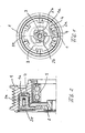
- Fig. 1 and 2 show a known type of a pulley 1, which has a drive plate 2 with a shaft 3 of a compressor, not shown, an air conditioner connected to a vehicle.
- Axial extensions 2a in the outer peripheral region of the drive plate 2 engage in recesses 1 a of the pulley 1, wherein rubber elements 4th between the extensions 2a of the drive plate 2 and the pulley 1 is arranged are, which absorb a relative movement between the drive plate 2 and pulley 1.
- 5 with a bearing in Fig. 2 denotes, by means of which the pulley 1 on the not shown housing of the compressor is rotatably mounted.
- the drive plate 2 has near the hub area predetermined breaking points 2b, which occurs when a specific Torque between the pulley 1 and shaft 3, for example, when blocking the Compressor, break and the connection between shaft 3 and pulley 1 permanently interrupt.
- the drive plate 2 is rigidly connected to the shaft 3 in this known design, for example, by screws in the hub region of the drive plate.
- a cap 6 the prevents leakage of sound waves.
- the volume of air above the drive plate 2 so limited that the oscillating drive plate 2 no larger Air volume can vibrate more. In this way, a very effective one becomes Noise emission to the outside prevented.
- the cap 6 may, as shown in FIG. 3, for example by means of a spring ring 7 on the Belt pulley 1 be attached.
- the cap itself may consist of plastic, wherein the edge region can be stiffened with a metal ring 6a. Even a cap off A plastic film significantly reduces the disturbing noise.
- Fig. 4 shows modified forms of attachment of the cap 6 on the pulley 1.
- Fig. 4a shows a metal ring 6'a with an approximately L-shaped cross-section through Screws 8 is connected to the pulley 1.
- Fig. 4b shows a latching connection between the pulley 1 and a locking lug 6b on the Scope of the cap 6, wherein the locking lug only on sections on the circumference can be provided.
- the detent engages in a groove 1b on the inner circumference of the pulley one.
- FIG. 4c shows a flange 6c of the covering cap which engages over the outer edge of the belt pulley 1, FIG. which engages in a groove on the outer circumference of the pulley 1.
- Fig. 4d shows a screw connection between the pulley 1 and cap 6, which with a circumferentially threaded annular body 6 d is connected to a thread on the inner circumference of the pulley 1 is engaged.
- the preferably made of plastic cap 6 preferably has a sound-insulating Construction.
- cavities in the cross-sectional view of the cap be provided, which act sound-absorbing.
- the cap 6 is formed closed. But it is also possible in the Area of the shaft 3 to provide an opening in the cap 6. This will be the Effectiveness of the cap is not affected, because the vibrations on the drive plate 2 occur in the outer peripheral region and lying in the waveband Air volume is hardly put into sound generating vibrations. Also, the distance the cap from the shaft circumference are kept low, so that prevented a sound leakage becomes.
- the attachment of a cap 6 on the pulley 1 is in particular also for it suitable to retrofit pulleys in the motor vehicle to the problem of noise to prevent.
- the cap 6 may also be attached to the shaft 3, with a small gap relative remains to the pulley 1.
- the cap is designed to be stiff, so that they can not be vibrated.
- a cap which is not even vibrated, can also on the drive plate be attached.
- the required air gap to the pulley is as possible small.
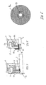
- Fig. 5 and 6 show schematically a second embodiment of the invention, wherein between Drive plate 2 and shaft 3, a relative movement in the axial direction is possible.
- the shaft 3 in the end a threaded portion 3a, on which a bushing 9 is screwed, which has a polygonal shape on the outer circumference has and with a complementarily shaped recess in the hub 2d of the drive plate 2 engages, so that in both directions torque from the pulley 1 can be transmitted to the shaft 3, the drive plate 2 but relatively in the axial direction to the shaft 3 can move.
- the previously described vibrations on the drive plate 2 by the axial mobility of the hub portion of the drive plate so attenuated that a noise is effectively prevented.
- the bushing 9 is a radially projecting flange 9a formed, the front side of the drive plate 2 via an axial mobility zuainsdes Damping element 9b can rest and contributes to vibration damping.
- the Socket 9 can also be held on the shaft via a circlip, not shown become.
- the end portion of the shaft 3 has a polygonal shape, with the drive plate 2 is engaged.
- Fig. 7 shows schematically a tongue and groove connection 10, 11 between the drive plate 2, which is held by a spring ring 3b on the shaft, and the shaft 3.
- the in a Recess on the shaft circumference inserted spring 10 is in an axial groove 11 of the hub the drive plate 2 slidably, so that in both directions of rotation torque can be transmitted, but a relative movement between the drive plate 2 and Shaft 3 in the axial direction is possible.
- the spring 10 so be designed to have a device for limiting the transmitted torque forms. For example, several distributed over the circumference of the shaft spring elements 10th be provided, the cross section of the predetermined breaking points 2b of the drive plate 2 in Fig. 1st correspond. As a result, such cross-sectional reductions 2b on the drive plate 2 itself omitted.
- the torque limiting device can also be integrated in the socket 9.
- Fig. 8 shows schematically the arrangement of a freewheel device 12 between shaft 3 and Mit Meetingcase 2, the only one direction of rotation, the transmission of torque from the pulley 1 allows the shaft 3 and in the opposite direction of rotation Run pulley 1 empty on the shaft 3. As a result, vibrations on the Drive plate 2 suppressed and thus a noise.
- the freewheel device 12 may be formed in a conventional manner, for example as Rollengesperre or similar.
- the described coupling between a pulley 1 and a shaft 3 by means of a vibratory drive plate 2 can not only with a compressor for air conditioning a motor vehicle, but are also used in other facilities, in which a vibratory drive plate between a drive element, here the pulley 1, and a driven element, here the shaft 3, used comes.
Abstract
Description
- Fig. 1
- eine Stirnansicht einer Mitnehmerscheibe an einer Riemenscheibe,
- Fig. 2
- einen Schnitt durch den Aufbau nach Fig. 1,
- Fig. 3
- schematisch die Anbringung einer Abdeckkappe nach einer ersten Ausführungsform,
- Fig. 4
- abgewandelte Bauformen der Befestigung der Abdeckkappe,
- Fig. 5
- eine Schnittansicht einer zweiten Ausführungsform,
- Fig. 6
- eine Stirnansicht der Buchse in Fig. 5,
- Fig. 7
- eine schematische Schnittdarstellung einer abgewandelten Bauform der zweiten Ausführungsform, und
- Fig. 8
- schematisch eine Schnittdarstellung einer dritten Ausführungsform.
Claims (11)
- Vorrichtung zur Übertragung eines Drehmoments von einer Riemenscheibe (1) auf eine Welle (3) unter Zwischenschaltung einer schwingungsfähigen Mitnehmerscheibe (2), insbesondere für den Antrieb eines Kompressors einer Klimaanlage bei einem Kraftfahrzeug,
dadurch gekennzeichnet, dass über der schwingungsfähigen Mitnehmerscheibe (2) eine Abdeckkappe (6) vorgesehen ist. - Vorrichtung nach Anspruch 1, wobei die Abdeckkappe (6) durch eine Schnapp- oder Schraubverbindung mit der Riemenscheibe (1) verbunden ist.
- Vorrichtung nach Anspruch 1 oder 2, wobei die Abdeckkappe (6) im Bereich der Welle (3) eine mittige Öffnung aufweist.
- Vorrichtung nach einem der Ansprüche 1 bis 3, wobei die Abdeckkappe (6) aus Kunststoff besteht.
- Vorrichtung nach einem der Ansprüche 1 bis 4, wobei die Abdeckkappe (6) einen schalldämmenden Aufbau hat.
- Vorrichtung zur Übertragung eines Drehmoments von einer Riemenscheibe (1) auf eine Welle (3) unter Zwischenschaltung einer schwingungsfähigen Mitnehmerscheibe (2), insbesondere für den Antrieb eines Kompressors einer Klimaanlage bei einem Kraftfahrzeug,
dadurch gekennzeichnet, dass die Mitnehmerscheibe (2) auf der Welle (3) in Achsrichtung verschiebbar geführt ist. - Vorrichtung nach Anspruch 6, wobei auf der Welle (3) eine Buchse (9) befestigt ist, die auf dem Außenumfang einen Polygonquerschnitt aufweist, der mit einer entsprechenden Polygon-Ausnehmung im Nabenbereich der Mitnehmerscheibe (2) in Eingriff steht.
- Vorrichtung nach Anspruch 6, wobei zwischen Mitnehmerscheibe (2) und Welle (3) eine Nut- und Federverbindung (10, 11) vorgesehen ist, die in Achsrichtung eine Relativbewegung zwischen Mitnehmerscheibe (2) und Welle (3) zulässt.
- Vorrichtung nach einem der Ansprüche 6 bis 8, wobei eine Drehmomentbegrenzungseinrichtung in die Schiebeführung der Mitnehmerscheibe (2) auf der Welle (3) bzw. in die Buchse (8) integriert ist.
- Vorrichtung zur Übertragung eines Drehmoments von einer Riemenscheibe (1) auf eine Welle (3) unter Zwischenschaltung einer schwingungsfähigen Mitnehmerscheibe (2), insbesondere für den Antrieb eines Kompressors einer Klimaanlage bei einem Kraftfahrzeug,
dadurch gekennzeichnet, dass zwischen Mitnehmerscheibe (2) und Welle (3) eine Freilaufeinrichtung (12) angeordnet ist, die eine Drehmomentübertragung nur in einer Drehrichtung zulässt. - Vorrichtung nach Anspruch 10, wobei in der Freilaufeinrichtung (12) eine Überlastsicherung bzw. eine Sollbruchstelle integriert ist.
Applications Claiming Priority (2)
| Application Number | Priority Date | Filing Date | Title |
|---|---|---|---|
| DE102004027688A DE102004027688A1 (de) | 2004-06-07 | 2004-06-07 | Vorrichtung zur Übertragung eines Drehmoments von einer Riemenscheibe auf eine Welle |
| DE102004027688 | 2004-06-07 |
Publications (2)
| Publication Number | Publication Date |
|---|---|
| EP1605189A2 true EP1605189A2 (de) | 2005-12-14 |
| EP1605189A3 EP1605189A3 (de) | 2009-04-01 |
Family
ID=34937296
Family Applications (1)
| Application Number | Title | Priority Date | Filing Date |
|---|---|---|---|
| EP05012262A Withdrawn EP1605189A3 (de) | 2004-06-07 | 2005-06-07 | Vorrichtung zur Übertragung eines Drehmoments von einer Riemenscheibe auf eine Welle |
Country Status (2)
| Country | Link |
|---|---|
| EP (1) | EP1605189A3 (de) |
| DE (1) | DE102004027688A1 (de) |
Cited By (3)
| Publication number | Priority date | Publication date | Assignee | Title |
|---|---|---|---|---|
| EP1801460A1 (de) * | 2005-12-21 | 2007-06-27 | LuK Lamellen und Kupplungsbau Beteiligungs KG | Antriebseinheit mit einem inneren Antriebselement und einem äusseren Antriebselement |
| FR2983527A1 (fr) * | 2011-12-05 | 2013-06-07 | Peugeot Citroen Automobiles Sa | Flasque d'isolation acoustique pour une poulie d'entrainement entrainee par un moteur a combustion interne, groupe motopropulseur et vehicule correspondants |
| FR2987648A1 (fr) * | 2012-03-05 | 2013-09-06 | Peugeot Citroen Automobiles Sa | Bouchon d'isolation acoustique pour poulie d'entrainement |
Families Citing this family (2)
| Publication number | Priority date | Publication date | Assignee | Title |
|---|---|---|---|---|
| US10066728B2 (en) | 2015-08-12 | 2018-09-04 | Deere & Company | Continuously variable transmission clutch sheave cover |
| DE102021126262B4 (de) | 2021-10-11 | 2024-01-25 | Schaeffler Technologies AG & Co. KG | Kupplungsvorrichtung mit einer Schraubverbindung |
Family Cites Families (10)
| Publication number | Priority date | Publication date | Assignee | Title |
|---|---|---|---|---|
| AT326956B (de) * | 1972-11-10 | 1976-01-12 | List Hans | Brennkraftmaschine mit schalldammend verkleideter keilriemenscheibe |
| GB2138097B (en) * | 1983-04-13 | 1986-09-10 | Ford Motor Co | Reduction of crankshaft noise from an internal combustion engine |
| DE4133286C1 (de) * | 1991-10-08 | 1993-01-07 | Fa. Carl Freudenberg, 6940 Weinheim, De | |
| DE19919449B4 (de) * | 1998-05-04 | 2015-10-15 | Schaeffler Technologies AG & Co. KG | Triebscheibe |
| US6588560B1 (en) * | 1999-11-19 | 2003-07-08 | Koyo Seiko Co., Ltd. | Pulley unit |
| JP4024979B2 (ja) * | 2000-02-18 | 2007-12-19 | カルソニックカンセイ株式会社 | 動力伝達装置 |
| JP2002139132A (ja) * | 2000-11-01 | 2002-05-17 | Denso Corp | プーリユニット |
| DE10102770A1 (de) * | 2001-01-23 | 2002-07-25 | Volkswagen Ag | Bauteil und Kapsel für Teile von Brennkraftmaschinen |
| US6722993B2 (en) * | 2001-03-15 | 2004-04-20 | Denso Corporation | Power transmission system |
| JP3915486B2 (ja) * | 2001-11-26 | 2007-05-16 | 株式会社デンソー | トルク伝達装置 |
-
2004
- 2004-06-07 DE DE102004027688A patent/DE102004027688A1/de not_active Withdrawn
-
2005
- 2005-06-07 EP EP05012262A patent/EP1605189A3/de not_active Withdrawn
Non-Patent Citations (1)
| Title |
|---|
| None |
Cited By (3)
| Publication number | Priority date | Publication date | Assignee | Title |
|---|---|---|---|---|
| EP1801460A1 (de) * | 2005-12-21 | 2007-06-27 | LuK Lamellen und Kupplungsbau Beteiligungs KG | Antriebseinheit mit einem inneren Antriebselement und einem äusseren Antriebselement |
| FR2983527A1 (fr) * | 2011-12-05 | 2013-06-07 | Peugeot Citroen Automobiles Sa | Flasque d'isolation acoustique pour une poulie d'entrainement entrainee par un moteur a combustion interne, groupe motopropulseur et vehicule correspondants |
| FR2987648A1 (fr) * | 2012-03-05 | 2013-09-06 | Peugeot Citroen Automobiles Sa | Bouchon d'isolation acoustique pour poulie d'entrainement |
Also Published As
| Publication number | Publication date |
|---|---|
| DE102004027688A1 (de) | 2006-01-05 |
| EP1605189A3 (de) | 2009-04-01 |
Similar Documents
| Publication | Publication Date | Title |
|---|---|---|
| DE102006028552B4 (de) | Kupplungseinrichtung mit Kupplungsscheibe | |
| EP1555449B1 (de) | Vorrichtung zur Übertragung eines Drehmomentes von einen Motor zu einem Kompressor | |
| EP2531686B1 (de) | Türmodul mit einem akustischen entkopplungsmittel | |
| EP1212824A1 (de) | Vorrichtung zur schwingungsisolierenden halterung eines elektromotors | |
| DE102012214214A1 (de) | Fliehkraftpendel auf Flansch | |
| DE2534684A1 (de) | Einrichtung zur schwingungsdaempfung im antriebsstrang von kraftfahrzeugen | |
| EP2240296A1 (de) | Handwerkzeugmaschine, insbesondere elektrisch betriebene handwerkzeugmaschine | |
| EP2951453B1 (de) | Elastische kupplung | |
| EP1605189A2 (de) | Vorrichtung zur Übertragung eines Drehmoments von einer Riemenscheibe auf eine Welle | |
| EP3118019A1 (de) | Freilaufnabe für ein fahrrad | |
| WO2014075660A2 (de) | Kraftfahrzeug-vakuumpumpe | |
| DE10161976A1 (de) | Befestigung einer Wischeranlage | |
| WO2019161840A1 (de) | Riemenscheibenentkoppler aufweisend eine fliehkraftpendeleinrichtung mit einer reibeinrichtung | |
| EP1488121A1 (de) | Vorrichtung zur kopplung einer gehauseanordnung einer kopplungseinrichtung mit einer rotoranordnung einer elektromaschine | |
| EP3427688B1 (de) | Zahnärztliches handstück | |
| EP1164305A2 (de) | Kupplungsglied | |
| DE4416449A1 (de) | Baueinheit aus einer Hydromaschine (Hydropumpe oder Hydromotor) und einem Träger | |
| DE102013217257A1 (de) | Hydraulikaggregat einer Fahrzeugbremsanlage mit einem Motorwellenlager | |
| EP1801460B1 (de) | Antriebseinheit mit einem inneren Antriebselement und einem äusseren Antriebselement | |
| DE102008041112A1 (de) | Radialbewegliches Loslager mit einstellbarer Anfederung | |
| EP0811781A2 (de) | Vorrichtung zum Dämpfen und Tilgen von Bremsgeräuschen | |
| DE19910813B4 (de) | Strömungsmaschinenrad | |
| EP1479909B1 (de) | Pleuel für den Kolben eines Verdichters | |
| DE202005017037U1 (de) | Ventilator | |
| WO2018060215A1 (de) | Verstelleinrichtung in einem kraftfahrzeug mit reibdämpfungssystem |
Legal Events
| Date | Code | Title | Description |
|---|---|---|---|
| PUAI | Public reference made under article 153(3) epc to a published international application that has entered the european phase |
Free format text: ORIGINAL CODE: 0009012 |
|
| AK | Designated contracting states |
Kind code of ref document: A2 Designated state(s): AT BE BG CH CY CZ DE DK EE ES FI FR GB GR HU IE IS IT LI LT LU MC NL PL PT RO SE SI SK TR |
|
| AX | Request for extension of the european patent |
Extension state: AL BA HR LV MK YU |
|
| PUAL | Search report despatched |
Free format text: ORIGINAL CODE: 0009013 |
|
| AK | Designated contracting states |
Kind code of ref document: A3 Designated state(s): AT BE BG CH CY CZ DE DK EE ES FI FR GB GR HU IE IS IT LI LT LU MC NL PL PT RO SE SI SK TR |
|
| AX | Request for extension of the european patent |
Extension state: AL BA HR LV MK YU |
|
| RIC1 | Information provided on ipc code assigned before grant |
Ipc: F16D 3/06 20060101ALI20090226BHEP Ipc: F16H 35/10 20060101ALI20090226BHEP Ipc: F16H 55/36 20060101AFI20051007BHEP |
|
| 17P | Request for examination filed |
Effective date: 20090929 |
|
| AKX | Designation fees paid |
Designated state(s): AT |
|
| REG | Reference to a national code |
Ref country code: DE Ref legal event code: 8566 |
|
| RBV | Designated contracting states (corrected) |
Designated state(s): DE |
|
| 17Q | First examination report despatched |
Effective date: 20120726 |
|
| STAA | Information on the status of an ep patent application or granted ep patent |
Free format text: STATUS: THE APPLICATION IS DEEMED TO BE WITHDRAWN |
|
| 18D | Application deemed to be withdrawn |
Effective date: 20150106 |