EP1605120A2 - Verriegelungsvorrichtung, insbesondere Zusatzverriegelungsvorrichtung, an einer Fahrgasttür eines Fahrzeugs des öffentlichen Personennah- oder -fernverkehrs - Google Patents
Verriegelungsvorrichtung, insbesondere Zusatzverriegelungsvorrichtung, an einer Fahrgasttür eines Fahrzeugs des öffentlichen Personennah- oder -fernverkehrs Download PDFInfo
- Publication number
- EP1605120A2 EP1605120A2 EP05011981A EP05011981A EP1605120A2 EP 1605120 A2 EP1605120 A2 EP 1605120A2 EP 05011981 A EP05011981 A EP 05011981A EP 05011981 A EP05011981 A EP 05011981A EP 1605120 A2 EP1605120 A2 EP 1605120A2
- Authority
- EP
- European Patent Office
- Prior art keywords
- locking device
- locking
- counter
- locking position
- force
- Prior art date
- Legal status (The legal status is an assumption and is not a legal conclusion. Google has not performed a legal analysis and makes no representation as to the accuracy of the status listed.)
- Granted
Links
- 230000001681 protective effect Effects 0.000 claims description 8
- 230000006835 compression Effects 0.000 description 2
- 238000007906 compression Methods 0.000 description 2
- 201000000251 Locked-in syndrome Diseases 0.000 description 1
- 230000007547 defect Effects 0.000 description 1
- 230000001419 dependent effect Effects 0.000 description 1
- 238000011161 development Methods 0.000 description 1
- 230000018109 developmental process Effects 0.000 description 1
- 238000006073 displacement reaction Methods 0.000 description 1
- 230000000694 effects Effects 0.000 description 1
- 238000011144 upstream manufacturing Methods 0.000 description 1
Images

Classifications
-
- E—FIXED CONSTRUCTIONS
- E05—LOCKS; KEYS; WINDOW OR DOOR FITTINGS; SAFES
- E05B—LOCKS; ACCESSORIES THEREFOR; HANDCUFFS
- E05B63/00—Locks or fastenings with special structural characteristics
- E05B63/24—Arrangements in which the fastening members which engage one another are mounted respectively on the wing and the frame and are both movable, e.g. for release by moving either of them
- E05B63/244—Arrangements in which the fastening members which engage one another are mounted respectively on the wing and the frame and are both movable, e.g. for release by moving either of them the striker being movable for latching, the bolt for unlatching, or vice versa
- E05B63/246—Emergency release from inside by releasing the striker
-
- E—FIXED CONSTRUCTIONS
- E05—LOCKS; KEYS; WINDOW OR DOOR FITTINGS; SAFES
- E05B—LOCKS; ACCESSORIES THEREFOR; HANDCUFFS
- E05B79/00—Mounting or connecting vehicle locks or parts thereof
- E05B79/10—Connections between movable lock parts
- E05B79/20—Connections between movable lock parts using flexible connections, e.g. Bowden cables
-
- E—FIXED CONSTRUCTIONS
- E05—LOCKS; KEYS; WINDOW OR DOOR FITTINGS; SAFES
- E05B—LOCKS; ACCESSORIES THEREFOR; HANDCUFFS
- E05B77/00—Vehicle locks characterised by special functions or purposes
Definitions
- the invention relates to a locking device, in particular an additional locking device, at a passenger door of a public vehicle Local or long-distance traffic with the characteristics from the generic term of claim 1
- the invention is based on the object, a locking device, in particular an additional locking device with the features of the Preamble of claim 1 in such a way that in an emergency unlocking is possible.
- the basic idea of the invention is the counter element, behind which the bolt engages, pivotally form, making it a lockable Locking position, in which a locking of the door is possible, can be pivoted into a release position in which released the latch is so that the door can be opened.
- This can be the pivoting of the counter element from the locking position into the release position take place against the force of a spring element under the action of the Counter element after release and moving away the bolt in the Locking position is returned.
- the lock for the counter element may comprise a displaceable holding element, which consists of a Locking position in which it is the pivoting movement of the counter element blocked, is displaceable in a Entarret istswolf in which it Swivel movement of the counter element releases.
- the displacement of the support member can be done against the force of another spring element, by which it is returned to the Arret istsrium.
- the movement of the Retaining element from the locking position in the Entarretier ein can of an emergency grip made via a Bowden cable.
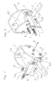
- an additional locking device is shown, the additional locking a passenger door, not shown, and a for example, on the door leaf, not shown, transversely to the opening direction of the
- sliding latch 1 which in the one shown in Fig. 1 locked state behind a counter-element 2 engages that within a Housing 5 is arranged, which in a manner not shown on the door portal can be arranged.
- the counter element 2 is pivotable about a pivot axis S in the housing 5 arranged. It has a locking surface 2.1, behind which locked in State of the latch 1 engages, and is shown in the in Figs. 1 to 3 Position against the force of a first spring element 3, as a leg spring is formed, in a shown in Fig. 4, downward release position pivotable, in which it can no longer hold the bolt 1 and this is released.
- the counter element 2 is in the locking position by a parallel to the pivot axis S of the counter element 2 displaceable Retaining element 4 lockable and not pivotable in the locking position.
- the support member 4 has three rollers 4.1, 4.2 and 4.3, the are arranged coaxially to each other and in the guides 5.1 on the housing.
- the rollers are 4.1 to 4.3 as a needle bearing educated. From the locking position shown in Fig. 1 is the support member 4 against the force of a second spring element 6 in a in Fig. 2nd and 3 shown Entarret istswolf slidably, in which it is the pivoting movement of the counter element 2 releases.
- the connection of the support element 4 with the housing 5 via a connecting rod 6.1, through the housing wall is guided, wherein the second spring element 6 on the outside the housing 5 is arranged, as for example from Figs. 2 and 3 to detect.
- the movement of the support member 4 can only hinted about Bowden cable 9 done that to an emergency handle, not shown leads.
- the effect of the second spring element 6, as a helical compression spring is formed, is that after loosening the Bowden cable 9, the support member 4 from the Entarret Sammlungswolf back into the Arretismeswolf is pushed back.
- a protective plate 7 In front of the front of his case facing the latch open housing 5 is a protective plate 7 slidably disposed under the force of a Helical compression spring formed third spring element 8 in a closed position is movable, in which it lies in the path of movement of the bolt 1, so that it can not be inserted into the counter element 2.
- the Guard plate 7 is by means of a guide member 7.1 on a guide rod 8.1 out, and the spring element 8 engages the guide element 7.1.
- At the bottom Area of the protective plate 7 is another guide in shape a slot 7.2, in which a fastened to the housing 5 bolt 7.3 engages.
- the function of the protective plate 7 is such that it occurs during the movement of the support element 4 taken in the locked position of this and against the force of the spring element 8 in a ⁇ ffnunswolf out of the way of the bolt 1 is moved. This has the consequence that in the locking position, in which the counter-element 2 is not pivotable, the latch 1 is inserted can be while in the Entarret réelleswolf, in which the counter element 2 is pivotable, due to the upstream protective plate 7 of Latch 1 can not be inserted.
- the Latch 1 is inserted into the counter element 2. This is possible because in the Normal state under the force of the second spring element 6, the support member 4 is located in the locking position and the counter element. 2 is not pivotable and the protective plate 7 releases the way of the bolt 1.
Landscapes
- Physics & Mathematics (AREA)
- Electromagnetism (AREA)
- Engineering & Computer Science (AREA)
- Structural Engineering (AREA)
- Lock And Its Accessories (AREA)
Abstract
Description
- Fig. 1
- in einer perspektivischen Darstellung eine Verriegelungsvorrichtung im verriegelten Zustand;
- Fig. 2
- in einer perspektivischen Darstellung aus anderem Blickwinkel die Verriegelungsvorrichtung nach Fig. 1 im verriegelten Zustand bei entarretiertem Gegenelement;
- Fig. 3
- in einer perspektivischen Darstellung in das Innere des Gehäuses der Vorrichtung nach Fig. 1 und 2 im Zustand gemäß Fig. 2;
- Fig. 4
- die Vorrichtung nach Fig. 1 bis 3 im entarretierten und abgeschwenkten Zustand des Gegenelements;
- Fig. 5
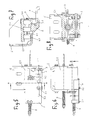
- die Verriegelungsvorrichtung nach Fig. 1 bis 4 in einer Ansicht von vorne;
- Fig. 6
- die Verriegelungsvorrichtung nach Fig. 1 bis 4 in einer Ansicht von oben;
- Fig. 7
- einen Schnitt nach der Linie A-A in Fig. 5;
- Fig. 8
- einen Schnitt nach der Linie B-B in Fig. 6.
Claims (8)
- Verriegelungsvorrichtung, insbesondere Zusatzverriegelungsvorrichtung, an einer Fahrgasttür eines Fahrzeugs des öffentlichen Personennah- oder -fernverkehrs, mit einem am Türblatt oder Türportal angeordneten, quer zur Öffnungsrichtung des Türblatts verschiebbaren Riegel, der im verriegelten Zustand hinter ein am Türportal oder am Türblatt angeordnetes Gegenelement greift, dadurch gekennzeichnet, dass das Gegenelement (2) schwenkbar ausgebildet und aus einer arretierbaren Verriegelungsstellung, in der es mit einer Verriegelungsfläche (2.1) den hintergreifenden Riegel (1) festhält, nach Lösen der Arretierung in eine Freigabestellung verschwenkbar ist, in welcher es den Riegel (1) freigibt.
- Verriegelungsvorrichtung nach Anspruch 1, dadurch gekennzeichnet, dass die Verschwenkung des Gegenelements (2) aus der Verriegelungsstellung in die Freigabestellung gegen die Kraft eines ersten Federelements (3) erfolgt, unter dessen Einwirkung das Gegenelement (2) nach der Freigabe und der Wegbewegung des Riegels (1) in die Verriegelungsstellung zurückgeführt wird.
- Verriegelungsvorrichtung nach Anspruch 1 oder 2, dadurch gekennzeichnet, dass die Arretierung für das Gegenelement (2) ein parallel zur Schwenkachse (S) des Gegenelements (2) verschiebbares Halterungselement (4) aufweist, das sich an einem festen Gehäuse (5) abstützt und aus einer Arretierungsstellung, in der es an einer der Schwenkbewegung folgenden Oberfläche (2.2) des Gegenelements (2) anliegt, gegen die Kraft eines zweiten Federelements (6) in eine Entarretierungsstellung verschiebbar ist, in der es die Schwenkbewegung des Gegenelements (2) freigibt.
- Verriegelungsvorrichtung nach Anspruch 3, dadurch gekennzeichnet, dass das Halterungselement (4) mindestens eine Rolle (4.1 bis 4.3) aufweist, die in Führungen (5.1) des Gehäuses (5) läuft und gegen die Kraft des zweiten Federelements (6) aus der Arretierstellung in die Entarretierstellung verschiebbar ist.
- Verriegelungsvorrichtung nach Anspruch 4, dadurch gekennzeichnet, dass das Halterungselement (4) drei koaxial zueinander angeordnete Rollen (4.1 bis 4.3) aufweist, von denen zwei Rollen (4.1, 4.2) am Gehäuse (5) geführt sind und die dritte Rolle (4.3) in der Arretierstellung an der der Schwenkbewegung folgenden Oberfläche (2.2) des Gegenelements (2) anliegt.
- Verriegelungsvorrichtung nach Anspruch 5, dadurch gekennzeichnet, dass die Rollen (4.1 bis 4.3) als Nadellager ausgebildet sind.
- Verriegelungsvorrichtung nach einem der Ansprüche 3 bis 6, gekennzeichnet durch eine Schutzplatte (7), die unter der Kraft eines dritten Federelements (8) in eine Verschlusstellung bewegbar ist, in der sie eine Verriegelung des Türblatts verhindernd im Weg des Riegels (1) liegt, und die bei der Bewegung des Halterungselements (4) in die Arretierstellung von diesem mitgenommen und gegen die Kraft des dritten Federelements (8) in eine Öffnungsstellung außerhalb des Weges des Riegels (1) bewegt wird.
- Verriegelungsvorrichtung nach einem der Ansprüche 3 bis 7, dadurch gekennzeichnet, dass die Bewegung des Halterungselements (4) aus der Arretierungsstellung in die Entarretierungsstellung über einen Bowdenzug (9) erfolgt.
Priority Applications (1)
| Application Number | Priority Date | Filing Date | Title |
|---|---|---|---|
| PL05011981T PL1605120T3 (pl) | 2004-06-08 | 2005-06-03 | Urządzenie ryglujące, w szczególności dodatkowe urządzenie ryglujące, w drzwiach dla pasażerów w pojeździe komunikacji publicznej bliskiego albo dalekiego zasięgu |
Applications Claiming Priority (2)
| Application Number | Priority Date | Filing Date | Title |
|---|---|---|---|
| DE202004009077U DE202004009077U1 (de) | 2004-06-08 | 2004-06-08 | Verriegelungsvorrichtung, insbesondere Zusatzverriegelungsvorrichtung, an einer Fahrgasttür eines Fahrzeugs des öffentlichen Personennah- oder -fernverkehrs |
| DE202004009077U | 2004-06-08 |
Publications (3)
| Publication Number | Publication Date |
|---|---|
| EP1605120A2 true EP1605120A2 (de) | 2005-12-14 |
| EP1605120A3 EP1605120A3 (de) | 2008-05-21 |
| EP1605120B1 EP1605120B1 (de) | 2013-02-20 |
Family
ID=32946700
Family Applications (1)
| Application Number | Title | Priority Date | Filing Date |
|---|---|---|---|
| EP05011981A Expired - Lifetime EP1605120B1 (de) | 2004-06-08 | 2005-06-03 | Verriegelungsvorrichtung, insbesondere Zusatzverriegelungsvorrichtung, an einer Fahrgasttür eines Fahrzeugs des öffentlichen Personennah- oder -fernverkehrs |
Country Status (4)
| Country | Link |
|---|---|
| EP (1) | EP1605120B1 (de) |
| DE (1) | DE202004009077U1 (de) |
| ES (1) | ES2405271T3 (de) |
| PL (1) | PL1605120T3 (de) |
Citations (3)
| Publication number | Priority date | Publication date | Assignee | Title |
|---|---|---|---|---|
| US2762645A (en) | 1953-12-23 | 1956-09-11 | Jr Lawrence M Bordner | Keeper |
| GB2275733A (en) | 1993-03-01 | 1994-09-07 | Takigen Mfg Co | Door handle assembly with releasable keep |
| DE29821524U1 (de) | 1998-12-02 | 1999-03-11 | Bks Gmbh, 42549 Velbert | Mechanisch übersteuerter Türöffner |
Family Cites Families (1)
| Publication number | Priority date | Publication date | Assignee | Title |
|---|---|---|---|---|
| DE4105545C1 (de) * | 1991-02-22 | 1992-06-17 | Mercedes-Benz Aktiengesellschaft, 7000 Stuttgart, De |
-
2004
- 2004-06-08 DE DE202004009077U patent/DE202004009077U1/de not_active Expired - Lifetime
-
2005
- 2005-06-03 ES ES05011981T patent/ES2405271T3/es not_active Expired - Lifetime
- 2005-06-03 EP EP05011981A patent/EP1605120B1/de not_active Expired - Lifetime
- 2005-06-03 PL PL05011981T patent/PL1605120T3/pl unknown
Patent Citations (3)
| Publication number | Priority date | Publication date | Assignee | Title |
|---|---|---|---|---|
| US2762645A (en) | 1953-12-23 | 1956-09-11 | Jr Lawrence M Bordner | Keeper |
| GB2275733A (en) | 1993-03-01 | 1994-09-07 | Takigen Mfg Co | Door handle assembly with releasable keep |
| DE29821524U1 (de) | 1998-12-02 | 1999-03-11 | Bks Gmbh, 42549 Velbert | Mechanisch übersteuerter Türöffner |
Also Published As
| Publication number | Publication date |
|---|---|
| ES2405271T3 (es) | 2013-05-30 |
| EP1605120A3 (de) | 2008-05-21 |
| DE202004009077U1 (de) | 2004-09-02 |
| PL1605120T3 (pl) | 2013-08-30 |
| EP1605120B1 (de) | 2013-02-20 |
Similar Documents
| Publication | Publication Date | Title |
|---|---|---|
| DE19517526A1 (de) | Mehrfachverriegelungsanordnung | |
| EP2133494B1 (de) | Sicherheitsverriegelungsvorrichtung mit Fluchtentriegelungseinrichtung | |
| DE2433322B2 (de) | Panik-Hauptschloß mit Fallen-Nebenverschlüssen | |
| WO2022078840A1 (de) | Schiebetür | |
| EP1325995B1 (de) | Auszugsicherung, insbesondere für einen Schubladenschrank | |
| DE102015211980B4 (de) | Verschlussvorrichtung für ein ein- oder mehrteiliges Tor | |
| EP3243985B1 (de) | Schloss für einen schwenkbaren flügel | |
| DE1653995A1 (de) | Sicherheitseinrichtung | |
| DE202007016091U1 (de) | Treibstangenschloss | |
| EP1605120B1 (de) | Verriegelungsvorrichtung, insbesondere Zusatzverriegelungsvorrichtung, an einer Fahrgasttür eines Fahrzeugs des öffentlichen Personennah- oder -fernverkehrs | |
| DE2518318A1 (de) | Verriegelungsvorrichtung | |
| DE102018115985A1 (de) | Schlossgegenkasten für ein Aktivflügelschloss mit Falzluftausgleich | |
| EP0538419B1 (de) | Schliesssystem | |
| DE10151870A1 (de) | Vorrichtung zur Betätigung eines Verschlusses von Türen oder Klappen, insbesondere an Fahrzeugen | |
| DE1919347A1 (de) | Automatische Verriegelung | |
| DE19700706B4 (de) | Vorrichtung zum Verriegeln einer Klappe einer Rückenlehne eines Kraftfahrzeugrücksitzes | |
| EP1024240B1 (de) | Verriegelungsvorrichtung | |
| DE19906232B4 (de) | Vorrichtung zum Ver- und Entriegeln eines Standflügels | |
| DE102023105087B3 (de) | Möbelauszug, insbesondere für einen Hochschrank, mit einer Sicherungseinrichtung | |
| DE9403399U1 (de) | Fenster- oder Türsicherung | |
| DE60106847T2 (de) | Verriegelungseinheit für eine Platte zum Verschliessen eines Zugangs zu einer unterirdischen Kammer | |
| DE10202528A1 (de) | Mechanische Verriegelung für eine Fahrkorbschiebetür | |
| DE2920005A1 (de) | Schrank mit mindestens zwei schiebetueren | |
| DE102021113922A1 (de) | Verschlusssystem für ein Möbel | |
| EP0189814A2 (de) | Vorrichtung zum Feststellen eines geöffneten Fenster- oder Türladens |
Legal Events
| Date | Code | Title | Description |
|---|---|---|---|
| PUAI | Public reference made under article 153(3) epc to a published international application that has entered the european phase |
Free format text: ORIGINAL CODE: 0009012 |
|
| AK | Designated contracting states |
Kind code of ref document: A2 Designated state(s): AT BE BG CH CY CZ DE DK EE ES FI FR GB GR HU IE IS IT LI LT LU MC NL PL PT RO SE SI SK TR |
|
| AX | Request for extension of the european patent |
Extension state: AL BA HR LV MK YU |
|
| PUAL | Search report despatched |
Free format text: ORIGINAL CODE: 0009013 |
|
| AK | Designated contracting states |
Kind code of ref document: A3 Designated state(s): AT BE BG CH CY CZ DE DK EE ES FI FR GB GR HU IE IS IT LI LT LU MC NL PL PT RO SE SI SK TR |
|
| AX | Request for extension of the european patent |
Extension state: AL BA HR LV MK YU |
|
| 17P | Request for examination filed |
Effective date: 20081121 |
|
| AKX | Designation fees paid |
Designated state(s): AT BE BG CH CY CZ DE DK EE ES FI FR GB GR HU IE IS IT LI LT LU MC NL PL PT RO SE SI SK TR |
|
| 17Q | First examination report despatched |
Effective date: 20100610 |
|
| GRAP | Despatch of communication of intention to grant a patent |
Free format text: ORIGINAL CODE: EPIDOSNIGR1 |
|
| GRAS | Grant fee paid |
Free format text: ORIGINAL CODE: EPIDOSNIGR3 |
|
| GRAA | (expected) grant |
Free format text: ORIGINAL CODE: 0009210 |
|
| AK | Designated contracting states |
Kind code of ref document: B1 Designated state(s): AT BE BG CH CY CZ DE DK EE ES FI FR GB GR HU IE IS IT LI LT LU MC NL PL PT RO SE SI SK TR |
|
| REG | Reference to a national code |
Ref country code: GB Ref legal event code: FG4D Free format text: NOT ENGLISH |
|
| REG | Reference to a national code |
Ref country code: CH Ref legal event code: EP |
|
| REG | Reference to a national code |
Ref country code: AT Ref legal event code: REF Ref document number: 597653 Country of ref document: AT Kind code of ref document: T Effective date: 20130315 |
|
| REG | Reference to a national code |
Ref country code: IE Ref legal event code: FG4D Free format text: LANGUAGE OF EP DOCUMENT: GERMAN |
|
| REG | Reference to a national code |
Ref country code: DE Ref legal event code: R096 Ref document number: 502005013472 Country of ref document: DE Effective date: 20130418 |
|
| REG | Reference to a national code |
Ref country code: ES Ref legal event code: FG2A Ref document number: 2405271 Country of ref document: ES Kind code of ref document: T3 Effective date: 20130530 |
|
| REG | Reference to a national code |
Ref country code: NL Ref legal event code: T3 |
|
| REG | Reference to a national code |
Ref country code: LT Ref legal event code: MG4D |
|
| PG25 | Lapsed in a contracting state [announced via postgrant information from national office to epo] |
Ref country code: IS Free format text: LAPSE BECAUSE OF FAILURE TO SUBMIT A TRANSLATION OF THE DESCRIPTION OR TO PAY THE FEE WITHIN THE PRESCRIBED TIME-LIMIT Effective date: 20130620 Ref country code: LT Free format text: LAPSE BECAUSE OF FAILURE TO SUBMIT A TRANSLATION OF THE DESCRIPTION OR TO PAY THE FEE WITHIN THE PRESCRIBED TIME-LIMIT Effective date: 20130220 Ref country code: SE Free format text: LAPSE BECAUSE OF FAILURE TO SUBMIT A TRANSLATION OF THE DESCRIPTION OR TO PAY THE FEE WITHIN THE PRESCRIBED TIME-LIMIT Effective date: 20130220 Ref country code: BG Free format text: LAPSE BECAUSE OF FAILURE TO SUBMIT A TRANSLATION OF THE DESCRIPTION OR TO PAY THE FEE WITHIN THE PRESCRIBED TIME-LIMIT Effective date: 20130520 |
|
| PG25 | Lapsed in a contracting state [announced via postgrant information from national office to epo] |
Ref country code: GR Free format text: LAPSE BECAUSE OF FAILURE TO SUBMIT A TRANSLATION OF THE DESCRIPTION OR TO PAY THE FEE WITHIN THE PRESCRIBED TIME-LIMIT Effective date: 20130521 Ref country code: FI Free format text: LAPSE BECAUSE OF FAILURE TO SUBMIT A TRANSLATION OF THE DESCRIPTION OR TO PAY THE FEE WITHIN THE PRESCRIBED TIME-LIMIT Effective date: 20130220 Ref country code: SI Free format text: LAPSE BECAUSE OF FAILURE TO SUBMIT A TRANSLATION OF THE DESCRIPTION OR TO PAY THE FEE WITHIN THE PRESCRIBED TIME-LIMIT Effective date: 20130220 Ref country code: PT Free format text: LAPSE BECAUSE OF FAILURE TO SUBMIT A TRANSLATION OF THE DESCRIPTION OR TO PAY THE FEE WITHIN THE PRESCRIBED TIME-LIMIT Effective date: 20130620 |
|
| REG | Reference to a national code |
Ref country code: PL Ref legal event code: T3 |
|
| PG25 | Lapsed in a contracting state [announced via postgrant information from national office to epo] |
Ref country code: SK Free format text: LAPSE BECAUSE OF FAILURE TO SUBMIT A TRANSLATION OF THE DESCRIPTION OR TO PAY THE FEE WITHIN THE PRESCRIBED TIME-LIMIT Effective date: 20130220 Ref country code: RO Free format text: LAPSE BECAUSE OF FAILURE TO SUBMIT A TRANSLATION OF THE DESCRIPTION OR TO PAY THE FEE WITHIN THE PRESCRIBED TIME-LIMIT Effective date: 20130220 Ref country code: EE Free format text: LAPSE BECAUSE OF FAILURE TO SUBMIT A TRANSLATION OF THE DESCRIPTION OR TO PAY THE FEE WITHIN THE PRESCRIBED TIME-LIMIT Effective date: 20130220 Ref country code: DK Free format text: LAPSE BECAUSE OF FAILURE TO SUBMIT A TRANSLATION OF THE DESCRIPTION OR TO PAY THE FEE WITHIN THE PRESCRIBED TIME-LIMIT Effective date: 20130220 |
|
| PG25 | Lapsed in a contracting state [announced via postgrant information from national office to epo] |
Ref country code: CY Free format text: LAPSE BECAUSE OF FAILURE TO SUBMIT A TRANSLATION OF THE DESCRIPTION OR TO PAY THE FEE WITHIN THE PRESCRIBED TIME-LIMIT Effective date: 20130220 |
|
| PLBE | No opposition filed within time limit |
Free format text: ORIGINAL CODE: 0009261 |
|
| STAA | Information on the status of an ep patent application or granted ep patent |
Free format text: STATUS: NO OPPOSITION FILED WITHIN TIME LIMIT |
|
| BERE | Be: lapsed |
Owner name: GEBR. BODE G.M.B.H. & CO. KG Effective date: 20130630 |
|
| 26N | No opposition filed |
Effective date: 20131121 |
|
| PG25 | Lapsed in a contracting state [announced via postgrant information from national office to epo] |
Ref country code: MC Free format text: LAPSE BECAUSE OF FAILURE TO SUBMIT A TRANSLATION OF THE DESCRIPTION OR TO PAY THE FEE WITHIN THE PRESCRIBED TIME-LIMIT Effective date: 20130220 |
|
| REG | Reference to a national code |
Ref country code: DE Ref legal event code: R097 Ref document number: 502005013472 Country of ref document: DE Effective date: 20131121 |
|
| REG | Reference to a national code |
Ref country code: IE Ref legal event code: MM4A |
|
| PG25 | Lapsed in a contracting state [announced via postgrant information from national office to epo] |
Ref country code: BE Free format text: LAPSE BECAUSE OF NON-PAYMENT OF DUE FEES Effective date: 20130630 |
|
| PG25 | Lapsed in a contracting state [announced via postgrant information from national office to epo] |
Ref country code: IE Free format text: LAPSE BECAUSE OF NON-PAYMENT OF DUE FEES Effective date: 20130603 |
|
| PG25 | Lapsed in a contracting state [announced via postgrant information from national office to epo] |
Ref country code: HU Free format text: LAPSE BECAUSE OF FAILURE TO SUBMIT A TRANSLATION OF THE DESCRIPTION OR TO PAY THE FEE WITHIN THE PRESCRIBED TIME-LIMIT; INVALID AB INITIO Effective date: 20050603 Ref country code: LU Free format text: LAPSE BECAUSE OF NON-PAYMENT OF DUE FEES Effective date: 20130603 |
|
| REG | Reference to a national code |
Ref country code: FR Ref legal event code: PLFP Year of fee payment: 12 |
|
| REG | Reference to a national code |
Ref country code: FR Ref legal event code: PLFP Year of fee payment: 13 |
|
| REG | Reference to a national code |
Ref country code: FR Ref legal event code: PLFP Year of fee payment: 14 |
|
| PGFP | Annual fee paid to national office [announced via postgrant information from national office to epo] |
Ref country code: CZ Payment date: 20190524 Year of fee payment: 15 Ref country code: IT Payment date: 20190619 Year of fee payment: 15 Ref country code: NL Payment date: 20190619 Year of fee payment: 15 Ref country code: PL Payment date: 20190521 Year of fee payment: 15 |
|
| PGFP | Annual fee paid to national office [announced via postgrant information from national office to epo] |
Ref country code: TR Payment date: 20190527 Year of fee payment: 15 Ref country code: FR Payment date: 20190625 Year of fee payment: 15 |
|
| PGFP | Annual fee paid to national office [announced via postgrant information from national office to epo] |
Ref country code: CH Payment date: 20190624 Year of fee payment: 15 |
|
| PGFP | Annual fee paid to national office [announced via postgrant information from national office to epo] |
Ref country code: NO Payment date: 20190325 Year of fee payment: 4 Ref country code: AT Payment date: 20190618 Year of fee payment: 15 |
|
| PG25 | Lapsed in a contracting state [announced via postgrant information from national office to epo] |
Ref country code: CZ Free format text: LAPSE BECAUSE OF NON-PAYMENT OF DUE FEES Effective date: 20200603 |
|
| REG | Reference to a national code |
Ref country code: CH Ref legal event code: PL |
|
| REG | Reference to a national code |
Ref country code: NL Ref legal event code: MM Effective date: 20200701 |
|
| REG | Reference to a national code |
Ref country code: AT Ref legal event code: MM01 Ref document number: 597653 Country of ref document: AT Kind code of ref document: T Effective date: 20200603 |
|
| PG25 | Lapsed in a contracting state [announced via postgrant information from national office to epo] |
Ref country code: FR Free format text: LAPSE BECAUSE OF NON-PAYMENT OF DUE FEES Effective date: 20200630 Ref country code: NL Free format text: LAPSE BECAUSE OF NON-PAYMENT OF DUE FEES Effective date: 20200701 Ref country code: CH Free format text: LAPSE BECAUSE OF NON-PAYMENT OF DUE FEES Effective date: 20200630 Ref country code: LI Free format text: LAPSE BECAUSE OF NON-PAYMENT OF DUE FEES Effective date: 20200630 |
|
| PG25 | Lapsed in a contracting state [announced via postgrant information from national office to epo] |
Ref country code: AT Free format text: LAPSE BECAUSE OF NON-PAYMENT OF DUE FEES Effective date: 20200603 |
|
| PGFP | Annual fee paid to national office [announced via postgrant information from national office to epo] |
Ref country code: DE Payment date: 20210621 Year of fee payment: 17 |
|
| PGFP | Annual fee paid to national office [announced via postgrant information from national office to epo] |
Ref country code: GB Payment date: 20210623 Year of fee payment: 17 |
|
| REG | Reference to a national code |
Ref country code: ES Ref legal event code: FD2A Effective date: 20211026 |
|
| PG25 | Lapsed in a contracting state [announced via postgrant information from national office to epo] |
Ref country code: ES Free format text: LAPSE BECAUSE OF NON-PAYMENT OF DUE FEES Effective date: 20200604 |
|
| REG | Reference to a national code |
Ref country code: DE Ref legal event code: R081 Ref document number: 502005013472 Country of ref document: DE Owner name: BODE - DIE TUER GMBH, DE Free format text: FORMER OWNER: GEBR. BODE GMBH & CO. KG, 34123 KASSEL, DE |
|
| PG25 | Lapsed in a contracting state [announced via postgrant information from national office to epo] |
Ref country code: IT Free format text: LAPSE BECAUSE OF NON-PAYMENT OF DUE FEES Effective date: 20200603 |
|
| PG25 | Lapsed in a contracting state [announced via postgrant information from national office to epo] |
Ref country code: TR Free format text: LAPSE BECAUSE OF NON-PAYMENT OF DUE FEES Effective date: 20200603 |
|
| PG25 | Lapsed in a contracting state [announced via postgrant information from national office to epo] |
Ref country code: PL Free format text: LAPSE BECAUSE OF NON-PAYMENT OF DUE FEES Effective date: 20200603 |
|
| REG | Reference to a national code |
Ref country code: DE Ref legal event code: R119 Ref document number: 502005013472 Country of ref document: DE |
|
| GBPC | Gb: european patent ceased through non-payment of renewal fee |
Effective date: 20220603 |
|
| PG25 | Lapsed in a contracting state [announced via postgrant information from national office to epo] |
Ref country code: GB Free format text: LAPSE BECAUSE OF NON-PAYMENT OF DUE FEES Effective date: 20220603 Ref country code: DE Free format text: LAPSE BECAUSE OF NON-PAYMENT OF DUE FEES Effective date: 20230103 |