EP1604562A1 - Landwirtschaftliches Transportfahrzeug - Google Patents
Landwirtschaftliches Transportfahrzeug Download PDFInfo
- Publication number
- EP1604562A1 EP1604562A1 EP05012279A EP05012279A EP1604562A1 EP 1604562 A1 EP1604562 A1 EP 1604562A1 EP 05012279 A EP05012279 A EP 05012279A EP 05012279 A EP05012279 A EP 05012279A EP 1604562 A1 EP1604562 A1 EP 1604562A1
- Authority
- EP
- European Patent Office
- Prior art keywords
- transport vehicle
- drive
- agricultural
- vehicle according
- agricultural transport
- Prior art date
- Legal status (The legal status is an assumption and is not a legal conclusion. Google has not performed a legal analysis and makes no representation as to the accuracy of the status listed.)
- Granted
Links
- 210000003608 fece Anatomy 0.000 claims abstract description 5
- 230000005540 biological transmission Effects 0.000 claims abstract description 4
- 239000010871 livestock manure Substances 0.000 claims abstract description 4
- 244000025254 Cannabis sativa Species 0.000 claims abstract description 3
- 239000010902 straw Substances 0.000 claims abstract description 3
- 238000007599 discharging Methods 0.000 claims 2
- 241000196324 Embryophyta Species 0.000 abstract 1
- 230000008901 benefit Effects 0.000 description 4
- 238000009434 installation Methods 0.000 description 2
- 230000002411 adverse Effects 0.000 description 1
- 238000013459 approach Methods 0.000 description 1
- 230000000712 assembly Effects 0.000 description 1
- 238000000429 assembly Methods 0.000 description 1
- 230000002146 bilateral effect Effects 0.000 description 1
- 238000010276 construction Methods 0.000 description 1
- 230000001419 dependent effect Effects 0.000 description 1
- 230000000694 effects Effects 0.000 description 1
- 238000005516 engineering process Methods 0.000 description 1
- 238000000605 extraction Methods 0.000 description 1
- 239000004463 hay Substances 0.000 description 1
- 238000000034 method Methods 0.000 description 1
Images

Classifications
-
- B—PERFORMING OPERATIONS; TRANSPORTING
- B60—VEHICLES IN GENERAL
- B60P—VEHICLES ADAPTED FOR LOAD TRANSPORTATION OR TO TRANSPORT, TO CARRY, OR TO COMPRISE SPECIAL LOADS OR OBJECTS
- B60P1/00—Vehicles predominantly for transporting loads and modified to facilitate loading, consolidating the load, or unloading
- B60P1/36—Vehicles predominantly for transporting loads and modified to facilitate loading, consolidating the load, or unloading using endless chains or belts thereon
- B60P1/38—Vehicles predominantly for transporting loads and modified to facilitate loading, consolidating the load, or unloading using endless chains or belts thereon forming the main load-transporting element or part thereof
-
- A—HUMAN NECESSITIES
- A01—AGRICULTURE; FORESTRY; ANIMAL HUSBANDRY; HUNTING; TRAPPING; FISHING
- A01C—PLANTING; SOWING; FERTILISING
- A01C3/00—Treating manure; Manuring
- A01C3/06—Manure distributors, e.g. dung distributors
-
- A—HUMAN NECESSITIES
- A01—AGRICULTURE; FORESTRY; ANIMAL HUSBANDRY; HUNTING; TRAPPING; FISHING
- A01D—HARVESTING; MOWING
- A01D90/00—Vehicles for carrying harvested crops with means for selfloading or unloading
- A01D90/14—Adaptations of gearing for driving, loading or unloading means
Definitions
- the invention relates to an agricultural transport vehicle for transporting and Unloading of grass, hay, straw, manure or similar agricultural cargo, with a drivable scraper floor for conveying and unloading the cargo.
- Such agricultural transport vehicles with a scraper floor are in practice in various versions known. So it can be both a well-known Manure spreader act, or even a loader wagon with various other functional assemblies such as picking and cutting devices for picking up crops which lies on the ground and subsequent cutting of the crop during the extraction into the hold or dosing devices for a smooth, loosened discharge of the crop. It can also be a simple transport cart for crops act, which are also known as Hburgselwagen. All named agricultural Transport vehicles in common, however, is a so-called scraper floor. A scraper floor is one Arrangement with chain wheels guided by endless chains, with the help of cross bars of Pulled backwards over the floor of the vehicle's cargo compartment. How to transport these cross bars z. B. the recorded at the front end of the loading wagon crop both during loading as well as during unloading in the loading area from the front to the rear opening of the cargo space.
- Preferred state of the art in the drives of the scraper floors are hydraulic motors via an intermediate gear arranged at the rear end of the bed drive and Drive the deflection shaft of the floor conveyor from outside the frame.
- different drive speeds are either multi-stage motors used or made stepless regulations on the quantities of oil.
- the externally arranged on the frame of the vehicles drives adversely affect on the vehicle width.
- By outwardly projecting drives is the usable Width of the cargo bed limited by compliance with the maximum permissible outside dimensions.
- the drives in this position are extremely vulnerable and vulnerable to damage.
- the present invention is therefore an object of an improved agricultural To provide transport vehicle, which avoids the disadvantages of the prior art and it thereby advantageously develops.
- an improved scraper floor drive be created at a reduced cost and less installation effort.
- the scraper floor drive in the context of Laying the cargo area of the transport vehicle, whereby the drive for a particularly protected
- the loading area width is not affected since it is not the broadest determining factor Component is.
- This space-saving arrangement of the drive which also with double-sided drive is possible, is inventively made possible by the fact that the drive assembly in the Art a flying storage at the end of the scraper floor drive shaft is plugged in and thereby at the same time takes over the function of the support bearing of the scraper floor drive shaft.
- For bilateral Drive are thus the drives directly through the scraper floor drive shaft with each other connected.
- the scraper floor drive shaft is the transmission output shaft of both Drives and the gearbox output bearings are also the support bearings of the scraper floor drive shaft.
- the drive in the Side members of the vehicle frame exclusively by positive shots and Recesses recorded and secured against rotation. So is a montage of the whole Scraper floor drive without tools and without the use of securing elements such as screws, Bolt etc. possible. Only the hydraulic connection of the drive motors must still done. In its position the whole drive is held by the tension of the subsequently mounted scraper floor chains. Due to this advantageous simple assembly unnecessary An alignment of the components and tension by different operating conditions can not even occur due to the freedom of movement of the drives.
- Fig. 1 shows a loader wagon 1 as an embodiment of an agricultural transport vehicle with a drive assembly 2 according to the invention for the scraper floor 3.
- Der partially self-propelled loading wagons is with a receiving and delivery unit 4 equipped with the particular halm- or leaf-shaped crop, which, as a rule previously gathered into swathes, taken up on the field floor and the Loading space 5 is supplied.
- the crop is driven by the Floor conveyor 3 so promoted backwards in the direction of the discharge opening 6 that a optimal filling of the cargo space 5 is given.
- the loader wagon 1 of the embodiment has at the rear end of the loading space 5 a Dosing 7 on.
- the rotatably driven rollers 8 detect the metering device 7, the load, which by the simultaneously driven scraper floor 3 is supplied to it and is discharged so loose and evenly distributed.
- the discharge opening 6 is outside the Unloading closed with a not shown upwardly pivotable tailgate.
- the drive assembly 2 of the floor conveyor 3 is preferably at the rear end of the loading space. 5 arranged so that the load in its main transport direction of the drawn Lasttrum of the Kratz convinceds 3 is transported.
- the invisible front deflection of the scraper floor 3 is used at the same time as a clamping device.
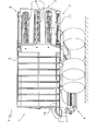
- the detail of the scraper floor drive assembly 2 of Fig. 2 clearly shows the simple construction and installation of this module.
- a split one Scraper floor shown.
- Each two Kratzteilketten 9 are over the entire length with in equipped with a certain measure spaced scraper floor strips 10 and thus form a Floor conveyor half. Since both scraper floor halves, so all four Kratzêtketten 9 over a Drive shaft 11 are driven, the scraper floor 3 runs evenly over the entire Width of the cargo compartment 5.
- On both ends of the drive shaft 11 is a slip-12 with each arranged on a radially attached thereto hydraulic motor 13. This so complete Pre-assembled drive assembly 2 for the scraper floor 3 is now without further assembly work as a unit from behind in the prepared by positive receptacles 14, 15, 16 side support 17 of the frame 18 inserted.
- the laying and tensioning of the scraper floor chains 9 secures the drive assembly 2 at the same time to the rear.
- the receptacles 16 arranged in the side supports 17 of the vehicle frame 18 take by their shape, the hydraulic motors 13 such that they serve as torque arms are effective for the drive assembly 2 in both directions of rotation.
- FIG. 2 Another advantage of the inventive embodiment of the scraper floor drive is also clearly visible in FIG. 2. Due to the complete recording of the drive gear 12 and the drive motors 13 within the side support 17 are the components of the drive assembly. 2 Very protected from damage. Furthermore, thereby the maximum vehicle width be fully exploited by the vehicle frame 18, as no protruding drive components this restriction.
Landscapes
- Life Sciences & Earth Sciences (AREA)
- Environmental Sciences (AREA)
- Soil Sciences (AREA)
- Engineering & Computer Science (AREA)
- Transportation (AREA)
- Mechanical Engineering (AREA)
- Fertilizing (AREA)
- Harvesting Machines For Specific Crops (AREA)
- Agricultural Chemicals And Associated Chemicals (AREA)
- Agricultural Machines (AREA)
- Harvester Elements (AREA)
Abstract
Description
Claims (9)
- Landwirtschaftliches Transportfahrzeug zum Transportieren und Entladen von Dung, Gras, Heu, Stroh oder dergleichen landwirtschaftlichen Transportgutes mit einem sich gegen den Erdboden über ein Fahrgestell und Räder abstützenden Laderaum (5), welcher zur Förderung und Entladung des Transportgutes zumindest einen antreibbaren Kratzboden (3) umfasst, dadurch gekennzeichnet, dass die zumindest einseitig am Endbereich der Kratzbodenantriebswelle (11) angeordnete und verbindungselementefrei vom Rahmen (18) des Transportfahrzeugs aufgenommene Antriebsbaugruppe (2) des Kratzbodens (3) gleichzeitig die Lagerung der Kratzbodenantriebswelle (11) ausbildet.
- Landwirtschaftliches Transportfahrzeug nach Anspruch 1, dadurch gekennzeichnet, dass die Reaktionskräfte- und Momente der Antriebsbaugruppe (2) ausschließlich über eine formschlüssige Gestaltung der Aufnahmen (14, 15, 16) der Antriebsbaugruppe (2) im Rahmen (18) des landwirtschaftlichen Transportfahrzeugs von diesem aufgenommen werden.
- Landwirtschaftliches Transportfahrzeug nach Anspruch 1 oder 2, dadurch gekennzeichnet, dass die Kratzbodenantriebsbaugruppe (2) beidseitige Antriebseinrichtungen (12, 13) umfasst.
- Landwirtschaftliches Transportfahrzeug nach Anspruch 3, dadurch gekennzeichnet, dass die Antriebswelle (11) des Kratzbodens (3) gleichzeitig die Getriebeabtriebswelle beider Antriebsgetriebe (12) bildet.
- Landwirtschaftliches Transportfahrzeug nach einem der Ansprüche 1 bis 4, dadurch gekennzeichnet, dass der Antrieb des Kratzbodens (3) mittels zumindest eines Hydraulikmotors (13) erfolgt.
- Landwirtschaftliches Transportfahrzeug nach einem der Ansprüche 1 bis 5, dadurch gekennzeichnet, dass die Baubreite des Fahrzeugs nicht durch Bauteile der Kratzbodenantriebsbaugruppe (2) beeinflusst wird.
- Landwirtschaftliches Transportfahrzeug nach zumindest einem der vorgehenden Ansprüche, dadurch gekennzeichnet, dass das Transportfahrzeug ein an ein Zugfahrzeug anhängbares Transportfahrzeug ist.
- Landwirtschaftliches Transportfahrzeug nach zumindest einem der vorgehenden Ansprüche, dadurch gekennzeichnet, dass das Transportfahrzeug ein Dungverteilfahrzeug ist.
- Landwirtschaftliches Transportfahrzeug nach zumindest einem der vorgehenden Ansprüche, dadurch gekennzeichnet, dass das Transportfahrzeug ein ein Erntegutaufnahme- und Förderaggregat (4) umfassender Ladewagen (1) ist.
Applications Claiming Priority (2)
| Application Number | Priority Date | Filing Date | Title |
|---|---|---|---|
| DE102004028374 | 2004-06-11 | ||
| DE102004028374A DE102004028374B4 (de) | 2004-06-11 | 2004-06-11 | Landwirtschaftliches Transportfahrzeug |
Publications (2)
| Publication Number | Publication Date |
|---|---|
| EP1604562A1 true EP1604562A1 (de) | 2005-12-14 |
| EP1604562B1 EP1604562B1 (de) | 2007-04-04 |
Family
ID=34937304
Family Applications (1)
| Application Number | Title | Priority Date | Filing Date |
|---|---|---|---|
| EP05012279A Expired - Lifetime EP1604562B1 (de) | 2004-06-11 | 2005-06-08 | Landwirtschaftliches Transportfahrzeug |
Country Status (3)
| Country | Link |
|---|---|
| EP (1) | EP1604562B1 (de) |
| AT (1) | ATE358414T1 (de) |
| DE (2) | DE102004028374B4 (de) |
Cited By (3)
| Publication number | Priority date | Publication date | Assignee | Title |
|---|---|---|---|---|
| CN104494717A (zh) * | 2014-12-22 | 2015-04-08 | 哈尔滨万客特种车设备有限公司 | 一种农用青贮收获运输车 |
| CN107719212A (zh) * | 2017-09-29 | 2018-02-23 | 西北农林科技大学 | 一种车厢链板式送料装置 |
| CN116945996A (zh) * | 2023-06-28 | 2023-10-27 | 玉溪新天力农业装备制造有限公司 | 一种轮式农用运输机械 |
Citations (5)
| Publication number | Priority date | Publication date | Assignee | Title |
|---|---|---|---|---|
| DE1847311U (de) * | 1961-09-20 | 1962-02-22 | Hanns Wagner | Anhaenger fuer traktoren. |
| CH456228A (de) * | 1967-09-04 | 1968-05-15 | Schilter & Co Maschf | Selbstfahrender Ladewagen |
| US4091972A (en) * | 1976-08-18 | 1978-05-30 | Forage King Industries, Inc. | Forage wagon apparatus |
| EP0212186A1 (de) * | 1985-08-14 | 1987-03-04 | Klöckner-Humboldt-Deutz Aktiengesellschaft | Ladewagen |
| DE4238431A1 (en) * | 1991-11-14 | 1993-05-19 | Ingolv Helland | Farm manure spreading machine - has conveyor which ejects manure at rear end of machine |
Family Cites Families (3)
| Publication number | Priority date | Publication date | Assignee | Title |
|---|---|---|---|---|
| FR1181148A (fr) * | 1957-08-13 | 1959-06-11 | épandeur d'engrais | |
| DE8810443U1 (de) * | 1988-08-18 | 1988-09-29 | Landwehr, Martin, 8701 Eßfeld | Streuvorrichtung für Rollballen aus Stroh |
| DE10058189A1 (de) * | 2000-11-23 | 2002-05-29 | Claas Selbstfahr Erntemasch | Vorrichtung zum Entleeren eines Laderaumes |
-
2004
- 2004-06-11 DE DE102004028374A patent/DE102004028374B4/de not_active Expired - Fee Related
-
2005
- 2005-06-08 AT AT05012279T patent/ATE358414T1/de active
- 2005-06-08 EP EP05012279A patent/EP1604562B1/de not_active Expired - Lifetime
- 2005-06-08 DE DE502005000540T patent/DE502005000540D1/de not_active Expired - Lifetime
Patent Citations (5)
| Publication number | Priority date | Publication date | Assignee | Title |
|---|---|---|---|---|
| DE1847311U (de) * | 1961-09-20 | 1962-02-22 | Hanns Wagner | Anhaenger fuer traktoren. |
| CH456228A (de) * | 1967-09-04 | 1968-05-15 | Schilter & Co Maschf | Selbstfahrender Ladewagen |
| US4091972A (en) * | 1976-08-18 | 1978-05-30 | Forage King Industries, Inc. | Forage wagon apparatus |
| EP0212186A1 (de) * | 1985-08-14 | 1987-03-04 | Klöckner-Humboldt-Deutz Aktiengesellschaft | Ladewagen |
| DE4238431A1 (en) * | 1991-11-14 | 1993-05-19 | Ingolv Helland | Farm manure spreading machine - has conveyor which ejects manure at rear end of machine |
Cited By (5)
| Publication number | Priority date | Publication date | Assignee | Title |
|---|---|---|---|---|
| CN104494717A (zh) * | 2014-12-22 | 2015-04-08 | 哈尔滨万客特种车设备有限公司 | 一种农用青贮收获运输车 |
| CN104494717B (zh) * | 2014-12-22 | 2017-01-11 | 哈尔滨万客特种车设备有限公司 | 一种农用青贮收获运输车 |
| CN107719212A (zh) * | 2017-09-29 | 2018-02-23 | 西北农林科技大学 | 一种车厢链板式送料装置 |
| CN107719212B (zh) * | 2017-09-29 | 2024-02-06 | 西北农林科技大学 | 一种车厢链板式送料装置 |
| CN116945996A (zh) * | 2023-06-28 | 2023-10-27 | 玉溪新天力农业装备制造有限公司 | 一种轮式农用运输机械 |
Also Published As
| Publication number | Publication date |
|---|---|
| ATE358414T1 (de) | 2007-04-15 |
| DE102004028374A1 (de) | 2005-12-29 |
| DE102004028374B4 (de) | 2010-01-21 |
| EP1604562B1 (de) | 2007-04-04 |
| DE502005000540D1 (de) | 2007-05-16 |
Similar Documents
| Publication | Publication Date | Title |
|---|---|---|
| EP0787425B1 (de) | Häckselmaschine und Fördervorrichtung | |
| DE1782102A1 (de) | Fahrbare Maschine zum Aufladen und/oder Abladen von Stalldung oder pflanzlichem Gut | |
| DE102007022077A1 (de) | Geriebeanordnung mit verstellbarem Übersetzungsverhältnis | |
| EP1864567B1 (de) | Gutaufnehmer | |
| DE3419997A1 (de) | Futtermischwagen | |
| DE102004028374B4 (de) | Landwirtschaftliches Transportfahrzeug | |
| DE102008009447B4 (de) | Selbstfahrende landwirtschaftliche Erntemaschine mit zwei Verbrennungsmotoren | |
| EP2570021B1 (de) | Transportfahrzeug | |
| DE3801319C2 (de) | ||
| DE1880499U (de) | Lade- und transportgeraet fuer halmfruechte. | |
| EP3097766A1 (de) | Getriebeanordnung für einen ladewagen für halm- und blattgut | |
| DE102019100407B3 (de) | Austragsvorrichtung für ein Beschickungssystem zum Bereitstellen von Biomasse in einer Biogasanlage | |
| DE1946919U (de) | Ladewagen. | |
| EP1588601A1 (de) | Erntemaschine mit einer Austrageinrichtung | |
| DE69620100T2 (de) | Heuwerbungsmaschine, insbesondere ein Zett-Wender | |
| DE1755729A1 (de) | Landwirtschaftlicher wagen | |
| DE3102082A1 (de) | Vorrichtung zum aufnehmen von rueben | |
| DE2014366A1 (de) | Von einem Kraftfahrzeug, insbesondere einem Schlepper, ausgehende Antnebsvorrich tung | |
| EP1208736A1 (de) | Vorrichtung zum Entleeren eines Laderaumes | |
| DE102019006252B4 (de) | Antriebsanordnung für eine Rundballenpresse und Rundballenpresse mit der Antriebsanordnung | |
| EP3437926A1 (de) | Kofferaufbau für ein nutzfahrzeug | |
| DE102023120749A1 (de) | Heckgewichtzusammenbau zur Anbringung an einem Feldhäcksler | |
| AT18009U1 (de) | Frontentlader | |
| DE20112476U1 (de) | Frontbandrechengerät | |
| AT242060B (de) | Ladewagen zur selbsttätigen Aufnahme von am Boden liegendem Erntegut |
Legal Events
| Date | Code | Title | Description |
|---|---|---|---|
| PUAI | Public reference made under article 153(3) epc to a published international application that has entered the european phase |
Free format text: ORIGINAL CODE: 0009012 |
|
| AK | Designated contracting states |
Kind code of ref document: A1 Designated state(s): AT BE BG CH CY CZ DE DK EE ES FI FR GB GR HU IE IS IT LI LT LU MC NL PL PT RO SE SI SK TR |
|
| AX | Request for extension of the european patent |
Extension state: AL BA HR LV MK YU |
|
| 17P | Request for examination filed |
Effective date: 20060613 |
|
| AKX | Designation fees paid |
Designated state(s): AT BE BG CH CY CZ DE DK EE ES FI FR GB GR HU IE IS IT LI LT LU MC NL PL PT RO SE SI SK TR |
|
| GRAP | Despatch of communication of intention to grant a patent |
Free format text: ORIGINAL CODE: EPIDOSNIGR1 |
|
| GRAS | Grant fee paid |
Free format text: ORIGINAL CODE: EPIDOSNIGR3 |
|
| GRAA | (expected) grant |
Free format text: ORIGINAL CODE: 0009210 |
|
| AK | Designated contracting states |
Kind code of ref document: B1 Designated state(s): AT BE BG CH CY CZ DE DK EE ES FI FR GB GR HU IE IS IT LI LT LU MC NL PL PT RO SE SI SK TR |
|
| PG25 | Lapsed in a contracting state [announced via postgrant information from national office to epo] |
Ref country code: SI Free format text: LAPSE BECAUSE OF FAILURE TO SUBMIT A TRANSLATION OF THE DESCRIPTION OR TO PAY THE FEE WITHIN THE PRESCRIBED TIME-LIMIT Effective date: 20070404 Ref country code: FI Free format text: LAPSE BECAUSE OF FAILURE TO SUBMIT A TRANSLATION OF THE DESCRIPTION OR TO PAY THE FEE WITHIN THE PRESCRIBED TIME-LIMIT Effective date: 20070404 |
|
| REG | Reference to a national code |
Ref country code: GB Ref legal event code: FG4D Free format text: NOT ENGLISH |
|
| REG | Reference to a national code |
Ref country code: CH Ref legal event code: EP |
|
| REF | Corresponds to: |
Ref document number: 502005000540 Country of ref document: DE Date of ref document: 20070516 Kind code of ref document: P |
|
| REG | Reference to a national code |
Ref country code: IE Ref legal event code: FG4D Free format text: LANGUAGE OF EP DOCUMENT: GERMAN |
|
| PG25 | Lapsed in a contracting state [announced via postgrant information from national office to epo] |
Ref country code: SE Free format text: LAPSE BECAUSE OF FAILURE TO SUBMIT A TRANSLATION OF THE DESCRIPTION OR TO PAY THE FEE WITHIN THE PRESCRIBED TIME-LIMIT Effective date: 20070704 |
|
| PG25 | Lapsed in a contracting state [announced via postgrant information from national office to epo] |
Ref country code: ES Free format text: LAPSE BECAUSE OF FAILURE TO SUBMIT A TRANSLATION OF THE DESCRIPTION OR TO PAY THE FEE WITHIN THE PRESCRIBED TIME-LIMIT Effective date: 20070715 |
|
| PG25 | Lapsed in a contracting state [announced via postgrant information from national office to epo] |
Ref country code: IS Free format text: LAPSE BECAUSE OF FAILURE TO SUBMIT A TRANSLATION OF THE DESCRIPTION OR TO PAY THE FEE WITHIN THE PRESCRIBED TIME-LIMIT Effective date: 20070804 |
|
| PG25 | Lapsed in a contracting state [announced via postgrant information from national office to epo] |
Ref country code: PT Free format text: LAPSE BECAUSE OF FAILURE TO SUBMIT A TRANSLATION OF THE DESCRIPTION OR TO PAY THE FEE WITHIN THE PRESCRIBED TIME-LIMIT Effective date: 20070904 |
|
| GBV | Gb: ep patent (uk) treated as always having been void in accordance with gb section 77(7)/1977 [no translation filed] |
Effective date: 20070404 |
|
| PG25 | Lapsed in a contracting state [announced via postgrant information from national office to epo] |
Ref country code: PL Free format text: LAPSE BECAUSE OF FAILURE TO SUBMIT A TRANSLATION OF THE DESCRIPTION OR TO PAY THE FEE WITHIN THE PRESCRIBED TIME-LIMIT Effective date: 20070404 |
|
| REG | Reference to a national code |
Ref country code: IE Ref legal event code: FD4D |
|
| EN | Fr: translation not filed | ||
| BERE | Be: lapsed |
Owner name: MASCHINENFABRIK BERNARD KRONE G.M.B.H. Effective date: 20070630 |
|
| PG25 | Lapsed in a contracting state [announced via postgrant information from national office to epo] |
Ref country code: IE Free format text: LAPSE BECAUSE OF FAILURE TO SUBMIT A TRANSLATION OF THE DESCRIPTION OR TO PAY THE FEE WITHIN THE PRESCRIBED TIME-LIMIT Effective date: 20070404 Ref country code: MC Free format text: LAPSE BECAUSE OF NON-PAYMENT OF DUE FEES Effective date: 20070630 Ref country code: BG Free format text: LAPSE BECAUSE OF FAILURE TO SUBMIT A TRANSLATION OF THE DESCRIPTION OR TO PAY THE FEE WITHIN THE PRESCRIBED TIME-LIMIT Effective date: 20070704 Ref country code: CZ Free format text: LAPSE BECAUSE OF FAILURE TO SUBMIT A TRANSLATION OF THE DESCRIPTION OR TO PAY THE FEE WITHIN THE PRESCRIBED TIME-LIMIT Effective date: 20070404 Ref country code: DK Free format text: LAPSE BECAUSE OF FAILURE TO SUBMIT A TRANSLATION OF THE DESCRIPTION OR TO PAY THE FEE WITHIN THE PRESCRIBED TIME-LIMIT Effective date: 20070404 |
|
| PLBE | No opposition filed within time limit |
Free format text: ORIGINAL CODE: 0009261 |
|
| STAA | Information on the status of an ep patent application or granted ep patent |
Free format text: STATUS: NO OPPOSITION FILED WITHIN TIME LIMIT |
|
| PG25 | Lapsed in a contracting state [announced via postgrant information from national office to epo] |
Ref country code: SK Free format text: LAPSE BECAUSE OF FAILURE TO SUBMIT A TRANSLATION OF THE DESCRIPTION OR TO PAY THE FEE WITHIN THE PRESCRIBED TIME-LIMIT Effective date: 20070404 Ref country code: LT Free format text: LAPSE BECAUSE OF FAILURE TO SUBMIT A TRANSLATION OF THE DESCRIPTION OR TO PAY THE FEE WITHIN THE PRESCRIBED TIME-LIMIT Effective date: 20070404 |
|
| 26N | No opposition filed |
Effective date: 20080107 |
|
| PG25 | Lapsed in a contracting state [announced via postgrant information from national office to epo] |
Ref country code: BE Free format text: LAPSE BECAUSE OF NON-PAYMENT OF DUE FEES Effective date: 20070630 |
|
| PG25 | Lapsed in a contracting state [announced via postgrant information from national office to epo] |
Ref country code: GR Free format text: LAPSE BECAUSE OF FAILURE TO SUBMIT A TRANSLATION OF THE DESCRIPTION OR TO PAY THE FEE WITHIN THE PRESCRIBED TIME-LIMIT Effective date: 20070705 Ref country code: GB Free format text: LAPSE BECAUSE OF FAILURE TO SUBMIT A TRANSLATION OF THE DESCRIPTION OR TO PAY THE FEE WITHIN THE PRESCRIBED TIME-LIMIT Effective date: 20070404 Ref country code: IT Free format text: LAPSE BECAUSE OF FAILURE TO SUBMIT A TRANSLATION OF THE DESCRIPTION OR TO PAY THE FEE WITHIN THE PRESCRIBED TIME-LIMIT Effective date: 20070404 Ref country code: FR Free format text: LAPSE BECAUSE OF FAILURE TO SUBMIT A TRANSLATION OF THE DESCRIPTION OR TO PAY THE FEE WITHIN THE PRESCRIBED TIME-LIMIT Effective date: 20071130 |
|
| PG25 | Lapsed in a contracting state [announced via postgrant information from national office to epo] |
Ref country code: RO Free format text: LAPSE BECAUSE OF FAILURE TO SUBMIT A TRANSLATION OF THE DESCRIPTION OR TO PAY THE FEE WITHIN THE PRESCRIBED TIME-LIMIT Effective date: 20070404 |
|
| PG25 | Lapsed in a contracting state [announced via postgrant information from national office to epo] |
Ref country code: FR Free format text: LAPSE BECAUSE OF FAILURE TO SUBMIT A TRANSLATION OF THE DESCRIPTION OR TO PAY THE FEE WITHIN THE PRESCRIBED TIME-LIMIT Effective date: 20070404 |
|
| PG25 | Lapsed in a contracting state [announced via postgrant information from national office to epo] |
Ref country code: EE Free format text: LAPSE BECAUSE OF FAILURE TO SUBMIT A TRANSLATION OF THE DESCRIPTION OR TO PAY THE FEE WITHIN THE PRESCRIBED TIME-LIMIT Effective date: 20070404 |
|
| PG25 | Lapsed in a contracting state [announced via postgrant information from national office to epo] |
Ref country code: CY Free format text: LAPSE BECAUSE OF FAILURE TO SUBMIT A TRANSLATION OF THE DESCRIPTION OR TO PAY THE FEE WITHIN THE PRESCRIBED TIME-LIMIT Effective date: 20070404 |
|
| PG25 | Lapsed in a contracting state [announced via postgrant information from national office to epo] |
Ref country code: LU Free format text: LAPSE BECAUSE OF NON-PAYMENT OF DUE FEES Effective date: 20070608 |
|
| PG25 | Lapsed in a contracting state [announced via postgrant information from national office to epo] |
Ref country code: HU Free format text: LAPSE BECAUSE OF FAILURE TO SUBMIT A TRANSLATION OF THE DESCRIPTION OR TO PAY THE FEE WITHIN THE PRESCRIBED TIME-LIMIT Effective date: 20071005 Ref country code: TR Free format text: LAPSE BECAUSE OF FAILURE TO SUBMIT A TRANSLATION OF THE DESCRIPTION OR TO PAY THE FEE WITHIN THE PRESCRIBED TIME-LIMIT Effective date: 20070404 |
|
| REG | Reference to a national code |
Ref country code: CH Ref legal event code: PL |
|
| PG25 | Lapsed in a contracting state [announced via postgrant information from national office to epo] |
Ref country code: CH Free format text: LAPSE BECAUSE OF NON-PAYMENT OF DUE FEES Effective date: 20090630 Ref country code: LI Free format text: LAPSE BECAUSE OF NON-PAYMENT OF DUE FEES Effective date: 20090630 |
|
| REG | Reference to a national code |
Ref country code: DE Ref legal event code: R081 Ref document number: 502005000540 Country of ref document: DE Owner name: KRONE AGRICULTURE SE, DE Free format text: FORMER OWNER: MASCHINENFABRIK BERNARD KRONE GMBH, 48480 SPELLE, DE |
|
| REG | Reference to a national code |
Ref country code: AT Ref legal event code: PC Ref document number: 358414 Country of ref document: AT Kind code of ref document: T Owner name: KRONE AGRICULTURE SE, DE Effective date: 20211022 |
|
| REG | Reference to a national code |
Ref country code: NL Ref legal event code: PD Owner name: KRONE AGRICULTURE SE; DE Free format text: DETAILS ASSIGNMENT: CHANGE OF OWNER(S), MERGE; FORMER OWNER NAME: MASCHINENFABRIK KRONE BETEILIGUNGS-GMBH Effective date: 20211126 Ref country code: NL Ref legal event code: HC Owner name: MASCHINENFABRIK KRONE BETEILIGUNGS-GMBH; DE Free format text: DETAILS ASSIGNMENT: CHANGE OF OWNER(S), CHANGE OF OWNER(S) NAME; FORMER OWNER NAME: MASCHINENFABRIK BERNARD KRONE GMBH Effective date: 20211126 |
|
| REG | Reference to a national code |
Ref country code: DE Ref legal event code: R084 Ref document number: 502005000540 Country of ref document: DE |
|
| P01 | Opt-out of the competence of the unified patent court (upc) registered |
Effective date: 20230517 |
|
| PGFP | Annual fee paid to national office [announced via postgrant information from national office to epo] |
Ref country code: NL Payment date: 20230620 Year of fee payment: 19 Ref country code: DE Payment date: 20230620 Year of fee payment: 19 |
|
| PGFP | Annual fee paid to national office [announced via postgrant information from national office to epo] |
Ref country code: AT Payment date: 20230616 Year of fee payment: 19 |
|
| REG | Reference to a national code |
Ref country code: DE Ref legal event code: R119 Ref document number: 502005000540 Country of ref document: DE |
|
| REG | Reference to a national code |
Ref country code: NL Ref legal event code: MM Effective date: 20240701 |
|
| REG | Reference to a national code |
Ref country code: AT Ref legal event code: MM01 Ref document number: 358414 Country of ref document: AT Kind code of ref document: T Effective date: 20240608 |
|
| PG25 | Lapsed in a contracting state [announced via postgrant information from national office to epo] |
Ref country code: NL Free format text: LAPSE BECAUSE OF NON-PAYMENT OF DUE FEES Effective date: 20240701 |
|
| PG25 | Lapsed in a contracting state [announced via postgrant information from national office to epo] |
Ref country code: NL Free format text: LAPSE BECAUSE OF NON-PAYMENT OF DUE FEES Effective date: 20240701 |
|
| PG25 | Lapsed in a contracting state [announced via postgrant information from national office to epo] |
Ref country code: DE Free format text: LAPSE BECAUSE OF NON-PAYMENT OF DUE FEES Effective date: 20250101 |
|
| PG25 | Lapsed in a contracting state [announced via postgrant information from national office to epo] |
Ref country code: AT Free format text: LAPSE BECAUSE OF NON-PAYMENT OF DUE FEES Effective date: 20240608 |