EP1604431B1 - Elektrischer steckverbinder - Google Patents
Elektrischer steckverbinder Download PDFInfo
- Publication number
- EP1604431B1 EP1604431B1 EP04720532A EP04720532A EP1604431B1 EP 1604431 B1 EP1604431 B1 EP 1604431B1 EP 04720532 A EP04720532 A EP 04720532A EP 04720532 A EP04720532 A EP 04720532A EP 1604431 B1 EP1604431 B1 EP 1604431B1
- Authority
- EP
- European Patent Office
- Prior art keywords
- plug
- type connector
- connector according
- housing
- clamping jaws
- Prior art date
- Legal status (The legal status is an assumption and is not a legal conclusion. Google has not performed a legal analysis and makes no representation as to the accuracy of the status listed.)
- Expired - Lifetime
Links
- 239000004020 conductor Substances 0.000 claims abstract description 29
- 239000011324 bead Substances 0.000 claims description 10
- 238000007789 sealing Methods 0.000 claims description 2
- 230000006378 damage Effects 0.000 description 5
- 230000008901 benefit Effects 0.000 description 4
- 230000008878 coupling Effects 0.000 description 4
- 238000010168 coupling process Methods 0.000 description 4
- 238000005859 coupling reaction Methods 0.000 description 4
- 238000013461 design Methods 0.000 description 4
- 238000011161 development Methods 0.000 description 4
- 230000018109 developmental process Effects 0.000 description 4
- 238000002347 injection Methods 0.000 description 4
- 239000007924 injection Substances 0.000 description 4
- 238000000034 method Methods 0.000 description 4
- 230000008569 process Effects 0.000 description 4
- 210000002105 tongue Anatomy 0.000 description 4
- 238000010438 heat treatment Methods 0.000 description 3
- 239000000463 material Substances 0.000 description 3
- 230000002427 irreversible effect Effects 0.000 description 2
- 238000004519 manufacturing process Methods 0.000 description 2
- 230000009471 action Effects 0.000 description 1
- 230000006978 adaptation Effects 0.000 description 1
- 239000000853 adhesive Substances 0.000 description 1
- 230000001070 adhesive effect Effects 0.000 description 1
- 230000005540 biological transmission Effects 0.000 description 1
- 230000015572 biosynthetic process Effects 0.000 description 1
- 230000008859 change Effects 0.000 description 1
- 210000000078 claw Anatomy 0.000 description 1
- 230000000295 complement effect Effects 0.000 description 1
- 230000001419 dependent effect Effects 0.000 description 1
- 238000006073 displacement reaction Methods 0.000 description 1
- 230000000694 effects Effects 0.000 description 1
- 238000004146 energy storage Methods 0.000 description 1
- 238000003780 insertion Methods 0.000 description 1
- 230000037431 insertion Effects 0.000 description 1
- 238000009413 insulation Methods 0.000 description 1
- 230000001788 irregular Effects 0.000 description 1
- 230000001681 protective effect Effects 0.000 description 1
- 238000011084 recovery Methods 0.000 description 1
- 230000035939 shock Effects 0.000 description 1
- 238000012546 transfer Methods 0.000 description 1
Images

Classifications
-
- H—ELECTRICITY
- H01—ELECTRIC ELEMENTS
- H01R—ELECTRICALLY-CONDUCTIVE CONNECTIONS; STRUCTURAL ASSOCIATIONS OF A PLURALITY OF MUTUALLY-INSULATED ELECTRICAL CONNECTING ELEMENTS; COUPLING DEVICES; CURRENT COLLECTORS
- H01R4/00—Electrically-conductive connections between two or more conductive members in direct contact, i.e. touching one another; Means for effecting or maintaining such contact; Electrically-conductive connections having two or more spaced connecting locations for conductors and using contact members penetrating insulation
- H01R4/70—Insulation of connections
- H01R4/72—Insulation of connections using a heat shrinking insulating sleeve
-
- H—ELECTRICITY
- H01—ELECTRIC ELEMENTS
- H01R—ELECTRICALLY-CONDUCTIVE CONNECTIONS; STRUCTURAL ASSOCIATIONS OF A PLURALITY OF MUTUALLY-INSULATED ELECTRICAL CONNECTING ELEMENTS; COUPLING DEVICES; CURRENT COLLECTORS
- H01R13/00—Details of coupling devices of the kinds covered by groups H01R12/70 or H01R24/00 - H01R33/00
- H01R13/58—Means for relieving strain on wire connection, e.g. cord grip, for avoiding loosening of connections between wires and terminals within a coupling device terminating a cable
- H01R13/582—Means for relieving strain on wire connection, e.g. cord grip, for avoiding loosening of connections between wires and terminals within a coupling device terminating a cable the cable being clamped between assembled parts of the housing
- H01R13/5829—Means for relieving strain on wire connection, e.g. cord grip, for avoiding loosening of connections between wires and terminals within a coupling device terminating a cable the cable being clamped between assembled parts of the housing the clamping part being flexibly or hingedly connected to the housing
Definitions
- the invention relates to an electrical connector according to the preamble of claim 1.
- Such connectors have a housing with a passage opening for electrical conductors.
- the connection contacts are designed depending on the function as plug contacts or socket contacts.
- the plug and socket contacts of a pair of plugs are therefore compatible with each other.
- As a special design there are also connectors that are equipped with both male and female contacts.
- so-called hermaphroditic connectors are known.
- electrical connection contacts here also protective earth contacts are included.
- the connection of the electrical conductors of the connector to the terminal contacts is designed as a crimp connection, screw connection, clamp connection, insulation displacement connection or cohesive connection, for example soldered connection or welded connection.
- a connector In the assembled state, a connector is usually plugged together with a complementary other connector. Both connectors then form an electrically conductive plug-in coupling with each other. Usually, these plug-in couplings are designed so that they can be mounted and dismantled as often as desired. The respective connectors can thus be plugged into each other as often as desired and then pulled apart again.
- connection between the individual conductors and their associated contacts is damaged.
- the connection between the conductor and terminal contact is mainly the danger that the then re-coupled with each other connectors are still functional and the connection between the terminal contact and the electrical conductor is further destroyed during operation. In extreme cases, this can lead to fires or similar accidents.
- This strain relief has the function to absorb a tensile force introduced into the cable, so that it is absorbed by the strain relief, so that when pulling the connection to the cable lines, damage to the connection between the conductors and the connection contacts is omitted.
- a connecting element is known with a cable entry.
- elastically deformable fixing tongues are formed.
- These fixing tongues carry projections on their inner surfaces facing the conductors in each case for the positive fixing of the conductors.
- the fixing tongues are biased by means of lashing straps to secure the conductors against being pulled out.
- the fixing tongues are each only reversibly deformed, with the result that in the final assembly state they tend to release the strain relief again.
- the present invention has for its object to provide an electrical connector with an improved over the prior art strain relief. This object is achieved by the combination of features of claim 1.
- the further dependent claims contain partially advantageous and partly also for themselves inventive developments of the invention.
- the inventive electrical connector consists of its housing and a through hole for the introduction of a plurality of electrical conductors and an insulating jacket comprehensive line into the housing.
- the basic idea of the invention consists of a strain relief designed as a friction stop.
- the clamping elements of Reibgehemmes are in this case at least two the line between them clamping fixing jaws, which in turn are fixed to the housing and the clamping jaws in their final assembly position with the clamping force acting on shrink body.
- the shrinking body which fixes the clamping jaws in their final assembly position thus serves as an energy store for the clamping connection.
- An advantage of the invention lies in the simple mounting of the connector.
- the already pre-assembled with electrical connection contacts conductor are first introduced into the housing.
- the shrink body has to be shrunk.
- the shrinking body simultaneously presses the clamping jaws against the sheath line projecting out of the housing.
- the shrink body thus has a double function.
- the jaws From their initial position in their clamping the conductor final assembly position.
- the shrink body in this final assembly position serves as an energy store for the Reibgehemme.
- the pivotal mounting of the jaws has the advantage that the jaws during the shrinking process of the shrink body can move continuously and without resistance to the line cable and continuously conform to the outer insulating jacket of the pipe. This measure favors the assembly and tolerance compensation during assembly equally.
- Another advantage of the invention is thus the stepless adaptability of the strain relief to the outer diameter of the conductor to be fixed or the outer insulating jacket, so the line to be fixed.
- the shrink connection therefore ensures a continuous tolerance compensation in the mass production of connectors.
- the assembly is simplified because except the jaws only a single further part to the realization of the strain relief is required. Other parts such as screws or the like omitted.
- the strain relief thus created is also tamper-proof, because the shrink body can not be removed from the connector without damage or irreversible destruction in the rule.
- the claims 2 to 6 relate to developments of the jaws.
- the proposed in claim 2 fixation of the jaws in the region of the opening edge of the passage opening ensures a shift of the effective locations of the Reibgehemmes to that area of the housing from which the cable exits.
- the jaws are designed as a swivel paddle and fixed in each case by means of a film hinge with its hinge-side narrow side of the housing and pivotally mounted.
- a film hinge ensures a particularly reliable and resistance-free pivoting of the swivel paddles in the direction of the cable to be acted upon.
- the film hinge leaves a sense irreversible and without substantial force feasible pivoting of the swivel paddle in the direction of the cable to.
- the swivel paddle is thus permanently pivoted in the direction of the cable and sets the shrink tube no spring forces or similar restoring forces to foundedzuschwenken to its original position.
- Claim 5 relates to a development of schwenkpaddelartig trained jaws. Ultimately, only the end faces of the line-side narrow side of the swivel paddles act as clamping surfaces acting on the line cable, while the remaining rectangular surface of the swivel paddles is effective as a lever arm for good power transmission and as protection for the conductors or the line cable in the area of the through-opening , Finally, the rectangular pivot paddles additionally act as a supporting skeleton within the shrunk-on shrinkable body, in particular the shrunk-on shrink tubing, thereby forming a free terminal space for the individual conductors, without applying any forces to the conductors.
- Claim 6 includes a further adaptation of the swivel paddles to the cylindrical or rounded outer contours of the line cable.
- profile projections are provided on the inner surfaces of the jaws. These profile projections are used for profiling the clamping beams, To increase the highest possible friction between the jaws on the one hand and the line clamped by them on the other hand.
- the profile projections thus serve to increase the efficiency of effective as a strain relief Reibgehemmes.
- the profile projections can be designed here as tips, claws, ribs or grooves. Other geometric shapes of suitable profile projections are also conceivable.
- these profile projections also serve as thrust relief and in particular as anti-rotation device for the cable in the shrink body. In particular, the rotation prevents leaks in the area in which the effective as a rear cap heat shrink tubing is flush with the outer surface of the cable.
- the claims 10 to 12 relate to an assembly aid for the jaws.
- an assembly aid for the jaws As a result of the pivotable, movable mounting of the jaws on the housing in automated production there is a risk that the jaws change their position before assembly, in particular before shrinking of the shrink body unintentionally.
- claim 10 it is therefore proposed to connect the jaws together via mounting aids to hold them in their open position initially.
- the mounting aid is connected to the jaws on predetermined breaking points, so that they can be easily removed before final assembly.
- the mounting aid designed as an auxiliary ring (claim 11).
- This auxiliary ring can be molded on simple connection points on the jaws. Before the final assembly, the connection points are simply broken and the auxiliary ring so removed from the jaws.
- the auxiliary ring is molded on the free end of the jaws, which faces away from the housing. In this way, the auxiliary ring can be easily broken off end of the jaws.
- the auxiliary ring ensures the free ends a very secure fixation of the jaws in their open position and thus unfolds its effect as a mounting aid particularly effective.
- the proposed in claim 13 formation of the shrink body as a shrink tube has the advantage that the shrink tube can be easily pushed over the preferably pre-assembled with the terminal contacts conductor or the conductors can simply be pushed through the shrink tubing. Furthermore, the shrink tubing can be slid onto a cylindrical connecting flange or mounting socket provided on the housing for pre-assembly before shrinking.
- the design as a shrink tube facilitates the assembly of the shrink body consequently.
- the shrink tube can be used at the same time as a cap for the passage opening.
- the shrink tube has in addition to its function as energy storage for the Reibgehemme nor the function of a sealing cap for the passage opening.
- the inside of the shrink tube may optionally be provided with a suitable adhesive, creating a permanent and gap-free connection of the items.
- the claims 15 and 16 include developments of the housing for better fixation of the shrink tube both during assembly and in the final assembly.
- the mold projections or the annular beads serve as a form-fitting prefixing for the shrink tubing during the shrinking process. After shrinking the tubing engages in the recesses formed between the mold projections, which are configured in the case of the annular beads according to claim 16 as annular grooves.
- Claim 17 relates to an embodiment of the connector with a cylindrical connector housing and adapted to this cylinder shape designed as a pivot paddle jaws.
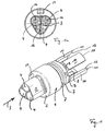
- FIG. 1 This in Fig. 1 shown cylindrical housing 1 has at its contact end 2 a shock protection 3.
- a mounted terminal contacts 16 in the case of the embodiment, a plug pins.
- Fig. 1 It can be seen that only the opening 4 shown on the top right is circular. The two other the terminal contacts 16 receiving openings have a deviating from the circular shape free form. This irregular freeform is used to create a plug coding. The aim of this plug-in coding is to be able to put together only technically constructive compatible connector to a plug-in coupling.
- the locking opening 17 for receiving, for example, a snap hook of a mechanical lock for the connector in the coupled state.
- connection end 5 of the housing 1 Facing away from the contact end 2 is the connection end 5 of the housing 1.
- the housing 1 has, at the connection end 5, a mounting stub 6 which springs back against the actual housing body.
- the mounting stub 6 carries two annular beads 7.
- the mounting stub 6 at the same time forms the opening edge of the passage opening 8 of the housing 1.
- On the front side of the mounting stub 6 are on film hinges. 9 Swivel paddle 10 stored.
- the swivel paddles 10 have flats 12 on their line-side narrow sides 11 facing away from the film hinges 9.
- the conductors 14 combined in the cable 13 are first connected to the connection contacts 16, namely crimped together.
- This prefabricated unit of terminal contacts 16 and conductors 14 then becomes what Fig. 2 shows, inserted through the passage opening 8 in the housing 1.
- Fig. 2 shows this insertion position of the cable connection terminal assembly.
- the shrink tube 15 is pushed over the mounting stub 6 and thus also over the radially projecting from the mounting stub ring beads 7 until it rests against the main body of the housing 1.
- the annular beads 7 fix the shrink tube 15 in his in Fig. 6 shown position before the heat treatment.
- Fig. 3 again shows the housing 1 without the prefabricated unit of the terminal contacts 16 and the conductors 14. Opposite the in Fig. 1 respectively.
- Fig. 2 illustrated embodiment are in the in Fig. 3 embodiment shown facing away from the housing 1 free ends of the pivot paddle 10 as predetermined breaking points effective injection points 18 formed. With the aid of these injection points 18, an auxiliary ring 19 is connected to the free ends of the swivel paddle 10. The auxiliary ring 19 serves as an assembly aid.
- the swivel paddle 10 are very easy to move. This complicates an automated assembly of the pre-assembled from the terminal contacts 16 and the conductors 17 unit.
- the tilt paddles 10 at the in FIG. 3 and FIG. 4 shown embodiment are designed trapezoidal. This trapezoidal configuration of the swivel paddle 10 is against the rectangular, in Fig. 1 . FIGS. 2 and 5 It is also conceivable, the auxiliary ring 19 with square shaped pivoting paddles 10 according to Fig. 1 . FIGS. 2 and 5 to combine.
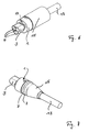
- the finished connector shows Fig. 7 ,
- the shrunken shrink tube 15 can be seen, the pivot paddles 10 in their in Fig. 5 holds shown clamping position.
- the shrink tube 15 is in this case clearly tapered from the housing 1 to the cable 13.
- Fig. 7 clearly visible the formed by the annular beads 7 positive connection between the housing 1 and shrink tube 15.
- the shrink tube 15 nestles both on the annular beads 7 and on the outer jacket of the cable 13 and thus at the same time forms a very tight rear cap for the connector.
Landscapes
- Details Of Connecting Devices For Male And Female Coupling (AREA)
- Cable Accessories (AREA)
- Connections By Means Of Piercing Elements, Nuts, Or Screws (AREA)
- Multi-Conductor Connections (AREA)
Description
- Die Erfindung betrifft einen elektrischen Steckverbinder gemäß dem Oberbegriff des Anspruchs 1. Derartige Steckverbinder haben ein Gehäuse mit einer Durchführungsöffnung für elektrische Leiter. An die Leiter angeschlossen sind elektrische Anschlusskontakte. Die Anschlußkontakte sind je nach Funktion als Steckerkontakte oder Buchsenkontakte ausgestaltet. Die Stecker- und Buchsenkontakte eines Steckerpaars sind dementsprechend kompatibel zueinander ausgebildet. Als Sonderbauform existieren auch Steckverbinder, die sowohl mit Stecker- als auch mit Buchsenkontakten bestückt sind. Schließlich sind auch sogenannte hermaphroditische Steckverbinder bekannt. Als elektrische Anschlusskontakte sind hier auch Schutzleiterkontakte mit umfasst. Die Verbindung der elektrischen Leiter des Steckverbinders mit den Anschlusskontakten ist als Crimpverbindung, Schraubverbindung, Klemmverbindung, Schneidklemmverbindung oder stoffschlüssige Verbindung, beispielsweise Lötverbindung oder Schweißverbindung ausgeführt.
- Im fertig montierten Zustand wird ein Steckverbinder üblicherweise mit einem hierzu komplementären anderen Steckverbinder zusammengesteckt. Beide Steckverbinder bilden dann eine elektrisch leitende Steckkupplung miteinander aus. Üblicherweise sind diese Steckkupplungen so ausgestaltet, dass sie beliebig oft montiert und demontiert werden können. Die jeweiligen Steckverbinder können also beliebig oft ineinander gesteckt und anschließend wieder auseinandergezogen werden.
- Beim Lösen der Steckverbindung, also beim Auseinanderziehen der die Kupplung bildenden Steckverbindung ist es jedoch problematisch, wenn der Bediener die Steckverbinder nicht am Gehäuse anfasst und dann auseinanderzieht, sondern das aus dem Gehäuse herausführende Leitungskabel umfasst und einen oder beide Steckverbinder beim Lösen der Steckverbindung am Leitungskabel zieht.
- Hierbei besteht die große Gefahr, dass die vorerwähnte Verbindung zwischen den einzelnen Leitern und den ihnen zugeordneten Kontakten beschädigt wird. Bei einer Beschädigung der Verbindung zwischen Leiter und Anschlusskontakt besteht vor allem die Gefahr, dass die anschließend wieder miteinander verkuppelten Steckverbinder scheinbar noch funktionsfähig sind und die Verbindung zwischen Anschlußkontakt und elektrischem Leiter während des Betriebs weiter zerstört wird. In Extremfällen kann dies zu Bränden oder ähnlichen Unglücksfällen führen.
- Es ist deshalb bekannt, am Steckverbinder eine Zugentlastung vorzusehen. Diese Zugentlastung hat die Funktion, eine in das Leitungskabel eingeleitete Zugkraft aufzunehmen, so dass diese von der Zugentlastung aufgefangen wird, so daß bei einem Auseinanderziehen der Verbindung an den Leitungskabeln eine Beschädigung der Verbindung zwischen den Leitern und den Anschlusskontakten unterbleibt.
- Aus der
DE-A-44 04 260 ist ein Steckverbinder mit einem als Zugentlastung wirksamen Schrumpfkörper bekannt. Im Bereich der Durchführungsöffnung für die elektrischen Leiter ist eine dort als Druckstück bezeichnete, mehrfach geschlitzte Hülse vorhanden. Über diese mehrfach geschlitzte Hülse wird ein Schrumpfschlauch aufgeschrumpft, um den Leiter gegen Zug zu sichern. Nachteilig bei dieser Ausführung ist die Tatsache, dass die infolge der Schlitzung gebildeten Hülsenarme durch die vom Schrumpfschlauch eingeleitete Kraft nur elastisch verformt werden. Ein Teil der vom Schrumpfschlauch eingeleiteten Kraft wird somit dafür verschwendet, die reversibel federartig verformten Hülsenarme in ihrer Montageendstellung zu halten. Mit anderen Worten neigen die Hülsenarme im Montageendzustand dazu, sich in ihre Ausgangsstellung zurück zu verformen. Eine derartige Rückverformung käme der Zerstörung der Zugentlastung gleich. - Aus der
US-A-3,920,306 ist schließlich ein Verbindungselement bekannt mit einer Kabeleinführung. An der Kabeleinführung sind wiederum elastisch verformbare Fixierzungen ausgebildet. Diese Fixierzungen tragen an ihren den Leitern zugewandten Innenflächen jeweils Vorsprünge zur formschlüssigen Fixierung der Leiter. Im Montageendzustand werden die Fixierzungen mit Hilfe von Zurrbändern vorgespannt, um die Leiter gegen ein Herausziehen zu sichern. Auch hier sind die Fixierzungen jeweils nur reversibel verformt mit der Folge, dass sie im Montageendzustand dazu tendieren, die Zugentlastung wieder zu lösen. -
DE 36 07 451 offenbart einem elektrischen Steckverbinder gemäß Oberbegriff des Anspruchs 1. - Der vorliegenden Erfindung liegt die Aufgabe zugrunde, einen elektrischen Steckverbinder mit einer gegenüber dem Stand der Technik verbesserten Zugentlastung anzugeben. Diese Aufgabe ist durch die Merkmalskombination des Anspruchs 1 gelöst. Die weiteren rückbezogenen Ansprüche beinhalten teilweise vorteilhafte und teilweise auch für sich selbst gesehen erfinderische Weiterbildungen der Erfindung.
- Nach seinem Anspruch 1 besteht der erfindungsmäßige elektrische Steckverbinder aus seinem Gehäuse und aus einer Durchgangsöffnung zur Einführung einer mehrere elektrische Leiter und einen Isoliermantel umfassenden Leitung in das Gehäuse. Der Grundgedanke der Erfindung besteht in einer als Reibgehemme ausgebildeten Zugentlastung. Die Klemmelemente des Reibgehemmes sind hierbei mindestens zwei die Leitung zwischen sich klemmend fixierende Klemmbacken, welche ihrerseits am Gehäuse fixiert sind sowie ein die Klemmbacken in ihrer Montageendstellung mit der Klemmkraft beaufschlagender Schrumpfkörper. Der die Klemmbacken in ihrer Montageendstellung fixierende Schrumpfkörper dient folglich als Kraftspeicher für die Klemmverbindung.
- Ein Vorteil der Erfindung liegt in der einfachen Montage des Steckverbinders. Zunächst werden die vorzugsweise mit elektrischen Anschlusskontakten bereits vorkonfektionierten Leiter in das Gehäuse eingebracht. Anschließend muss nur noch der Schrumpfkörper aufgeschrumpft werden. Während des Aufschrumpfens drückt der Schrumpfkörper zugleich die Klemmbacken an die aus dem Gehäuse hinausstehende Mantelleitung. Der Schrumpfkörper hat also eine Doppelfunktion. Zum einen bringt er die Klemmbacken aus ihrer Ausgangsstellung in ihre die Leiter klemmende Montageendstellung. Zum anderen dient der Schrumpfkörper in dieser Montageendstellung als Kraftspeicher für das Reibgehemme. Hinsichtlich der Wirkungsweise der hier erwähnten Reibgehemme sei verwiesen auf "Krause" Konstruktionselemente der Feinmechanik", 2. Auflage, Karl Hanser Verlag München - wie 1993 (ISBN 3-446-16530-4).
- Die schwenkbare Lagerung der Klemmbacken hat den Vorteil, dass sich die Klemmbacken während des Schrumpfungsprozesses des Schrumpfkörpers kontinuierlich und ohne Widerstand auf das Leitungskabel zubewegen können und sich kontinuierlich an den äußeren Isoliermantel der Leitung anschmiegen. Diese Maßnahme begünstigt die Montage und den Toleranzausgleich während der Montage gleichermaßen.
- Ein weiterer Vorteil der Erfindung liegt somit in der stufenlosen Anpassbarkeit der Zugentlastung an den Außendurchmesser der zu fixierenden Leiter bzw. des äußeren Isoliermantels, also der zu fixierenden Leitung. Infolge dieser stufenlosen Anpassbarkeit sind mögliche Toleranzschwankungen von vornherein ausgeglichen. Die Schrumpfverbindung gewährleistet deshalb einen durchgängigen Toleranzausgleich bei der Massenfertigung von Steckverbindern. Schließlich ist die Montage vereinfacht, weil außer den Klemmbacken nur ein einziges weiteres Teil zur Realisierung der Zugentlastung erforderlich ist. Weitere Teile wie Schrauben oder Ähnliches entfallen. Schließlich ist die so geschaffene Zugentlastung auch manipulationssicher, weil der Schrumpfkörper ohne Beschädigung bzw. irreversible Zerstörung in der Regel nicht mehr vom Steckverbinder entfernt werden kann.
- Die Ansprüche 2 bis 6 betreffen Weiterbildungen der Klemmbacken. Die in Anspruch 2 vorgeschlagene Fixierung der Klemmbacken im Bereich des Öffnungsrandes der Durchführungsöffnung sorgt für eine Verlagerung der Wirkstellen des Reibgehemmes an denjenigen Bereich des Gehäuses, aus welchem das Leitungskabel austritt.
- Die in Anspruch 3 vorgeschlagene rechteckförmige Ausgestaltung der Klemmbacken verleiht ihnen einen sehr großen wirksamen Hebelarm. Außerdem begünstigt diese rechteckförmige Ausgestaltung die kontinuierliche Verjüngung des insbesondere als Schrumpfschlauch ausgebildeten Schrumpfkörpers vom Gehäuse mit tendenziell größerem Durchmesser hin zum Leitungskabel mit tendenziell kleinerem Durchmesser als das Gehäuse.
- Nach Anspruch 4 sind die Klemmbacken als Schwenkpaddel ausgestaltet und jeweils mittels eines Filmscharniers mit ihrer scharnierseitigen Schmalseite am Gehäuse fixiert und schwenkbar gelagert. Die Verwendung eines Filmscharniers gewährleistet eine besonders zuverlässige und widerstandsfreie Verschwenkung der Schwenkpaddel in Richtung auf das zu beaufschlagende Leitungskabel. Das Filmscharnier läßt eine gewissermaßen irreversibel und ohne wesentliche Kraft durchführbare Verschwenkung des Schwenkpaddels in Richtung auf das Leitungskabel zu. Das Schwenkpaddel ist dadurch dauerhaft in Richtung auf das Leitungskabel verschwenkt und setzt dem Schrumpfschlauch keine Federkräfte oder ähnliche Rückstellkräfte entgegen, um in seine Ausgangsstellung zurückzuschwenken.
- Anspruch 5 betrifft eine Weiterbildung der schwenkpaddelartig ausgebildeten Klemmbacken. Hierbei wirken letztlich nur die Stirnflächen der leitungsseitigen Schmalseite der Schwenkpaddel als auf das Leitungskabel einwirkende Klemmflächen, während die übrige Rechteckfläche der Schwenkpaddel zum einen als Hebelarm für eine gute Kraftübertragung und zum anderen als Schutz für die Leiter bzw. das Leitungskabel im Bereich der Durchgangsöffnung wirksam ist. Schließlich wirken die rechteckförmigen Schwenkpaddel zusätzlich als stützendes Skelett innerhalb des aufgeschrumpften Schrumpfkörpers, insbesondere des aufgeschrumpften Schrumpfschlauchs und bilden dadurch einen freien Anschlussraum für die einzelnen Leiter, ohne die Leiter mit irgendwelchen Kräften zu beaufschlagen.
- Anspruch 6 beinhaltet eine weitere Anpassung der Schwenkpaddel an die zylindrischen bzw. gerundeten Außenkonturen des Leitungskabels.
- Nach Anspruch 7 ist schließlich vorgeschlagen, auch auf den Außenflächen der Klemmbacken, insbesondere der als Schwenkpaddel ausgestalteten Klemmbacken Formvorsprünge vorzusehen. Diese Formvorsprünge dienen zur verbesserten Fixierung des Schrumpfschlauches sowohl bei der Montage als auch im Montageendzustand. Bei der Vormontage dienen die Formvorsprünge als formschlüssige Vorfixierung für den Schrumpfschlauch während des Schrumpfvorganges. Nach dem Schrumpfen verkrallt sich das Schlauchmaterial in den zwischen den Formvorsprüngen gebildeten Vertiefungen. Die kraftschlüssige Schrumpfverbindung wird somit noch durch eine zusätzliche formschlüssige Verbindung zwischen dem Schrumpfschlauchmaterial und den Formvorsprüngen ergänzt.
- Nach der Lehre des Anspruchs 8 sind auf den Innenflächen der Klemmbacken Profilvorsprünge vorgesehen. Diese Profilvorsprünge dienen zur Profilierung der Klemmbakken, um eine möglichst hohe Reibung zwischen den Klemmbacken einerseits und der von ihnen geklemmten Leitung andererseits zu erhöhen. Die Profilvorsprünge dienen also zur Erhöhung des Wirkungsgrads des als Zugentlastung wirksamen Reibgehemmes. Die Profilvorsprünge können hierbei als Spitzen, Krallen, Rippen oder Nuten ausgeführt sein. Es sind auch andere geometrische Formen von geeigneten Profilvorsprüngen denkbar. Neben der Funktion als Zugentlastung dienen diese Profilvorsprünge zudem auch als Schubentlastung und insbesondere als Verdrehsicherung für das Leitungskabel im Schrumpfkörper. Insbesondere die Verdrehsicherung verhindert Undichtigkeiten in dem Bereich, in welchem der als rückwärtige Verschlusskappe wirksame Schrumpfschlauch am Außenmantel des Leitungskabels bündig anliegt.
- Die Ansprüche 10 bis 12 betreffen eine Montagehilfe für die Klemmbacken. Infolge der schwenkbaren, beweglichen Lagerung der Klemmbacken am Gehäuse besteht bei der automatisierten Fertigung die Gefahr, dass die Klemmbacken ihre Position vor der Montage, insbesondere vor dem Aufschrumpfen des Schrumpfkörpers ungewollt verändern. In Anspruch 10 ist deshalb vorgeschlagen, die Klemmbacken über Montagehilfen miteinander zu verbinden, um sie in ihrer geöffneten Position zunächst zu halten. Die Montagehilfe ist mit den Klemmbacken über Sollbruchstellen verbunden, so dass sie vor der Endmontage problemlos entfernt werden kann.
- Vorteilhaft ist die Montagehilfe als Hilfsring ausgestaltet (Anspruch 11). Dieser Hilfsring kann über einfache Verbindungspunkte an den Klemmbacken angespritzt werden. Vor der Endmontage werden die Verbindungspunkte einfach durchbrochen und der Hilfsring so von den Klemmbacken entfernt. Besonders vorteilhaft wird der Hilfsring am Freiende der Klemmbacken angespritzt, welches dem Gehäuse abgewandt ist. Auf diese Weise kann der Hilfsring ganz einfach endseitig von den Klemmbacken abgebrochen werden. Zudem gewährleistet der Hilfsring an den Freienden eine sehr sichere Fixierung der Klemmbacken in ihrer geöffneten Position und entfaltet somit seine Wirkung als Montagehilfe besonders effektiv.
- Die im Anspruch 13 vorgeschlagene Ausbildung des Schrumpfkörpers als Schrumpfschlauch hat den Vorteil, dass der Schrumpfschlauch einfach über die vorzugsweise mit den Anschlusskontakten vorkonfektionierten Leiter geschoben werden kann bzw. die Leiter einfach durch den Schrumpfschlauch hindurchgeschoben werden können. Des Weiteren kann der Schrumpfschlauch auf einen am Gehäuse vorgesehenen zylinderförmigen Anschlussflansch oder Montagestutzen aufgeschoben werden zur Vormontage vor dem Schrumpfen. Die Ausgestaltung als Schrumpfschlauch erleichtert die Montage des Schrumpfkörpers folglich. In weiterer Ausgestaltung nach Anspruch 14 kann der Schrumpfschlauch zugleich als Verschlusskappe für die Durchführungsöffnung verwendet werden. Dadurch, dass sich der Schrumpfschlauch sowohl an einen entsprechend ausgebildeten Öffnungsrand der Durchführungsöffnung einerseits und die äußere Ummantelung der Leiter andererseits fest anschmiegt, können sogar hohe Dichtigkeitsanforderungen realisiert werden. Der Schrumpfschlauch hat neben seiner Funktion als Kraftspeicher für das Reibgehemme noch die Funktion einer Abdichtkappe für die Durchführungsöffnung. Zur Erhöhung der Dichtigkeit zwischen dem Schrumpfschlauch und dem Öffnungsrand der Durchführungsöffnung einerseits und dem Leitungsmantel andererseits kann die Innenseite des Schrumpfschlauches gegebenenfalls mit einer geeigneten Klebemasse versehen sein, wodurch eine unlösbare und spaltfreie Verbindung der Einzelteile entsteht.
- Die Ansprüche 15 und 16 beinhalten Weiterbildungen des Gehäuses zur besseren Fixierung des Schrumpfschlauchs sowohl bei der Montage als auch im Montageendzustand. Bei der Vormontage dienen die Formvorsprünge bzw. die Ringwülste als formschlüssige Vorfixierung für den Schrumpfschlauch während des Schrumpfvorgangs. Nach dem Schrumpfen verkrallt sich das Schlauchmaterial in den zwischen den Formvorsprüngen gebildeten Vertiefungen, welche im Falle der Ringwülste gemäß Anspruch 16 als Ringnuten ausgestaltet sind. Neben der kraftschlüssigen Schrumpfverbindung kommt noch ein zusätzlicher Formschluss zwischen Schrumpfschlauchmaterial und den Formvorsprüngen bzw. Ringwülsten hinzu.
- Anspruch 17 betrifft eine Ausführungsform des Steckverbinders mit einem zylinderförmigen Steckergehäuse und mit an diese Zylinderform besonders angepassten als Schwenkpaddel ausgestalteten Klemmbacken.
- Anhand eines in den Zeichnungsfiguren dargestellten Ausführungsbeispiels wird die Erfindung weiter erläutert. Es zeigen:
- Fig. 1
- das leere Gehäuse des Steckverbinders mit angeformtem Schwenkpad- del,
- Fig. 1a
- eine Draufsicht auf das Kontaktende des Gehäuses gemäß Pfeil I in
Fig. 1 mit bereits eingeschobenen Anschlusskontakten, - Fig. 2
- das Gehäuse gemäß
Fig. 1 mit eingeschobenem Leitungskabel und daran bereits vorkonfektionierten Anschlusskontakten, - Fig. 3
- das Gehäuse gemäß
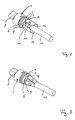
Fig. 1 in einer Ausführungsform mit punktförmig an- gespritztem Hilfsring an den Klemmbacken, - Fig. 4
- das Gehäuse gemäß
Fig. 3 nach dem Entfernen des Hilfsrings, - Fig. 5
- die in
Fig. 2 gezeigte Gehäuse-, Leitungs- bzw. Anschlusskontaktkombi- nation mit in den Montageendzustand verschwenkten Schwenkpaddeln, - Fig. 6
- die Anordnung gemäß
Fig. 5 mit aufgeschobenem Schrumpfschlauch vor der Wärmebehandlung sowie - Fig. 7
- den fertigen Steckverbinder.
- Das in
Fig. 1 dargestellte zylinderförmige Gehäuse 1 weist an seinem Kontaktende 2 einen Berührungsschutz 3 auf. In den Öffnungen 4 des Berührungsschutzes 3 liegen die inFig. 1 a montierten Anschlusskontakte 16, im Falle des Ausführungsbeispiels Steckerstifte ein. InFig. 1 a ist erkennbar, dass nur die oben rechts dargestellte Öffnung 4 kreisrund ist. Die beiden anderen die Anschlusskontakte 16 aufnehmenden Öffnungen haben eine von der Kreisform abweichende Freiform. Diese unregelmäßige Freiform dient zur Schaffung einer Steckkodierung. Ziel dieser Steckkodierung ist es, nur technisch konstruktiv miteinander kompatible Steckverbinder zu einer Steckkupplung zusammenstecken zu können. InFig. 1a schließlich erkennbar ist die Verriegelungsöffnung 17 zur Aufnahme beispielsweise eines Schnapphakens einer mechanischen Verriegelung für die Steckverbinder im gekoppelten Zustand. - Dem Kontaktende 2 abgewandt ist das Anschlussende 5 des Gehäuses 1. Das Gehäuse 1 weist zum Anschlussende 5 einen gegenüber dem eigentlichen Gehäusekörper zurückspringenden Montagestutzen 6 auf. Der Montagestutzen 6 trägt zwei Ringwülste 7. Der Montagestutzen 6 bildet zugleich den Öffnungsrand der Durchführungsöffnung 8 des Gehäuses 1. Auf der Stirnseite des Montagestutzens 6 sind an Filmscharnieren 9 Schwenkpaddel 10 gelagert. Die Schwenkpaddel 10 weisen an ihren den Filmscharnieren 9 abgewandten leitungsseitigen Schmalseiten 11 jeweils Abflachungen 12 auf.
- Zur Montage des Steckverbinders werden die im Leitungskabel 13 zusammengefassten Leiter 14 zunächst mit den Anschlusskontakten 16 verbunden, nämlich zusammengecrimpt. Diese vorkonfektionierte Einheit aus Anschlusskontakten 16 und Leitern 14 wird sodann, was
Fig. 2 zeigt, durch die Durchführungsöffnung 8 in das Gehäuse 1 eingeschoben.Fig. 2 zeigt diese Einschubstellung der Leitungskabel-Anschlusskontakt-Baugruppe. Sodann wird der Schrumpfschlauch 15 über den Montagestutzen 6 und somit auch über die aus dem Montagestutzen radial hervorstehenden Ringwülste 7 geschoben bis er am Grundkörper des Gehäuses 1 anliegt. Die Ringwülste 7 fixieren den Schrumpfschlauch 15 in seiner inFig. 6 dargestellten Stellung vor der Wärmebehandlung. -
Fig. 3 zeigt wiederum das Gehäuse 1 ohne die vorkonfektionierte Einheit aus den Anschlusskontakten 16 und den Leitern 14. Gegenüber der inFig. 1 bzw.Fig. 2 dargestellten Ausführungsform sind bei der inFig. 3 dargestellten Ausführungsform an den dem Gehäuse 1 abgewandten Freienden der Schwenkpaddel 10 als Sollbruchstellen wirksame Spritzpunkte 18 angeformt. Mit Hilfe dieser Spritzpunkte 18 ist ein Hilfsring 19 mit den Freienden der Schwenkpaddel 10 verbunden. Der Hilfsring 19 dient als Montagehilfe. Infolge der Lagerung der Schwenkpaddel 10 an den Filmscharnieren 9 sind die Schwenkpaddel 10 nämlich sehr leicht beweglich. Dies erschwert eine automatisierte Montage der aus den Anschlusskontakten 16 und den Leitern 17 vorkonfektionierten Einheit. - Zur Endmontage dieser Ausführungsform wird die aus Anschlusskontakten 16 und Leitern 14 bestehende vorkonfektionierte Einheit durch die Durchführungsöffnung 8 in das Gehäuse 1 eingeschoben. Sodann wird der Hilfsring 19 mittels Durchbrechen der perforationsartigen Spritzpunkte 18 von den Schwenkpaddeln 10 abgetrennt (
Fig. 4 ). Sodann wird der Schrumpfschlauch 15 über den Montagestutzen 6 sowie die Ringwülste 7 geschoben, bis er am Grundkörper des Gehäuses 1 anliegt. Sodann erfolgt derselbe Schrumpfprozess wie bei der Ausführungsform gemäßFig. 1 undFig. 2 . - Es sei noch angemerkt, dass die Schwenkpaddel 10 bei der in
Fig. 3 und Fig. 4 gezeigten Ausführungsform trapezförmig ausgestaltet sind. Diese trapezförmige Ausgestaltung der Schwenkpaddel 10 ist gegen die rechteckförmige, inFig. 1 ,Fig. 2 und Fig. 5 gezeigte rechteckförmige Ausgestaltung beliebig austauschbar unabhängig von der Anbringung des Hilfsrings 19. Es ist also auch denkbar, den Hilfsring 19 mit rechteckförmig ausgestalteten Schwenkpaddeln 10 gemäßFig. 1 ,Fig. 2 und Fig. 5 zu kombinieren. - Infolge der Wärmebehandlung schrumpft das Material des Schrumpfschlauchs 15 zusammen. Durch die Schrumpfung des Materials des Schrumpfschlauchs 15 werden zugleich die Klemmkräfte auf die Schwenkpaddel 10 übertragen. Infolge der Schrumpf- bzw. Klemmkräfte schwenken die Schwenkpaddel 10 um ihre Filmscharniere 9 in Richtung auf das Leitungskabel 13 bis sie ihre Montageendstellung erreicht haben, in der ihre den Filmscharnieren 9 abgewandte Stirnseiten mit den Abflachungen 12 am Außenmantel des Leitungskabels 13 fest anliegen. Diese Anlagestellung der Abflachungen 12 der Schwenkpaddel 10 zeigt
Fig. 3 . InFig. 5 ist gut erkennbar, dass sich die Abflachungen 12 wegen ihrer Konkavität besonders gut an den Außenmantel des Leitungskabels 13 anschmiegen und dabei die Klemmkraft über den großen Hebelarm zwischen dem Filmscharnier 9 und der leitungsseitigen Schmalseite 11 der Schwenkpaddel 10 übertragen.Fig. 5 zeigt also die Montageendstellung der Schwenkpaddel 10 bei nachträglich entferntem Schrumpfschlauch 15. - Den fertigen Steckverbinder hingegen zeigt
Fig. 7 . Dort ist zum einen der geschrumpfte Schrumpfschlauch 15 erkennbar, der die Schwenkpaddel 10 in ihrer inFig. 5 dargestellten Klemmstellung hält. Der Schrumpfschlauch 15 ist hierbei vom Gehäuse 1 zum Leitungskabel 13 hin deutlich verjüngt. Ferner ist inFig. 7 gut erkennbar der durch die Ringwülste 7 gebildete Formschluss zwischen Gehäuse 1 und Schrumpfschlauch 15. Der Schrumpfschlauch 15 schmiegt sich sowohl an die Ringwülste 7 als auch an den Außenmantel des Leitungskabels 13 an und bildet somit zugleich eine sehr dichte rückwärtige Verschlusskappe für den Steckverbinder. -
- 1
- Gehäuse
- 2
- Kontaktende
- 3
- Berührungsschutz
- 4
- Öffnung
- 5
- Anschlussende
- 6
- Montagestutzen
- 7
- Ringwulst
- 8
- Durchführungsöffnung
- 9
- Filmscharnier
- 10
- Schwenkpaddel
- 11
- leitungsseitige Schmalseite
- 12
- Abflachung
- 13
- Leitungskabel
- 14
- Leiter
- 15
- Schrumpfschlauch
- 16
- Anschlusskontakt
- 17
- Verriegelungsöffnung
- 18
- Spritzpunkt
- 19
- Hilfsring
Claims (17)
- Elektrischer Steckverbinder mit einem Gehäuse (1),• mit einer Durchführungsöffnung (8) für eine elektrische Leiter (14) umfassende Leitung (13),• mit mindestens zwei die Leitung (13) zwischen sich fixierenden Klemmbacken am Gehäuse und• wobei die Klemmbacken am Gehäuse (1) schwenkbar gelagert sind,
dadurch gekennzeichnet, daß das Gehäuse mit einem die Klemmbacken mit der Klemmkraft beaufschlagenden und in ihrer Klemmstellung fixierenden Schrumpfkörper als Zugentlastung für die Leitung (13) ausgerüstet ist. - Steckverbinder nach Anspruch 1,
dadurch gekennzeichnet,
dass die Klemmbacken am Öffnungsrand der Durchführungsöffnung (8) fixiert sind. - Steckverbinder nach Anspruch 2,
gekennzeichnet durch
im wesentlichen rechteckförmige Schwenkpaddel (10) als Klemmbacken. - Steckverbinder nach Anspruch 3,
dadurch gekennzeichnet,
dass die Schwenkpaddel (10) jeweils mittels eines Filmscharniers (9) mit einer scharnierseitigen Schmalseite am Gehäuse (1) schwenkgelagert sind. - Steckverbinder nach Anspruch 4,
dadurch gekennzeichnet,
dass die Stirnfläche der der scharnierseitigen Schmalseite abgewandten leitungsseitigen Schmalseite (11) Abflachungen (12) aufweist zur Bildung einer Klemmfläche. - Steckverbinder nach Anspruch 5,
dadurch gekennzeichnet,
dass die Schwenkpaddel (10) und deren Abflachungen (12) konkav gekrümmt sind zur flächigen Anschmiegung an das Leitungskabel (13). - Steckverbinder nach einem der Ansprüche 1 bis 6,
gekennzeichnet durch
Formvorsprünge auf den dem Schrumpfkörper zugewandten Außenflächen der Schwenkpaddel (10). - Steckverbinder nach einem der Ansprüche 1 bis 7,
gekennzeichnet durch
Profilvorsprünge auf den Klemmbacken zur Steigerung der zwischen den Leitern (14) und den Klemmbacken wirksamen Reibung. - Steckverbinder nach Anspruch 8,
gekennzeichnet durch
Profilvorsprünge auf den Abflachungen (12). - Steckverbinder nach einem der Ansprüche 1 bis 9,
dadurch gekennzeichnet,
dass eine sollbruchstellenaufweisende Montagehilfe die Klemmbacken in ihrer geöffneten Position miteinander verbinden. - Steckverbinder nach Anspruch 10,
gekennzeichnet durch
einen an als Sollbruchstellen wirksamen Verbindungspunkten (18) an die Klemmbacken angespritzten Hilfsring 19 als Montagehilfe. - Steckverbinder nach Anspruch 11,
dadurch gekennzeichnet,
dass der Hilfsring (19) an den dem Gehäuse (1) abgewandten Freienden der Klemmbacken angespritzt ist. - Steckverbinder nach einem der Ansprüche 1 bis 12,
gekennzeichnet durch
einen Schrumpfschlauch (15) als Schrumpfkörper. - Steckverbinder nach Anspruch 13,
dadurch gekennzeichnet,
dass der Schrumpfschlauch (15) die Leitung (13) tüllenartig umschließt und eine Abdichtkappe für die Durchführungsöffnung (8) bildet. - Steckverbinder nach Anspruch 13 oder Anspruch 14,
gekennzeichnet durch
Formvorsprünge am Gehäuse (1) zur zusätzlichen formschlüssigen Fixierung des Schrumpfschlauchs (15) am Gehäuse (1). - Steckverbinder nach Anspruch 15,
dadurch gekennzeichnet,
dass die Formvorsprünge als Ringwülste 7 ausgebildet sind. - Steckverbinder nach einem der Ansprüche 1 bis 16,
gekennzeichnet durch
ein zylinderförmiges Gehäuse (1) mit einem Kontaktende (2) mit Anschlusskontakten (16), mit einem dem Kontaktende (2) abgewandten Anschlussende (5) mit der Durchführungsöffnung (8) und mit mehreren, vorzugsweise vier nach Art von Zähnen einer Stirnverzahnung vom Öffnungsrand der Durchführungsöffnung (8) abstehenden Schwenkpaddeln (10).
Priority Applications (1)
| Application Number | Priority Date | Filing Date | Title |
|---|---|---|---|
| PL04720532T PL1604431T3 (pl) | 2003-03-15 | 2004-03-13 | Elektryczne złącze wtykowe |
Applications Claiming Priority (3)
| Application Number | Priority Date | Filing Date | Title |
|---|---|---|---|
| DE10311507 | 2003-03-15 | ||
| DE10311507A DE10311507B4 (de) | 2003-03-15 | 2003-03-15 | Elektrischer Steckverbinder |
| PCT/EP2004/002645 WO2004084359A1 (de) | 2003-03-15 | 2004-03-13 | Elektrischer steckverbinder |
Publications (2)
| Publication Number | Publication Date |
|---|---|
| EP1604431A1 EP1604431A1 (de) | 2005-12-14 |
| EP1604431B1 true EP1604431B1 (de) | 2009-06-24 |
Family
ID=32920824
Family Applications (1)
| Application Number | Title | Priority Date | Filing Date |
|---|---|---|---|
| EP04720532A Expired - Lifetime EP1604431B1 (de) | 2003-03-15 | 2004-03-13 | Elektrischer steckverbinder |
Country Status (6)
| Country | Link |
|---|---|
| EP (1) | EP1604431B1 (de) |
| AT (1) | ATE434844T1 (de) |
| DE (2) | DE10311507B4 (de) |
| ES (1) | ES2325991T3 (de) |
| PL (1) | PL1604431T3 (de) |
| WO (1) | WO2004084359A1 (de) |
Families Citing this family (4)
| Publication number | Priority date | Publication date | Assignee | Title |
|---|---|---|---|---|
| DE102005032593B4 (de) * | 2005-07-11 | 2007-07-26 | Technische Universität Berlin | Optisches Modul mit einer Leichtleitfaser und einem lichtemittierenden/lichtempfangenden Bauteil und Verfahren zum Herstellen |
| DE202009015571U1 (de) | 2009-11-14 | 2011-03-24 | Wieland Electric Gmbh | Elektrischer Steckverbinder |
| DE102011000332A1 (de) | 2011-01-26 | 2012-07-26 | Phoenix Contact Gmbh & Co. Kg | Elektrischer Steckverbinder |
| DE102022106349A1 (de) | 2022-03-18 | 2023-09-21 | Audi Aktiengesellschaft | Leiteranordnung für einen Energiespeicher eines Kraftfahrzeugs, Energiespeicher, Bordnetz und Kraftfahrzeug |
Family Cites Families (7)
| Publication number | Priority date | Publication date | Assignee | Title |
|---|---|---|---|---|
| NL6714664A (de) * | 1966-11-03 | 1968-05-06 | ||
| US3920306A (en) * | 1974-10-02 | 1975-11-18 | Amp Inc | Tap connections for multi-conductor cables |
| DE3607451A1 (de) * | 1986-03-07 | 1987-09-17 | Rose Walter Gmbh & Co Kg | Vorrichtung zur festlegung von kabeln in kabeleingangsstutzen |
| FR2612699B1 (fr) * | 1987-03-20 | 1994-06-03 | Sigmaform Corp | Capot pour connecter un cable electrique a un autre dispositif electrique et son procede de fabrication et de montage du capot et de la connexion |
| DE4404260A1 (de) * | 1994-02-10 | 1995-08-17 | W W Fischer Sa | Elektrische Steckverbindung, insbesondere für die Medizintechnik |
| US5743759A (en) * | 1996-09-26 | 1998-04-28 | Hubbell Incorporated | Electrical connector with substantially flush mounted cord seal |
| EP1037325A3 (de) * | 1999-03-17 | 2000-09-27 | Spinner GmbH Elektrotechnische Fabrik | Kabelzugentlastung |
-
2003
- 2003-03-15 DE DE10311507A patent/DE10311507B4/de not_active Expired - Fee Related
-
2004
- 2004-03-13 WO PCT/EP2004/002645 patent/WO2004084359A1/de not_active Ceased
- 2004-03-13 DE DE502004009651T patent/DE502004009651D1/de not_active Expired - Lifetime
- 2004-03-13 AT AT04720532T patent/ATE434844T1/de not_active IP Right Cessation
- 2004-03-13 EP EP04720532A patent/EP1604431B1/de not_active Expired - Lifetime
- 2004-03-13 PL PL04720532T patent/PL1604431T3/pl unknown
- 2004-03-13 ES ES04720532T patent/ES2325991T3/es not_active Expired - Lifetime
Also Published As
| Publication number | Publication date |
|---|---|
| DE10311507A1 (de) | 2004-09-30 |
| WO2004084359A1 (de) | 2004-09-30 |
| DE10311507B4 (de) | 2006-09-14 |
| ES2325991T3 (es) | 2009-09-28 |
| ATE434844T1 (de) | 2009-07-15 |
| DE502004009651D1 (de) | 2009-08-06 |
| PL1604431T3 (pl) | 2009-12-31 |
| EP1604431A1 (de) | 2005-12-14 |
Similar Documents
| Publication | Publication Date | Title |
|---|---|---|
| DE69418156T2 (de) | Umhüllung mit Abdichtung für Koaxialkabelverbindung | |
| EP1317025B1 (de) | Belastbare Steckeranordnung für Datenkabel, insbesondere RJ-45-Verbinder | |
| EP1034583B1 (de) | Einrichtung zum anschliessen und verbinden einer leitung | |
| EP2442403B1 (de) | Schraubenlose Anschlussklemme | |
| EP1552582B1 (de) | Elektrischer steckverbinder | |
| EP2301117B1 (de) | Verbindersystem, verwendung und verfahren | |
| EP2932566B1 (de) | Autoladestecker | |
| EP2580818B1 (de) | Steckverbindung für die übertragung elektrischer energie | |
| WO2013135698A1 (de) | Elektrische wanddurchführung für solaranlagen | |
| DE102007055040B4 (de) | Kontaktelement und Verfahren zur Herstellung eines Kontaktelementes | |
| WO2011151393A1 (de) | Kontaktelement für steckeranordnung | |
| DE102014115595B3 (de) | Stecker und Gegenstecker | |
| DE2647043C2 (de) | Zugentlastungsvorrichtung für eine Kabeleinführung in ein Gehäuse eines elektrischen Gerätes | |
| EP2234215A1 (de) | Steckergehäuse aus Kunststoff für einen Steckverbinder | |
| EP2084784A2 (de) | Steckverbindung, insbesondere für sensor-/aktorleitungen | |
| WO2011128076A1 (de) | Vorrichtung zum elektrischen verbinden eines kabels, insbesondere steckverbindungsteil mit einem schirmkontaktelement | |
| EP2410613B1 (de) | Rundsteckverbinder | |
| EP3261109B1 (de) | Sicherungsvorrichtung | |
| EP2658040B1 (de) | Stecker | |
| DE3108744A1 (de) | Mehrpolige elektrische steckverbindung | |
| EP1072067A1 (de) | Schraubenlose steckverbindung | |
| DE10311507B4 (de) | Elektrischer Steckverbinder | |
| DE102008009620A1 (de) | Steckverbinderelement mit Abdichtung im Kabelanschlußbereich | |
| DE102022122506A1 (de) | Universell einsetzbares Gehäuse zur Abdeckung von Kontaktelementen | |
| EP2451021A2 (de) | Gehäuse für einen Steckverbinder |
Legal Events
| Date | Code | Title | Description |
|---|---|---|---|
| PUAI | Public reference made under article 153(3) epc to a published international application that has entered the european phase |
Free format text: ORIGINAL CODE: 0009012 |
|
| 17P | Request for examination filed |
Effective date: 20051006 |
|
| AK | Designated contracting states |
Kind code of ref document: A1 Designated state(s): AT BE BG CH CY CZ DE DK EE ES FI FR GB GR HU IE IT LI LU MC NL PL PT RO SE SI SK TR |
|
| AX | Request for extension of the european patent |
Extension state: AL LT LV MK |
|
| DAX | Request for extension of the european patent (deleted) | ||
| GRAP | Despatch of communication of intention to grant a patent |
Free format text: ORIGINAL CODE: EPIDOSNIGR1 |
|
| GRAS | Grant fee paid |
Free format text: ORIGINAL CODE: EPIDOSNIGR3 |
|
| GRAA | (expected) grant |
Free format text: ORIGINAL CODE: 0009210 |
|
| AK | Designated contracting states |
Kind code of ref document: B1 Designated state(s): AT BE BG CH CY CZ DE DK EE ES FI FR GB GR HU IE IT LI LU MC NL PL PT RO SE SI SK TR |
|
| REG | Reference to a national code |
Ref country code: GB Ref legal event code: FG4D Free format text: NOT ENGLISH |
|
| REG | Reference to a national code |
Ref country code: CH Ref legal event code: EP |
|
| REG | Reference to a national code |
Ref country code: IE Ref legal event code: FG4D Free format text: LANGUAGE OF EP DOCUMENT: GERMAN |
|
| REF | Corresponds to: |
Ref document number: 502004009651 Country of ref document: DE Date of ref document: 20090806 Kind code of ref document: P |
|
| REG | Reference to a national code |
Ref country code: ES Ref legal event code: FG2A Ref document number: 2325991 Country of ref document: ES Kind code of ref document: T3 |
|
| REG | Reference to a national code |
Ref country code: SE Ref legal event code: TRGR |
|
| PG25 | Lapsed in a contracting state [announced via postgrant information from national office to epo] |
Ref country code: SI Free format text: LAPSE BECAUSE OF FAILURE TO SUBMIT A TRANSLATION OF THE DESCRIPTION OR TO PAY THE FEE WITHIN THE PRESCRIBED TIME-LIMIT Effective date: 20090624 |
|
| REG | Reference to a national code |
Ref country code: PL Ref legal event code: T3 |
|
| PG25 | Lapsed in a contracting state [announced via postgrant information from national office to epo] |
Ref country code: CZ Free format text: LAPSE BECAUSE OF FAILURE TO SUBMIT A TRANSLATION OF THE DESCRIPTION OR TO PAY THE FEE WITHIN THE PRESCRIBED TIME-LIMIT Effective date: 20090624 Ref country code: EE Free format text: LAPSE BECAUSE OF FAILURE TO SUBMIT A TRANSLATION OF THE DESCRIPTION OR TO PAY THE FEE WITHIN THE PRESCRIBED TIME-LIMIT Effective date: 20090624 |
|
| REG | Reference to a national code |
Ref country code: IE Ref legal event code: FD4D |
|
| PG25 | Lapsed in a contracting state [announced via postgrant information from national office to epo] |
Ref country code: SK Free format text: LAPSE BECAUSE OF FAILURE TO SUBMIT A TRANSLATION OF THE DESCRIPTION OR TO PAY THE FEE WITHIN THE PRESCRIBED TIME-LIMIT Effective date: 20090624 |
|
| PG25 | Lapsed in a contracting state [announced via postgrant information from national office to epo] |
Ref country code: BG Free format text: LAPSE BECAUSE OF FAILURE TO SUBMIT A TRANSLATION OF THE DESCRIPTION OR TO PAY THE FEE WITHIN THE PRESCRIBED TIME-LIMIT Effective date: 20090924 Ref country code: PT Free format text: LAPSE BECAUSE OF FAILURE TO SUBMIT A TRANSLATION OF THE DESCRIPTION OR TO PAY THE FEE WITHIN THE PRESCRIBED TIME-LIMIT Effective date: 20091024 |
|
| PG25 | Lapsed in a contracting state [announced via postgrant information from national office to epo] |
Ref country code: IE Free format text: LAPSE BECAUSE OF FAILURE TO SUBMIT A TRANSLATION OF THE DESCRIPTION OR TO PAY THE FEE WITHIN THE PRESCRIBED TIME-LIMIT Effective date: 20090624 Ref country code: DK Free format text: LAPSE BECAUSE OF FAILURE TO SUBMIT A TRANSLATION OF THE DESCRIPTION OR TO PAY THE FEE WITHIN THE PRESCRIBED TIME-LIMIT Effective date: 20090624 |
|
| PLBE | No opposition filed within time limit |
Free format text: ORIGINAL CODE: 0009261 |
|
| STAA | Information on the status of an ep patent application or granted ep patent |
Free format text: STATUS: NO OPPOSITION FILED WITHIN TIME LIMIT |
|
| 26N | No opposition filed |
Effective date: 20100325 |
|
| BERE | Be: lapsed |
Owner name: WIELAND ELECTRIC G.M.B.H. Effective date: 20100331 |
|
| PG25 | Lapsed in a contracting state [announced via postgrant information from national office to epo] |
Ref country code: GR Free format text: LAPSE BECAUSE OF FAILURE TO SUBMIT A TRANSLATION OF THE DESCRIPTION OR TO PAY THE FEE WITHIN THE PRESCRIBED TIME-LIMIT Effective date: 20090925 Ref country code: MC Free format text: LAPSE BECAUSE OF NON-PAYMENT OF DUE FEES Effective date: 20100331 |
|
| REG | Reference to a national code |
Ref country code: CH Ref legal event code: PL |
|
| EUG | Se: european patent has lapsed | ||
| PG25 | Lapsed in a contracting state [announced via postgrant information from national office to epo] |
Ref country code: FI Free format text: LAPSE BECAUSE OF NON-PAYMENT OF DUE FEES Effective date: 20100313 |
|
| PG25 | Lapsed in a contracting state [announced via postgrant information from national office to epo] |
Ref country code: LI Free format text: LAPSE BECAUSE OF NON-PAYMENT OF DUE FEES Effective date: 20100331 Ref country code: BE Free format text: LAPSE BECAUSE OF NON-PAYMENT OF DUE FEES Effective date: 20100331 Ref country code: CH Free format text: LAPSE BECAUSE OF NON-PAYMENT OF DUE FEES Effective date: 20100331 |
|
| PG25 | Lapsed in a contracting state [announced via postgrant information from national office to epo] |
Ref country code: AT Free format text: LAPSE BECAUSE OF NON-PAYMENT OF DUE FEES Effective date: 20100313 |
|
| REG | Reference to a national code |
Ref country code: PL Ref legal event code: LAPE |
|
| PG25 | Lapsed in a contracting state [announced via postgrant information from national office to epo] |
Ref country code: PL Free format text: LAPSE BECAUSE OF NON-PAYMENT OF DUE FEES Effective date: 20100313 |
|
| REG | Reference to a national code |
Ref country code: DE Ref legal event code: R082 Ref document number: 502004009651 Country of ref document: DE Representative=s name: TERGAU & WALKENHORST PATENT- UND RECHTSANWAELT, DE Ref country code: DE Ref legal event code: R082 Ref document number: 502004009651 Country of ref document: DE Representative=s name: TERGAU & WALKENHORST PATENTANWAELTE PARTGMBB, DE |
|
| PG25 | Lapsed in a contracting state [announced via postgrant information from national office to epo] |
Ref country code: CY Free format text: LAPSE BECAUSE OF FAILURE TO SUBMIT A TRANSLATION OF THE DESCRIPTION OR TO PAY THE FEE WITHIN THE PRESCRIBED TIME-LIMIT Effective date: 20090624 |
|
| PG25 | Lapsed in a contracting state [announced via postgrant information from national office to epo] |
Ref country code: HU Free format text: LAPSE BECAUSE OF FAILURE TO SUBMIT A TRANSLATION OF THE DESCRIPTION OR TO PAY THE FEE WITHIN THE PRESCRIBED TIME-LIMIT Effective date: 20091225 Ref country code: LU Free format text: LAPSE BECAUSE OF NON-PAYMENT OF DUE FEES Effective date: 20100313 Ref country code: SE Free format text: LAPSE BECAUSE OF NON-PAYMENT OF DUE FEES Effective date: 20100314 |
|
| PG25 | Lapsed in a contracting state [announced via postgrant information from national office to epo] |
Ref country code: TR Free format text: LAPSE BECAUSE OF FAILURE TO SUBMIT A TRANSLATION OF THE DESCRIPTION OR TO PAY THE FEE WITHIN THE PRESCRIBED TIME-LIMIT Effective date: 20090624 |
|
| PGFP | Annual fee paid to national office [announced via postgrant information from national office to epo] |
Ref country code: GB Payment date: 20130318 Year of fee payment: 10 Ref country code: ES Payment date: 20130320 Year of fee payment: 10 |
|
| PG25 | Lapsed in a contracting state [announced via postgrant information from national office to epo] |
Ref country code: RO Free format text: LAPSE BECAUSE OF FAILURE TO SUBMIT A TRANSLATION OF THE DESCRIPTION OR TO PAY THE FEE WITHIN THE PRESCRIBED TIME-LIMIT Effective date: 20090624 |
|
| GBPC | Gb: european patent ceased through non-payment of renewal fee |
Effective date: 20140313 |
|
| PG25 | Lapsed in a contracting state [announced via postgrant information from national office to epo] |
Ref country code: GB Free format text: LAPSE BECAUSE OF NON-PAYMENT OF DUE FEES Effective date: 20140313 |
|
| REG | Reference to a national code |
Ref country code: FR Ref legal event code: PLFP Year of fee payment: 12 |
|
| PGFP | Annual fee paid to national office [announced via postgrant information from national office to epo] |
Ref country code: IT Payment date: 20150325 Year of fee payment: 12 |
|
| PGFP | Annual fee paid to national office [announced via postgrant information from national office to epo] |
Ref country code: FR Payment date: 20150319 Year of fee payment: 12 |
|
| PG25 | Lapsed in a contracting state [announced via postgrant information from national office to epo] |
Ref country code: ES Free format text: LAPSE BECAUSE OF NON-PAYMENT OF DUE FEES Effective date: 20140314 |
|
| REG | Reference to a national code |
Ref country code: FR Ref legal event code: ST Effective date: 20161130 |
|
| PG25 | Lapsed in a contracting state [announced via postgrant information from national office to epo] |
Ref country code: FR Free format text: LAPSE BECAUSE OF NON-PAYMENT OF DUE FEES Effective date: 20160331 |
|
| PG25 | Lapsed in a contracting state [announced via postgrant information from national office to epo] |
Ref country code: IT Free format text: LAPSE BECAUSE OF NON-PAYMENT OF DUE FEES Effective date: 20160313 |
|
| PGFP | Annual fee paid to national office [announced via postgrant information from national office to epo] |
Ref country code: DE Payment date: 20200318 Year of fee payment: 17 Ref country code: NL Payment date: 20200323 Year of fee payment: 17 |
|
| REG | Reference to a national code |
Ref country code: DE Ref legal event code: R119 Ref document number: 502004009651 Country of ref document: DE |
|
| REG | Reference to a national code |
Ref country code: NL Ref legal event code: MM Effective date: 20210401 |
|
| PG25 | Lapsed in a contracting state [announced via postgrant information from national office to epo] |
Ref country code: NL Free format text: LAPSE BECAUSE OF NON-PAYMENT OF DUE FEES Effective date: 20210401 Ref country code: DE Free format text: LAPSE BECAUSE OF NON-PAYMENT OF DUE FEES Effective date: 20211001 |