EP1604196B1 - Verfahren und vorrichtung zur bestimmung des redoxzustandes einer mit einem katalysatormaterial beschichteten reaktionsoberfläche - Google Patents
Verfahren und vorrichtung zur bestimmung des redoxzustandes einer mit einem katalysatormaterial beschichteten reaktionsoberfläche Download PDFInfo
- Publication number
- EP1604196B1 EP1604196B1 EP04721426A EP04721426A EP1604196B1 EP 1604196 B1 EP1604196 B1 EP 1604196B1 EP 04721426 A EP04721426 A EP 04721426A EP 04721426 A EP04721426 A EP 04721426A EP 1604196 B1 EP1604196 B1 EP 1604196B1
- Authority
- EP
- European Patent Office
- Prior art keywords
- resonator
- anode
- fuel cell
- reformer
- gas flow
- Prior art date
- Legal status (The legal status is an assumption and is not a legal conclusion. Google has not performed a legal analysis and makes no representation as to the accuracy of the status listed.)
- Expired - Lifetime
Links
- 238000006243 chemical reaction Methods 0.000 title claims abstract description 20
- 239000000463 material Substances 0.000 title claims abstract description 16
- 239000003054 catalyst Substances 0.000 title claims abstract description 15
- 238000000034 method Methods 0.000 title claims abstract description 13
- 239000000446 fuel Substances 0.000 claims abstract description 61
- 238000000576 coating method Methods 0.000 claims abstract description 32
- 239000011248 coating agent Substances 0.000 claims abstract description 28
- 239000011195 cermet Substances 0.000 claims description 6
- 238000005259 measurement Methods 0.000 claims description 5
- ODINCKMPIJJUCX-UHFFFAOYSA-N calcium oxide Inorganic materials [Ca]=O ODINCKMPIJJUCX-UHFFFAOYSA-N 0.000 claims description 2
- 239000013078 crystal Substances 0.000 claims description 2
- CPLXHLVBOLITMK-UHFFFAOYSA-N magnesium oxide Inorganic materials [Mg]=O CPLXHLVBOLITMK-UHFFFAOYSA-N 0.000 claims description 2
- VASIZKWUTCETSD-UHFFFAOYSA-N manganese(II) oxide Inorganic materials [Mn]=O VASIZKWUTCETSD-UHFFFAOYSA-N 0.000 claims description 2
- 229910000510 noble metal Inorganic materials 0.000 claims description 2
- VYPSYNLAJGMNEJ-UHFFFAOYSA-N Silicium dioxide Chemical compound O=[Si]=O VYPSYNLAJGMNEJ-UHFFFAOYSA-N 0.000 claims 2
- GWEVSGVZZGPLCZ-UHFFFAOYSA-N Titan oxide Chemical compound O=[Ti]=O GWEVSGVZZGPLCZ-UHFFFAOYSA-N 0.000 claims 2
- PNEYBMLMFCGWSK-UHFFFAOYSA-N aluminium oxide Inorganic materials [O-2].[O-2].[O-2].[Al+3].[Al+3] PNEYBMLMFCGWSK-UHFFFAOYSA-N 0.000 claims 1
- 229910052681 coesite Inorganic materials 0.000 claims 1
- 229910052593 corundum Inorganic materials 0.000 claims 1
- 229910052906 cristobalite Inorganic materials 0.000 claims 1
- 239000000377 silicon dioxide Substances 0.000 claims 1
- 229910052682 stishovite Inorganic materials 0.000 claims 1
- 229910052905 tridymite Inorganic materials 0.000 claims 1
- 229910001845 yogo sapphire Inorganic materials 0.000 claims 1
- 238000012986 modification Methods 0.000 abstract 1
- 230000004048 modification Effects 0.000 abstract 1
- 239000007789 gas Substances 0.000 description 37
- PXHVJJICTQNCMI-UHFFFAOYSA-N Nickel Chemical compound [Ni] PXHVJJICTQNCMI-UHFFFAOYSA-N 0.000 description 17
- 229910000480 nickel oxide Inorganic materials 0.000 description 9
- 239000002737 fuel gas Substances 0.000 description 7
- VNWKTOKETHGBQD-UHFFFAOYSA-N methane Chemical compound C VNWKTOKETHGBQD-UHFFFAOYSA-N 0.000 description 6
- 229910052759 nickel Inorganic materials 0.000 description 6
- UFHFLCQGNIYNRP-UHFFFAOYSA-N Hydrogen Chemical compound [H][H] UFHFLCQGNIYNRP-UHFFFAOYSA-N 0.000 description 4
- QVGXLLKOCUKJST-UHFFFAOYSA-N atomic oxygen Chemical compound [O] QVGXLLKOCUKJST-UHFFFAOYSA-N 0.000 description 4
- 239000000203 mixture Substances 0.000 description 4
- 238000012544 monitoring process Methods 0.000 description 4
- 230000003647 oxidation Effects 0.000 description 4
- 238000007254 oxidation reaction Methods 0.000 description 4
- 239000001301 oxygen Substances 0.000 description 4
- 229910052760 oxygen Inorganic materials 0.000 description 4
- 230000001105 regulatory effect Effects 0.000 description 4
- OKKJLVBELUTLKV-UHFFFAOYSA-N Methanol Chemical compound OC OKKJLVBELUTLKV-UHFFFAOYSA-N 0.000 description 3
- 239000001257 hydrogen Substances 0.000 description 3
- 229910052739 hydrogen Inorganic materials 0.000 description 3
- 239000012528 membrane Substances 0.000 description 3
- 239000003345 natural gas Substances 0.000 description 3
- 230000001590 oxidative effect Effects 0.000 description 3
- IJGRMHOSHXDMSA-UHFFFAOYSA-N Atomic nitrogen Chemical compound N#N IJGRMHOSHXDMSA-UHFFFAOYSA-N 0.000 description 2
- 239000010405 anode material Substances 0.000 description 2
- 229910002091 carbon monoxide Inorganic materials 0.000 description 2
- 230000003197 catalytic effect Effects 0.000 description 2
- 238000004891 communication Methods 0.000 description 2
- 230000001419 dependent effect Effects 0.000 description 2
- 239000012535 impurity Substances 0.000 description 2
- 239000007787 solid Substances 0.000 description 2
- 238000002411 thermogravimetry Methods 0.000 description 2
- XLYOFNOQVPJJNP-UHFFFAOYSA-N water Chemical compound O XLYOFNOQVPJJNP-UHFFFAOYSA-N 0.000 description 2
- 229910018072 Al 2 O 3 Inorganic materials 0.000 description 1
- BVKZGUZCCUSVTD-UHFFFAOYSA-L Carbonate Chemical compound [O-]C([O-])=O BVKZGUZCCUSVTD-UHFFFAOYSA-L 0.000 description 1
- 235000010678 Paulownia tomentosa Nutrition 0.000 description 1
- 240000002834 Paulownia tomentosa Species 0.000 description 1
- 229910004298 SiO 2 Inorganic materials 0.000 description 1
- 229910010413 TiO 2 Inorganic materials 0.000 description 1
- QCWXUUIWCKQGHC-UHFFFAOYSA-N Zirconium Chemical compound [Zr] QCWXUUIWCKQGHC-UHFFFAOYSA-N 0.000 description 1
- 230000033228 biological regulation Effects 0.000 description 1
- 230000015572 biosynthetic process Effects 0.000 description 1
- 230000015556 catabolic process Effects 0.000 description 1
- 238000006555 catalytic reaction Methods 0.000 description 1
- 239000003638 chemical reducing agent Substances 0.000 description 1
- 238000006731 degradation reaction Methods 0.000 description 1
- 238000011161 development Methods 0.000 description 1
- 238000010586 diagram Methods 0.000 description 1
- 238000011156 evaluation Methods 0.000 description 1
- 238000002474 experimental method Methods 0.000 description 1
- 239000002360 explosive Substances 0.000 description 1
- 238000000605 extraction Methods 0.000 description 1
- 239000012530 fluid Substances 0.000 description 1
- 238000001566 impedance spectroscopy Methods 0.000 description 1
- 230000000977 initiatory effect Effects 0.000 description 1
- 238000012423 maintenance Methods 0.000 description 1
- 229910052751 metal Inorganic materials 0.000 description 1
- 239000002184 metal Substances 0.000 description 1
- 150000002736 metal compounds Chemical class 0.000 description 1
- 150000002739 metals Chemical class 0.000 description 1
- 229910052757 nitrogen Inorganic materials 0.000 description 1
- 239000007800 oxidant agent Substances 0.000 description 1
- GNRSAWUEBMWBQH-UHFFFAOYSA-N oxonickel Chemical compound [Ni]=O GNRSAWUEBMWBQH-UHFFFAOYSA-N 0.000 description 1
- 230000010287 polarization Effects 0.000 description 1
- 239000011148 porous material Substances 0.000 description 1
- 239000000843 powder Substances 0.000 description 1
- 239000010970 precious metal Substances 0.000 description 1
- 238000006479 redox reaction Methods 0.000 description 1
- 238000011160 research Methods 0.000 description 1
- 229910052726 zirconium Inorganic materials 0.000 description 1
Images
Classifications
-
- G—PHYSICS
- G01—MEASURING; TESTING
- G01N—INVESTIGATING OR ANALYSING MATERIALS BY DETERMINING THEIR CHEMICAL OR PHYSICAL PROPERTIES
- G01N29/00—Investigating or analysing materials by the use of ultrasonic, sonic or infrasonic waves; Visualisation of the interior of objects by transmitting ultrasonic or sonic waves through the object
- G01N29/02—Analysing fluids
- G01N29/036—Analysing fluids by measuring frequency or resonance of acoustic waves
-
- H—ELECTRICITY
- H01—ELECTRIC ELEMENTS
- H01M—PROCESSES OR MEANS, e.g. BATTERIES, FOR THE DIRECT CONVERSION OF CHEMICAL ENERGY INTO ELECTRICAL ENERGY
- H01M8/00—Fuel cells; Manufacture thereof
- H01M8/04—Auxiliary arrangements, e.g. for control of pressure or for circulation of fluids
- H01M8/04082—Arrangements for control of reactant parameters, e.g. pressure or concentration
- H01M8/04089—Arrangements for control of reactant parameters, e.g. pressure or concentration of gaseous reactants
-
- H—ELECTRICITY
- H01—ELECTRIC ELEMENTS
- H01M—PROCESSES OR MEANS, e.g. BATTERIES, FOR THE DIRECT CONVERSION OF CHEMICAL ENERGY INTO ELECTRICAL ENERGY
- H01M8/00—Fuel cells; Manufacture thereof
- H01M8/06—Combination of fuel cells with means for production of reactants or for treatment of residues
- H01M8/0606—Combination of fuel cells with means for production of reactants or for treatment of residues with means for production of gaseous reactants
- H01M8/0612—Combination of fuel cells with means for production of reactants or for treatment of residues with means for production of gaseous reactants from carbon-containing material
-
- G—PHYSICS
- G01—MEASURING; TESTING
- G01N—INVESTIGATING OR ANALYSING MATERIALS BY DETERMINING THEIR CHEMICAL OR PHYSICAL PROPERTIES
- G01N2291/00—Indexing codes associated with group G01N29/00
- G01N2291/02—Indexing codes associated with the analysed material
- G01N2291/025—Change of phase or condition
- G01N2291/0256—Adsorption, desorption, surface mass change, e.g. on biosensors
-
- H—ELECTRICITY
- H01—ELECTRIC ELEMENTS
- H01M—PROCESSES OR MEANS, e.g. BATTERIES, FOR THE DIRECT CONVERSION OF CHEMICAL ENERGY INTO ELECTRICAL ENERGY
- H01M8/00—Fuel cells; Manufacture thereof
- H01M8/10—Fuel cells with solid electrolytes
- H01M8/12—Fuel cells with solid electrolytes operating at high temperature, e.g. with stabilised ZrO2 electrolyte
- H01M2008/1293—Fuel cells with solid oxide electrolytes
-
- H—ELECTRICITY
- H01—ELECTRIC ELEMENTS
- H01M—PROCESSES OR MEANS, e.g. BATTERIES, FOR THE DIRECT CONVERSION OF CHEMICAL ENERGY INTO ELECTRICAL ENERGY
- H01M4/00—Electrodes
- H01M4/86—Inert electrodes with catalytic activity, e.g. for fuel cells
- H01M4/8605—Porous electrodes
-
- Y—GENERAL TAGGING OF NEW TECHNOLOGICAL DEVELOPMENTS; GENERAL TAGGING OF CROSS-SECTIONAL TECHNOLOGIES SPANNING OVER SEVERAL SECTIONS OF THE IPC; TECHNICAL SUBJECTS COVERED BY FORMER USPC CROSS-REFERENCE ART COLLECTIONS [XRACs] AND DIGESTS
- Y02—TECHNOLOGIES OR APPLICATIONS FOR MITIGATION OR ADAPTATION AGAINST CLIMATE CHANGE
- Y02E—REDUCTION OF GREENHOUSE GAS [GHG] EMISSIONS, RELATED TO ENERGY GENERATION, TRANSMISSION OR DISTRIBUTION
- Y02E60/00—Enabling technologies; Technologies with a potential or indirect contribution to GHG emissions mitigation
- Y02E60/30—Hydrogen technology
- Y02E60/50—Fuel cells
Definitions
- the invention relates to a method and a device for determining the redox state of an anode coated with a catalyst material, or consisting of a catalyst material of a high-temperature fuel cell or a reaction surface of a reformer and a piezoelectric sensor device for determining the redox state of an oxidizable / reducible coating.
- High temperature fuel cells such as the solid oxide fuel cell or the molten carbonate fuel cell must be supplied with gases for operation at the electrodes, ie the fuel gas (H 2 , CO or CH 4 ) at the anode and the oxidant gas (O 2 or air) at the cathode.
- the gas chambers must be sealed against each other. An insufficient seal leads to a reduction of the cell voltage and usually to the degradation and failure of the fuel cell.
- Ni nickel
- Ni cermet nickel oxide
- the NiO is reduced to metallic Ni.
- oxidation of the anode material is unavoidable.
- the reduction and oxidation of the anode is also referred to as the "redox cycle".
- Reformers such as steam reformer for producing a hydrogen-rich fuel gas for fuel cells, have coated with catalyst materials reaction surfaces on which, for example, from the primary media natural gas and water vapor, a fuel gas is obtained, which contains H 2 and CO. Furthermore, reformers are used, which work with methanol as the primary medium, and according to the equation CH 3 OH + H 2 O + heat ⁇ 3H 2 + CO 2 produce a hydrogen-rich fuel gas.
- the catalyst materials used are different redox layers, for example Ni / NiO of the nickel cermet. The efficiency and reliability of the reformer depends on the state of the reaction surface.
- a fuel cell assembly comprising a sensor having a membrane electrode having one side communicating with the gas inlet to the fuel cell and the other side communicating with the exhaust gas of the fuel cell, both sides of the membrane electrode having different coatings.
- the different gas composition on both sides of the membrane for example a different hydrogen concentration, is converted into an electrical signal, with which signal the gas flow of the fuel cell can be regulated.
- differences in the gas concentration between the input and output of the fuel cell are measured, but the device is not suitable for determining the redox state of the anode of a high-temperature fuel cell or the redox state of the reaction surface of a reformer.
- a gas sensor is known with which certain impurities can be measured in a fluid flow.
- This is a piezoelectric Resonator coated with an inert, porous material containing a metal compound which reacts to the gas component to be determined, for example, with a redox reaction. From changes in the frequency response of the resonator is closed to the concentration of the impurity.
- the object of the invention is therefore to provide a method and a device and a sensor device for monitoring the redox state of the anode of a high-temperature fuel cell or the catalytic reaction surface of a reformer, which can be used during operation, wherein further by regulation or control at least one Operating parameters an optimized and safe operation of a fuel cell or a fuel cell system including reformer should be ensured
- the object is achieved according to the invention in that at least a first resonator of a piezoelectric sensor device is brought into contact with the H 2 and / or CO and / or CH 4 -containing anode gas stream of the high-temperature fuel cell, the surface of the first resonator being in contact with one in the anode gas stream is provided oxidizing / reducible coating, that at least one change in the resonance behavior, preferably the resonance frequency of the first resonator is measured and it is concluded that the redox state of the anode of the high-temperature fuel cell.
- At least a first resonator of a piezoelectric sensor device is brought into contact with the H 2 and / or CO and / or CH 4 -containing gas stream of the reformer, the surface of the first resonator being in contact with the gas stream oxidized / reducible coating is provided, and at least a change in the resonance behavior, preferably the resonance frequency, of the first resonator is measured and it is concluded that the redox state of the reaction surface of the reformer.
- a device for carrying out the method is characterized in that in the anode gas flow of the high-temperature fuel cell or in the gas stream of the reformer, at least a first resonator of a piezoelectric sensor device is arranged, wherein the first resonator is provided with an oxidizable / reducible coating, and that the Device has a device for measuring at least one change in the resonance behavior of the first resonator, wherein the detected measured value is a measure of the redox state of the anode of the high-temperature fuel cell, or a measure of the redox state of the reaction surface of the reformer.
- the oxidizable / reducible coating of the first resonator consists of the catalyst material of the anode of the high-temperature fuel cell or of the catalyst material of the reaction surface of the reformer.
- oxidizable / reducible coatings of the first resonator (compared to CO and / or H 2 or CH 4 -containing gases) are: Cu / CuO, Ni / NiO, Pb / PbO, Co / CoO, Ag / AgO, Pd / PdO and nickel cermet.
- At least one second resonator of the piezoelectric sensor device is arranged in the gas flow, wherein the second resonator has a chemically stable coating in the gas flow.
- the difference frequency between the first and second resonator of the sensor device is used as a measure of the redox state of the reducible / oxidizable layer.
- chemically stable coatings are: CaO, MgO, Al 2 O 3 , TiO 2 , SiO 2 , MnO, V / VO, Cr / CrO, as well as precious metals.
- At least one operating parameter of the high-temperature fuel cell or of the reformer is controlled or regulated as a function of the measured change in the resonance behavior, preferably as a function of the resonance frequency.
- Further operating parameters can be obtained according to the invention by measuring the resonance frequency or the resonance resistance of one of the two resonators, preferably that resonator with the chemically stable coating, and using it as a measure of the temperature or the pressure in the gas flow. From the pressure, temperature and redox state data obtained at the measurement site, e.g. be determined using the pressure and temperature data in the anode compartment of a fuel cell, the redox state of the anode. For example, with the device according to the invention, the fuel gas supply or fuel gas composition to the anode and / or the temperature during the start phase and / or a stop phase can be controlled or regulated.
- a piezoelectric sensor device for determining the redox state of an oxidizable / reducible coating is characterized in that the oxidizable / reducible coating is applied to the surface of at least one first resonator of the sensor device, the resonator surface being in flow communication with the anode gas space of a high temperature fuel cell the gas space of a reformer can be brought.
- a chemically stable coating is applied to the surface of at least one second resonator of the sensor device, which shows no redox behavior in the gas flow of the high-temperature fuel cell or of the reformer.
- the two resonators may preferably be designed as BAW or SAW resonators.
- a preferred application of the piezoelectric sensor according to the invention is, for example, to detect oxygen leakage, in particular during the critical starting phase (for example from the cathode circuit), into the anode circuit, whereby the initiation of a switch-off or emergency stop procedure for the fuel cell system can take place.
- the piezoelectric sensor device can be arranged on the input side or also on the outlet side of the anode gas flow of the fuel cell.
- the occurring at the outlet of the fuel cell gas composition during normal operation of the fuel cell eg: CH 4 , H 2 , CO, CO 2 , N 2 and H 2 O
- CH 4 , H 2 , CO, CO 2 , N 2 and H 2 O is temperature and load dependent.
- the piezoelectric sensor device can also be arranged in the anode gas space of the high-temperature fuel cell or on the outlet side of the gas stream from the reformer.
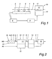
- the in the Fig. 1 Device for determining the redox state of an anode 11 of a high-temperature fuel cell coated with a catalyst material or consisting of a catalyst material has a piezoelectric sensor device 1 in the H 2 and / or CO and / or CH 4 -containing anode gas stream 5 of the fuel cell Resonator 3 is provided with an oxidizing / reducible in the anode gas stream coating 4.
- the surface of the resonator is in flow communication with the anode gas chamber 11 'and is arranged on the outlet side of the high-temperature fuel cell 10 in the illustrated example.
- the cathode of the fuel cell 10 is denoted by 12.
- the sensor device 1 has a second resonator 6, whose surface is provided with a chemically stable, inert coating 7, which shows no redox behavior in the anode gas stream 5 of the high-temperature fuel cell 10.
- a noble metal or an inert oxide layer be applied on the second resonator 6, for example.
- the chemically stable coating 7 and the oxidizable / reducible coating 4 of the resonators 3 and 6 can - as in Fig. 1 shown - be arranged in two areas of a piezoelectric crystal element 2. As a result, both resonators have the same material-dependent parameters, which considerably simplifies signal evaluation.
- the Resonatoranregung and the signal request can preferably be done via radio.
- first resonator 3 embodied as a BAW resonator
- its opposing surfaces can each be provided with an oxidizable / reducible coating 4, whereby a doubling of the signal strength can be achieved with the same mass occupancy.
- the device according to Fig. 1 has a device 8 for measuring at least one change in the resonance behavior (for example, the resonance frequency) of the resonators 3 and 6 of the piezoelectric sensor device 1, wherein the detected measured value is a measure of the redox state of the anode 11 of the high-temperature fuel cell 10.
- the control device 9 different operating parameters of the high-temperature fuel cell 10 can be regulated or controlled.
- Fig. 2 is schematically shown a fuel cell assembly with a fuel cell 10 including a steam reformer 13 for natural gas operation.
- the in Fig. 1 described piezoelectric sensor 1 can be arranged in the anode gas flow in front of the anode 11 of the fuel cell 10 and at the outlet side of the gas stream from the reformer 13 (see point A) and on the acquired measurement data both information about the state of the anode 11 in the anode gas chamber 11 'of Fuel cell 10 as well as the state of the reaction surface 16 in the gas space 13 'of the reformer 13 give.
- the sensor device 1 can be arranged on the inlet side on the reformer 13 (eg in a common supply line for natural gas and water vapor), after the anode 11 (see point B) or also after an optional heat exchanger 14 in front of an afterburner 15 (see point C).
Landscapes
- Life Sciences & Earth Sciences (AREA)
- Chemical & Material Sciences (AREA)
- Engineering & Computer Science (AREA)
- General Chemical & Material Sciences (AREA)
- Electrochemistry (AREA)
- Physics & Mathematics (AREA)
- Chemical Kinetics & Catalysis (AREA)
- Sustainable Energy (AREA)
- Sustainable Development (AREA)
- Manufacturing & Machinery (AREA)
- Analytical Chemistry (AREA)
- Pathology (AREA)
- Immunology (AREA)
- General Physics & Mathematics (AREA)
- General Health & Medical Sciences (AREA)
- Biochemistry (AREA)
- Health & Medical Sciences (AREA)
- Acoustics & Sound (AREA)
- Fuel Cell (AREA)
- Hydrogen, Water And Hydrids (AREA)
Abstract
Description
- Die Erfindung betrifft ein Verfahren und eine Vorrichtung zur Bestimmung des Redoxzustandes einer mit einem Katalysatormaterial beschichteten, oder aus einem Katalysatormaterial bestehenden Anode einer Hochtemperaturbrennstoffzelle oder einer Reaktionsoberfläche eines Reformers sowie eine piezoelektrische Sensoreinrichtung zur Bestimmung des Redoxzustandes einer oxidier-/reduzierbaren Beschichtung.
- Hochtemperaturbrennstoffzellen wie beispielsweise die Festoxidbrennstoffzelle, oder die Schmelzkarbonatbrennstoffzelle müssen für den Betrieb an den Elektroden mit Gasen versorgt werden, d.h. dem Brenngas (H2, CO oder CH4) an der Anode und dem Oxidationsgas (O2 oder Luft) an der Kathode. Die Gasräume müssen dabei gegeneinander abgedichtet sein. Eine unzureichende Dichtung führt zu einer Verringerung der Zellspannung und meist zur Degradation und dem Versagen der Brennstoffzelle.
- Zusätzlich entsteht beispielsweise beim Übertritt von sauerstoff in einen H2-reichen Anodenraum bei Temperaturen unterhalb von 600°C ein hochexplosives Gemisch.
- Als Katalysatormaterial an der Anode wird beispielsweise Nickel (Ni) bzw. Nickel-Cermet verwendet, welches jedoch beim Kontakt mit sauerstoffhältiger Atmosphäre Nickeloxid (NiO) bildet, wodurch die katalytische Aktivität beeinträchtigt wird. Aus diesem Grund muss zur Inbetriebnahme einer Hochtemperaturbrennstoffzelle mit Ni bzw. Ni-Cermet als Anodenmaterial eine sogenannte Reduktionsphase durchlaufen werden, wobei der Anodenraum anfänglich beispielsweise mit Stickstoff gespült und anschließender schrittweiser Erhöhung der Konzentration des Brenngases (beispielsweise Wasserstoffgas), welches als Reduktionsmittel wirkt, durchströmt wird. Während dieser Reduktionsphase wird das NiO zu metallischem Ni reduziert. Umgekehrt ist in manchen Fällen, wie beispielsweise bei Wartungszwecken, eine Oxidation des Anodenmaterials nicht vermeidbar. Die Reduktion und Oxidation der Anode wird auch als "Redox-Cycle" bezeichnet.
- Es ist bekannt derartige "Redox-Cycles" bzw. den Redoxzustand bei Ni/YsZ-Cermet Anoden (YsZ = Yttrium dotiertes Zirkonium) über deren Polarisationszustand, beispielsweise durch Impedanzspektroskopie, zu bestimmen. Diese Untersuchungsmethode wird insbesondere in der Entwicklung von Brennstoffzellen eingesetzt, wobei jedoch nur bei Einzelzellenexperimenten zuverlässig auf die katalytische Aktivität der Anode geschlossen werden kann. Für die laufende Überwachung während des Betriebes einer Hochtemperaturbrennstoffzelle eignet sich dieses Verfahren allerdings nicht.
- Weiters sind aus "Kinetics of Oxidation and Reduction of Ni/YsZ Cermets", 5th European Solid Oxide Fuel Cell Forum, Vol. 1 (2002), pp. 467-474, der Autoren Daniel Fouquet, Axel C. Müller, André Weber und Ellen Ivers-Tiffée kinetische Untersuchungen zur Reduktion und Oxidation von NiO/Ni Pulver und NiO/Ni-YsZ Cermets mit Hilfe von TGA Messungen (Thermogravimetrische Analyse) bekannt geworden. Derartige Messungen können allerdings nicht zur laufenden Überwachung von Hochtemperaturbrennstoffzelle eingesetzt werden.
- Reformer, beispielsweise Dampfreformer zur Erzeugung eines wasserstoffreichen Brenngases für Brennstoffzellen, weisen mit Katalysatormaterialien beschichtete Reaktionsoberflächen auf, an welchen beispielsweise aus den Primärmedien Erdgas und Wasserdampf ein Brenngas gewonnen wird, welches H2 und CO enthält. Weiters werden Reformer eingesetzt, welche mit Methanol als Primärmedium arbeiten, und nach der Gleichung
CH3OH + H2O + Wärme → 3H2 + CO2
ein wasserstoffreiches Brenngas erzeugen. Als Katalysatormaterialien werden unterschiedliche Redoxschichten, beispielsweise Ni/NiO der Nickel-Cermet, eingesetzt. Der Wirkungsgrad sowie die Betriebssicherheit des Reformers ist vom Zustand der Reaktionsoberfläche abhängig. - Aus der
US 6,455.181 B1 ist eine Brennstoffzellenanordnung bekannt, weiche einen Sensor mit einer Membranelektrode aufweist, denen eine Seite mit dem Gaszulauf zur Brennstoffzelle und deren andere Seite mit dem Abgas der Brennstoffzelle in Verbindung steht, wobei beide Seiten der Membranelektrode unterschiedliche Beschichtungen aufweisen. Die unterschiedliche Gaszusammensetzung an beiden Membranseiten, beispielsweise eine unterschiedliche Wasserstoffkonzentration, wird in ein elektrisches Signal umgewandelt, mit welchem Signal der Gasstrom der Brennstoffzelle reguliert werden kann. Es werden somit Unterschiede in der Gaskonzentration zwischen Eingang und Ausgang der Brennstoffzelle gemessen, die Vorrichtung ist allerdings nicht geeignet den Redoxzustand der Anode einer Hochtemperaturbrennstoffzelle bzw. den Redoxzustand der Reaktionsfläche eines Reformers zu bestimmen. - Aus der
US 5,827,947 A ist ein Gassensor bekannt, mit welchem bestimmte Verunreinigungen in einem Fluidstrom gemessen werden können. Dazu ist ein piezoelektrischer Resonator mit einem inerten, porösen Material beschichtet, welches eine Metallverbindung enthält, die auf die zu bestimmenden Gaskomponente, beispielsweise mit einer Redoxreaktion, reagiert. Aus Änderungen des Frequenzverhaltes des Resonators wird auf die Konzentration der Verunreinigung geschlossen. - Aufgabe der Erfindung ist es daher, ein Verfahren bzw. eine Vorrichtung sowie eine Sensoreinrichtung zur Überwachung des Redoxzustandes der Anode einer Hochtemperaturbrennstoffzelle bzw. der katalytischen Reaktionsoberfläche eines Reformers vorzuschlagen, welche im laufenden Betrieb eingesetzt werden können, wobei weiters durch Regelung bzw. Steuerung mindestens eines Betriebsparameters ein optimierter und sicherer Betrieb einer Brennstoffzelle bzw. eines Brennstoffzellensystems samt Reformer gewährleistet sein soll,
- Die Aufgabe wird erfindungsgemäß dadurch gelöst, dass zumindest ein erster Resonator einer piezoelektrischen Sensoreinrichtung mit dem H2- und/oder CO- und/oder CH4-hältigen Anodengasstrom der Hochtemperaturbrennstoffzelle in Kontakt gebracht wird, wobei die Oberfläche des ersten Resonators mit einer im Anodengasstrom oxidier-/reduzierbaren Beschichtung versehen ist, dass zumindest eine Änderung des Resonanzverhaltens, vorzugweise der Resonanzfrequenz, des ersten Resonators gemessen und davon auf den Redoxzustand der Anode der Hochtemperaturbrennstoffzelle geschlossen wird.
- Für die Überwachung der Reaktionsoberfläche eines Reformers wird erfindungsgemäß zumindest ein erster Resonator einer piezoelektrischen Sensoreinrichtung mit dem H2- und/oder CO- und/oder CH4-hältigen Gasstrom des Reformers in Kontakt gebracht, wobei die Oberfläche des ersten Resonators mit einer im Gasstrom oxidier-/reduzierbaren Beschichtung versehen ist, und zumindest eine Änderung des Resonanzverhaltens, vorzugsweise der Resonanzfrequenz, des ersten Resonators gemessen und davon auf den Redoxzustand der Reaktionsfläche des Reformers geschlossen wird.
- Eine erfindungsgemäße Vorrichtung zur Durchführung des Verfahrens ist dadurch gekennzeichnet, dass im Anodengasstrom der Hochtemperaturbrennstoffzelle bzw. im Gasstrom des Reformers, zumindest ein erster Resonator einer piezoelektrischen Sensorseinrichtung angeordnet ist, wobei der erste Resonator mit einer oxidier-/reduzierbaren Beschichtung versehen ist, sowie dass die Vorrichtung eine Einrichtung zur Messung zumindest einer Änderung des Resonanzverhaltens des ersten Resonators aufweist, wobei der erfasste Messwert ein Maß für den Redoxzustand der Anode der Hochtemperaturbrennstoffzelle, bzw. ein Maß für den Redoxzustand der Reaktionsoberfläche des Reformers ist.
- Gemäß einer vorteilhaften Ausführungsvariante besteht die oxidier-/reduzierbare Beschichtung des ersten Resonators aus dem Katalysatormaterial der Anode der Hochtemperaturbrennstoffzelle oder dem Katalysatormaterial der Reaktionsfläche des Reformers.
- Die freie Standard-Bildungsenergie für Oxide, welche von der Temperatur und vom Sauerstoffpartialdruck abhängt, ist aus dem sogenannten Ellingham Diagram für Oxide ablesbar, welches insbesondere bei der Gewinnung von Metallen aus Oxiden eine Rolle spielt. Beispiele für oxidier-/reduzierbare Beschichtungen des ersten Resonators (gegenüber CO- und/oder H2- bzw. CH4-hältigen Gasen) sind: Cu/CuO, Ni/NiO, Pb/PbO, Co/CoO, Ag/AgO, Pd/PdO sowie Nickel-Cermet.
- Für Differenzmessungen ist erfindungsgemäß im Gasstrom zumindest ein zweiter Resonator der piezoelektrischen Sensoreinrichtung angeordnet, wobei der zweite Resonator eine im Gasstrom chemisch stabile Beschichtung aufweist. Dabei wird die Differenzfrequenz zwischen dem ersten und zweiten Resonator der Sensoreinrichtung als Maß für den Redoxzustand der reduzier-/oxidierbaren Schicht herangezogen. Beispiele für chemisch stabile Beschichtungen (gegenüber CO- und/oder H2- bzw. CH4-hältigen Gasen) sind: CaO, MgO, Al2O3, TiO2, SiO2, MnO, V/VO, Cr/CrO, sowie Edelmetalle.
- Erfindungsgemäß ist vorgesehen, dass in Abhängigkeit der gemessenen Änderung des Resonanzverhaltens, vorzugsweise in Abhängigkeit der Resonanzfrequenz, zumindest ein Betriebsparameter der Hochtemperaturbrennstoffzelle oder des Reformers gesteuert bzw. geregelt wird.
- Weitere Betriebsparameter können erfindungsgemäß dadurch gewonnen werden, dass die Resonanzfrequenz bzw. der Resonanzwiderstand eines der beiden Resonatoren, vorzugsweise jenes Resonators mit der chemisch stabilen Beschichtung, gemessen und als Maß für die Temperatur bzw. den Druck im Gasstrom verwendet wird. Aus den am Messort gewonnen Daten über Druck, Temperatur und Redoxzustand kann z.B. mit Hilfe der Druck- und Temperaturdaten im Anodenraum einer Brennstoffzelle der Redoxzustand der Anode ermittelt werden. Beispielsweise kann mit der erfindungsgemäßen Vorrichtung die Brenngaszufuhr bzw. Brenngaszusammensetzung zur Anode und/oder die Temperatur während der Startphase und/oder einer Stopphase gesteuert bzw. geregelt werden.
- Eine erfindungsgemäße piezoelektrische Sensoreinrichtung zur Bestimmung des Redoxzustandes einer oxidier-/reduzierbaren Beschichtung, zeichnet sich dadurch aus, dass die oxidier-/reduzierbare Beschichtung auf der Oberfläche zumindest eines ersten Resonators der Sensoreinrichtung aufgetragen ist, wobei die Resonatoroberfläche in Strömungsverbindung mit dem Anodengasraum einer Hochtemperaturbrennstoffzelle oder dem Gasraum eines Reformers bringbar ist. Bevorzugt ist auf der Oberfläche zumindest eines zweiten Resonators der Sensoreinrichtung eine chemisch stabile Beschichtung aufgetragen, welche im Gasstrom der Hochtemperaturbrennstoffzelle oder des Reformers kein Redoxverhalten zeigt. Die beiden Resonatoren können bevorzugt als BAW- oder SAW-Resonatoren ausgeführt sein.
- Eine bevorzugte erfindungsgemäße Anwendung des piezoelektrischer Sensor besteht beispielsweise darin, einen Sauerstoffübertritt, insbesondere während der kritischen Startphase (z.B. aus dem Kathodenkreis), in den Anodenkreis zu erkennen, wodurch die Einleitung einer Ausschalt- oder Notstop-Prozedur für das Brennstoffzellensystem erfolgen kann.
- Die piezoelektrische Sensoreinrichtung kann eingangsseitig oder auch an der Austrittsseite des Anodengasstroms der Brennstoffzelle angeordnet sein. Die am Austritt der Brennstoffzelle auftretende Gaszusammensetzung bei Normalbetrieb der Brennstoffzelle (z.B.: CH4, H2, CO, CO2, N2 und H2O) ist temperatur- und lastabhängig.
- Gemäß einer Ausführungsvariante kann die piezoelektrische Sensoreinrichtung auch im Anodengasraum der Hochtemperaturbrennstoffzelle oder an der Austrittsseite des Gasstroms aus dem Reformer angeordnet sein.
- Die Erfindung wird im Folgenden anhand von schematischen Zeichnungen näher erläutert. Es zeigen:
- Fig. 1
- eine schematische Darstellung einer erfindungsgemäßen Vorrich- tung zur Bestimmung des Redoxzustandes einer Anode einer Hochtemperaturbrennstoffzelle mit dem erfindungsgemäßen piezo- elektrische Sensor und
- Fig. 2
- eine Ausführungsvariante der Vorrichtung nach
Fig. 1 in einer Brennstoffzellenanordnung mit einem Dampfreformer. - Die in der
Fig. 1 dargestellte Vorrichtung zur Bestimmung des Redoxzustandes einer mit einem Katalysatormaterial beschichteten oder aus einem Katalysatormaterial bestehenden Anode 11 einer Hochtemperaturbrennstoffzelle 10 weist im H2- und/oder CO- und/oder CH4-hältigen Anodengasstrom 5 der Brennstoffzelle eine piezoelektrische Sensoreinrichtung 1 auf, dessen erster Resonator 3 mit einer im Anodengasstrom oxidier-/reduzierbaren Beschichtung 4 versehen ist. Die Oberfläche des Resonators steht dabei in Strömungsverbindung mit dem Anodengasraum 11' und ist im dargestellten Beispiel austrittsseitig der Hochtemperaturbrennstoffzelle 10 angeordnet. Die Kathode der Brennstoffzelle 10 ist mit 12 bezeichnet. - Die Sensoreinrichtung 1 weist einen zweiten Resonator 6 auf, dessen Oberfläche mit einer chemisch stabilen, inerten Beschichtung 7 versehen ist, welche im Anodengasstrom 5 der Hochtemperaturbrennstoffzelle 10 kein Redoxverhalten zeigt. Auf dem zweiten Resonator 6 kann z.B. ein Edelmetall oder eine inerte Oxidschicht aufgetragen sein. Die chemisch stabile Beschichtung 7 und die oxidier/reduzierbare Beschichtung 4 der Resonatoren 3 und 6 können - wie in
Fig. 1 dargestellt - in zwei Bereichen eines piezoelektrischen Kristallelementes 2 angeordnet sein. Beide Resonatoren weisen dadurch die selben materialabhängigen Parameter auf, was die Signalauswertung wesentlich erleichtert. - Bei der Verwendung von SAW-Resonatoren kann die Resonatoranregung und die Signalabfrage bevorzugt über Funk erfolgen.
- Bei einem als BAW-Resonator ausgeführten ersten Resonator 3 können dessen gegenüberliegenden Oberflächen jeweils mit einer oxidier-/reduzierbaren Beschichtung 4 versehen sein, wodurch bei gleicher Massenbelegung eine Verdoppelung der Signalstärke erzielt werden kann.
- Weiters ist es möglich, die Resonanzfrequenz oder den Resonanzwiderstand mit Hilfe des Resonators 6 mit der chemisch stabilen Beschichtung 7 zu messen und als Maß für die Temperatur oder den Druck im Anodengasstrom 5 zu verwenden.
- Die Vorrichtung gemäß
Fig. 1 weist eine Einrichtung 8 zur Messung zumindest einer Änderung des Resonanzverhaltens (beispielsweise der Resonanzfrequenz) der Resonatoren 3 und 6 der piezoelektrischen Sensoreinrichtung 1 auf, wobei der erfasste Messwert ein Maß für den Redoxzustand der Anode 11 der Hochtemperaturbrennstoffzelle 10 ist. Über eine Regeleinrichtung 9 können unterschiedliche Betriebsparameter der Hochtemperaturbrennstoffzelle 10 geregelt bzw. gesteuert werden. - In
Fig. 2 ist schematisch eine Brennstoffzellenanordnung mit einer Brennstoffzelle 10 samt einem Dampfreformer 13 für den Erdgasbetrieb dargestellt. Der inFig. 1 beschriebene piezoelektrische Sensor 1 kann im Anodengasstrom vor der Anode 11 der Brennstoffzelle 10 bzw. an der Austrittsseite des Gasstromes aus dem Reformer 13 (siehe Punkt A) angeordnet sein und über die erfassten Messdaten sowohl Auskunft über den Zustand der Anode 11 im Anodengasraum 11' der Brennstoffzelle 10 als auch über den Zustand der Reaktionsoberfläche 16 im Gasraum 13' des Reformers 13 geben. Weiters kann die Sensoreinrichtung 1 eintrittsseitig am Reformer 13 (z.B. in einer gemeinsamen Zuleitung für Erdgas und Wasserdampf), nach der Anode 11 (siehe Punkt B) oder auch nach einem optionalen Wärmetauscher 14 vor einem Nachverbrenner 15 (siehe Punkt C) angeordnet sein.
Claims (15)
- Verfahren zur Bestimmung des Redoxzustandes einer Anode (11) einer Hochtemperaturbrennstoffzelle (10) oder einer Reaktionsfläche (16) eines Reformers (13), wobei die Anode (11) oder die Reaktionsfläche (16) mit einem Katalysatormaterial beschichtet ist, oder aus einem Katalysatormaterial besteht, dadurch gekennzeichnet, dass zumindest ein erster Resonator (3) einer piezoelektrischen Sensoreinrichtung (1) mit dem H2- und/oder CO- und/oder CH4-hältigen Anodengasstrom (5) der Hochtemperaturbrennstoffzelle (10) oder dem H2- und/oder CO- und/oder CH4-hältigen Gasstrom des Reformers (13) in Kontakt gebracht wird, wobei die Oberfläche des ersten Resonators (3) mit einer im Anodengasstrom oder im Gasstrom des Reformers (13) oxidier-/reduzierbaren Beschichtung (4) versehen ist, dass zumindest eine Änderung des Resonanzverhaltens, vorzugsweise eine Änderung der Resonanzfrequenz, des ersten Resonators (3) gemessen und davon auf den Redoxzustand der Anode (11) der Hochtemperaturbrennstoffzelle (10) oder auf den Redoxzustand der Reaktionsfläche (16) des Reformers (13) geschlossen wird.
- Verfahren nach Anspruch 1, dadurch gekennzeichnet, dass in Abhängigkeit der gemessenen Änderung des Resonanzverhaltens, vorzugsweise in Abhängigkeit der Resonanzfrequenz, ein Betriebsparameter der Hochtemperaturbrennstoffzelle (10) oder des Reformers (13) gesteuert bzw. geregelt wird.
- Verfahren nach Anspruch 1 oder 2, dadurch gekennzeichnet, dass zumindest ein zweiter Resonator (6) der piezoelektrischen Sensoreinrichtung (1) mit dem H2- und/oder CO- und/oder CH4-hältigen Gasstrom in Kontakt gebracht wird, welcher mit einer chemisch stabilen Beschichtung (7) versehen ist, sowie dass die Differenzfrequenz zwischen dem ersten (3) und zweiten Resonator (6) der Sensoreinrichtung (1) als Maß für den Redoxzustand Anode (11) der Hochtemperaturbrennstoffzelle (10) oder der Reaktionsfläche (16) des Reformers (13) herangezogen wird.
- Verfahren nach Anspruch 3, dadurch gekennzeichnet, dass die Resonanzfrequenz eines der beiden Resonatoren (3, 6), vorzugsweise jenes Resonators (6) mit der chemisch stabilen Beschichtung (7), gemessen und als Maß für die Temperatur im Gasstrom verwendet wird.
- Verfahren nach Anspruch 3, dadurch gekennzeichnet, dass der Resonanzwiderstand eines der beiden Resonatoren (3, 6), vorzugsweise jenes Resonators (6) mit der chemisch stabilen Beschichtung, gemessen und als Maß für den Druck im Gasstrom verwendet wird.
- Vorrichtung mit einer Anode (11) einer Hochtemperaturbrennstoffzelle (10) oder einer Reaktionsoberfläche (16) eines Reformers (13), wobei die Anode (11) oder die Reaktionsfläche (16) mit einem Katalysatormaterial beschichtet ist oder aus einem Katalysatormaterial besteht, gekennzeichnet durch eine piezoelektrische Sensorseinrichtung (1) mit zumindest einem ersten Resonator (3), der im Anodengasstrom (5) der Hochtemperaturbrennstoffzelle (10) oder im Gasstrom (5) des Reformers (13) angeordnet ist, wobei der erste Resonator (3) mit einer oxidier/reduzierbaren Beschichtung (4) versehen ist, sowie einer Einrichtung (8) zur Messung zumindest einer Änderung des Resonanzverhaltens des ersten Resonators (3), sodass der erfasste Messwert ein Maß für den Redoxzustand der Anode (11) der Hochtemperaturbrennstoffzelle (10) oder ein Maß für den Redoxzustand der Reaktionsoberfläche (16) des Reformers (13) ist.
- Vorrichtung nach Anspruch 6, dadurch gekennzeichnet, dass die oxidier-/reduzierbare Beschichtung (4) des ersten Resonators (3) aus dem Katalysatormaterial der Anode (11) der Hochtemperaturbrennstoffzelle (1) oder dem Katalysatormaterial der Reaktionsfläche (16) des Reformers (13) besteht.
- Vorrichtung nach Anspruch 6 oder 7, dadurch gekennzeichnet, dass die oxidier-/reduzierbare Beschichtung (4) des ersten Resonators (3) aus Nickel-Cermet, Ni/NiO, Cu/CuO, Pb/PbO, Co/CoO Ag/AgO oder Pd/PdO besteht.
- Vorrichtung nach einem der Ansprüche 6 bis 8, dadurch gekennzeichnet, dass die piezoelektrische Sensoreinrichtung (1) zumindest einen zweiten Resonator (6) aufweist, der im Gasstrom (5) der Hochtemperaturbrennstoffzelle (10) oder im Gasstrom des Reformers (13) angeordnet ist, wobei der zweite Resonator (6) eine im Gasstrom (5) chemisch stabile Beschichtung (7) aufweist.
- Vorrichtung nach Anspruch 9, dadurch gekennzeichnet, dass die chemisch stabile Beschichtung (7) des zweiten Resonators (6) ein Edelmetall oder eine Oxidschicht, beispielsweise SiO2, TiO2, Al2O3, CaO, MgO oder MnO ist.
- Vorrichtung nach Anspruch 6, dadurch gekennzeichnet, dass die piezoelektrische Sensoreinrichtung (1) im Anodengasraum (11') der Hochtemperaturbrennstoffzelle (10) oder an der Austrittsseite des Anodengasstroms (5) angeordnet ist.
- Vorrichtung nach Anspruch 6, dadurch gekennzeichnet, dass die piezoelektrische Sensoreinrichtung (1) an der Eintritts- oder Austrittsseite des Gasstroms in den bzw. aus dem Reformer (13) angeordnet ist.
- Vorrichtung nach einem der Ansprüche 9 bis 12, dadurch gekennzeichnet, dass die chemisch stabile Beschichtung (7) und die oxidier-/reduzierbare Beschichtung (4) auf zwei Bereichen eines piezoelektrischen Kristallelementes (2) aufgetragen sind.
- Vorrichtung nach einem der Ansprüche 9 bis 13, dadurch gekennzeichnet, dass die beiden Resonatoren (3, 6) als BAW- oder SAW-Resonatoren ausgeführt sind.
- Vorrichtung nach einem der Ansprüche 9 bis 13, dadurch gekennzeichnet, dass der erste Resonator (3) als BAW-Resonator ausgeführt ist und an den gegenüberliegenden Oberflächen jeweils oxidier-/reduzierbare Beschichtungen (4) aufweist.
Applications Claiming Priority (3)
| Application Number | Priority Date | Filing Date | Title |
|---|---|---|---|
| AT0044903A AT413767B (de) | 2003-03-20 | 2003-03-20 | Verfahren, vorrichtung und sensor zur bestimmung des redoxzustandes eines katalysatormaterials |
| AT4492003 | 2003-03-20 | ||
| PCT/AT2004/000100 WO2004083838A1 (de) | 2003-03-20 | 2004-03-18 | Verfahren und vorrichtung zur bestimmung des redoxzustandes einer mit einem katalysatormaterial beschichteten reaktionsoberfläche |
Publications (2)
| Publication Number | Publication Date |
|---|---|
| EP1604196A1 EP1604196A1 (de) | 2005-12-14 |
| EP1604196B1 true EP1604196B1 (de) | 2010-11-10 |
Family
ID=32996819
Family Applications (1)
| Application Number | Title | Priority Date | Filing Date |
|---|---|---|---|
| EP04721426A Expired - Lifetime EP1604196B1 (de) | 2003-03-20 | 2004-03-18 | Verfahren und vorrichtung zur bestimmung des redoxzustandes einer mit einem katalysatormaterial beschichteten reaktionsoberfläche |
Country Status (7)
| Country | Link |
|---|---|
| US (1) | US7513157B2 (de) |
| EP (1) | EP1604196B1 (de) |
| CN (1) | CN1761873A (de) |
| AT (2) | AT413767B (de) |
| DE (1) | DE502004011870D1 (de) |
| DK (1) | DK1604196T3 (de) |
| WO (1) | WO2004083838A1 (de) |
Cited By (1)
| Publication number | Priority date | Publication date | Assignee | Title |
|---|---|---|---|---|
| DE102016125399A1 (de) * | 2016-12-22 | 2018-06-28 | Eisenhuth Gmbh & Co. Kg | Energiewandler-Oxidationsmessanlage und Energiewandler-Oxidationsmessverfahren für eine Messung eines Oxidationsverhaltens eines Prüflings |
Families Citing this family (2)
| Publication number | Priority date | Publication date | Assignee | Title |
|---|---|---|---|---|
| CN109327200A (zh) * | 2018-11-27 | 2019-02-12 | 中电科技德清华莹电子有限公司 | 一种声表面波谐振结构滤波器 |
| CN113707906B (zh) * | 2021-08-25 | 2023-03-07 | 中国第一汽车股份有限公司 | 一种燃料电池发动机系统、控制方法及车辆 |
Family Cites Families (14)
| Publication number | Priority date | Publication date | Assignee | Title |
|---|---|---|---|---|
| GB1049742A (en) * | 1963-04-09 | 1966-11-30 | Exxon Research Engineering Co | Improvements in or relating to process and apparatus for gas analysis |
| US3879992A (en) * | 1970-05-12 | 1975-04-29 | California Inst Of Techn | Multiple crystal oscillator measuring apparatus |
| WO1996014573A1 (de) * | 1994-11-07 | 1996-05-17 | Hoechst Aktiengesellschaft | Polymer-sensor |
| US5827947A (en) * | 1997-01-17 | 1998-10-27 | Advanced Technology Materials, Inc. | Piezoelectric sensor for hydride gases, and fluid monitoring apparatus comprising same |
| DE19707814C1 (de) * | 1997-02-27 | 1998-08-20 | Dbb Fuel Cell Engines Gmbh | Brennstoffzellen-Energieerzeugungsanlage |
| US6029500A (en) * | 1998-05-19 | 2000-02-29 | Advanced Technology Materials, Inc. | Piezoelectric quartz crystal hydrogen sensor, and hydrogen sensing method utilizing same |
| JP2000081404A (ja) * | 1998-06-29 | 2000-03-21 | Equos Research Co Ltd | 水素量測定装置 |
| WO2000066266A1 (en) | 1999-05-03 | 2000-11-09 | Cantion A/S | Sensor for microfluid handling system |
| US6222366B1 (en) * | 1999-05-10 | 2001-04-24 | Fisher Controls International, Inc. | High frequency measuring circuit with inherent noise reduction for resonating chemical sensors |
| US6455181B1 (en) * | 2000-03-31 | 2002-09-24 | Plug Power, Inc. | Fuel cell system with sensor |
| US6626026B2 (en) * | 2000-04-07 | 2003-09-30 | Interuniversitair Microelektronica Centrum (Imec) | Acoustic wave based sensor |
| JP2002112390A (ja) * | 2000-10-03 | 2002-04-12 | Nippon Soken Inc | 超音波素子およびガス濃度計測装置 |
| US7111500B2 (en) * | 2002-12-26 | 2006-09-26 | Ulvac Inc. | Analysis method using piezoelectric resonator |
| WO2005001421A2 (en) * | 2003-06-05 | 2005-01-06 | Oakland University | Improved piezoimmunosensor |
-
2003
- 2003-03-20 AT AT0044903A patent/AT413767B/de not_active IP Right Cessation
-
2004
- 2004-03-18 DE DE502004011870T patent/DE502004011870D1/de not_active Expired - Lifetime
- 2004-03-18 WO PCT/AT2004/000100 patent/WO2004083838A1/de not_active Ceased
- 2004-03-18 DK DK04721426.7T patent/DK1604196T3/da active
- 2004-03-18 EP EP04721426A patent/EP1604196B1/de not_active Expired - Lifetime
- 2004-03-18 US US10/549,632 patent/US7513157B2/en not_active Expired - Fee Related
- 2004-03-18 CN CNA2004800074870A patent/CN1761873A/zh active Pending
- 2004-03-18 AT AT04721426T patent/ATE487937T1/de active
Cited By (2)
| Publication number | Priority date | Publication date | Assignee | Title |
|---|---|---|---|---|
| DE102016125399A1 (de) * | 2016-12-22 | 2018-06-28 | Eisenhuth Gmbh & Co. Kg | Energiewandler-Oxidationsmessanlage und Energiewandler-Oxidationsmessverfahren für eine Messung eines Oxidationsverhaltens eines Prüflings |
| DE102016125399B4 (de) | 2016-12-22 | 2024-10-10 | Whitecell Eisenhuth Gmbh & Co. Kg | Energiewandler-Oxidationsmessanlage und Energiewandler-Oxidationsmessverfahren für eine Messung eines Oxidationsverhaltens eines Prüflings |
Also Published As
| Publication number | Publication date |
|---|---|
| ATE487937T1 (de) | 2010-11-15 |
| US20060174705A1 (en) | 2006-08-10 |
| CN1761873A (zh) | 2006-04-19 |
| DK1604196T3 (da) | 2011-02-14 |
| EP1604196A1 (de) | 2005-12-14 |
| AT413767B (de) | 2006-05-15 |
| US7513157B2 (en) | 2009-04-07 |
| ATA4492003A (de) | 2005-09-15 |
| DE502004011870D1 (de) | 2010-12-23 |
| WO2004083838A1 (de) | 2004-09-30 |
Similar Documents
| Publication | Publication Date | Title |
|---|---|---|
| DE10261299B4 (de) | Elektroden, elektrochemische Elemente, Gassensoren und Gasmessverfahren | |
| DE19827927C2 (de) | Gassensor | |
| DE69521451T2 (de) | Verfahren und Vorrichtung zum Messen von einem Gaskomponenten | |
| EP1595301B1 (de) | Schutzschicht für hochtemperaturbelastete substrate sowie verfahren zur herstellung derselben | |
| DE69030098T2 (de) | Gassensor mit festem Elektrolyt und Verfahren zum Messen der Konzentration des zu detektierenden Gases in einer Gasmischung | |
| DE3022282A1 (de) | Vorrichtung zur bestimmung des luft/ brennstoff-verhaeltnisses | |
| EP1287571A1 (de) | Hochtemperaturwerkstoff | |
| DE10247144A1 (de) | Gasdetektorelement und diese enthaltendes Gasdetektorgerät | |
| DE3021745A1 (de) | Vorrichtung zur bestimmung des luft/brennstoff-verhaeltnisses in einem auspuffgas | |
| DE19852247A1 (de) | Stickstoffoxid-Sensor, sowie Stickstoffoxid-Umwandlungsvorrichtung | |
| DE69930175T2 (de) | Kohlenwasserstoffsensor | |
| EP0008430A2 (de) | Mischoxyde für die Elektroden elektrochemischer Hochtemperaturzellen mit Festelektrolyten und Verfahren zu ihrer Herstellung | |
| DE19929625A1 (de) | Stickoxidgassensor | |
| EP2025025B1 (de) | Interkonnektor für einen brennstoff zellenstapel und verfahren zur herstellung | |
| DE10109676A1 (de) | NOx-Gasdetektionsvorrichtung | |
| EP1738428B1 (de) | Elektrisch leitfähiger stahl-keramik-verbund sowie dessen herstellung | |
| EP0931256A1 (de) | Sensorelement zur bestimmung der konzentration oxidierbarer bestandteile in einem gasgemisch | |
| EP1604196B1 (de) | Verfahren und vorrichtung zur bestimmung des redoxzustandes einer mit einem katalysatormaterial beschichteten reaktionsoberfläche | |
| EP3853935A1 (de) | Bauelement mit einer zweilagigen, oxidischen schutzschicht | |
| DE69612531T2 (de) | Elektrochemische Vorrichtung | |
| EP1434985A1 (de) | Sensor zur ermittlung einer kohlenmonoxidkonzentration eines gasgemisches | |
| DE10240918A1 (de) | Gassensor und Verfahren zum Ermitteln einer Gaskonzentration | |
| EP0721583A1 (de) | Elektrochemischer gassensor mit reduzierter querempfindlichkeit | |
| WO2001004981A1 (de) | Oxidationsgeschützte elektrische kontaktierung auf der brenngasseite der hochtemperatur-brennstoffzelle | |
| EP1462796A2 (de) | Gassensor und Verfahren zur Herstellung eines Gassensors |
Legal Events
| Date | Code | Title | Description |
|---|---|---|---|
| PUAI | Public reference made under article 153(3) epc to a published international application that has entered the european phase |
Free format text: ORIGINAL CODE: 0009012 |
|
| 17P | Request for examination filed |
Effective date: 20050910 |
|
| AK | Designated contracting states |
Kind code of ref document: A1 Designated state(s): AT BE BG CH CY CZ DE DK EE ES FI FR GB GR HU IE IT LI LU MC NL PL PT RO SE SI SK TR |
|
| AX | Request for extension of the european patent |
Extension state: AL LT LV MK |
|
| DAX | Request for extension of the european patent (deleted) | ||
| 17Q | First examination report despatched |
Effective date: 20061018 |
|
| GRAP | Despatch of communication of intention to grant a patent |
Free format text: ORIGINAL CODE: EPIDOSNIGR1 |
|
| GRAS | Grant fee paid |
Free format text: ORIGINAL CODE: EPIDOSNIGR3 |
|
| GRAA | (expected) grant |
Free format text: ORIGINAL CODE: 0009210 |
|
| AK | Designated contracting states |
Kind code of ref document: B1 Designated state(s): AT BE BG CH CY CZ DE DK EE ES FI FR GB GR HU IE IT LI LU MC NL PL PT RO SE SI SK TR |
|
| REG | Reference to a national code |
Ref country code: GB Ref legal event code: FG4D Free format text: NOT ENGLISH |
|
| REG | Reference to a national code |
Ref country code: CH Ref legal event code: EP |
|
| REG | Reference to a national code |
Ref country code: IE Ref legal event code: FG4D Free format text: LANGUAGE OF EP DOCUMENT: GERMAN |
|
| REF | Corresponds to: |
Ref document number: 502004011870 Country of ref document: DE Date of ref document: 20101223 Kind code of ref document: P |
|
| REG | Reference to a national code |
Ref country code: DK Ref legal event code: T3 |
|
| REG | Reference to a national code |
Ref country code: NL Ref legal event code: VDEP Effective date: 20101110 |
|
| PG25 | Lapsed in a contracting state [announced via postgrant information from national office to epo] |
Ref country code: PT Free format text: LAPSE BECAUSE OF FAILURE TO SUBMIT A TRANSLATION OF THE DESCRIPTION OR TO PAY THE FEE WITHIN THE PRESCRIBED TIME-LIMIT Effective date: 20110310 Ref country code: FI Free format text: LAPSE BECAUSE OF FAILURE TO SUBMIT A TRANSLATION OF THE DESCRIPTION OR TO PAY THE FEE WITHIN THE PRESCRIBED TIME-LIMIT Effective date: 20101110 Ref country code: SI Free format text: LAPSE BECAUSE OF FAILURE TO SUBMIT A TRANSLATION OF THE DESCRIPTION OR TO PAY THE FEE WITHIN THE PRESCRIBED TIME-LIMIT Effective date: 20101110 Ref country code: BG Free format text: LAPSE BECAUSE OF FAILURE TO SUBMIT A TRANSLATION OF THE DESCRIPTION OR TO PAY THE FEE WITHIN THE PRESCRIBED TIME-LIMIT Effective date: 20110210 Ref country code: NL Free format text: LAPSE BECAUSE OF FAILURE TO SUBMIT A TRANSLATION OF THE DESCRIPTION OR TO PAY THE FEE WITHIN THE PRESCRIBED TIME-LIMIT Effective date: 20101110 Ref country code: CY Free format text: LAPSE BECAUSE OF FAILURE TO SUBMIT A TRANSLATION OF THE DESCRIPTION OR TO PAY THE FEE WITHIN THE PRESCRIBED TIME-LIMIT Effective date: 20101110 Ref country code: SE Free format text: LAPSE BECAUSE OF FAILURE TO SUBMIT A TRANSLATION OF THE DESCRIPTION OR TO PAY THE FEE WITHIN THE PRESCRIBED TIME-LIMIT Effective date: 20101110 |
|
| REG | Reference to a national code |
Ref country code: IE Ref legal event code: FD4D |
|
| PG25 | Lapsed in a contracting state [announced via postgrant information from national office to epo] |
Ref country code: GR Free format text: LAPSE BECAUSE OF FAILURE TO SUBMIT A TRANSLATION OF THE DESCRIPTION OR TO PAY THE FEE WITHIN THE PRESCRIBED TIME-LIMIT Effective date: 20110211 |
|
| PG25 | Lapsed in a contracting state [announced via postgrant information from national office to epo] |
Ref country code: IE Free format text: LAPSE BECAUSE OF FAILURE TO SUBMIT A TRANSLATION OF THE DESCRIPTION OR TO PAY THE FEE WITHIN THE PRESCRIBED TIME-LIMIT Effective date: 20101110 Ref country code: CZ Free format text: LAPSE BECAUSE OF FAILURE TO SUBMIT A TRANSLATION OF THE DESCRIPTION OR TO PAY THE FEE WITHIN THE PRESCRIBED TIME-LIMIT Effective date: 20101110 Ref country code: ES Free format text: LAPSE BECAUSE OF FAILURE TO SUBMIT A TRANSLATION OF THE DESCRIPTION OR TO PAY THE FEE WITHIN THE PRESCRIBED TIME-LIMIT Effective date: 20110221 Ref country code: EE Free format text: LAPSE BECAUSE OF FAILURE TO SUBMIT A TRANSLATION OF THE DESCRIPTION OR TO PAY THE FEE WITHIN THE PRESCRIBED TIME-LIMIT Effective date: 20101110 |
|
| PG25 | Lapsed in a contracting state [announced via postgrant information from national office to epo] |
Ref country code: SK Free format text: LAPSE BECAUSE OF FAILURE TO SUBMIT A TRANSLATION OF THE DESCRIPTION OR TO PAY THE FEE WITHIN THE PRESCRIBED TIME-LIMIT Effective date: 20101110 Ref country code: PL Free format text: LAPSE BECAUSE OF FAILURE TO SUBMIT A TRANSLATION OF THE DESCRIPTION OR TO PAY THE FEE WITHIN THE PRESCRIBED TIME-LIMIT Effective date: 20101110 Ref country code: RO Free format text: LAPSE BECAUSE OF FAILURE TO SUBMIT A TRANSLATION OF THE DESCRIPTION OR TO PAY THE FEE WITHIN THE PRESCRIBED TIME-LIMIT Effective date: 20101110 |
|
| PLBE | No opposition filed within time limit |
Free format text: ORIGINAL CODE: 0009261 |
|
| STAA | Information on the status of an ep patent application or granted ep patent |
Free format text: STATUS: NO OPPOSITION FILED WITHIN TIME LIMIT |
|
| BERE | Be: lapsed |
Owner name: AVL LIST GMBH Effective date: 20110331 |
|
| 26N | No opposition filed |
Effective date: 20110811 |
|
| PG25 | Lapsed in a contracting state [announced via postgrant information from national office to epo] |
Ref country code: MC Free format text: LAPSE BECAUSE OF NON-PAYMENT OF DUE FEES Effective date: 20110331 |
|
| REG | Reference to a national code |
Ref country code: CH Ref legal event code: PL |
|
| REG | Reference to a national code |
Ref country code: DE Ref legal event code: R097 Ref document number: 502004011870 Country of ref document: DE Effective date: 20110811 |
|
| PG25 | Lapsed in a contracting state [announced via postgrant information from national office to epo] |
Ref country code: IT Free format text: LAPSE BECAUSE OF FAILURE TO SUBMIT A TRANSLATION OF THE DESCRIPTION OR TO PAY THE FEE WITHIN THE PRESCRIBED TIME-LIMIT Effective date: 20101110 Ref country code: BE Free format text: LAPSE BECAUSE OF NON-PAYMENT OF DUE FEES Effective date: 20110331 |
|
| PG25 | Lapsed in a contracting state [announced via postgrant information from national office to epo] |
Ref country code: LI Free format text: LAPSE BECAUSE OF NON-PAYMENT OF DUE FEES Effective date: 20110331 Ref country code: CH Free format text: LAPSE BECAUSE OF NON-PAYMENT OF DUE FEES Effective date: 20110331 |
|
| REG | Reference to a national code |
Ref country code: AT Ref legal event code: MM01 Ref document number: 487937 Country of ref document: AT Kind code of ref document: T Effective date: 20110318 |
|
| PG25 | Lapsed in a contracting state [announced via postgrant information from national office to epo] |
Ref country code: AT Free format text: LAPSE BECAUSE OF NON-PAYMENT OF DUE FEES Effective date: 20110318 |
|
| PG25 | Lapsed in a contracting state [announced via postgrant information from national office to epo] |
Ref country code: LU Free format text: LAPSE BECAUSE OF NON-PAYMENT OF DUE FEES Effective date: 20110318 |
|
| PG25 | Lapsed in a contracting state [announced via postgrant information from national office to epo] |
Ref country code: TR Free format text: LAPSE BECAUSE OF FAILURE TO SUBMIT A TRANSLATION OF THE DESCRIPTION OR TO PAY THE FEE WITHIN THE PRESCRIBED TIME-LIMIT Effective date: 20101110 |
|
| PG25 | Lapsed in a contracting state [announced via postgrant information from national office to epo] |
Ref country code: HU Free format text: LAPSE BECAUSE OF FAILURE TO SUBMIT A TRANSLATION OF THE DESCRIPTION OR TO PAY THE FEE WITHIN THE PRESCRIBED TIME-LIMIT Effective date: 20101110 |
|
| PGFP | Annual fee paid to national office [announced via postgrant information from national office to epo] |
Ref country code: DK Payment date: 20140321 Year of fee payment: 11 Ref country code: DE Payment date: 20140328 Year of fee payment: 11 |
|
| PGFP | Annual fee paid to national office [announced via postgrant information from national office to epo] |
Ref country code: GB Payment date: 20140331 Year of fee payment: 11 |
|
| PGFP | Annual fee paid to national office [announced via postgrant information from national office to epo] |
Ref country code: FR Payment date: 20140327 Year of fee payment: 11 |
|
| REG | Reference to a national code |
Ref country code: DE Ref legal event code: R119 Ref document number: 502004011870 Country of ref document: DE |
|
| REG | Reference to a national code |
Ref country code: DK Ref legal event code: EBP Effective date: 20150331 |
|
| GBPC | Gb: european patent ceased through non-payment of renewal fee |
Effective date: 20150318 |
|
| REG | Reference to a national code |
Ref country code: FR Ref legal event code: ST Effective date: 20151130 |
|
| PG25 | Lapsed in a contracting state [announced via postgrant information from national office to epo] |
Ref country code: DE Free format text: LAPSE BECAUSE OF NON-PAYMENT OF DUE FEES Effective date: 20151001 Ref country code: GB Free format text: LAPSE BECAUSE OF NON-PAYMENT OF DUE FEES Effective date: 20150318 |
|
| PG25 | Lapsed in a contracting state [announced via postgrant information from national office to epo] |
Ref country code: FR Free format text: LAPSE BECAUSE OF NON-PAYMENT OF DUE FEES Effective date: 20150331 |
|
| PG25 | Lapsed in a contracting state [announced via postgrant information from national office to epo] |
Ref country code: DK Free format text: LAPSE BECAUSE OF NON-PAYMENT OF DUE FEES Effective date: 20150331 |