EP1603090A2 - Gaming machine - Google Patents
Gaming machine Download PDFInfo
- Publication number
- EP1603090A2 EP1603090A2 EP05012034A EP05012034A EP1603090A2 EP 1603090 A2 EP1603090 A2 EP 1603090A2 EP 05012034 A EP05012034 A EP 05012034A EP 05012034 A EP05012034 A EP 05012034A EP 1603090 A2 EP1603090 A2 EP 1603090A2
- Authority
- EP
- European Patent Office
- Prior art keywords
- display device
- light
- liquid crystal
- disposed
- areas
- Prior art date
- Legal status (The legal status is an assumption and is not a legal conclusion. Google has not performed a legal analysis and makes no representation as to the accuracy of the status listed.)
- Granted
Links
Images




Classifications
-
- G—PHYSICS
- G07—CHECKING-DEVICES
- G07F—COIN-FREED OR LIKE APPARATUS
- G07F17/00—Coin-freed apparatus for hiring articles; Coin-freed facilities or services
- G07F17/32—Coin-freed apparatus for hiring articles; Coin-freed facilities or services for games, toys, sports, or amusements
- G07F17/3202—Hardware aspects of a gaming system, e.g. components, construction, architecture thereof
- G07F17/3204—Player-machine interfaces
- G07F17/3211—Display means
- G07F17/3213—Details of moving display elements, e.g. spinning reels, tumbling members
Definitions
- the present invention relates to a gaming machine equipped with a display device in front of a variable display device that is capable of showing a plurality of symbols.
- a gaming machine which includes a variable display device (First Display Device) that is capable of showing a plurality of symbols, another display device (Second Display Device: Front Display Device) disposed in front of the variable display device, wherein the symbols on the first display device can be seen through the second display device together with the contents shown on the second display device, during the gaming.
- a variable display device First Display Device
- another display device Second Display Device: Front Display Device
- Japanese Patent Application Laid-Open Publication No. 2001-252394 discloses a gaming machine that includes a reel display device and a front display device, which is comprised of a transmission type liquid crystal display device or a transmission EL panel.
- the gaming machine further includes an illumination device disposed on the front display device at a rear side thereof for illuminating the front display device, and a semi-transmission reflection plate. A light, emitted from the illumination device and reflected at the semi-transmission reflection plate, reaches to an area in front of the front display device to be viewable by a player.
- the semi-transmission reflection plate has an area, through which the reel display device can be viewed from a front side of the front display device. Therefore, a portion of the light, emitted from the illumination device, forms a leaked light that transmits through the semi-transmission reflection plate to reach outer peripheries of reels of the reel display device whereby reflections, resulting from the leaded light, appear on the outer peripheries of the reels. For this reason, when viewing the outer peripheries of the reels from the front side of the front display device, such reflections become cumbersome with the resultant issue of a difficulty in viewing the symbols.
- the present invention has been completed to address the above issue and has an object to provide a gaming machine in which second display device is disposed in front of a variable display device (first display device), which is able to show a various symbols, to allow displays of both the display devices to be viewable in an overlapped relationship during a gaming and wherein reflections of lights on outer peripheries of reel are minimized to provide the ease of viewing the symbols on the variable display device.
- first display device variable display device
- a gaming machine comprising: a variable display device variably displaying a plurality of symbols; and a display device disposed in front of the variable display device and having transmission areas for transmitting a surface reflection light reflected at a surface of the variable display device, wherein the variable display device includes a rotary body on which the plurality of symbols are provided and is subjected to surface treatment available to suppress a luster.
- the slot machine 1 is comprised of a variable display device serving (a first display device) for showing a plurality of symbols, and an image display device (a second display device) disposed in front of the variable display device.
- the slot machine 1 is configured to enable a slot game using the plurality of symbols that are variably displayed.
- the slot machine 1 includes an upper display 4 and a lower display 5 that are placed in front of a cabinet 2, respectively.
- the lower display 5 is disposed in a substantially central area between a top and a bottom of the cabinet 2.
- Disposed in an inside of the cabinet 2 in association with the lower display 5 are three mechanical reels 3L, 3C, 3R that rotatably provided along the left side through the right side of the cabinet 2.
- the symbols displayed on the respective reels 3L, 3C, 3R are enabled to be viewable from an outside through symbol display areas 21L, 21C, 21R, which is described below, of the lower display 5.
- the respective reels 3L, 3C, 3R which serve as the variable display devices and will be described below, are configured such that rotating the respective reels 3L, 3C, 3R allow the viewable symbols to be variably displayed through the associated symbol display areas 21L, 21C, 21R.
- the respective reels 3L, 3C, 3R rotate at respective fixed speeds (for instance, 80 rpm).
- a horizontally extending payline (straight line) L1 is disposed so that the payline across the symbol display areas 21L, 21C, 21R, respectively.
- another straight paylines may be disposed in upper and lower areas of the payline L1, respectively, and two oblique paylines may be further disposed.
- the plural paylines it may be structured such that the number of paylinea to be activated varies depending on the amount of inserted coins. That is, the respective paylines are configured to be activated depending on the number of inserted coins and operations of BET switches 9, 10, respectively.
- the payline, which is made effective, is referred to as an activated-line.
- nine symbols can be shown in 21L, 21C, 21R.
- the slot machine 1 is provided with a substantially horizontal base portion 11 in a lower area of the lower display 5.
- a coin insertion slot 6 is provided on the base portion 11 .
- a bill insertion slot 7 is provided on the base portion 11 .
- a spin switch 8 is provided on the base portion 11 .
- a 1-BET switch 9 is provided on the base portion 11 .
- the 1-BET switch 9 is provided for setting a command to allow one coin to be used for one game.
- the maximum BET switch 10 is provided for setting a command to allow the maximum number of coins to be wagered for one game.
- the cabinet 2 has a bottom portion provided with a coin payout opening 13 and a coin receiving portion 14 configured to receive paid-out coins.
- speakers 12L, 12R are provided on both sides of the coin payout opening 13.
- the lower display 5 is comprised of the symbol display areas 21L, 21C, 21R, window frame areas 22L, 22C, 22R, and an effect display area 5a.
- the contents shown on the lower display 5 is changed depend on the combination of the symbols, the state of a stop mode, and a working mode of a liquid display device that will be described below.
- the lower display 5 is provided with other component parts such as a BET number display portion 16, a payout display portion 18 and a credit display portion 19, these component parts are omitted from FIG. 2.
- the upper display 4 has a liquid crystal display device 101 and is configured to show various contents by the liquid crystal display device 101.
- the symbol display areas 21L, 21C, 21R are provided in positions associated with the respective reels 3L, 3C, 3R of the lower display 5 and serves as areas available for the symbols on the respective reels 3L, 3C, 3R, to be viewable. With the symbol display areas 21L, 21C, 21R, the player is able to see the reels 3L, 3C, 3R and the symbols, respectively.
- the window frame areas 22L, 22C, 22R are formed so that surround the associated symbol display areas 21L, 21C, 21R, respectively, and serve as display windows for the symbols on the respective reels 3L, 3C, 3R.
- effect display area 5a is adapted to show various visual effects to enhance an entertaining and provide useful information about the game to the player.
- the upper display 4 is adapted to show a various visual effect based on the operation mode of the liquid crystal display device 101 which will be described below.
- the reels 3L, 3C, 3R is rotatably mounted one by one from left to right to be rotatably mounted, respectively, and have identical structures.
- the reel 3L is described as an example.
- the reel 3L includes a cylindrical frame that is comprised of a pair of annular frames 25, 26, formed in an identical structure, which are connected to each other by means of a plurality of connecting members 27.
- the reel 3L further includes a spoke 28, by which a driving force generated by a stepping motor M1, located at a central area of the cylindrical frames 25, 26, is transferred to the annular frames 25, 26, and a strip-shaped translucent reel sheet 23, shown in FIG. 11, is attached onto outer peripheries of the annular frames 25, 26 to cover the spokes 27.
- a rotor R is comprised of the annular frames 25, 26, the connecting members 27 and the spoke 28.
- a plurality of symbols such as symbols 23a, 23b, 23c, are provided on the reel sheet 23.
- the reel sheet 23 is subjected to surface treatment available to suppress the glazing upon permitting a reflected light to be substantially and uniformly diffused in all directions so as not to cause the reflected light to have directional characteristics.
- Examples of a process for executing surface treatment may include matte (delustering) processing work and embossing work by which a surface is formed with a convexo-concave pattern or embossed pattern.
- the reels 3L, 3C, 3R include circuit boards 24, each for accommodating the LEDs 29, which are disposed in areas rearward of the symbols in a matrix of three pieces in a vertical row and three pieces in a horizontal row (with a sum of nine pieces) to appear in the symbol display areas 21L, 21C, 21R when the rotations of the reels 3L, 3C, 3R stop.
- Each circuit board 24 has three LED receiving portions, juxtaposed along a direction in which each of the reels 3L, 3C, 3R rotates, in each of which a plurality of LEDs 29 are arranged in a matrix pattern as shown in FIG 4.
- the LED receiving portions are illustrated in three rows and the receiving portions bear reference symbols Z1, Z2, Z3, reference symbols Z4, Z5, Z6 and reference symbols Z7, Z8, Z9 for a top row, a central row and a bottom row, respectively, in such an order from the left side.
- the respective LEDs serve as a light emitting device by which white lights are irradiated onto the reel sheets 23, respectively, mounted to the reels 3L, 3C, 3R on the outer peripheries thereof, at respective rear sides.
- the white lights, irradiated from the LEDs 29, transmit through the reel sheets 23 to arrive at front areas (in front of the player) to be illuminated onto the liquid crystal display device 41.
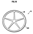
- a sheet member 200 formed with a plurality of convex-lens-like protrusions (omitted in FIG 10), is attached to a surface of the reel sheet 23 as shown in FIG 10.
- the liquid crystal display device 41 is located in front (on a side closer to the player) of the reels 3L, 3C, 3R with a given distance therefrom, thereby forming an image display device.
- the liquid crystal display device 41 is comprised of a protector glass 42, a display plate 43, a liquid crystal panel 44 and a light guide plate 45 and, a reflector film (reflecting member) 46, cold cathode tubes (first light source) 47a, 47b disposed substantially directly below (directly above) the light guide plate 45 to serve as white light sources, lamp holders 49a, 49b, 49g, 49h, and a flexible circuit substrate (not shown) connected to terminal portions of the liquid crystal panel 44 and including a table carrier package (TCP) on which a driver IC (not shown) for the liquid crystal panel 44 is mounted.
- TCP table carrier package
- the protector glass 42 and the display plate 43 have a translucency.
- the protector glass 42 is provided mainly for protecting the liquid crystal display panel 44.
- a predetermined image is provided on the display panel 43.
- the liquid crystal panel 44 is constructed of first transparent substrate plate, such as a glass plate formed with a thin film transistor, and second transparent substrate plate opposed to the first transparent substrate plate, and liquid crystal is sealed between the first and second transparent substrate plate.
- the liquid crystal panel 44 further includes light transmission areas 44L, 44C and 44R, of the present invention, formed in compliance with the symbol display areas 21L, 21C, 21R to transmit a light from a rear surface.
- the liquid crystal panel 44 is configured to have a normally white mode, i.e., a light from the back side thereof is able to transmit towards the front side thereof so that the player can see the reels 3L, 3C, 3R, at the null voltage state.
- the symbols on the respective reels 3L, 3C, 3R can be viewable through the symbol display areas 21L, 21C, 21R to enable the player to perform a game even if the sealed liquid crystal cannot be driven.
- the light transmission areas 44L, 44C, 44R are may be comprised of an opening, respectively.
- the light guide plate 45 has a translucency and is disposed on a rear side of the liquid crystal panel 44 to guide a light emitted from the cold cathode tubes 47a, 47b to the liquid crystal panel 44.
- the light guide plate 45 is formed of a translucent member, such as an acrylic resin having a light guide property, with a thickness of approximately 2.0 cm. As shown in FIG. 6, the light guide plate 45 is formed with transmission openings 45L, 45C, 45R associated with the light transmission areas 44L, 44C, 44R. Further, the light guide plate 45 has a rear side formed with an optical deflection pattern (not shown) and the light transmission openings 45L, 45C, 45R have inner end surfaces 45LX, 45CX, 45RX subjected to light scattering treatment (such as, for instance, a processing to cause a surface to have a refined coarse surface using blast treatment and sand paper).
- light scattering treatment such as, for instance, a processing to cause a surface to have a refined coarse surface using blast treatment and sand paper.
- the incoming light is scattered such that a player is able to view like the inner end surfaces 45LX, 45CX, 45RX are emitting a light. Also, since this light is also irradiated to the respective reels 3L, 3C, 3R, the light is able to serve as an illumination to illuminate the reels 3L, 3C, 3R. Meanwhile, the player sees the symbols on the respective reel 3L, 3C, 3R along a direction indicated by an arrow "F" in FIG. 6.
- a reflection film 46 is provided for reflecting the light, guided to the light guide plate 45, to a front surface of the light plate 45 and made of a white colored polyester film and an aluminum thin film coated with an evaporated silver film.
- the reflection film 46 includes a reflection area 46A and non-reflecdon areas 46BL, 46BC, 46BR.
- the non-reflection areas 46BL, 46BC, 46BR are made of transparent material and perform as a light transmission portion by which an incident light, incoming from the front side, is transmitted without reflection. Further, the non-reflection areas 46BL, 46BC, 46BR are formed in positions associated with the transmission areas 44L, 44C, 44R and placed in front of the symbols in vertical three pieces appearing when the reels 3L, 3C, 3R come to a halt.
- the reflection area 46A serves to reflects the incident light incoming from the front side and serves as an illumination unit for areas mainly associated with the window frame areas 22L, 22C, 22R and the effect display areas 5a among the areas of the liquid crystal panel
- the cold cathode tubes 47a, 47b are located at an upper end and lower end area of the light guide plate 45, respectively, in group of three pieces (a total of 6 pieces) and have both ends supported by lamp holders 49a, 49b, 49g, 49h, respectively, (with the cold cathode tubes 47a, 47b being shown in one piece, respectively, in FIG. 5 for the sake of convenience).
- the cold cathode tubes 47a, 47b emit lights to be guided to the light guide plate 45 and serve as an illumination unit for the areas associated with the window frame areas 22L, 22C, 22R and the effect display areas 5a and emit the lights to the rear side via the transmission openings 45L, 45C, 45R.
- the cold cathode tubes 47a, 47b are disposed in group of three pieces on the upper and lower areas of the guide plate 45, respectively, to increase light intensities of the lights to be guided to the light guide plate 45.
- the number of the cold cathode tubes 47a, 47b may be less than three pieces and in case where the light intensity per one piece has a less value, a larger number of cold cathode tubes 47a, 47b than three pieces may be preferably employed.
- the cold cathode tubes 47a, 47b are disposed in lamp cover 48a, 48b with insides formed with curved reflecting surfaces, respectively.
- the presence of the lamp cover 48a, 48b allows the lights, emitted from the cold cathode tubes 47a, 47b toward an outside of the light guide plate 45, to be guided to the light guide plate 45 without emitting to the outside.
- the liquid crystal display device 101 differs from the liquid crystal display device 41 in that the liquid crystal display device 101 does not include the non-reflection areas 46BL, 46BC, 46BR and the transmission areas 44L, 44C, 44R, a touch panel 56, which is described below, is not disposed on the front side and the reels 3L, 3C, 3R are located on the rear side. And the other structures of the liquid crystal display 101 are similar to those of the liquid crystal display device 41.
- the slot machine 1 is comprised of a control circuit board 71 including a microcomputer 31, a random number generator 35, a sampling circuit 36, a clock pulse generator 37 and a frequency divider 38, a hopper drive circuit 63, a payout complete signal circuit 65, a display driver circuit 67, a sound source 78, a power amplifier 79, an image control circuit and a light emitting driving circuit 91.
- a control circuit board 71 including a microcomputer 31, a random number generator 35, a sampling circuit 36, a clock pulse generator 37 and a frequency divider 38, a hopper drive circuit 63, a payout complete signal circuit 65, a display driver circuit 67, a sound source 78, a power amplifier 79, an image control circuit and a light emitting driving circuit 91.
- the microcomputer 31 includes a CPU (Central Processing Unit) 32, a RAM (Random Access Memory) 33 and a ROM (Read Only Memory) 34.
- the CPU 32 operates in accordance with programs stored in the ROM 34 while sending signals with the other component parts for thereby achieving control operations of the slot machine 1 as a whole.
- the RAM 33 stores therein data and programs, to be used for the CPU 32 to operate, which includes, for instance, random numbers subjected to sampling by the sampling circuit 36 (described below) and temporarily stored after a game has been started, code numbers of the reels 3L, 3C, 3R and symbol numbers.
- the ROM 34 stores therein programs to be executed by the CPU 32, and lasting data.
- the random number generator 35 operates in accordance with a command from the CPU 32 to generate random numbers within a certain definite range.
- the sampling circuit 36 responds to the command from the CPU 32 to extract an arbitrary random number from among the random numbers generated by the random number generator 35, thereafter the extracted random number is inputted to the CPU 32.
- the clock pulse generator 37 generates reference clock pulses, for operating the CPU 32, which are divided by the frequency divider 38 at a fixed frequency to provide a signal that is inputted to the CPU 32.
- the reel drive circuit 50 is comprised of a reel position detecting circuit 51 that detects respective positions of the reels 3L, 3C, 3R, and a motor driving circuit 52 from which drive signals are applied to motors M1, M2, M3 by which the reels 3L, 3C, 3R are rotated, respectively.
- the motors M1, M2, M3 Upon receipt of the drive signals delivered from the motor driving circuit 52, the motors M1, M2, M3 are operated thereby rotating the reels 3L, 3C, 3R.
- a spin switch 8, a 1-BET switch 9, a maximum BET switch 10, an inserted coin sensor 6a and an inserted bill sensor 7a are connected to the control circuit board 71 to receive signals therefrom, respectively.
- the hopper drive circuit 63 drives a hopper 64 in accordance with the control of the CPU 32 to allow the hopper 64 to execute payout operation such that the coins are paid out from a payout opening 13.
- the payout complete signal circuit 65 is applied with coin count data from the associated coin detector 66 and when a coin count value reaches a preset coin count value, the payout completion signal circuit 65 applies the CPU 32 with a signal giving notification that the payout of coins has been completed.
- the coin detector 66 measures a number of coins paid out through the hopper 64, with measured coin count data being inputted to the payout complete signal circuit 65.
- the display driver circuit 67 inputs data to the payout completion signal circuit 65.
- the display driver circuit 67 controls display operations of respective display devices (a BET number display device 16, a payout display device 18 and a credit display device 19).
- the sound source 78 upon the sound source 78 receives a command from the CPU 32, the sound source 78 produces a sound control signal with a sound effect to control the speaker 12L, 12R to outputs the sound effect. That is, upon receipt of the sound control signal with the sound effect from the sound source 78, the power amplifier 79 amplifies the sound effect so that the sound effect is produced from the speakers 12L, 12R.
- the touch panel 56 is provided to cover a surface of the protection glass 42 in front of the lower display 5.
- the image control circuit 81 controls the liquid crystal display devices 41, 101, respectively.
- the image control circuit 81 is comprised of an image control CPU 81a, a working memory (RAM) 81b, a program ROM 81c, an image ROM 81d, a video RAM 81e and a VDP (Video Display Processor) 81f.
- the image control CPU 81a determines images in accordance with an image control program, which is preliminarily stored in the program ROM 81c, for display on the liquid crystal display devices 41, 101 based on parameters preset in the microcomputer 31. Meanwhile, the image control program is provided for liquid crystal display devices 41, 101, respectively.
- the working memory 81b is configured as a temporary storage device that is operative when the image control program is executed by the image control CPU 81a.
- the program ROM 81c stores the image control program and a variety of selection tables.
- the image ROM 81d stores dot data by which the images are formed.
- the video RAM 81e is configured as a temporary storage device that is operative when the image is generated by the VDP 81f.
- the VDP 81f has a control RAM 81g that produces images depending on display contents of the respective liquid crystal display devices 41, 101 determined by the image control CPU 81a, with the respective images being outputted to the liquid crystal display devices 41, 101 for display.
- the light emitting driving circuit 91 outputs drive signals depending on commands from the CPU 32 to turn on the LED 29 and the cathode ray tubes 47a, 47b for emitting lights.
- the slot machine 1 is configured to execute a normal gaming state and a special gaming state.
- a normal gaming state a normal game is played and when the gaming state is shifted to the special gaming state, a bonus game is executed with an advantage for the player.
- FIG. 9 shows a basic operational sequence in parts of main operations to be executed by the slot machine 1 during a period between a start and end of the game. Also, in the FIG.9, a "step” is abbreviated as "S”.
- step 1 With the main operation started as shown in FIG 9, in starting a game, the slot machine 1 performs a start accepting process (step 1) controlled by the CPU 32 and thereafter a sampling process is executed (step 2).
- step 3 normal gaming process is executed with the gaming state remaining in the normal gaming state in step 3 upon which the process proceeds to step 4.
- step 4 upon receipt of a result of the sampling process in step 2, the CPU 32 discriminates whether or not a gaming state change condition is established for the operation to be shifted to the bonus game.
- the process goes to step 5 and if not, the main process is completed.
- the CPU 32 shifts the gaming state to the spatial gaming state by which the bonus game is implemented. Thereafter, the main process is terminated.
- the light emitting driving circuit 91 turns on the cathode ray tubes 47a, 47b in accordance with the command from the CPU 32 in a series of processes described above. Then, lights emitted from the cathode ray tubes 47a, 47b are guided to the light guide plate 45 upon which a portion of the lights is directed toward the rear side through the light guide plate 45 to form leaked lights that transmit through the non-reflection areas 46BL, 46BC, 46BR (whereas the lights arrived at the reflection area 46a is emitted to the front area).
- the light guide plate 45 has the transmission openings 45L, 45C, 45R, the lights pass through the transmission openings 45L, 45C, 45R into the rear side.
- the cathode ray tubes 47a, 47b produce the lights for mainly illuminating the liquid crystal panel 44 at the front side thereof
- the presence of the reflection film 46, placed on the rear side, which is formed with the non-reflection areas 46BL, 46BC, 46BR allows the portion of the lights to pass through the transmission openings 45L, 45C, 45R with the resultant creation of leaked lights.
- the leaked lights arrive at peripheries of the respective reels 3L, 3C, 3R upon which the leaked lights are reflected back on the reel sheets 23, thereby forming a surface reflection light.
- the surface reflection light sequentially transmits through the non-reflection areas 46BL, 46BC, 46BR on the rear side and pass through the transmission openings 45L, 45C, 45R, the transmission areas 44L, 44C, 44R of the liquid crystal display panel 44, the display panel 43 and the protection glass 42 to be incident onto the front side of the liquid crystal display device 41.
- the surface reflection light is made visible for the player and, hence, the player is enabled to view the symbols provided on the outer peripheries of the respective reels 3L, 3C, 3R.
- the slot machine 1 since the slot machine 1 has the respective reels 3L, 3C, 3R inwardly provided with LEDs 29 and the reel sheets 23 has translucency, the presence of light emitted from the LEDs 29 transmits through the reel sheet 23 to reach the front side thereof to be viewed by the player. Therefore, upon lighting up of the LEDs 29, the symbols are illuminated in a lighted-up state, thereby providing a further ease of viewing capability of the symbols.
- the slot machine 1 is configured to allow the symbols on respective reels 3L, 3C, 3R to be clearly viewable, the symbols also can be clearly viewable when the visual contents are displayed on the liquid crystal display device 41.
- the symbols By shown both symbols on the reels 3L, 3C, 3R and the visual contents on the liquid crystal display device 41, a visual rich game can be obtained.
- sheet members 200 are adhered onto the outer peripheries of the respective reels 3L, 3C, 3R and each of the sheet members 200 is formed with a plurality of convex lens-shaped protrusions. Therefore, when the LEDs 29 are lighted up, the player is enabled to view the symbols in three dimensions.
- an example of this kind of sheet member may include a decoration sheet, disclosed in Japanese Patent Laid-Open Publication No. 2003-39583, in which patterns, developed in three dimensions, vary.
- the present invention may have another application such as a pachi-slot machine (a Japanese slot-machine) having the mechanical type reels 3L, 3C, 3R.
- the slot machine 1 is provided with the liquid crystal display device 41, a transparent EL panel may be employed in place of the liquid crystal display device 41.
- the transparent EL panel per se emits a light and, so, the use of such a transparent EL panel enables reduction in a light intensity of a light source to be located on the rear side of the liquid crystal display device 41.
- the slot machine 1 may have a structure (multi-layered structure) wherein another liquid crystal display device is positioned between the front side of the liquid crystal display device, set forth above, and a transparent acrylic plate to allow the two liquid crystal display devices to be disposed in a multi-layered configuration in a direction along a viewing direction of the payer.
- the lower display 5 is enabled to provide a display of an image with a perspective in a three-dimensional appearance.
- the slot machine 1 has been described with reference to a structure wherein the respective three reels are juxtaposed along a row in a horizontal direction, the number of reels is not limited to three. For instance, five or nine reels may be employed.
- the slot machine 1 is the gaming machine of the coin insertion type that needs the coins to be inserted for a start of the game
- the present invention may be applicable to a gaming machine that needs the use of credit such as the coins for the start of the game or the use of pecuniary information stored in a prepaid card.
- the liquid crystal display device (image display device), conformed to the present invention, may be configured in structure as shown in FIG. 12.
- the liquid crystal display device 411 takes the form of a structure that includes cathode ray tubes (second light source) 148a, 148b and a light guide plate 451 of the presently filed embodiment differs from the above-described light guide plate 45 in that no transmission openings 45L, 45C, 45R are provided (single pieces of cathode ray tubes (first light source) 47a, 47b are provided).
- the cathode ray tubes (second light source) 148a, 148b are located in upper and lower areas on the rear side of the reflection film 46 and held by lamp holders 49c, 49d, 49e, 49f to emit lights toward the respective reels 3L, 3C, 3R to illuminate the lights onto the respective reels 3L, 3C, 3R at outer sides thereof.
- the lights, emitted from the cathode ray tubes 148a, 148b reflect at the surfaces of the respective reels 3L, 3C, 3R and are incident on the non-reflection areas 46BL, 46BC, 46BR to cause the lights to reach the liquid crystal panel 44.
- the cathode ray tubes 148a, 148b illuminate the lights onto the symbols on the reel sheets located on the respective reels 3L, 3C, 3R so as to illuminate the lights onto the non-reflection areas 46BL, 46BC, 46BR.
- the lights emitted from the cathode ray tubes 148a, 148b arc illuminated onto the respective reels 3L, 3C, 3R but the reflected lights are reduced.
- the gaming machine equipped with the display device disposed in front of the variable display device that variably display the symbols, no light reflected onto the reel outer peripheries is present and the symbols can be easily viewable in the variable display device.
Landscapes
- Physics & Mathematics (AREA)
- General Physics & Mathematics (AREA)
- Slot Machines And Peripheral Devices (AREA)
- Two-Way Televisions, Distribution Of Moving Picture Or The Like (AREA)
- Telephone Function (AREA)
- Eye Examination Apparatus (AREA)
- Nitrogen And Oxygen Or Sulfur-Condensed Heterocyclic Ring Systems (AREA)
Abstract
Description
Claims (5)
- A gaming machine comprising:wherein the variable display device includes a rotary body (R) on which the plurality of symbols are provided and is subjected to surface treatment available to suppress a luster.a variable display device (3L, 3C, 3R) variably displaying a plurality of symbols; anda display device (41, 411) disposed in front of the variable display device and having transmission areas (44L, 44C, 44R) for transmitting a surface reflection light reflected at a surface of the variable display device;
- The gaming machine of claim 1, wherein
the rotary body of the variable display device includes a light emitting device (29) disposed inside the rotary body; and
a reel sheet (23), subjected to surface treatment available to suppress a luster and having a translucency and the plurality of symbols thereon, which is mounted on an outer periphery of the rotary body. - The gaming machine of claim 2, wherein
the display device further includes:a liquid crystal panel (44) having the transmission areas;a light guide plate (45) disposed on a rear side of the liquid crystal panel and having transmission openings (45L, 45C, 45R) formed in positions corresponding to the transmission areas;a reflecting member (46) disposed on a rear side of the light guide plate and having non-reflection areas (46BL, 46BC, 46BR) disposed in positions corresponding to the transmission openings; anda first light source (47a, 47b) located between the liquid crystal panel and the reflecting member on at least one of upper and lower areas of the light guide plate;wherein a portion of light emitted from the first light source is reflected at a reflection area (46A) formed on a front surface of the reflection member after which the portion of the light transmits through the light guide plate to form a light source for the liquid crystal panel whereby an effect, displayed over the liquid crystal panel, is projected on a display plate, disposed in front of the liquid crystal panel, as a first image; anda portion of the light, emitted from the first light source, passing through the non-reflection areas is illuminated onto a surface of the reel sheet, disposed on the rotary body, after which the light which is illuminated onto the surface of the reel sheet is reflected toward the liquid crystal panel whereby the plurality of symbols on the reel sheet pass through the non-reflection areas, the transmission openings and the transmission areas and is projected on the display device in an overlapped relationship with the first image for display as a second image. - The gaming machine of claim 3, wherein
the transmission openings (45L, 45C, 45R) of the light guide plate have inner end surfaces (45Lx, 45CX, 45RX) that are subjected to light scattering treatment. - The gaming machine of claim 2, wherein
the display device (411) further includes:a liquid crystal panel (44) having the transmission areas are provided;a light guide plate (451) disposed rear side of the liquid crystal panel;a first light source (47a, 47b) disposed in at least one of upper and lower positions of the light guide plate; anda reflection member (46) disposed on a rear side of the light guide plate between the light guide plate and the variable display device and having non-reflection areas (46BL, 46BC, 46BR) disposed in positions corresponding to the transmission openings, wherein the reflection member includes a second light source (148a, 148b) that emits a light toward the rotary body,wherein a portion of light, emitted from the first light source, is reflected at a reflection area (46A), formed on a front surface of the reflection member, after which the portion of the light transmits through the light guide plate to form a light source for the liquid crystal panel whereby an effect, displayed over the liquid crystal panel, is projected on a display plate, disposed in front of the liquid crystal panel, as a first image; anda portion of the light emitted from the second light source is illuminated onto a surface of the reel sheet disposed on the rotary body after which the light which is illuminated onto the surface of the reel is reflected toward the liquid crystal panel to subsequently pass through the non-reflection areas whereby the plurality of symbols, disposed on the reel sheet and serving as a second image, are projected onto areas corresponding to the non-reflection areas on the liquid crystal panels such that the second image is projected onto the display device in an overlapped relationship with the first image for display.
Applications Claiming Priority (2)
| Application Number | Priority Date | Filing Date | Title |
|---|---|---|---|
| JP2004167696A JP2005342342A (en) | 2004-06-04 | 2004-06-04 | Game machine |
| JP2004167696 | 2004-06-04 |
Publications (3)
| Publication Number | Publication Date |
|---|---|
| EP1603090A2 true EP1603090A2 (en) | 2005-12-07 |
| EP1603090A3 EP1603090A3 (en) | 2006-05-24 |
| EP1603090B1 EP1603090B1 (en) | 2008-07-30 |
Family
ID=34937225
Family Applications (1)
| Application Number | Title | Priority Date | Filing Date |
|---|---|---|---|
| EP05012034A Expired - Lifetime EP1603090B1 (en) | 2004-06-04 | 2005-06-03 | Gaming machine |
Country Status (11)
| Country | Link |
|---|---|
| US (1) | US8123609B2 (en) |
| EP (1) | EP1603090B1 (en) |
| JP (1) | JP2005342342A (en) |
| CN (1) | CN100482300C (en) |
| AT (1) | ATE403201T1 (en) |
| AU (1) | AU2005202412B2 (en) |
| DE (1) | DE602005008509D1 (en) |
| EA (1) | EA008394B1 (en) |
| ES (1) | ES2309617T3 (en) |
| PT (1) | PT1603090E (en) |
| ZA (1) | ZA200504528B (en) |
Families Citing this family (40)
| Publication number | Priority date | Publication date | Assignee | Title |
|---|---|---|---|---|
| US6517433B2 (en) | 2001-05-22 | 2003-02-11 | Wms Gaming Inc. | Reel spinning slot machine with superimposed video image |
| US7510475B2 (en) | 2001-05-22 | 2009-03-31 | Wms Gaming, Inc. | Gaming machine with superimposed display image |
| US7708640B2 (en) | 2002-02-15 | 2010-05-04 | Wms Gaming Inc. | Gaming machine having a persistence-of-vision display |
| US9064372B2 (en) | 2002-02-15 | 2015-06-23 | Wms Gaming Inc. | Wagering game with simulated mechanical reels having an overlying image display |
| JP2004166820A (en) | 2002-11-18 | 2004-06-17 | Aruze Corp | Game machine |
| JP2004166963A (en) | 2002-11-20 | 2004-06-17 | Aruze Corp | Gaming machine |
| JP2004166962A (en) | 2002-11-20 | 2004-06-17 | Aruze Corp | Game machine |
| ZA200308997B (en) | 2002-11-20 | 2005-08-31 | Universal Entertainment Corp | Gaming machine and display device therefor |
| US8096867B2 (en) | 2002-11-20 | 2012-01-17 | Universal Entertainment Corporation | Gaming machine and display device with fail-tolerant image displaying |
| US8118674B2 (en) * | 2003-03-27 | 2012-02-21 | Wms Gaming Inc. | Gaming machine having a 3D display |
| US7892094B2 (en) | 2003-05-14 | 2011-02-22 | Universal Entertainment Corporation | Gaming machine with a light guiding plate subjected to a light scattering process and having a light deflection pattern |
| JP2005342342A (en) * | 2004-06-04 | 2005-12-15 | Aruze Corp | Game machine |
| US20090131145A1 (en) | 2005-06-30 | 2009-05-21 | Aoki Dion K | Wagering Game with Overlying Transmissive Display for Providing Enhanced Game Features |
| WO2007078752A2 (en) | 2005-12-19 | 2007-07-12 | Wms Gaming Inc. | Multigame gaming machine with transmissive display |
| WO2008005365A2 (en) | 2006-06-30 | 2008-01-10 | Wms Gaming Inc. | Wagering game with simulated mechanical reels |
| US8403743B2 (en) | 2006-06-30 | 2013-03-26 | Wms Gaming Inc. | Wagering game with simulated mechanical reels |
| JP2008017945A (en) | 2006-07-11 | 2008-01-31 | Aruze Corp | Game machine and game control method |
| US9449454B2 (en) | 2006-11-02 | 2016-09-20 | Bally Gaming, Inc. | Wagering game having bonus-award feature with changing state |
| JP2008178519A (en) | 2007-01-24 | 2008-08-07 | Aruze Corp | Game machine |
| JP2008178520A (en) * | 2007-01-24 | 2008-08-07 | Aruze Corp | Game machine |
| US9460582B2 (en) | 2007-07-11 | 2016-10-04 | Bally Gaming, Inc. | Wagering game having display arrangement formed by an image conduit |
| US8210944B2 (en) | 2007-10-29 | 2012-07-03 | Igt | Gaming system having display device with changeable wheel |
| US8262457B2 (en) | 2007-11-01 | 2012-09-11 | Wms Gaming Inc. | Wagering game apparatus and method to provide a trusted gaming environment |
| US8172666B2 (en) | 2008-04-01 | 2012-05-08 | Aruze Gaming America, Inc. | Slot machine |
| USD602995S1 (en) * | 2008-10-20 | 2009-10-27 | Konami Gaming, Incorporated | Rotatable display unit for a gaming machine |
| KR101291807B1 (en) * | 2010-04-23 | 2013-07-31 | 엘지디스플레이 주식회사 | Hybrid Type Liquid Crystal Display Device |
| US8622825B2 (en) * | 2010-06-22 | 2014-01-07 | Igt | Mechanically rotating wheel with changeable image |
| US8545305B2 (en) * | 2010-06-28 | 2013-10-01 | Wms Gaming Inc. | Devices, systems, and methods for dynamically simulating a component of a wagering game |
| US8203659B2 (en) * | 2010-08-13 | 2012-06-19 | Litemax Electronics Inc. | LCD display and gaming machine combination |
| US8651943B2 (en) * | 2011-06-02 | 2014-02-18 | Universal Entertainment Corporation | Gaming machine |
| US8298081B1 (en) | 2011-06-16 | 2012-10-30 | Igt | Gaming system, gaming device and method for providing multiple display event indicators |
| US8605114B2 (en) | 2012-02-17 | 2013-12-10 | Igt | Gaming system having reduced appearance of parallax artifacts on display devices including multiple display screens |
| US9082256B2 (en) * | 2012-04-17 | 2015-07-14 | Igt | Backlight for video display |
| JP2013230271A (en) * | 2012-04-27 | 2013-11-14 | Universal Entertainment Corp | Gaming machine |
| BE1019941A3 (en) * | 2012-06-05 | 2013-02-05 | Tait Technologies Bvba | DEVICE FOR VIEWING THREE-DIMENSIONAL IMAGES, CREATION OF THREE-DIMENSIONAL IMAGES, AND METHOD FOR CREATING THREE-DIMENSIONAL IMAGES. |
| TWI490829B (en) * | 2013-01-11 | 2015-07-01 | 友達光電股份有限公司 | Display panel and display device |
| TWI522696B (en) * | 2014-05-29 | 2016-02-21 | 友達光電股份有限公司 | Electronic device having transparent display function and display device thereof |
| WO2019138860A1 (en) * | 2018-01-11 | 2019-07-18 | 積水化学工業株式会社 | Game machine and effect producing method for game machine |
| WO2020009092A1 (en) * | 2018-07-04 | 2020-01-09 | 日本精機株式会社 | Head-up display |
| US11127245B2 (en) * | 2018-10-03 | 2021-09-21 | Sg Gaming, Inc. | Compact game display system with virtual depth augmentation |
Family Cites Families (151)
| Publication number | Priority date | Publication date | Assignee | Title |
|---|---|---|---|---|
| US4198147A (en) * | 1976-09-13 | 1980-04-15 | Alasia Alfred Victor | Encoding system |
| US4306768A (en) | 1979-04-13 | 1981-12-22 | Taito America Corporation | Creation of multiplanular images |
| US4562433A (en) | 1980-09-02 | 1985-12-31 | Mcdonnell Douglas Corporation | Fail transparent LCD display |
| EP0060019A1 (en) | 1981-02-06 | 1982-09-15 | Barcrest Limited | Entertainment machines |
| US4454670A (en) * | 1981-03-17 | 1984-06-19 | The Coca-Cola Company | Vending machine display panel with utility module therein |
| US4517558A (en) * | 1982-05-03 | 1985-05-14 | International Game Technology | Three dimensional video screen display effect |
| AU1585083A (en) | 1982-07-06 | 1984-01-12 | Bally Manufacturing Corp. | Combination video-surface projectile game |
| US4568928A (en) * | 1983-05-16 | 1986-02-04 | Mcdonnell Douglas Corporation | Fail transparent electro-luminescent display with backup |
| GB8423632D0 (en) | 1984-09-19 | 1984-10-24 | Jpm Automatic Machines Ltd | Gaming/amusement with-prizes machines |
| JPH0519100Y2 (en) * | 1985-11-15 | 1993-05-20 | ||
| JP2531253B2 (en) | 1988-06-29 | 1996-09-04 | 日本電気株式会社 | Method for removing phenols and aromatic amines from aqueous solution |
| GB8918448D0 (en) * | 1989-08-12 | 1989-09-20 | Bell Fruit Mfg Co Ltd | Gaming and amusement machines |
| GB9104099D0 (en) | 1991-02-27 | 1991-04-17 | Bell Fruit Mfg Co Ltd | Gaming or amusement machines |
| US5283560A (en) * | 1991-06-25 | 1994-02-01 | Digital Equipment Corporation | Computer system and method for displaying images with superimposed partially transparent menus |
| JP3138313B2 (en) * | 1992-02-05 | 2001-02-26 | 株式会社ナムコ | Image synthesis scope, image synthesis device, and game device |
| US5393061A (en) | 1992-12-16 | 1995-02-28 | Spielo Manufacturing Incorporated | Video gaming machine |
| US5580055A (en) | 1993-03-18 | 1996-12-03 | Sigma, Inc. | Amusement device and selectively enhanced display for the same |
| KR0137105B1 (en) * | 1993-06-17 | 1998-04-29 | 모리시다 요이치 | Data transfer circuit, data line driver circuit, amplification circuit, semiconductor integrated circuit and semiconductor memory device |
| AU683095B2 (en) * | 1993-12-27 | 1997-10-30 | Kabushiki Kaisha Ace Denken | Image displaying game machine and image display controlling method |
| JPH07185074A (en) * | 1993-12-27 | 1995-07-25 | Semiconductor Energy Lab Co Ltd | Game machine |
| CA2180114A1 (en) * | 1993-12-28 | 1995-07-06 | Takatoshi Takemoto | Game machine |
| JPH07275432A (en) * | 1994-04-05 | 1995-10-24 | Eagle:Kk | Slot machine |
| JP2865595B2 (en) * | 1995-09-12 | 1999-03-08 | 株式会社三共 | Amusement machine symbol display device, slot machine using the same, and pachinko machine |
| AUPN792996A0 (en) | 1996-02-06 | 1996-02-29 | I.G.T. (Australia) Pty. Limited | A gaming machine |
| AUPN836296A0 (en) * | 1996-02-28 | 1996-03-21 | Aristocrat Leisure Industries Pty Ltd | Roaming wild card |
| US6317128B1 (en) | 1996-04-18 | 2001-11-13 | Silicon Graphics, Inc. | Graphical user interface with anti-interference outlines for enhanced variably-transparent applications |
| JP3189736B2 (en) * | 1996-07-26 | 2001-07-16 | 株式会社デンソー | Composite display |
| AUPO194396A0 (en) * | 1996-08-28 | 1996-09-19 | Aristocrat Leisure Industries Pty Ltd | Slot machine game - hidden object |
| AUPO387796A0 (en) * | 1996-11-27 | 1996-12-19 | Aristocrat Leisure Industries Pty Ltd | Gaming machine |
| US6193606B1 (en) * | 1997-06-30 | 2001-02-27 | Walker Digital, Llc | Electronic gaming device offering a game of knowledge for enhanced payouts |
| JP3451893B2 (en) * | 1997-06-23 | 2003-09-29 | アルゼ株式会社 | Game machine reel device |
| US6135884A (en) * | 1997-08-08 | 2000-10-24 | International Game Technology | Gaming machine having secondary display for providing video content |
| AUPO910297A0 (en) * | 1997-09-10 | 1997-10-02 | Aristocrat Leisure Industries Pty Ltd | Slot machine game - progressive jackpot with decrementing jackpot |
| AUPP008697A0 (en) * | 1997-10-29 | 1997-11-20 | Aristocrat Leisure Industries Pty Ltd | Slot machine - with random line multiplier |
| US5980384A (en) | 1997-12-02 | 1999-11-09 | Barrie; Robert P. | Gaming apparatus and method having an integrated first and second game |
| AUPP206498A0 (en) * | 1998-02-27 | 1998-03-26 | Aristocrat Leisure Industries Pty Ltd | Slot machine game-with randomly designated special symbols |
| US6135885A (en) * | 1998-03-04 | 2000-10-24 | Lermusiaux; Lawrence E. | Electronic football wagering game |
| WO1999046019A1 (en) * | 1998-03-11 | 1999-09-16 | Digideal Corporation | Automated system for playing live casino table games having tabletop changeable playing card displays and play monitoring security features |
| US6190255B1 (en) * | 1998-03-24 | 2001-02-20 | Wms Gaming Inc. | Bonus game for a gaming machine |
| US6027115A (en) * | 1998-03-25 | 2000-02-22 | International Game Technology | Slot machine reels having luminescent display elements |
| US6095921A (en) * | 1998-04-07 | 2000-08-01 | Walker Digital, Llc | Electronic amusement device and method for operating a game offering continuous reels |
| WO1999053454A1 (en) | 1998-04-13 | 1999-10-21 | Game Data, Inc. | Casino game with combination display |
| JPH11299961A (en) * | 1998-04-20 | 1999-11-02 | Daito Giken:Kk | Game board |
| US6036188A (en) * | 1998-05-19 | 2000-03-14 | Williams Electronic Games, Inc. | Amusement game with pinball type playfield and virtual video images |
| AUPP393998A0 (en) | 1998-06-05 | 1998-07-02 | Aristocrat Leisure Industries Pty Ltd | Gaming machine with animated paylines |
| JP3887491B2 (en) * | 1998-06-29 | 2007-02-28 | アビリット株式会社 | Game machine |
| AUPP734198A0 (en) | 1998-11-26 | 1998-12-24 | Aristocrat Leisure Industries Pty Ltd | Player information delivery |
| US6375568B1 (en) * | 1999-01-13 | 2002-04-23 | Interbet Corporation | Interactive gaming system and process |
| GB2349494B (en) | 1999-03-02 | 2003-04-09 | Igt Uk Ltd | Entertainment machines |
| JP2000262738A (en) | 1999-03-18 | 2000-09-26 | Namco Ltd | Game device and information storage medium |
| US6270411B1 (en) * | 1999-09-10 | 2001-08-07 | Wms Gaming Inc. | Gaming machine with animated reel symbols for payoff |
| JP4025463B2 (en) | 1999-06-11 | 2007-12-19 | 山佐株式会社 | Slot machine |
| JP2003507827A (en) * | 1999-08-19 | 2003-02-25 | ディープ ヴィデオ イメイジング リミテッド | How to display a multi-layer screen |
| JP4245742B2 (en) * | 1999-08-23 | 2009-04-02 | アルゼ株式会社 | Game machine |
| EP1079346A3 (en) * | 1999-08-25 | 2001-06-13 | Aruze Corporation | Game machine |
| JP3993347B2 (en) * | 1999-08-27 | 2007-10-17 | 山佐株式会社 | Slot machine |
| US6290600B1 (en) * | 1999-09-08 | 2001-09-18 | Naomi Glasson | Electronic game with moving bonus symbol |
| US6164645A (en) * | 1999-09-14 | 2000-12-26 | Casino Data Systems | Gaming machine |
| US6334612B1 (en) | 1999-11-17 | 2002-01-01 | Wms Gaming Inc. | Ergonomically-designed gaming machine |
| US6302791B1 (en) | 2000-02-09 | 2001-10-16 | Wms Gaming Inc. | Gaming machine with high volatility index |
| JP3936513B2 (en) * | 2000-03-13 | 2007-06-27 | 株式会社デンソー | Game machine |
| US7204753B2 (en) * | 2000-02-28 | 2007-04-17 | Denso Corporation | Pattern display device and game machine including the same |
| US6517432B1 (en) * | 2000-03-21 | 2003-02-11 | Wms Gaming Inc. | Gaming machine with moving symbols on symbol array |
| US6364766B1 (en) * | 2000-08-03 | 2002-04-02 | Wms Gaming Inc. | Gaming machine with sorting feature |
| JP2002113150A (en) | 2000-10-05 | 2002-04-16 | Aruze Corp | Slot machine |
| US6923721B2 (en) * | 2000-12-20 | 2005-08-02 | Sierra Design Group | Apparatus and method for maintaining game state |
| US7510475B2 (en) * | 2001-05-22 | 2009-03-31 | Wms Gaming, Inc. | Gaming machine with superimposed display image |
| US6517433B2 (en) * | 2001-05-22 | 2003-02-11 | Wms Gaming Inc. | Reel spinning slot machine with superimposed video image |
| JP2003079793A (en) * | 2001-09-13 | 2003-03-18 | Denso Corp | Gaming machine |
| US8002624B2 (en) * | 2001-09-27 | 2011-08-23 | Igt | Gaming machine reel having a flexible dynamic display |
| AUPR874201A0 (en) * | 2001-11-08 | 2001-11-29 | Aristocrat Technologies Australia Pty Limited | Gaming machine display |
| JP2003190367A (en) | 2001-12-21 | 2003-07-08 | Konami Co Ltd | False/real image superimposition display, image display control method and program for image display control |
| JP3810321B2 (en) * | 2002-01-10 | 2006-08-16 | コナミ株式会社 | Slot machine |
| JP2003236037A (en) | 2002-02-15 | 2003-08-26 | Daiichi Shokai Co Ltd | Gaming machine |
| US7452276B2 (en) * | 2002-02-15 | 2008-11-18 | Wms Gaming Inc. | Simulation of mechanical reels on a gaming machine |
| JP2003260184A (en) | 2002-03-08 | 2003-09-16 | Sanyo Product Co Ltd | Game machine |
| GB0208533D0 (en) * | 2002-04-13 | 2002-05-22 | Igt Uk Ltd | Entertainment machines |
| JP2004008705A (en) * | 2002-06-11 | 2004-01-15 | Aruze Corp | Gaming machines and display devices for gaming machines |
| JP2004024528A (en) * | 2002-06-25 | 2004-01-29 | Aruze Corp | Gaming machine |
| JP2004081475A (en) * | 2002-06-25 | 2004-03-18 | Aruze Corp | Gaming machine |
| JP2004024495A (en) | 2002-06-25 | 2004-01-29 | Aruze Corp | Gaming machine |
| JP2004024529A (en) * | 2002-06-25 | 2004-01-29 | Aruze Corp | Gaming machine |
| US6976915B2 (en) * | 2002-07-31 | 2005-12-20 | Igt | Gaming device display with simulated halftones |
| US7841944B2 (en) | 2002-08-06 | 2010-11-30 | Igt | Gaming device having a three dimensional display device |
| US20050153775A1 (en) * | 2004-01-12 | 2005-07-14 | Griswold Chauncey W. | Multiple-state display for a gaming apparatus |
| US20070004513A1 (en) * | 2002-08-06 | 2007-01-04 | Igt | Gaming machine with layered displays |
| JP2004073656A (en) * | 2002-08-21 | 2004-03-11 | Aruze Corp | Gaming machine |
| US7465228B2 (en) | 2002-08-21 | 2008-12-16 | Aruze Corp. | Gaming machine having a stop order associated with a prize-winning combination |
| JP3960884B2 (en) | 2002-08-21 | 2007-08-15 | アルゼ株式会社 | Game machine |
| JP4071067B2 (en) | 2002-08-21 | 2008-04-02 | アルゼ株式会社 | Game machine |
| JP2004073651A (en) * | 2002-08-21 | 2004-03-11 | Aruze Corp | Gaming machine |
| US6811273B2 (en) * | 2002-09-26 | 2004-11-02 | Konami Corporation | Illumination unit for reels of slot machine |
| JP2004121534A (en) * | 2002-10-02 | 2004-04-22 | Sanyo Product Co Ltd | Game machine |
| JP4277253B2 (en) * | 2002-10-03 | 2009-06-10 | 株式会社三洋物産 | Game machine |
| JP2004121580A (en) * | 2002-10-03 | 2004-04-22 | Sanyo Product Co Ltd | Game machine |
| JP4269620B2 (en) * | 2002-10-03 | 2009-05-27 | 株式会社三洋物産 | Game machine |
| JP2004121579A (en) * | 2002-10-03 | 2004-04-22 | Sanyo Product Co Ltd | Game machine |
| US20040166925A1 (en) * | 2002-11-15 | 2004-08-26 | Kazuki Emori | Gaming machine |
| JP2004166820A (en) * | 2002-11-18 | 2004-06-17 | Aruze Corp | Game machine |
| JP4081354B2 (en) * | 2002-11-18 | 2008-04-23 | アルゼ株式会社 | Game machine |
| US20040209666A1 (en) * | 2002-11-19 | 2004-10-21 | Hirohisa Tashiro | Gaming machine |
| US20040209670A1 (en) * | 2002-11-19 | 2004-10-21 | Takanobu Adachi | Gaming machine |
| JP2004166880A (en) * | 2002-11-19 | 2004-06-17 | Aruze Corp | Gaming machine |
| JP2004166879A (en) * | 2002-11-19 | 2004-06-17 | Aruze Corp | Gaming machine |
| US7404766B2 (en) * | 2002-11-19 | 2008-07-29 | Aruze Corp. | Gaming machine |
| US20050032571A1 (en) * | 2002-11-19 | 2005-02-10 | Masaaki Asonuma | Gaming machine |
| JP2004166959A (en) | 2002-11-20 | 2004-06-17 | Aruze Corp | Gaming machine |
| JP2004166961A (en) * | 2002-11-20 | 2004-06-17 | Aruze Corp | Gaming machine |
| US7329181B2 (en) * | 2002-11-20 | 2008-02-12 | Aruze Corporation | Gaming machine with multilayered liquid crystal display for displaying images based on a priority order |
| JP2004166962A (en) | 2002-11-20 | 2004-06-17 | Aruze Corp | Game machine |
| JP2004166963A (en) * | 2002-11-20 | 2004-06-17 | Aruze Corp | Gaming machine |
| US7322884B2 (en) | 2002-11-20 | 2008-01-29 | Aruze Corporation | Gaming machine having a variable display |
| JP2004166964A (en) * | 2002-11-20 | 2004-06-17 | Aruze Corp | Gaming machine |
| US20050187003A1 (en) * | 2002-11-20 | 2005-08-25 | Takanobu Adachi | Gaming machine |
| JP3902132B2 (en) * | 2002-12-27 | 2007-04-04 | アルゼ株式会社 | Game machine |
| JP2004242879A (en) | 2003-02-13 | 2004-09-02 | Aruze Corp | Gaming machine |
| US20040214637A1 (en) | 2003-03-03 | 2004-10-28 | Nobuyuki Nonaka | Gaming machine |
| US7316762B2 (en) | 2003-04-11 | 2008-01-08 | Curtiss-Wright Flow Control Corporation | Dynamic flange seal and sealing system |
| US20040224758A1 (en) | 2003-04-30 | 2004-11-11 | Kazuo Okada | Gaming machine |
| US6937298B2 (en) * | 2003-05-14 | 2005-08-30 | Aruze Corp. | Gaming machine having a protective member covering drive unit and at least a portion of the light emission means |
| US7892094B2 (en) | 2003-05-14 | 2011-02-22 | Universal Entertainment Corporation | Gaming machine with a light guiding plate subjected to a light scattering process and having a light deflection pattern |
| US7219893B2 (en) * | 2003-05-14 | 2007-05-22 | Aruze Corporation | Gaming machine |
| US7316395B1 (en) * | 2003-05-23 | 2008-01-08 | Bally Gaming, Inc. | Enhanced reel strip and method for assembling same |
| US20040266515A1 (en) | 2003-06-24 | 2004-12-30 | Michael Gauselmann | Gaming machine with reel strips having an organic light emitting diode display |
| JP2005013356A (en) | 2003-06-24 | 2005-01-20 | Aruze Corp | Game machine |
| JP2005013353A (en) * | 2003-06-24 | 2005-01-20 | Aruze Corp | Game machine |
| US7165323B2 (en) * | 2003-07-03 | 2007-01-23 | Donnelly Corporation | Method of manufacturing a touch screen |
| US20050049030A1 (en) * | 2003-07-18 | 2005-03-03 | Motoaki Tachikawa | Gaming machine with display device for variably displaying symbols thereon and capable of changing number or shapes of symbols under predetermined condition |
| JP2005052636A (en) * | 2003-07-22 | 2005-03-03 | Aruze Corp | Game machine |
| JP2005073821A (en) * | 2003-08-29 | 2005-03-24 | Aruze Corp | Game machine |
| JP2005081015A (en) * | 2003-09-10 | 2005-03-31 | Aruze Corp | Game machine |
| US7309284B2 (en) * | 2004-01-12 | 2007-12-18 | Igt | Method for using a light valve to reduce the visibility of an object within a gaming apparatus |
| US8388432B2 (en) * | 2004-01-12 | 2013-03-05 | Igt | Bi-stable downloadable reel strips |
| JP2005204811A (en) * | 2004-01-21 | 2005-08-04 | Aruze Corp | Game machine |
| JP2005211139A (en) * | 2004-01-27 | 2005-08-11 | Aruze Corp | Game machine |
| JP2005230464A (en) * | 2004-02-23 | 2005-09-02 | Aruze Corp | Slot machine, slot machine control method, and slot machine control program |
| JP2005237898A (en) * | 2004-02-27 | 2005-09-08 | Aruze Corp | Game machine |
| JP2005237896A (en) * | 2004-02-27 | 2005-09-08 | Aruze Corp | Game machine |
| JP2005342344A (en) * | 2004-06-04 | 2005-12-15 | Aruze Corp | Game machine |
| JP2005342342A (en) * | 2004-06-04 | 2005-12-15 | Aruze Corp | Game machine |
| JP2005342343A (en) * | 2004-06-04 | 2005-12-15 | Aruze Corp | Game machine |
| US20060014580A1 (en) * | 2004-07-19 | 2006-01-19 | Nate Hawthorn | Method for providing gaming and a gaming device with electronically modifiable electro-mechanical reel displays |
| WO2006028699A2 (en) * | 2004-09-01 | 2006-03-16 | Wms Gaming Inc. | Gaming machine having electrophoretic displays and method thereof |
| AU2005289527B2 (en) | 2004-09-28 | 2009-06-18 | Wms Gaming Inc. | Transmissive LCD display system for gaming machine |
| US8616969B2 (en) * | 2004-11-02 | 2013-12-31 | Wms Gaming Inc. | Gaming machine with LED display that is an integral part of game play |
| US7166029B2 (en) * | 2004-11-10 | 2007-01-23 | Multimedia Games, Inc. | Curved surface display for a gaming machine |
| US20060281530A1 (en) | 2005-04-08 | 2006-12-14 | Ac Coin And Slot Service Company | Gaming device with organic light emitting diodes and method of use |
| US7594852B2 (en) | 2005-05-04 | 2009-09-29 | Wms Gaming Inc. | Gaming machine with interchangeable reel display arrangement |
| US20080188293A1 (en) | 2005-05-18 | 2008-08-07 | Rasmussen James M | Wagering Game Machine with Transmissive Lcd Lighting |
| US20080182652A1 (en) | 2005-07-15 | 2008-07-31 | Rasmussen James M | Wagering Game Machine with Transmissive Lcd Object Blocking |
| US20070149281A1 (en) * | 2005-09-02 | 2007-06-28 | Igt | Virtual movable mechanical display device |
-
2004
- 2004-06-04 JP JP2004167696A patent/JP2005342342A/en active Pending
-
2005
- 2005-06-02 CN CNB2005100735441A patent/CN100482300C/en not_active Expired - Fee Related
- 2005-06-02 ZA ZA200504528A patent/ZA200504528B/en unknown
- 2005-06-03 AT AT05012034T patent/ATE403201T1/en active
- 2005-06-03 AU AU2005202412A patent/AU2005202412B2/en not_active Ceased
- 2005-06-03 EA EA200500771A patent/EA008394B1/en not_active IP Right Cessation
- 2005-06-03 EP EP05012034A patent/EP1603090B1/en not_active Expired - Lifetime
- 2005-06-03 US US11/144,000 patent/US8123609B2/en not_active Expired - Fee Related
- 2005-06-03 DE DE602005008509T patent/DE602005008509D1/en not_active Expired - Lifetime
- 2005-06-03 ES ES05012034T patent/ES2309617T3/en not_active Expired - Lifetime
- 2005-06-03 PT PT05012034T patent/PT1603090E/en unknown
Also Published As
| Publication number | Publication date |
|---|---|
| AU2005202412A1 (en) | 2005-12-22 |
| CN100482300C (en) | 2009-04-29 |
| EA200500771A1 (en) | 2005-12-29 |
| ZA200504528B (en) | 2006-04-26 |
| AU2005202412B2 (en) | 2012-02-23 |
| EP1603090B1 (en) | 2008-07-30 |
| JP2005342342A (en) | 2005-12-15 |
| US8123609B2 (en) | 2012-02-28 |
| EA008394B1 (en) | 2007-04-27 |
| DE602005008509D1 (en) | 2008-09-11 |
| US20050282617A1 (en) | 2005-12-22 |
| ES2309617T3 (en) | 2008-12-16 |
| CN1706520A (en) | 2005-12-14 |
| ATE403201T1 (en) | 2008-08-15 |
| EP1603090A3 (en) | 2006-05-24 |
| PT1603090E (en) | 2008-09-24 |
Similar Documents
| Publication | Publication Date | Title |
|---|---|---|
| EP1603090B1 (en) | Gaming machine | |
| EP1603091B1 (en) | Gaming machine | |
| US8337286B2 (en) | Gaming machine with image display assistance feature | |
| EP1603092B1 (en) | Gaming machine | |
| JP4081354B2 (en) | Game machine | |
| EP1571626B1 (en) | Gaming machine | |
| JP5759951B2 (en) | Game machine | |
| JP5411427B2 (en) | Game machine | |
| CN100542641C (en) | Game machine | |
| EP1571616B1 (en) | Gaming machine with display illumination means | |
| EP1571623A1 (en) | Gaming machine | |
| AU2004200819B2 (en) | Gaming Machine | |
| AU2004200817B2 (en) | Gaming Machine | |
| AU2004200904B2 (en) | Gaming machine | |
| JP2005312685A (en) | Game machine | |
| EP1571615A1 (en) | Gaming machine | |
| JP2005087384A (en) | Game machine | |
| JP2008104688A (en) | Game machine | |
| JP2008005946A (en) | Game machine | |
| JP2017221728A (en) | Game machine | |
| JP2005073754A (en) | Game machine |
Legal Events
| Date | Code | Title | Description |
|---|---|---|---|
| PUAI | Public reference made under article 153(3) epc to a published international application that has entered the european phase |
Free format text: ORIGINAL CODE: 0009012 |
|
| AK | Designated contracting states |
Kind code of ref document: A2 Designated state(s): AT BE BG CH CY CZ DE DK EE ES FI FR GB GR HU IE IS IT LI LT LU MC NL PL PT RO SE SI SK TR |
|
| AX | Request for extension of the european patent |
Extension state: AL BA HR LV MK YU |
|
| PUAL | Search report despatched |
Free format text: ORIGINAL CODE: 0009013 |
|
| AK | Designated contracting states |
Kind code of ref document: A3 Designated state(s): AT BE BG CH CY CZ DE DK EE ES FI FR GB GR HU IE IS IT LI LT LU MC NL PL PT RO SE SI SK TR |
|
| AX | Request for extension of the european patent |
Extension state: AL BA HR LV MK YU |
|
| 17P | Request for examination filed |
Effective date: 20061024 |
|
| 17Q | First examination report despatched |
Effective date: 20061127 |
|
| AKX | Designation fees paid |
Designated state(s): AT BE BG CH CY CZ DE DK EE ES FI FR GB GR HU IE IS IT LI LT LU MC NL PL PT RO SE SI SK TR |
|
| GRAP | Despatch of communication of intention to grant a patent |
Free format text: ORIGINAL CODE: EPIDOSNIGR1 |
|
| GRAS | Grant fee paid |
Free format text: ORIGINAL CODE: EPIDOSNIGR3 |
|
| GRAA | (expected) grant |
Free format text: ORIGINAL CODE: 0009210 |
|
| AK | Designated contracting states |
Kind code of ref document: B1 Designated state(s): AT BE BG CH CY CZ DE DK EE ES FI FR GB GR HU IE IS IT LI LT LU MC NL PL PT RO SE SI SK TR |
|
| REG | Reference to a national code |
Ref country code: GB Ref legal event code: FG4D |
|
| REG | Reference to a national code |
Ref country code: CH Ref legal event code: EP |
|
| REF | Corresponds to: |
Ref document number: 602005008509 Country of ref document: DE Date of ref document: 20080911 Kind code of ref document: P |
|
| REG | Reference to a national code |
Ref country code: IE Ref legal event code: FG4D |
|
| REG | Reference to a national code |
Ref country code: PT Ref legal event code: SC4A Free format text: AVAILABILITY OF NATIONAL TRANSLATION Effective date: 20080915 |
|
| REG | Reference to a national code |
Ref country code: ES Ref legal event code: FG2A Ref document number: 2309617 Country of ref document: ES Kind code of ref document: T3 |
|
| PG25 | Lapsed in a contracting state [announced via postgrant information from national office to epo] |
Ref country code: IS Free format text: LAPSE BECAUSE OF FAILURE TO SUBMIT A TRANSLATION OF THE DESCRIPTION OR TO PAY THE FEE WITHIN THE PRESCRIBED TIME-LIMIT Effective date: 20081130 Ref country code: LT Free format text: LAPSE BECAUSE OF FAILURE TO SUBMIT A TRANSLATION OF THE DESCRIPTION OR TO PAY THE FEE WITHIN THE PRESCRIBED TIME-LIMIT Effective date: 20080730 Ref country code: NL Free format text: LAPSE BECAUSE OF FAILURE TO SUBMIT A TRANSLATION OF THE DESCRIPTION OR TO PAY THE FEE WITHIN THE PRESCRIBED TIME-LIMIT Effective date: 20080730 |
|
| PG25 | Lapsed in a contracting state [announced via postgrant information from national office to epo] |
Ref country code: FI Free format text: LAPSE BECAUSE OF FAILURE TO SUBMIT A TRANSLATION OF THE DESCRIPTION OR TO PAY THE FEE WITHIN THE PRESCRIBED TIME-LIMIT Effective date: 20080730 Ref country code: BG Free format text: LAPSE BECAUSE OF FAILURE TO SUBMIT A TRANSLATION OF THE DESCRIPTION OR TO PAY THE FEE WITHIN THE PRESCRIBED TIME-LIMIT Effective date: 20081030 Ref country code: SI Free format text: LAPSE BECAUSE OF FAILURE TO SUBMIT A TRANSLATION OF THE DESCRIPTION OR TO PAY THE FEE WITHIN THE PRESCRIBED TIME-LIMIT Effective date: 20080730 |
|
| PG25 | Lapsed in a contracting state [announced via postgrant information from national office to epo] |
Ref country code: BE Free format text: LAPSE BECAUSE OF FAILURE TO SUBMIT A TRANSLATION OF THE DESCRIPTION OR TO PAY THE FEE WITHIN THE PRESCRIBED TIME-LIMIT Effective date: 20080730 |
|
| PG25 | Lapsed in a contracting state [announced via postgrant information from national office to epo] |
Ref country code: DK Free format text: LAPSE BECAUSE OF FAILURE TO SUBMIT A TRANSLATION OF THE DESCRIPTION OR TO PAY THE FEE WITHIN THE PRESCRIBED TIME-LIMIT Effective date: 20080730 Ref country code: EE Free format text: LAPSE BECAUSE OF FAILURE TO SUBMIT A TRANSLATION OF THE DESCRIPTION OR TO PAY THE FEE WITHIN THE PRESCRIBED TIME-LIMIT Effective date: 20080730 |
|
| PG25 | Lapsed in a contracting state [announced via postgrant information from national office to epo] |
Ref country code: SK Free format text: LAPSE BECAUSE OF FAILURE TO SUBMIT A TRANSLATION OF THE DESCRIPTION OR TO PAY THE FEE WITHIN THE PRESCRIBED TIME-LIMIT Effective date: 20080730 Ref country code: RO Free format text: LAPSE BECAUSE OF FAILURE TO SUBMIT A TRANSLATION OF THE DESCRIPTION OR TO PAY THE FEE WITHIN THE PRESCRIBED TIME-LIMIT Effective date: 20080730 Ref country code: CZ Free format text: LAPSE BECAUSE OF FAILURE TO SUBMIT A TRANSLATION OF THE DESCRIPTION OR TO PAY THE FEE WITHIN THE PRESCRIBED TIME-LIMIT Effective date: 20080730 |
|
| PLBE | No opposition filed within time limit |
Free format text: ORIGINAL CODE: 0009261 |
|
| STAA | Information on the status of an ep patent application or granted ep patent |
Free format text: STATUS: NO OPPOSITION FILED WITHIN TIME LIMIT |
|
| 26N | No opposition filed |
Effective date: 20090506 |
|
| PG25 | Lapsed in a contracting state [announced via postgrant information from national office to epo] |
Ref country code: SE Free format text: LAPSE BECAUSE OF FAILURE TO SUBMIT A TRANSLATION OF THE DESCRIPTION OR TO PAY THE FEE WITHIN THE PRESCRIBED TIME-LIMIT Effective date: 20081030 Ref country code: MC Free format text: LAPSE BECAUSE OF NON-PAYMENT OF DUE FEES Effective date: 20090630 |
|
| REG | Reference to a national code |
Ref country code: CH Ref legal event code: PL |
|
| REG | Reference to a national code |
Ref country code: IE Ref legal event code: MM4A |
|
| PG25 | Lapsed in a contracting state [announced via postgrant information from national office to epo] |
Ref country code: LI Free format text: LAPSE BECAUSE OF NON-PAYMENT OF DUE FEES Effective date: 20090630 Ref country code: IE Free format text: LAPSE BECAUSE OF NON-PAYMENT OF DUE FEES Effective date: 20090603 Ref country code: CH Free format text: LAPSE BECAUSE OF NON-PAYMENT OF DUE FEES Effective date: 20090630 |
|
| PG25 | Lapsed in a contracting state [announced via postgrant information from national office to epo] |
Ref country code: PL Free format text: LAPSE BECAUSE OF FAILURE TO SUBMIT A TRANSLATION OF THE DESCRIPTION OR TO PAY THE FEE WITHIN THE PRESCRIBED TIME-LIMIT Effective date: 20080730 |
|
| PG25 | Lapsed in a contracting state [announced via postgrant information from national office to epo] |
Ref country code: GR Free format text: LAPSE BECAUSE OF FAILURE TO SUBMIT A TRANSLATION OF THE DESCRIPTION OR TO PAY THE FEE WITHIN THE PRESCRIBED TIME-LIMIT Effective date: 20081031 |
|
| PG25 | Lapsed in a contracting state [announced via postgrant information from national office to epo] |
Ref country code: LU Free format text: LAPSE BECAUSE OF NON-PAYMENT OF DUE FEES Effective date: 20090603 |
|
| PG25 | Lapsed in a contracting state [announced via postgrant information from national office to epo] |
Ref country code: HU Free format text: LAPSE BECAUSE OF FAILURE TO SUBMIT A TRANSLATION OF THE DESCRIPTION OR TO PAY THE FEE WITHIN THE PRESCRIBED TIME-LIMIT Effective date: 20090131 |
|
| PG25 | Lapsed in a contracting state [announced via postgrant information from national office to epo] |
Ref country code: TR Free format text: LAPSE BECAUSE OF FAILURE TO SUBMIT A TRANSLATION OF THE DESCRIPTION OR TO PAY THE FEE WITHIN THE PRESCRIBED TIME-LIMIT Effective date: 20080730 |
|
| PG25 | Lapsed in a contracting state [announced via postgrant information from national office to epo] |
Ref country code: CY Free format text: LAPSE BECAUSE OF FAILURE TO SUBMIT A TRANSLATION OF THE DESCRIPTION OR TO PAY THE FEE WITHIN THE PRESCRIBED TIME-LIMIT Effective date: 20080730 |
|
| REG | Reference to a national code |
Ref country code: ES Ref legal event code: PC2A Owner name: UNIVERSAL ENTERTAINMENT CORPORATION Effective date: 20120207 |
|
| REG | Reference to a national code |
Ref country code: DE Ref legal event code: R082 Ref document number: 602005008509 Country of ref document: DE Representative=s name: GRUENECKER, KINKELDEY, STOCKMAIR & SCHWANHAEUS, DE |
|
| REG | Reference to a national code |
Ref country code: DE Ref legal event code: R081 Ref document number: 602005008509 Country of ref document: DE Owner name: UNIVERSAL ENTERTAINMENT CORP., JP Free format text: FORMER OWNER: ARUZE CORP., TOKIO/TOKYO, JP Effective date: 20120423 Ref country code: DE Ref legal event code: R082 Ref document number: 602005008509 Country of ref document: DE Representative=s name: GRUENECKER, KINKELDEY, STOCKMAIR & SCHWANHAEUS, DE Effective date: 20120423 Ref country code: DE Ref legal event code: R082 Ref document number: 602005008509 Country of ref document: DE Representative=s name: GRUENECKER PATENT- UND RECHTSANWAELTE PARTG MB, DE Effective date: 20120423 |
|
| REG | Reference to a national code |
Ref country code: AT Ref legal event code: HC Ref document number: 403201 Country of ref document: AT Kind code of ref document: T Owner name: UNIVERSAL ENTERTAINMENT CORPORATION, JP Effective date: 20120427 |
|
| REG | Reference to a national code |
Ref country code: FR Ref legal event code: PLFP Year of fee payment: 11 |
|
| PGFP | Annual fee paid to national office [announced via postgrant information from national office to epo] |
Ref country code: GB Payment date: 20150618 Year of fee payment: 11 Ref country code: PT Payment date: 20150530 Year of fee payment: 11 Ref country code: DE Payment date: 20150619 Year of fee payment: 11 Ref country code: ES Payment date: 20150626 Year of fee payment: 11 |
|
| PGFP | Annual fee paid to national office [announced via postgrant information from national office to epo] |
Ref country code: AT Payment date: 20150619 Year of fee payment: 11 Ref country code: IT Payment date: 20150622 Year of fee payment: 11 Ref country code: FR Payment date: 20150619 Year of fee payment: 11 |
|
| REG | Reference to a national code |
Ref country code: DE Ref legal event code: R119 Ref document number: 602005008509 Country of ref document: DE |
|
| REG | Reference to a national code |
Ref country code: AT Ref legal event code: MM01 Ref document number: 403201 Country of ref document: AT Kind code of ref document: T Effective date: 20160603 |
|
| PG25 | Lapsed in a contracting state [announced via postgrant information from national office to epo] |
Ref country code: PT Free format text: LAPSE BECAUSE OF NON-PAYMENT OF DUE FEES Effective date: 20161205 |
|
| GBPC | Gb: european patent ceased through non-payment of renewal fee |
Effective date: 20160603 |
|
| REG | Reference to a national code |
Ref country code: FR Ref legal event code: ST Effective date: 20170228 |
|
| PG25 | Lapsed in a contracting state [announced via postgrant information from national office to epo] |
Ref country code: FR Free format text: LAPSE BECAUSE OF NON-PAYMENT OF DUE FEES Effective date: 20160630 Ref country code: DE Free format text: LAPSE BECAUSE OF NON-PAYMENT OF DUE FEES Effective date: 20170103 |
|
| PG25 | Lapsed in a contracting state [announced via postgrant information from national office to epo] |
Ref country code: GB Free format text: LAPSE BECAUSE OF NON-PAYMENT OF DUE FEES Effective date: 20160603 Ref country code: AT Free format text: LAPSE BECAUSE OF NON-PAYMENT OF DUE FEES Effective date: 20160603 |
|
| PG25 | Lapsed in a contracting state [announced via postgrant information from national office to epo] |
Ref country code: IT Free format text: LAPSE BECAUSE OF NON-PAYMENT OF DUE FEES Effective date: 20160603 |
|
| PG25 | Lapsed in a contracting state [announced via postgrant information from national office to epo] |
Ref country code: ES Free format text: LAPSE BECAUSE OF NON-PAYMENT OF DUE FEES Effective date: 20160604 |
|
| REG | Reference to a national code |
Ref country code: ES Ref legal event code: FD2A Effective date: 20181204 |