EP1602829A2 - Axialkolbenverdichter - Google Patents
Axialkolbenverdichter Download PDFInfo
- Publication number
- EP1602829A2 EP1602829A2 EP05010358A EP05010358A EP1602829A2 EP 1602829 A2 EP1602829 A2 EP 1602829A2 EP 05010358 A EP05010358 A EP 05010358A EP 05010358 A EP05010358 A EP 05010358A EP 1602829 A2 EP1602829 A2 EP 1602829A2
- Authority
- EP
- European Patent Office
- Prior art keywords
- swash plate
- additional mass
- moment
- drive shaft
- compressor
- Prior art date
- Legal status (The legal status is an assumption and is not a legal conclusion. Google has not performed a legal analysis and makes no representation as to the accuracy of the status listed.)
- Withdrawn
Links
Images


Classifications
-
- F—MECHANICAL ENGINEERING; LIGHTING; HEATING; WEAPONS; BLASTING
- F04—POSITIVE - DISPLACEMENT MACHINES FOR LIQUIDS; PUMPS FOR LIQUIDS OR ELASTIC FLUIDS
- F04B—POSITIVE-DISPLACEMENT MACHINES FOR LIQUIDS; PUMPS
- F04B27/00—Multi-cylinder pumps specially adapted for elastic fluids and characterised by number or arrangement of cylinders
- F04B27/08—Multi-cylinder pumps specially adapted for elastic fluids and characterised by number or arrangement of cylinders having cylinders coaxial with, or parallel or inclined to, main shaft axis
- F04B27/14—Control
- F04B27/16—Control of pumps with stationary cylinders
- F04B27/18—Control of pumps with stationary cylinders by varying the relative positions of a swash plate and a cylinder block
-
- F—MECHANICAL ENGINEERING; LIGHTING; HEATING; WEAPONS; BLASTING
- F04—POSITIVE - DISPLACEMENT MACHINES FOR LIQUIDS; PUMPS FOR LIQUIDS OR ELASTIC FLUIDS
- F04B—POSITIVE-DISPLACEMENT MACHINES FOR LIQUIDS; PUMPS
- F04B27/00—Multi-cylinder pumps specially adapted for elastic fluids and characterised by number or arrangement of cylinders
- F04B27/08—Multi-cylinder pumps specially adapted for elastic fluids and characterised by number or arrangement of cylinders having cylinders coaxial with, or parallel or inclined to, main shaft axis
- F04B27/10—Multi-cylinder pumps specially adapted for elastic fluids and characterised by number or arrangement of cylinders having cylinders coaxial with, or parallel or inclined to, main shaft axis having stationary cylinders
- F04B27/1036—Component parts, details, e.g. sealings, lubrication
- F04B27/1054—Actuating elements
-
- F—MECHANICAL ENGINEERING; LIGHTING; HEATING; WEAPONS; BLASTING
- F04—POSITIVE - DISPLACEMENT MACHINES FOR LIQUIDS; PUMPS FOR LIQUIDS OR ELASTIC FLUIDS
- F04B—POSITIVE-DISPLACEMENT MACHINES FOR LIQUIDS; PUMPS
- F04B27/00—Multi-cylinder pumps specially adapted for elastic fluids and characterised by number or arrangement of cylinders
- F04B27/08—Multi-cylinder pumps specially adapted for elastic fluids and characterised by number or arrangement of cylinders having cylinders coaxial with, or parallel or inclined to, main shaft axis
- F04B27/14—Control
- F04B27/16—Control of pumps with stationary cylinders
- F04B27/18—Control of pumps with stationary cylinders by varying the relative positions of a swash plate and a cylinder block
- F04B27/1804—Controlled by crankcase pressure
Definitions
- the invention relates to an axial piston compressor, in particular compressor for the Air conditioning system of a motor vehicle, with a housing and one in the housing arranged, driven by a drive shaft compressor unit for sucking and compressing a refrigerant, wherein the compressor unit in a cylinder block axially reciprocating piston and a piston driving, with the drive shaft rotating swash plate, e.g. in the form of a swivel ring, a wobble or Swashplate, includes.
- Such axial piston compressor is for example from DE 197 49 727 A1 known.
- This comprises a housing in which a plurality of in a circular arrangement Axial piston are arranged around a rotating drive shaft around.
- the driving force is driven by the drive shaft via a driver on an annular swash plate and from this in turn to the parallel to the drive shaft translationally displaceable Transfer piston.
- the annular swash plate is attached to an axially displaceable the drive shaft mounted sleeve pivotally mounted.
- In the sleeve is a slot provided through which engages the mentioned driver.
- Drive shaft, driver, sliding sleeve and swivel disk are in one so-called engine room arranged in which a gaseous working medium of the compressor with a certain pressure.
- the delivery volume and thus the delivery rate of the compressor depend on the pressure ratio between suction side and pressure side the piston or depending on the pressures in the cylinders on the one hand and in the engine room on the other hand.
- the swash plate is designed as a swash plate, wherein between the swash plate and the piston one opposite the swash plate mounted, rotatable receiving disc is arranged.
- a fixed to the drive shaft 114 first driver component 117 in the form of a Storage of Mit supportivebauteils, which is designed as a receiving bore is with a considerable distance next to the swash plate 118, and a second, in the first pivotally engaging driver component 119 is as a lateral extension of the Swashplate 118 formed.
- the above-described structure of the swash plate in The shape of the paired driver components 117 and 119 provides for a exposed center of gravity of the swash plate device.
- the tilting axle and also Center of gravity removed center of gravity causes an imbalance, since the engine only for a preferably medium swash plate tilt angle can be balanced.
- the swash plate 118 further has a thickened hub portion and has, as explained above, a conditional by the Mitschkomponenten 117 and 119 large moment of inertia with a significantly removed from the tilt axis Focus, so that a sudden change in the rotational speed with appropriate Inertia leads to a tilt adjustment of the swash plate 118.
- the center of gravity essentially determines a control behavior.
- the aforementioned tilting moment is always opposite to the deviation moment J.
- different moments of deviation act on a component, the deviation moment mentioned here being the deviation moment relevant to the tilting movement of the swashplate. This moment of deviation is caused by the only degree of freedom in the system that is caused by the tilting joint.
- a construction such as that described above is implemented, for example, in the DENSO series compressor 6SEU 12 C in which R134a is used as the refrigerant.
- the (relevant) deviation moment J of the swash plate causes a tilting moment M SW around the center of the tilting movement of the swashplate, which is effective at least in the area of medium and larger swashplate tilting angles such that the tilt angle of the swashplate is trying to decrease.
- the mass forces of the piston cause (via their deflection) on the swash plate a tilting moment M k, ges , which is also effective around the center of the tilting movement of the swash plate.
- the tilting moment generated by the pistons acts in the direction of increasing the tilt angle of the swash plate.
- the center of gravity of the system which is outside the tilt or pivot point of the swash plate, additionally supports the effect of the piston.
- the effect of the center of gravity is generally included in the calculation of the (total) moment of deviation, where it is taken into account via a so-called Steiner proportion.
- Future compressors should not have an exposed center of gravity in the area of the swashplate and the imbalance due to the engine, in particular by the Swing plate is caused should be low or ideally equal to zero.
- flow rate is relatively blurred.
- the Flow rate could be considered constant if e.g. when doubling the speed of the tilt angle of the swash plate halved. This would be the geometric Flow rate constant.
- other parameters also affect the flow rate when the tilt angle of the swash plate changes, e.g. Degree of delivery, oil throw od.
- Degree of delivery e.g. Degree of delivery
- the restoring torque of the swash plate is utilized because the swash plate its inclination due to the dynamic forces on the rotating disk part counteracts. This behavior can be assisted by the force of a spring be so that increases with increasing rotational speed or speed Flow rate by resetting the oblique or pivotal position of the swash plate at least partially compensated.
- piston mass is relevant, the pitch circle diameter on which the piston lie, and the number of pistons.
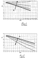
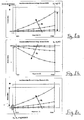
- FIG. 1 was based on the following tilting moment determination of the swiveling or swash plate, with ⁇ being varied from 0 ° to 16 °:
- FIG. 2 shows a diagram for a virtually identical engine, this diagram being based on the following calculation scheme, ⁇ varying from 0 ° to 16 °: Here is the case M k, ges ⁇ M sw .
- Fig. 1 shows the state of the art.
- the aufierde behavior is appropriate Fig. 1 in current R134a series compressor often detectable. at newer developments are more likely to turn this trend into the opposite, namely according to FIG. 2.
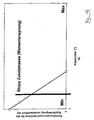
- Fig. 4 the case is still shown, in which the abgresenden overturning moments due to Mass moments of inertia / Deviation moments of the swash plate or the swash plate assembly are dimensioned so that a control behavior results in the case of an increase in the speed of the tilt angle of the swash plate almost constant remains, or decreases, thereby at least a part of the alone by the Speed increase resulting increasing capacity is compensated.
- FIGS. 5, 6 and 7 the tilting moments M SW , M k, ges corresponding to FIGS. 1, 2 and 4 and the sums of the two aforementioned moments are for one rotational speed as a function of the tilting angle of the swashplate or of the geometric displacement volume of the compressor shown.
- the up-regulating characteristic of the compressor can be easily recognized on the basis of the momentum sum in the positive range, while in FIG. 6 the momentum sum is negative for all tilt angles of the swashplate.
- a compressor, which follows the course of the moments according to FIG. 6, has a regulating characteristic.
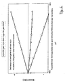
- FIG. 8 a the sum M SW + M k, ges is given for different speeds.
- FIG. 8a corresponds to FIGS. 1 and 5, and clearly shows the total torque that is increasing for increasing rotational speeds.
- Deviationsmoment the swash plate in the case of Figures 8a and 8b at zero tilt angle is zero. That is fall in this example at the swash plate tilt joint and center of gravity together, with no exposed Center of gravity occurs.
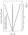
- FIG. 8c shows the behavior of a compressor in which the deviation moment and the resulting tilting moment M SW + M k, ges at a tilt angle of the swash plate of 0 ° is not equal to zero.
- Object of the present invention is to provide a compressor in which the Displacement of the swash plate supported out of a range of small tilt angle out becomes as unwanted side effects as an imbalance or a reinforced Deflection of the swash plate to be avoided at larger tilt angles.
- An essential aspect of the invention is to assign the swash plate an additional mass through which a Deviationmoment the swash plate largely rectified Deviationsmoment is obtained in a range of small tilt angle of the swash plate. It is a moment that is caused by an erection of the additional mass and a torque M SW , which is due to an erection of the swash plate is largely rectified.
- the above-mentioned range of small tilt angle comprises in particular the range of 0 ° to 8 °, preferably even an even smaller tilt angle range of the swash plate, namely the range of 0 ° to 3 °.
- the additional moment of inertia obtained by the additional mass causes the tilting moment of the swashplate to be increased in the region of small tilting angles, preferably in the range of the abovementioned tilting angles, in order to assist in this way the deflection of the swashplate out of this range of small tilting angles.
- This allows an accelerated Aufsteller the compressor. Characterized in that an additional mass Devorational torque attributable to the additional mass is obtained only in the range of small tilt angle, the Aufsteller the compressor is facilitated, while in the range of large tilt angle no negative effects such as an imbalance or undesirable control behavior occur.
- the additional mass is non-rotatable with the drive shaft coupled, but relative to this about an axis transverse to the axis of the drive shaft tiltable stored.
- This provides a structurally simple implementation possibility a compressor according to the invention.
- the tilting movement of the Additional mass regardless of the tilting movement of the swash plate, creating a optimized distribution of the moments of deviation and the tilting moments in the system occur can be achieved. It should be noted that by the above Measure the tilt angle of swashplate and additional mass quasi from each other be decoupled, whereby, for example, the additional mass at a tilt angle of Swivel disc of 0 ° have a significantly different from 0 ° tilt angle can. This is an optimized, desired distribution of the involved Deviationsmomente ensured.
- the additional mass ring or Disc shape on. That So that a construction is chosen in which the additional mass coupled in the form of a disc or a ring to the swashplate mechanism is, with the aufstellende overturning moment of the disc or the ring with the up-regulating Tilting moment cooperates due to the Deviationsmoments the swash plate. In the simplest case of coupling, the moments add up. This means that Defined by the additional mass Deviationsmoment the moment of the Deviation Swivel disk is superimposed.
- the additional mass transmits no moment to the swash plate, but a power transmission takes place, such that a reaction force is formed on the swash plate, the triggers a corresponding additional moment of deviation.
- the additional mass is optimized in an advantageous manner such that the ratio of its moment of inertia and their component mass is as large as possible. The component mass should therefore be as low as possible with a maximum mass moment of inertia.
- an additional ring with an outer diameter, which is only slightly smaller than the inner diameter of the engine housing; if there are other limiting factors for the diameter, is the largest possible outside diameter of such a ring desirable.
- the distance between the additional ring and a housing inner wall should preferably regardless of the tilted position of the additional ring in to be essentially constant.
- the additional mass is partially or substantially within a recess arranged the cylinder block. This ensures on the one hand the proximity of the additional mass to the swash plate, while on the other side through the recess in the cylinder block a compressor with the lowest possible weight is possible.
- the center of gravity of the additional mass is located in a further preferred Embodiment in the range of one of the additional mass associated tilting joint.
- the additional mass with a on the drive shaft slidably mounted sleeve in operative engagement, wherein the above said sleeve in turn with a guide or joint socket of the swash plate mechanism is in operative engagement.
- the additional mass preferably has sites of reduced material accumulation, so that they at a tilt angle of the swashplate of 0 ° has its greatest deviation moment.
- Reduced accumulations of material are in particular due to recesses and / or pockets and / or grooves and / or holes realized.
- one of the additional mass is assigned Tilting limited by at least one arranged on the drive shaft stop.
- Tilting limited by at least one arranged on the drive shaft stop is using simple design means Ensure that the tilting range does not exceed the desired frame.
- the stop or the associated stops in the form of a paragraph formed the drive shaft which is a structurally simple, material-saving variant represents a construction according to the invention.
- the additional mass is preferably in operative engagement with the swashplate in such a manner that substantially a total torque results which corresponds to the sum of two individual moments, namely the moment M SW of the swashplate and a moment M SW, Z of the additional mass corresponding to this. This ensures optimum distribution of the moments in a compressor according to the invention.
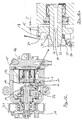
- the axial piston compressor shown in FIGS. 9 and 10 in longitudinal section for the Air conditioning system of a motor vehicle comprises an engine housing 10, which cup-shaped is formed, and at the peripheral edge of a cylinder block 12 connects. Within the cylinder block 12 are a plurality, preferably 5, 6 or 7 axially reciprocating Plunger arranged, wherein the distribution of the pistons around the housing center axis 18th is uniform around. Through the bottom of the cup-shaped housing 10 therethrough extends over a pulley 21 driven drive shaft 11 in the Housing interior or in an engine room 22 inside. The bearing of the drive shaft takes place on the one hand in the region of the bottom of the pot-shaped housing 10 and on the other within the cylinder block 12.
- a swashplate mechanism effective, by the rotational movement of the drive shaft 11 in Axial movement of the piston 13 is implemented.
- a swivel disk engages in the form of a swash plate 14 with its peripheral edge via a hinge assembly in C-shaped recesses on the back of the piston 13 a.
- the Joint arrangement is as in the prior art by two spherical segment-like Hinges 16, 17 defined, between which the swash plate 14 slidably engages.
- the spherical bearing surfaces of the joint stones 16, 17 are corresponding spherical Troughs on the mutually facing end faces of the C-shaped recesses of the Piston 13 assigned.
- Inlet and outlet valves in a conventional, for example from the prior art arranged in a known manner.
- the tilt angle of the swash plate 14 is between the positions shown in FIG. 9 and Fig. 10 variable, wherein in Fig. 9, the tilt angle of the swash plate 14 minimal and in Fig. 10 is maximum. Accordingly, the stroke of the piston 13 is minimal or maximum.
- the swash plate 14 is assigned an additional mass in the form of an additional disk 15.
- the additional mass in the form of additional disk 15 is via a joint in the form of two bolts 19 (see in particular Fig. 11) attached to the drive shaft 11.
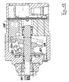
- the Additional disk 15 is arranged in a recess 18 in the cylinder block 12. This poses a compact design of the compressor safely, with the recess in the cylinder block In addition, a weight saving is realized.
- the additional disc 15 is with respect to an axis of the joint, by means of which they at the Drive shaft is fixed, tiltably mounted.
- the additional disk 15 can be in one area be tilted from 0 ° to 3 ° about the axis mentioned above, which is transverse to a Drive shaft central axis 20 which at the same time the central axis of the housing represents.
- the angle of maximum deflection is by a stop 23 in the form of a Paragraph set on the drive shaft 11.
- the additional disc 15 is connected to a part its an engine compartment 22 facing surface 24 with a sleeve 25 in operative engagement, in turn, with a guide or joint socket of the swashplate mechanism is in operative engagement. Accordingly, the tilting moment causes the Additional disk 15 a force F (in Fig. 9a indicated), which is a tilting moment in the swashplate mechanism induced in the direction of a larger tilt angle.
- the swivel mechanism and the mechanism of the additional disc 15 separated from a tilt angle of 3 °. So that means in others Words said that the swash plate including its additional mass at a minimum tilt angle is supported during the Aufregeln, while at larger tilt angles the Aufspr supporting additional disk 15 has no influence on the control behavior of the compressor has more.
- the swash plate 14 and the entire swash plate mechanism is so designed that, especially at high angles of tilt and high speeds, the swash plate has a declining tendency.
- Fig. 11 the engine according to the figures 9 and 10 is shown in exploded view.
- the additional disk 15 is, as already in the description of FIGS. 9 and 10 indicated by means of two hinge pins 19 on the drive shaft 11 in a direction transverse tiltably mounted to the longitudinal extent.
Landscapes
- Engineering & Computer Science (AREA)
- Mechanical Engineering (AREA)
- General Engineering & Computer Science (AREA)
- Compressors, Vaccum Pumps And Other Relevant Systems (AREA)
Abstract
Description
- Moment infolge der Gaskräfte in den Zylinderräumen (+)
- Moment infolge der Gaskräfte aus dem Triebwerksraum (-)
- Moment infolge einer Rückstellfeder (-)
- Moment infolge einer Aufstellfeder (+)
- Moment infolge rotierender Massen (-); inklusive Moment infolge Schwerpunktlage (zum Beispiel Schwenkscheibe: Kipp-Position ≠ Massenschwerpunkt): kann (+) oder (-) sein
- Moment infolge der translatorisch bewegten Massen (+)
600 U/min, 1200 U/min, 2500 U/min, 5000 U/min, 8000 U/min und 11000 U/min.
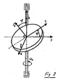
- α2 = 90°
- β2 = ψ Richtungswinkel der y-Achse gegenüber den
- γ2 = 90° + ψ Hauptträgheitsachsen ξ ·η ·ζ
- α3 = 90°
- β3 = 90°-ψ Richtungswinkel der z-Achse gegenüber den
- γ3 = ψ Hauptträgheitsachsen ξ ·η ·ζ
Ziel: Jyz soll eine bestimmte Größe haben
Jyz ↑ } J3 ↑ J2 erhöht sich zwangsläufig!)

-
- Drehwinkel der Welle (wobei die vor- und nachstehenden Betrachtungen der Einfachheit halber für =0 angestellt werden)
- η
- Anzahl der Kolben
- R
- Abstand der Kolbenachse zur Wellenachse
- ω
- Wellendrehzahl
- α
- Kippwinkel des Schwenkringes/Schwenkscheibe
- mk
- Masse eines Kolbens inklusive Gleitsteine bzw. Gleitsteinpaar
- mk,ges
- Masse aller Kolben inklusive Gleitsteine
- msw
- Masse des Schwenkringes
- ra
- Außenradius des Schwenkringes
- ri
- Innenradius des Schwenkringes
- h
- Höhe des Schwenkringes
- ρ
- Dichte des Schwenkringes
- V
- Volumen des Schwenkringes
- βi
- Winkelposition des Kolbens i
- zi
- Beschleunigung des Kolbens i
- Fmi
- Massenkraft des Kolbens i (inklusive einem Gleitsteinpaar)
- M(Fmi)
- Moment infolge der Massenkraft des Kolbens i
- Mk,ges
- Moment infolge der Massenkraft aller Kolben
- Msw
- Moment infolge des Aufstellmomentes des Schwenkringes/Schwenkscheibe bzw. infolge des Deviationsmoments (Jyz)
- J =
- f (ρ, r, h) Massenträgheitsmoment


- Fig. 9
- einen erfindungsgemäßen Verdichter im Längsschnitt, wobei das Triebwerk sich in einer Stellung für minimalen Kolbenhub befindet;
- Fig. 9a
- eine Detailansicht eines Ausschnitts des in Fig. 9 dargestellten Verdichters;
- Fig. 10
- einen Verdichter entsprechend Fig. 9, wobei das Triebwerk sich in einer Stellung befindet, in der der Kolbenhub maximal ist;
- Fig. 10a
- eine Detailansicht eines Ausschnitts des in Fig. 10 dargestellten Verdichters;
- Fig. 11
- das Triebwerk des Verdichters gemäß den Figuren 9 und 10 in perspektivischer Explosionsdarstellung; und
- Fig. 12
- eine Darstellung des für die Kippbewegung der Schwenkscheibe verantwortlichen Deviationsmoments in Abhängigkeit vom Kippwinkel derselben.
- 10
- Gehäuse
- 11
- Antriebswelle
- 12
- Zylinderblock
- 13
- Kolben
- 14
- Schrägscheibe
- 15
- Zusatzscheibe (Zusatzmasse)
- 16
- Gleitstein
- 17
- Gleitstein
- 18
- Ausnehmung im Zylinderblock
- 19
- Gelenkstift
- 20
- Antriebswellen-Mittelachse
- 21
- Riemenscheibe
- 22
- Triebwerksraum
- 23
- Anschlag
- 24
- der Triebwerkskammer zugewandte Seite der Zusatzscheibe 15
- 25
- Hülse
- 26
- Zylinderkopf
- 114
- Antriebswelle
- 117
- erste Mitnehmerkomponente
- 118
- Schrägscheibe
- 119
- zweite Mitnehmerkomponente
- 120
- Kolben
- 121
- Gleitstein
Claims (10)
- Axialkolbenverdichter, insbesondere Verdichter für die Klimaanlage eines Kraftfahrzeugs, mit einem Gehäuse (10) und einer in dem Gehäuse (10) angeordneten, über eine Antriebswelle (11) angetriebene Verdichtereinheit zum Ansaugen und Verdichten eines Kältemittels, wobei die Verdichtereinheit in einem Zylinderblock (12) axial hin- und herlaufende Kolben (13) und eine die Kolben (13) antreibende, mit der Antriebswelle (11) drehende Schwenkscheibe (Schwenkring; Taumel- oder Schrägscheibe (14)) umfaßt,
dadurch gekennzeichnet, daß
der Schwenkscheibe (14) eine Zusatzmasse (15) zugeordnet ist, durch die in einem Bereich kleiner Kippwinkel der Schwenkscheibe (14), insbesondere in einem Kippwinkelbereich von 0° bis 8°, insbesondere 0° bis 3°, ein einem Moment (MSW) infolge eines Aufstellmoments der Schwenkscheibe (14) weitestgehend gleichgerichtetes Moment infolge eines Aufstellmoments der Zusatzmasse erhalten wird, derart, daß das Kippmoment der Schwenkscheibe (14) infolge des Deviationsmoments derselben in dem vorgenannten Kippwinkelbereich erhöht wird, um auf diese Weise die Auslenkung der Schwenkscheibe (14) aus einem Bereich kleiner Kippwinkel heraus zu unterstützen (beschleunigtes Aufregeln des Verdichters). - Verdichter nach Anspruch 1,
dadurch gekennzeichnet, daß
die Zusatzmasse (15) mit der Antriebswelle (11) drehfest gekoppelt, jedoch relativ zu dieser um eine Achse quer zur Achse der Antriebswelle (11) kippbar gelagert ist. - Verdichter nach Anspruch 1 oder 2,
dadurch gekennzeichnet, daß
die Kippbewegung der Zusatzmasse (15) unabhängig von der Kippbewegung der Schwenkscheibe (14) ist. - Verdichter nach einem der vorangehenden Ansprüche,
dadurch gekennzeichnet, daß
die Zusatzmasse (15) Ring- oder Scheibenform aufweist. - Verdichter nach einem der vorangehenden Ansprüche,
dadurch gekennzeichnet, daß
die Zusatzmasse (15) teilweise oder weitgehend innerhalb einer Ausnehmung (18) des Zylinderblocks (12) angeordnet ist. - Verdichter nach einem der vorangehenden Ansprüche,
dadurch gekennzeichnet, daß
die Zusatzmasse (15) ihren Massenschwerpunkt im Bereich eines ihr zugeordneten Kippgelenks hat, wobei der Massenschwerpunkt in etwa auf einer Mittelachse der Antriebswelle (11) liegt. - Verdichter nach einem der vorangehenden Ansprüche,
dadurch gekennzeichnet, daß
die Zusatzmasse (15) mit einer auf der Antriebswelle (11) verschiebbar gelagerten Hülse (25) in Wirkeingriff steht, die mit einer Führungs- oder Gelenkbuchse des Schrägscheibenmechanismus in Wirkeingriff steht. - Verdichter nach einem der vorangehenden Ansprüche,
dadurch gekennzeichnet, daß
die Zusatzmasse (15) Stellen reduzierter Materialansammlung, insbesondere Ausnehmungen und/oder Taschen und/oder Nuten und/oder Bohrungen aufweist derart, daß sie bei einem Kippwinkel der Schwenkscheibe (14) von 0° ihr größtes Deviationsmoment besitzt. - Verdichter nach einem der vorangehenden Ansprüche,
dadurch gekennzeichnet, daß
ein Kippbereich der Zusatzmasse (15) durch mindestens einen an der Antriebswelle (11) angeordneten Anschlag (23) begrenzt ist, welcher vorzugsweise in Form eines Absatzes der Antriebswelle (11) vorliegt. - Verdichter nach einem der vorangehenden Ansprüche,
dadurch gekennzeichnet, daß
die Zusatzmasse (15) mit der Schwenkscheibe (14) derart in Wirkeingriff steht, daß sich weitgehend ein Gesamtmoment in Form der Summe der beiden Momente MSW der Schwenkscheibe (14) und MSW,Z der Zusatzmasse (15) ergibt.
Applications Claiming Priority (2)
| Application Number | Priority Date | Filing Date | Title |
|---|---|---|---|
| DE200410027321 DE102004027321A1 (de) | 2004-06-04 | 2004-06-04 | Axialkolbenverdichter |
| DE102004027321 | 2004-06-04 |
Publications (2)
| Publication Number | Publication Date |
|---|---|
| EP1602829A2 true EP1602829A2 (de) | 2005-12-07 |
| EP1602829A3 EP1602829A3 (de) | 2009-09-30 |
Family
ID=34936452
Family Applications (1)
| Application Number | Title | Priority Date | Filing Date |
|---|---|---|---|
| EP05010358A Withdrawn EP1602829A3 (de) | 2004-06-04 | 2005-05-12 | Axialkolbenverdichter |
Country Status (2)
| Country | Link |
|---|---|
| EP (1) | EP1602829A3 (de) |
| DE (1) | DE102004027321A1 (de) |
Cited By (1)
| Publication number | Priority date | Publication date | Assignee | Title |
|---|---|---|---|---|
| EP2067995A1 (de) * | 2007-12-03 | 2009-06-10 | Valeo Compressor Europe GmbH | Schwenkscheibenverdichter |
Family Cites Families (11)
| Publication number | Priority date | Publication date | Assignee | Title |
|---|---|---|---|---|
| CS172656B1 (de) * | 1974-06-24 | 1977-01-28 | ||
| US4836090A (en) * | 1988-01-27 | 1989-06-06 | General Motors Corporation | Balanced variable stroke axial piston machine |
| US4815358A (en) * | 1988-01-27 | 1989-03-28 | General Motors Corporation | Balanced variable stroke axial piston machine |
| JP3417652B2 (ja) * | 1994-04-21 | 2003-06-16 | 株式会社豊田自動織機 | 容量可変型斜板式圧縮機 |
| DE19616961C2 (de) * | 1996-04-27 | 2002-11-07 | Daimler Chrysler Ag | Hubkolbenmaschine mit Taumelscheibengetriebe |
| JPH10246181A (ja) * | 1997-02-28 | 1998-09-14 | Toyota Autom Loom Works Ltd | 可変容量型圧縮機 |
| DE19749727C2 (de) * | 1997-11-11 | 2001-03-08 | Obrist Engineering Gmbh Lusten | Hubkolbenmaschine mit Schwenkscheibengetriebe |
| DE19839914A1 (de) * | 1998-09-02 | 2000-03-09 | Luk Fahrzeug Hydraulik | Axialkolbenmaschine |
| JP2001295755A (ja) * | 2000-04-17 | 2001-10-26 | Toyota Industries Corp | 可変容量圧縮機のガイドピン及び可変容量圧縮機 |
| JP2002031043A (ja) * | 2000-07-14 | 2002-01-31 | Toyota Industries Corp | 圧縮機 |
| US7320576B2 (en) * | 2002-08-27 | 2008-01-22 | Sanden Corporation | Clutchless variable displacement refrigerant compressor with mechanism for reducing displacement work at increased driven speed during non-operation of refrigerating system including the compressor |
-
2004
- 2004-06-04 DE DE200410027321 patent/DE102004027321A1/de not_active Withdrawn
-
2005
- 2005-05-12 EP EP05010358A patent/EP1602829A3/de not_active Withdrawn
Cited By (1)
| Publication number | Priority date | Publication date | Assignee | Title |
|---|---|---|---|---|
| EP2067995A1 (de) * | 2007-12-03 | 2009-06-10 | Valeo Compressor Europe GmbH | Schwenkscheibenverdichter |
Also Published As
| Publication number | Publication date |
|---|---|
| DE102004027321A1 (de) | 2005-12-22 |
| EP1602829A3 (de) | 2009-09-30 |
Similar Documents
| Publication | Publication Date | Title |
|---|---|---|
| DE10222388A1 (de) | Kompressor mit veränderbarer Verdrängung | |
| WO2006111264A1 (de) | Axialkolbenverdichter | |
| DE10315477A1 (de) | Axialkolbenverdichter, insbesondere CO2-Verdichter für Kraftfahrzeug-Klimaanlagen | |
| EP1844234B1 (de) | Axialkolbenverdichter | |
| DE19947677B4 (de) | Axialkolbenverdichter | |
| EP1673537B1 (de) | Axialkolbenverdichter, insbesondere verdichter für die klimaanlage eines kraftfahrzeuges | |
| EP1718867B1 (de) | Axialkolbenverdichter, insbesondere verdichter für die klimaanlage eines kraftfahrzeuges | |
| EP1602829A2 (de) | Axialkolbenverdichter | |
| DE10354038B4 (de) | Axialkolbenverdichter, insbesondere Verdichter für die Klimaanlage eines Kraftfahrzeuges | |
| EP1766234A1 (de) | Axialkolbenverdichter, insbesondere verdichter für die klimaanlage eines kraftfahrzeuges | |
| DE10329393A1 (de) | Axialkolbenverdichter, insbesondere Kompressor für de Klimaanlage eines Kraftfahtzeuges | |
| DE60213927T2 (de) | Kompressor mit variabler Verdichtung | |
| DE10354039B4 (de) | Axialkolbenverdichter, insbesondere Verdichter für die Klimaanlage eines Kraftfahrzeuges | |
| EP1636492B1 (de) | Axialkolbenverdichter, insbesondere kompressor für die klimaanlage eines kraftfahrzeuges | |
| DE102005039199A1 (de) | Axialkolbenverdichter | |
| DE102005033706A1 (de) | Axialkolbenverdichter | |
| DE102005018075A1 (de) | Taumelscheiben-Verstellkompressor | |
| WO2008025412A1 (de) | Axialkolbenverdichter | |
| WO2007134665A1 (de) | Verfahren zum regeln des kältemittel-massenstroms eines verdichters | |
| DE102006029875A1 (de) | Verfahren zum Regeln des Kältemittel-Massenstroms eines Verdichters | |
| DE10324802A1 (de) | Axialkolbenverdichter, insbesondere CO2-Verdichter für Kraftfahrzeug-Klimaanlagen | |
| DE102007058064A1 (de) | Verdichter | |
| DE102005028690A1 (de) | Kompressor mit variabler Verdrängung | |
| WO2009015726A1 (de) | Hubkolbenmaschine | |
| DE102008008355A1 (de) | Verdichter |
Legal Events
| Date | Code | Title | Description |
|---|---|---|---|
| PUAI | Public reference made under article 153(3) epc to a published international application that has entered the european phase |
Free format text: ORIGINAL CODE: 0009012 |
|
| AK | Designated contracting states |
Kind code of ref document: A2 Designated state(s): AT BE BG CH CY CZ DE DK EE ES FI FR GB GR HU IE IS IT LI LT LU MC NL PL PT RO SE SI SK TR |
|
| AX | Request for extension of the european patent |
Extension state: AL BA HR LV MK YU |
|
| RAP1 | Party data changed (applicant data changed or rights of an application transferred) |
Owner name: VALEO COMPRESSOR EUROPE GMBH |
|
| PUAL | Search report despatched |
Free format text: ORIGINAL CODE: 0009013 |
|
| AK | Designated contracting states |
Kind code of ref document: A3 Designated state(s): AT BE BG CH CY CZ DE DK EE ES FI FR GB GR HU IE IS IT LI LT LU MC NL PL PT RO SE SI SK TR |
|
| AX | Request for extension of the european patent |
Extension state: AL BA HR LV MK YU |
|
| RIC1 | Information provided on ipc code assigned before grant |
Ipc: F04B 27/10 20060101ALI20090826BHEP Ipc: F04B 27/18 20060101AFI20050609BHEP |
|
| STAA | Information on the status of an ep patent application or granted ep patent |
Free format text: STATUS: THE APPLICATION IS DEEMED TO BE WITHDRAWN |
|
| 18D | Application deemed to be withdrawn |
Effective date: 20091201 |