EP1602419A1 - Press for cutting high strength metal sheets - Google Patents
Press for cutting high strength metal sheets Download PDFInfo
- Publication number
- EP1602419A1 EP1602419A1 EP05010716A EP05010716A EP1602419A1 EP 1602419 A1 EP1602419 A1 EP 1602419A1 EP 05010716 A EP05010716 A EP 05010716A EP 05010716 A EP05010716 A EP 05010716A EP 1602419 A1 EP1602419 A1 EP 1602419A1
- Authority
- EP
- European Patent Office
- Prior art keywords
- press
- press according
- plunger
- workpiece
- hydraulic
- Prior art date
- Legal status (The legal status is an assumption and is not a legal conclusion. Google has not performed a legal analysis and makes no representation as to the accuracy of the status listed.)
- Granted
Links
Images


Classifications
-
- B—PERFORMING OPERATIONS; TRANSPORTING
- B21—MECHANICAL METAL-WORKING WITHOUT ESSENTIALLY REMOVING MATERIAL; PUNCHING METAL
- B21D—WORKING OR PROCESSING OF SHEET METAL OR METAL TUBES, RODS OR PROFILES WITHOUT ESSENTIALLY REMOVING MATERIAL; PUNCHING METAL
- B21D28/00—Shaping by press-cutting; Perforating
- B21D28/02—Punching blanks or articles with or without obtaining scrap; Notching
- B21D28/20—Applications of drives for reducing noise or wear
-
- B—PERFORMING OPERATIONS; TRANSPORTING
- B21—MECHANICAL METAL-WORKING WITHOUT ESSENTIALLY REMOVING MATERIAL; PUNCHING METAL
- B21D—WORKING OR PROCESSING OF SHEET METAL OR METAL TUBES, RODS OR PROFILES WITHOUT ESSENTIALLY REMOVING MATERIAL; PUNCHING METAL
- B21D24/00—Special deep-drawing arrangements in, or in connection with, presses
- B21D24/10—Devices controlling or operating blank holders independently, or in conjunction with dies
Definitions
- the invention relates to a press, in particular designed for cutting thick and / or high-strength sheets is.
- the press has according to claim 1 a sheet holding device on the tool during the forming process pressed against the lower tool.
- the lower tool is for example a punching tool while the upper tool, for example a stamp is.
- the sheet holding device is able to exercise different forces.
- One of the Sheet holding device associated control device can the influence force exerted by the sheet holding device.
- the sheet holding device usually belongs a Retainer plate, which is located directly on the workpiece supported.
- the hold-down plate extends into immediate Neighborhood to the stamps (punch stamps) and thus close up to the section to be produced.
- the sheet holding device takes over after the breakthrough of the stamp by the Workpiece the force applied by the plunger during this goes through its bottom dead center and saves the from energy delivered by the plunger thereby. In which Return stroke of the plunger will transfer this energy to the plunger and thus given back to the press drive.
- the press drive relieved overall, i. Energy is saved.
- the mechanical load on the press reduced by avoiding too large sudden force changes.
- the transfer of the bis to the workpiece breakthrough on the punch force applied the sheet holding device a particularly firm clamping of Workpiece just during the breakthrough, so that special high cutting qualities result.
- the Force over the sheet holding device particularly large area and thus gently introduced into the workpiece, so that undesirable deformations thereof, such as Bruising and the like, can be avoided.
- the control device therefore the influence of the support device applied force only within a specified Path section of the ram movement free. In this way Become error detectors that are otherwise too gross malfunction lead the press, certainly excluded.
- the fixed path portion preferably has an adjustable Start ⁇ 1 or x1 on.
- he may preferably have a variably adjustable end ⁇ 2 or x2.
- Its length can be variable and adjustable.
- the sheet holding device or the Supporting a hydraulic cylinder, which with a first and with a second hydraulic accumulator connected is.
- Both accumulators have e.g. one displaceable stored piston with damped end stop on.
- membrane storage devices or storage devices be provided, in which a gas pressure cushion directly in communication with the hydraulic fluid.
- Both pressure accumulators preferably have different Resting pressures on.
- the from the hydraulic cylinder to the accumulator the lower pressure route is preferred regulated by a valve which controls the flow of fluid, i. the mass flow monitors and closes when this is a limit exceeds.
- This flow-sensitive valve is a advantageous variant of a sensor device, the Detection of the breakthrough of the workpiece is used.
- a corresponding path measuring device or other Transmitter device can also be used to obtain a signal used to determine the activation window within which the punch breakthrough is expected becomes. The puncture breakthrough is then monitored only in this activation window while outside the activation window the support device is passive or the Sheet holding device only their Blechhaltefunktion Fulfills.
- a press 1 illustrates a press frame with press stands 2, 3, a press table 4 and a head piece 5 has.
- a drive 6 held for example in the form of an electric motor, the via a schematically illustrated and dashed shown eccentric 7 and also dashed illustrated connecting rod 8 a plunger 9 going back and forth drives.
- a plunger 9 going back and forth drives.
- a tool 10 with an upper tool 11 and a lower tool 12 provided.
- the lower tool 12 is as Punching tool formed.
- stamp 13, 14, 15 On the upper tool 11 are stamp 13, 14, 15, which, like the other details of the Tool 10 can be seen in particular from Figure 2.
- the Tool 10 is used for punching a workpiece 16, the in Figure 2 is illustrated as a flat workpiece. Of course However, also not flat workpieces in the corresponding Be subjected to a punching process. In In this case, the lower tool 12 then does not have one level workpiece corresponding contour.
- To the upper tool 11 includes a sheet holder plate 17, the means not further illustrated on a Main body 18 of the upper tool 11 is held.
- the one with The main body 18 connected to the tappet 9 carries the punches 13 to 15, which are thereby rigidly connected to the plunger 9.
- the base body 18 includes one or more hydraulic cylinders 19, 20, which together with the sheet holder plate 17 form a sheet holding device 21.
- To the sheet holding device 21 also includes push pins 22 to 27, the approximately or exactly parallel to the stamps 13 to 15 are arranged and with their lower frontal Support end on the sheet metal holder plate 17. The rest, by the way essentially cylindrical pins support themselves with their upper front end of floating plates 28, 29 from, the thus lie on top of the pressure pins 22 to 27.
- Hydraulic cylinders 19, 20 include pistons 30, 31 which are in the Hydraulic cylinders 19, 20 corresponding with hydraulic fluid filled working spaces 32, 33 demarcate and sealed and are slidably stored in these. Piston rods 34, 35 the piston 30, 31 press from above on the floating plates 28, 29 and thus the sheet holder plate 17 against the Workpiece 16.
- the hydraulic cylinders 19, 20 are over one in Figure 2 not and shown in Figure 1 only schematically Fluid line 36 connected to a hydraulic system 37, the to produce a blank holder force and at the same time to take over the force exerted by the plunger 9 during and after Breakthrough of the workpiece 16 is used.
- This power transition should as infinitely as possible, i. without sudden force change respectively.
- the hydraulic system 37 includes a first accumulator 38 and a second pressure accumulator 39, which in the embodiment both as accumulator cylinder 40, 41 with sealed therein, slidably mounted pistons 42, 43 are formed. Both pistons 42, 43 share in the accumulator cylinders 40, 41 each from two working chambers, the upper, each filled with a gas cushion.
- Pressure accumulator 38 is, for example, under a pressure of about 200 bar while the accumulators 39 e.g. under a pressure of e.g. 400 bar stands.
- the pistons 42, 43 have at their lower, the respective End pieces 44, 45 facing side preferably a profiling that is complementary to a profiling of the respective end piece 44, 45 is formed.
- the profiling is achieved by straight or curved, e.g. annular formed concentric strips or webs, wherein the Ledges or webs of each piston 42, 43 in correspondingly shaped Recesses of each end piece 44, 45 fit.
- the Profilings serve as cushioning, so that the pistons 42, 43, when they run against the fittings 44, 45, be braked gently.
- Both pressure accumulators 38, 39 are connected to the fluid line 36 connected.
- the pressure accumulator 39 via a Check valve 46 and a throttle device 47 to the Fluid line 36 connected.
- the check valve 46 is in so doing oriented so that the hydraulic fluid from the hydraulic line 36 freely flow into the accumulator 40 can while it's on its way back through the throttle 47 is forced.
- the pressure accumulator 38 is connected via a valve device 48 to the fluid line 36 and thus the hydraulic cylinders 19, 20.
- the valve device 48 includes, for example, a directional control valve 49 which is switchable between two states. In a first state, the fluid flow into and out of the pressure accumulator 38 is unrestricted or restricted, while in its other state it blocks this fluid flow.
- the valve device 48 may be connected to a sensor device 50 which, for example, monitors and closes the mass flow m ⁇ in the fluid line 36 as soon as this hydraulic flow directed into the pressure accumulator 38 exceeds a threshold value m th and then remains closed until the pressure in the fluid line 36 drops below a threshold.
- the sensor device 50 thus forms at the same time Control device 51 for controlling the valve device 48 depending on the speed of the relative movement between the pistons 28, 29 of the hydraulic cylinders 19, 20 and the plunger 9.
- a bypass valve 52 include the valve means 48 bridges and thus an alternative path from the hydraulic cylinders 19, 20 to the pressure accumulator 38 creates.
- the By-pass valve 52 is, for example, an open / close valve can be controlled electrically pneumatically or otherwise.
- a control device 53 preferably as a microprocessor control or as other suitable electronic control can be trained.
- FIG. 3 illustrates an embodiment of the invention Valve device 48, because of its fast response time is preferred. It has a base body 56 which provided with at least one input 57 and with an output 58 is. Between both a channel 59 is formed, the passes longitudinally through the base body 6 and to which the channels the input 57 and the output 58 are directed transversely. Between the input 57 and the output 58 is a valve seat 60 formed, which is a valve closure member in the form associated with a disk 61. The latter sits on one Pin and is by a spring in the opening direction of the Valve seat 60 biased away. The bias can be required by means of an externally accessible handle, for example an adjusting screw 62 can be adjusted.
- the blank holder plate 17 touches the workpiece 16, it presses the workpiece 16 against the lower tool 12.
- the blank holder plate 17 thus stops while the plunger 9 moves toward the workpiece 16. Also remain standing the pressure pins 22 to 27, the floating plates 28, 29 and the pistons 30, 31.
- the volume of the working chambers 32, 33 is reduced and hydraulic fluid via the fluid line 36 and the open directional control valve 49th the valve device 48 is driven into the pressure accumulator 38, which has a lower static pressure than the pressure accumulator 39.
- the piston 43 is moved in Figure 1 against the force of the upper gas cushion upwards.
- the fluid flow m ⁇ occurring in this process is below a threshold value, so that the sensor device 50 does not respond.
- a more refined embodiment uses the control device 53 to control the sheet metal holder device or an alternative supporting device, for example in the form of hydraulic cylinders between the plunger 9 and the press table 4 or the upper tool 11 and the lower tool 12.
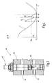
- the conditions are illustrated in Figure 4. It is assumed that a press with a high stroke rate.
- a first curve I illustrates the path X of the plunger 9 over the rotation angle ⁇ of the eccentric shaft. It is assumed that there is an approximate sinusoidal relationship.
- the sheet holder plate 17 is set on the workpiece.
- the curve II illustrates the mass flow of the displaced from the hydraulic cylinders 19, 20 hydraulic fluid.
- a press angle ⁇ 1 which certainly after the Placing the blank holder plate 17 on the workpiece 16 and certainly before the breakthrough of the stamps 13, 14, 15 through the workpiece 16, locks the controller 53 now the bypass valve 52, whereby the sensor device 50th is activated.
- the crank or press angle ⁇ 1 can as a criterion for releasing the sensor device 50 and the valve device 48 are also used that the Tappet 9 passes through the point x1.
- the monitoring is the press angle preferred because of this better Resolution offers.
- the threshold m ⁇ th for the valve device 48 can be set very low, so that the otherwise observed punching stroke on a almost no more perceptible minimum.
- the fluid flow monitored from the hydraulic cylinders 19, 20, can also find other sensor devices application.
- this Press angle ⁇ 1, ⁇ 2 dynamically adapt. This can be, for example done by placing ⁇ 1 in a given or insertable angular distance before punching breakthrough and ⁇ 2 in a fixed or adjustable angular distance after the Punch breakthrough is set. As press angle of the Punch breakthrough is then the press angle from the previous punch stroke or an average value from previous Used punching strokes.
- the press frame, the press table or other parts of the press Force sensors to accommodate a deformation of the concerned press element or directly on in the Press acting force.
- Such can be, for example Be force sensors in the tool 10.
- the ones of these Sensors emitted signals can be sent to the control device 53 are guided and serve the press angle ⁇ 1, ⁇ 2 set.
- the sensor device 50 can a time, i. then be released when to the Stamping 13, 14, 15 recorded a significant increase in strength is. There is no false trip at this time the valve device 48 to fear more, because the relative movement between the blank holder plate 17 and the punches 13, 14, 15 is almost zero.
- the system according to the invention allows a substantial Increase the holding force, especially during the Performing the punching operation, i. while the stamps 13, 14, 15 penetrate through the material of the workpiece.
- the real one Cutting force can thereby up to a sixth of the theoretical thrust can be lowered.
- the sheet holding device 21 causes a particularly firm clamping of Workpiece 16 and thus causes an improvement of Cut as well as a cutting shock absorption.
- the press 1 is so biased that compensates or compensates for games become. This leads compared to classical cutting impact damping systems for reducing the total pressing force of the system. This also means that older Presses continue even for difficult separation operations can be used.
- the force exerted on the sheet holder plate Force is preferably about 40% of the pressing force designed.
- the separation process can be achieved by using a fast evaluation and control device, such as the Control device 53, monitored, evaluated and controlled become.
- the system can be largely self-sufficient, i. of the Press 1 independently trained and used. For example It can be part of the tool, and thus in principle be used in different presses.
- At Change of press data can be press-specific parameters changed via program or system-specific flashcards become.
- the pressures in the hydraulic cylinders 19, 20 can encoder- or path-dependent permanently monitored.
- the resulting envelopes allow for permanent process monitoring.
- the control of the bypass valve 52 takes place crank angle or path dependent on the same system.
- the process data and faults can be accessed via data storage systems stored and tracked in case of damage. In addition, systems for detecting overload cases be provided.
- a sheet holder 21st provided that the relevant workpiece 16 during the Clamping firmly clamped.
- the clamping force will increase up to 40% or more percent of the ram force increased.
- the force exerted by the sheet holding device during the workpiece breakthrough be increased again.
- an efficient cutting impact reduction or prevention at the press results.
- a cutting blow is significantly weakened or does not occur.
Abstract
Description
Die Erfindung betrifft eine Presse, die insbesondere zum Schneiden von dicken und/oder hochfesten Blechen eingerichtet ist.The invention relates to a press, in particular designed for cutting thick and / or high-strength sheets is.
Beim Stanzen oder Schneiden von hochfesten Blechen treten zwischen Stößel und Stanzwerkzeug zeitlich sehr stark schwankende Kräfte auf. So lange das Material des Werkstücks dem Stempel widersteht, ist eine sehr hohe Kraft vorhanden, wodurch Teile der Presse elastisch verformt werden. Dies betrifft den Pressentisch, das Stanzwerkzeug, die Pressenständer, das Pressenkopfstück und in gewissem Maße auch den Stößel nebst Pleuel und Exzenterwelle. Wenn das Werkstück unter der Wirkung des Stempels nachgibt, wird die in den genannten Elementen elastisch gespeicherte Energie relativ unkontrolliert frei. Um diesen Vorgang des plötzlichen Durchbrechens des Stempels durch das Werkstück besser kontrollieren zu können, schlägt die DE 102 52 625 A1 ein System zur Schnittschlagreduzierung vor, bei dem in dem Werkzeug eine Anzahl von Hydraulikzylindern vorgesehen sind. Diese können unterhalb, oberhalb oder seitlich von dem Werkstück angeordnet sein. Sensoren, wie beispielsweise Ultraschallsensoren, oder auch Sensoren, die die Strömungsgeschwindigkeit der aus den Hydraulikzylindern ausströmenden Hydraulikflüssigkeit messen, schließen ein Ventil, durch das bislang Hydraulikflüssigkeit aus den Hydraulikzylindern ausströmen konnte. Die Hydraulikzylinder sind mit Druckspeichern verbunden, die unter relativ hohem Druck stehen. Sie erzeugen deshalb nunmehr eine hohe Gegenkraft. Die bislang von dem Stempel auf das Werkstück ausgeübte Kraft wird somit in dem Moment auf die Hydraulikzylinder übergeleitet, in dem die Stempel beginnen, durch das Werkstück durchzubrechen.When punching or cutting of high-strength sheets occur between ram and punching tool very strong in time fluctuating forces. As long as the material of the workpiece resisting the stamp, there is a very high force whereby parts of the press are elastically deformed. This relates to the press table, the punching tool, the press stands, the press head and to some extent the Plunger together with connecting rod and eccentric shaft. If the workpiece under the action of the stamp yields, in the said elements elastically stored energy relative uncontrolled free. To this process of sudden Better control the puncture of the punch by the workpiece to be able to DE 102 52 625 A1 proposes a system for cutting impact reduction, in which in the tool a number of hydraulic cylinders are provided. These can be below, above or to the side of the workpiece be arranged. Sensors, such as ultrasonic sensors, or even sensors that measure the flow rate the effluent from the hydraulic cylinders Measure hydraulic fluid, close a valve, through the So far hydraulic fluid from the hydraulic cylinders flow out could. The hydraulic cylinders are with pressure accumulators connected, which are under relatively high pressure. she Therefore now generate a high drag. The so far force exerted by the punch on the workpiece thus becomes in the moment transferred to the hydraulic cylinder, in the the punches begin to break through the workpiece.
Dieser Weg zur Schnittschlagdämpfung hat sich grundsätzlich bewährt. Jedoch ist die Einstellung der Sensoren zur Erfassung des Werkstückdurchbruchs kritisch. Auch ist bei Anordnung der Hydraulikzylinder neben dem Werkzeug noch ein gewisser Schnittschlag vorhanden, der weiter reduziert werden soll.This way to cut impact damping has basically proven. However, the setting of the sensors to detect the workpiece breakthrough critical. Also is when arranging the hydraulic cylinder next to the tool yet a certain cutting blow exists, which further reduces shall be.
Davon ausgehend ist es Aufgabe der Erfindung, den genannten Stand der Technik zu verbessern. On this basis, it is an object of the invention, the above To improve the state of the art.
Diese Aufgabe wird mit der Presse nach Anspruch 1 sowie nach Anspruch 11 gelöst:This object is achieved with the press according to claim 1 and solved according to claim 11:
Die Presse weist nach Anspruch 1 eine Blechhalteeinrichtung auf, die das Werkzeug während des Umformvorgangs gegen das Unterwerkzeug presst. Das Unterwerkzeug ist beispielsweise ein Stanzwerkzeug während das Oberwerkzeug beispielsweise ein Stempel ist. Die Blechhalteeinrichtung ist in der Lage, unterschiedliche Kräfte auszuüben. Eine der Blechhalteeinrichtung zugeordnete Steuereinrichtung kann die von der Blechhalteeinrichtung ausgeübte Kraft beeinflussen.The press has according to claim 1 a sheet holding device on the tool during the forming process pressed against the lower tool. The lower tool is for example a punching tool while the upper tool, for example a stamp is. The sheet holding device is able to exercise different forces. One of the Sheet holding device associated control device can the influence force exerted by the sheet holding device.
Zu der Blechhalteeinrichtung gehört in der Regel eine Niederhalterplatte, die sich unmittelbar an dem Werkstück abstützt. Die Niederhalterplatte erstreckt sich bis in unmittelbare Nachbarschaft zu den Stempeln (Stanzstempeln) und somit dicht bis an den zu erzeugenden Schnitt heran. Damit soll das Blech in unmittelbarer Schnittnähe fest zwischen der Niederhalterplatte und dem Unterwerkzeug (Stanzwerkzeug) eingeklemmt werden, um eine hohe Schnittqualität zu erreichen. Bei der erfindungsgemäßen Presse übernimmt die Blechhalteeinrichtung nach dem Durchbruch der Stempel durch das Werkstück die von dem Stößel aufgebrachte Kraft während dieser seinen unteren Totpunkt durchläuft und speichert die von dem Stößel dadurch abgegebene Energie zwischen. Bei dem Rückhub des Stößels wird diese Energie an den Stößel und somit an den Pressenantrieb zurück gegeben. Durch die so erreichte Vermeidung der unkontrollierten Freisetzung der in der Presse elastisch gespeicherten Energie, wird der Pressenantrieb insgesamt entlastet, d.h. es wird Energie eingespart. Außerdem wird die mechanische Belastung der Presse durch Vermeidung zu großer plötzlicher Kraftänderungen vermindert. Des Weiteren gelingt durch die Überleitung der bis zum Werkstückdurchbruch auf die Stempel ausgeübten Kraft auf die Blechhalteeinrichtung eine besonders feste Klemmung des Werkstücks gerade während des Durchbruchs, so dass sich besonders hohe Schnittqualitäten ergeben. Außerdem kann die Kraft über die Blechhalteeinrichtung besonders großflächig und somit schonend in das Werkstück eingeleitet werden, so dass unerwünschte Deformationen desselben, wie beispielsweise Quetschungen und dergleichen, vermieden werden können.To the sheet holding device usually belongs a Retainer plate, which is located directly on the workpiece supported. The hold-down plate extends into immediate Neighborhood to the stamps (punch stamps) and thus close up to the section to be produced. In order to should the sheet in the immediate vicinity of cut firmly between the hold-down plate and the lower tool (punching tool) be trapped to achieve a high quality cut. In the press according to the invention, the sheet holding device takes over after the breakthrough of the stamp by the Workpiece the force applied by the plunger during this goes through its bottom dead center and saves the from energy delivered by the plunger thereby. In which Return stroke of the plunger will transfer this energy to the plunger and thus given back to the press drive. By the way achieved avoidance of uncontrolled release of the press elastically stored energy, the press drive relieved overall, i. Energy is saved. In addition, the mechanical load on the press reduced by avoiding too large sudden force changes. Furthermore succeeds by the transfer of the bis to the workpiece breakthrough on the punch force applied the sheet holding device a particularly firm clamping of Workpiece just during the breakthrough, so that special high cutting qualities result. In addition, the Force over the sheet holding device particularly large area and thus gently introduced into the workpiece, so that undesirable deformations thereof, such as Bruising and the like, can be avoided.
Eine weitere Verbesserung bringt Anspruch 11 mit sich.
Dieser ermöglicht insbesondere die Erzielung hoher Hubzahlen.
Wird der Moment des Durchbruchs des Stößels durch das
Werkstück, d.h. der Moment in dem das Werkstück nachgibt,
erkannt, indem beispielsweise von Abstützeinrichtungen mit
Hydraulikzylindern abgegebenes Hydraulikfluid hinsichtlich
seines Volumenstroms überwacht wird, ist im Moment des
Durchbruchs ein steiler Anstieg des Volumenflusses zu verzeichnen.
Jedoch kann der dabei auftretende Volumenfluss
durchaus unterhalb eines Wertes liegen, der bei schnellen
Hubzahlen beim Aufsetzen des Stößels auf die Abstützeinrichtung
auftritt, die beispielsweise als Blechhalteeinrichtung
ausgebildet sein kann. Erfindungsgemäß gibt die Steuereinrichtung
deshalb die Beeinflussung der von der Abstützeinrichtung
aufgebrachten Kraft nur innerhalb eines festgelegten
Wegabschnitts der Stößelbewegung frei. Auf diese Weise
werden Fehlerkennungen, die ansonsten zu groben Fehlfunktionen
der Presse führen würden, sicher ausgeschlossen. Der
festgelegte Wegabschnitt weist vorzugsweise einen einstellbaren
Anfang ϕ1 oder x1 auf. Außerdem kann er vorzugsweise
ein variabel einstellbares Ende ϕ2 oder x2 aufweisen. Außerdem
kann seine Länge variabel und einstellbar sein. Another improvement brings
Damit kann die Presse auf einfache Weise an unterschiedliche Gegebenheiten, insbesondere hinsichtlich der Arbeitsgeschwindigkeit bzw. Hubzahl und der Schnittkraft eingestellt werden.This allows the press in a simple way to different Conditions, in particular with regard to Working speed or stroke rate and the cutting force be set.
Vorzugsweise weisen die Blechhalteeinrichtung bzw. die Abstützeinrichtung einen Hydraulikzylinder auf, der mit einem ersten und mit einem zweiten hydraulischen Druckspeicher verbunden ist. Beide Druckspeicher weisen z.B. einen verschiebbar gelagerten Kolben mit gedämpftem Endanschlag auf. Alternativ können Membranspeichereinrichtungen oder Speichereinrichtungen vorgesehen werden, bei denen ein Gasdruckpolster direkt mit dem Hydraulikfluid in Verbindung steht. Beide Druckspeicher weisen vorzugsweise unterschiedliche Ruhedrücke auf. Der von dem Hydraulikzylinder zu dem Druckspeicher mit niedrigerem Druck führende Weg ist vorzugsweise durch ein Ventil reguliert, das den Fluidfluss d.h. den Massenstrom überwacht und schließt, wenn dieser einen Grenzwert überschreitet. Dieses durchflussempfindliche Ventil ist eine vorteilhafte Variante für eine Sensoreinrichtung, die zur Erfassung des Durchbruchs des Werkstücks dient. Es zeigt das Überschreiten eines Geschwindigkeitsschwellwertes der Relativbewegung zwischen dem Oberwerkzeug (Stempel) und dem Werkstück an. Alternative Sensorsysteme können Anwendung finden, wie beispielsweise Beschleunigungssensoren an dem Stößel oder an dem Stempel, Wegsensoren, die die Stößelbewegung erfassen und ein entsprechendes zeitveränderliches Signal abgeben. Es wird dann die Änderungsrate dieses Signals bestimmt und als Indikator für den Stanzdurchbruch genutzt.Preferably, the sheet holding device or the Supporting a hydraulic cylinder, which with a first and with a second hydraulic accumulator connected is. Both accumulators have e.g. one displaceable stored piston with damped end stop on. Alternatively, membrane storage devices or storage devices be provided, in which a gas pressure cushion directly in communication with the hydraulic fluid. Both pressure accumulators preferably have different Resting pressures on. The from the hydraulic cylinder to the accumulator the lower pressure route is preferred regulated by a valve which controls the flow of fluid, i. the mass flow monitors and closes when this is a limit exceeds. This flow-sensitive valve is a advantageous variant of a sensor device, the Detection of the breakthrough of the workpiece is used. It shows that Exceeding a speed threshold value of the relative movement between the upper tool (punch) and the Workpiece. Alternative sensor systems can be used find, such as acceleration sensors on the Plunger or on the stamp, displacement sensors, the plunger movement capture and a corresponding time-varying signal submit. It then becomes the rate of change of this signal determined and used as an indicator for the punch breakthrough.
Eine entsprechende Wegmesseinrichtung oder sonstige Gebereinrichtung kann außerdem zur Gewinnung eines Signals genutzt werden, anhand dessen das Aktivierungsfenster festgelegt wird, innerhalb dessen der Stanzdurchbruch erwartet wird. Die Überwachung auf Stanzdurchbruch erfolgt dann nur in diesem Aktivierungsfenster während außerhalb des Aktivierungsfensters die Abstützeinrichtung passiv ist bzw. die Blechhalteeinrichtung ausschließlich ihre Blechhaltefunktion erfüllt.A corresponding path measuring device or other Transmitter device can also be used to obtain a signal used to determine the activation window within which the punch breakthrough is expected becomes. The puncture breakthrough is then monitored only in this activation window while outside the activation window the support device is passive or the Sheet holding device only their Blechhaltefunktion Fulfills.
Weitere Einzelheiten vorteilhafter Ausführungsformen der Erfindung sind Gegenstand von Unteransprüchen, der Zeichnung oder der Figurenbeschreibung.Further details of advantageous embodiments The invention are the subject of subclaims, the Drawing or the description of the figures.
In der Figurenbeschreibung ist ein Ausführungsbeispiel der Erfindung veranschaulicht. Es zeigen:
- Figur 1
- die erfindungsgemäße Presse in schematisierter Übersichtsdarstellung,
Figur 2- das Werkzeug der Presse nach Figur 1 in einer schematisierten Vertikalschnittdarstellung,
Figur 3- ein Ventil zur Überwachung eines von dem Werkzeug
nach
Figur 2 erzeugten Hydraulikfluidflusses und Figur 4- Diagramme zur Veranschaulichung der Abhängigkeit des Stößelhubs vom Pressenwinkel sowie des Massenstroms des aus der Blechhalteeinrichtung verdrängten Fluidflusses vom Stößelhub.
- FIG. 1
- the press according to the invention in a schematic overview,
- FIG. 2
- the tool of the press of Figure 1 in a schematic vertical sectional view,
- FIG. 3
- a valve for monitoring a generated by the tool of Figure 2 hydraulic fluid flow and
- FIG. 4
- Diagrams to illustrate the dependence of the plunger stroke of the press angle and the mass flow of the fluid flow displaced from the sheet holding device from the plunger stroke.
In Figur 1 ist in aufs Äußerste schematisierter Darstellung
eine Presse 1 veranschaulicht, die ein Pressengestell
mit Pressenständern 2, 3, einem Pressentisch 4 und
einem Kopfstück 5 aufweist. An dem Kopfstück 5 ist ein Antrieb
6, beispielsweise in Form eines Elektromotors gehalten,
der über einen schematisch veranschaulichten und gestrichelt
dargestellten Exzenter 7 und ein ebenfalls gestrichelt
dargestelltes Pleuel 8 einen Stößel 9 hin und her gehend
antreibt. Zwischen dem Stößel 9 und dem Pressentisch 4
ist ein Werkzeug 10 mit einem Oberwerkzeug 11 und einem Unterwerkzeug
12 vorgesehen. Das Unterwerkzeug 12 ist als
Stanzwerkzeug ausgebildet. An dem Oberwerkzeug 11 sind Stempel
13, 14, 15 gehalten, die wie die übrigen Details des
Werkzeugs 10 insbesondere aus Figur 2 ersichtlich sind. Das
Werkzeug 10 dient zum Stanzen eines Werkstücks 16, das in
Figur 2 als ebenes Werkstück veranschaulicht ist. Selbstverständlich
können jedoch auch nicht ebene Werkstücke in entsprechender
Weise einem Stanzvorgang unterzogen werden. In
diesem Fall weist das Unterwerkzeug 12 dann eine dem nicht
ebenen Werkstück entsprechende Kontur auf.In Figure 1 is in extremely schematic representation
a press 1 illustrates a press frame
with press stands 2, 3, a press table 4 and
a
Zu dem Oberwerkzeug 11 gehört eine Blechhalterplatte
17, die über nicht weiter veranschaulichte Mittel an einem
Grundkörper 18 des Oberwerkzeugs 11 gehalten ist. Der mit
dem Stößel 9 verbundene Grundkörper 18 trägt die Stempel 13
bis 15, die dadurch starr mit dem Stößel 9 verbunden sind.
Außerdem enthält der Grundkörper 18 einen oder mehrere Hydraulikzylinder
19, 20, die zusammen mit der Blechhalterplatte
17 eine Blechhalteeinrichtung 21 bilden. Zu der Blechhalteeinrichtung
21 gehören außerdem Druckstifte 22 bis 27,
die ungefähr oder genau parallel zu den Stempeln 13 bis 15
angeordnet sind und sich mit ihrem unteren stirnseitigen
Ende auf der Blechhalterplatte 17 abstützen. Die im Übrigen
im Wesentlichen zylindrischen Stifte stützen sich mit ihrem
oberen stirnseitigen Ende an Schwebeplatten 28, 29 ab, die
somit oben auf den Druckstiften 22 bis 27 liegen. Zu den
Hydraulikzylindern 19, 20 gehören Kolben 30, 31, die in den
Hydraulikzylindern 19, 20 entsprechende mit Hydraulikfluid
gefüllte Arbeitsräume 32, 33 abgrenzen und abgedichtet sowie
verschiebbar in diesen gelagert sind. Kolbenstangen 34, 35
der Kolben 30, 31 drücken von oben her auf die Schwebeplatten
28, 29 und somit die Blechhalterplatte 17 gegen das
Werkstück 16.To the
Die Hydraulikzylinder 19, 20 sind über eine in Figur 2
nicht und in Figur 1 lediglich schematisch dargestellte
Fluidleitung 36 an ein Hydrauliksystem 37 angeschlossen, das
zur Erzeugung einer Blechhalterkraft und zugleich zur Übernahme
der von dem Stößel 9 ausgeübten Kraft bei und nach
Durchbruch des Werkstücks 16 dient. Dieser Kraftübergang
soll möglichst stufenlos, d.h. ohne sprunghafte Kraftänderung
erfolgen.The
Zu dem Hydrauliksystem 37 gehören ein erster Druckspeicher
38 und ein zweiter Druckspeicher 39, die im Ausführungsbeispiel
beide als Druckspeicherzylinder 40, 41 mit
darin abgedichtet, verschiebbar gelagerten Kolben 42, 43
ausgebildet sind. Beide Kolben 42, 43 teilen in den Druckspeicherzylindern
40, 41 jeweils zwei Arbeitskammern ab,
deren obere, jeweils mit einem Gaspolster gefüllt ist. Der
Druckspeicher 38 steht beispielsweise unter einem Druck von
ungefähr 200 bar während der Druckspeicher 39 z.B. unter
einem Druck von z.B. 400 bar steht.The
Die Kolben 42, 43 weisen an ihrer unteren, den jeweiligen
Abschlussstücken 44, 45 zugewandten Seite vorzugsweise
eine Profilierung auf, die komplementär zu einer Profilierung
des jeweiligen Abschlussstücks 44, 45 ausgebildet ist.
Die Profilierung wird durch gerade oder gebogene, z.B. ringförmig
konzentrische Leisten oder Stege gebildet, wobei die
Leisten oder Stege jedes Kolbens 42, 43 in entsprechend geformte
Ausnehmungen jedes Abschlussstücks 44, 45 passen. Die
Profilierungen dienen als Endlagendämpfung, so dass die Kolben
42, 43, wenn sie gegen die Anschlussstücke 44, 45 laufen,
sanft abgebremst werden.The
Beide Druckspeicher 38, 39 sind mit der Fluidleitung 36
verbunden. Vorzugsweise ist der Druckspeicher 39 über ein
Rückschlagventil 46 und eine Drosseleinrichtung 47 an die
Fluidleitung 36 angeschlossen. Das Rückschlagventil 46 ist
dabei so orientiert, dass das Hydraulikfluid aus der Hydraulikleitung
36 ungehindert in den Druckspeicher 40 einströmen
kann, während es auf seinem Rückweg durch die Drosseleinrichtung
47 gezwungen wird.Both
Der Druckspeicher 38 ist über eine Ventileinrichtung 48
mit der Fluidleitung 36 und somit den Hydraulikzylindern 19,
20 verbunden. Die Ventileinrichtung 48 enthält z.B. ein Wegeventil
49, das zwischen zwei Zuständen umschaltbar ist. In
einem ersten Zustand gibt es den Fluidfluss in und aus dem
Druckspeicher 38 unbeschränkt oder gedrosselt frei, während
es in seinem anderen Zustand diesen Fluidfluss sperrt. Die
Ventileinrichtung 48 kann mit einer Sensoreinrichtung 50
verbunden sein, die beispielsweise den Massenstrom m ˙ in
der Fluidleitung 36 überwacht und schließt, sobald dieser in
den Druckspeicher 38 hinein gerichtete Hydraulikfluss einen
Schwellwert m th übersteigt und dann so lange geschlossen
bleibt, bis der Druck in der Fluidleitung 36 unter einen
Schwellwert abfällt.The
Die Sensoreinrichtung 50 bildet somit zugleich eine
Steuereinrichtung 51 zur Steuerung der Ventileinrichtung 48
in Abhängigkeit von der Geschwindigkeit der Relativbewegung
zwischen den Kolben 28, 29 der Hydraulikzylinder 19, 20 und
dem Stößel 9.The
Zu der Ventileinrichtung 48 kann außerdem bedarfsweise
ein Bypassventil 52 gehören, das die Ventileinrichtung 48
überbrückt und somit einen alternativen Pfad von den Hydraulikzylindern
19, 20 zu dem Druckspeicher 38 schafft. Das
Bypassventil 52 ist beispielsweise ein Auf/Zu-Ventil, das
elektrisch pneumatisch oder anderweitig gesteuert sein kann.
Vorzugsweise ist es dazu an eine Steuereinrichtung 53 angeschlossen,
die vorzugsweise als Mikroprozessorsteuerung
oder auch als anderweitige geeignete elektronische Steuerung
ausgebildet sein kann. Neben anderen Eingangssignalen erhält
die Steuereinrichtung 53 mindestens ein Positionssignal.
Dieses kann beispielsweise von einem Geber 54 herrühren, der
als Weggeber die Position des Stößels 9, insbesondere in der
Nähe seines unteren Totpunkts erfasst. Zusätzlich oder alternativ
kann ein Geber 55 vorgesehen sein, der die Winkelstellung
der Exzenterwelle wenigstens in einem Drehwinkelbereich
erfasst, bei dem der Stößel 9 in der Nähe seines
unteren Totpunkts steht.To the
Figur 3 veranschaulicht eine Ausführungsform der
Ventileinrichtung 48, die wegen ihrer schnellen Reaktionszeit
bevorzugt wird. Es weist einen Grundkörper 56 auf, der
mit zumindest einem Eingang 57 und mit einem Ausgang 58 versehen
ist. Zwischen beiden ist ein Kanal 59 ausgebildet, der
längs durch den Grundkörper 6 durchgeht und zu dem die Kanäle
des Eingangs 57 und des Ausgangs 58 quer gerichtet sind.
Zwischen dem Eingang 57 und dem Ausgang 58 ist ein Ventilsitz
60 ausgebildet, dem ein Ventilverschlussglied in Form
einer Scheibe 61 zugeordnet ist. Letztere sitzt auf einem
Stift und ist durch eine Feder in Öffnungsrichtung von dem
Ventilsitz 60 weg vorgespannt. Die Vorspannung kann bedarfsweise
mittels einer von außen zugänglichen Handhabe, beispielsweise
einer Einstellschraube 62 eingestellt werden.FIG. 3 illustrates an embodiment of the
Die insoweit beschriebene Presse 1 arbeitet in einer
ersten einfachen Ausführungsform, die prinzipiell ohne die
Steuereinrichtung 53 auskommt, wie folgt:The press 1 described so far works in one
first simple embodiment, in principle without the
Zur Funktionsveranschaulichung wird ein einziger Stanzhub
beschrieben. Zur Durchführung desselben wird zunächst
das Werkstück 16 auf das Unterwerkzeug 12 gelegt, wonach
sich der Stößel 9 senkt. Die Blechhalterplatte 17 ist dabei
in ihrer untersten Position, in der sie mit ihrer Unterseite
zumindest etwas unterhalb der Stirnflächen der Stempel 13,
14, 15 steht. Bevor die Blechhalterplatte 17 auf dem Werkstück
16 aufsetzt, sind die Kolben 30, 31 in den Hydraulikzylinder
19, 20 in Ruhe. Das Hydraulikfluid steht in dem
Hydrauliksystem 37 unter einem Ruhedruck.To illustrate the function, a single punching stroke
described. To carry it out first
the
Sobald die Blechhalterplatte 17 auf dem Werkstück 16
aufsetzt, drückt sie das Werkstück 16 an das Unterwerkzeug
12 an. Die Blechhalterplatte 17 bleibt somit stehen während
sich der Stößel 9 weiter in Richtung auf das Werkstück 16 zu
bewegt. Ebenfalls stehen bleiben die Druckstifte 22 bis 27,
die Schwebeplatten 28, 29 und die Kolben 30, 31. In Folge
der weiteren Abwärtsbewegung des Stößels 9 wird somit das
Volumen der Arbeitskammern 32, 33 vermindert und Hydraulikfluid
über die Fluidleitung 36 und das offene Wegeventil 49
der Ventileinrichtung 48 in den Druckspeicher 38 getrieben,
der einen niedrigeren Ruhedruck hat als der Druckspeicher
39. Somit wird der Kolben 43 in Figur 1 gegen die Kraft des
oberen Gaspolsters nach oben bewegt. Der bei diesem Vorgang
auftretende Fluidstrom m ˙ liegt unterhalb eines Schwellwerts,
so dass die Sensoreinrichtung 50 nicht anspricht.As soon as the
Sodann setzen die Stirnseiten der Stempel 13, 14, 15
auf dem Werkstück 16 auf. Das Werkstück 16 setzt dem Eindringen
der Stempel 13, 14, 15 einen erheblichen Widerstand
entgegen, so dass die Bewegung der Stempel 13, 14, 15 zunächst
stoppt. Die Antriebsleistung der Antriebseinrichtung
6 wird nun kurzzeitig darauf verwendet, den Antriebsstrang
und das Pressengestell einschließlich Pressentisch 4 und
Unterwerkzeug 12 etwas elastisch zu deformieren, d.h. zu
spannen. Damit wird zunehmend eine größer werdende Kraft
aufgebaut, bis schließlich die Stempel 13, 14, 15 durch das
Werkstück 16 stoßen. In dem Moment des Durchbruchs kommt
eine sehr schnelle Relativbewegung zwischen dem Grundkörper
18 und somit den Hydraulikzylindern 19, 20 und der Blechhalterplatte
17 zustande. Dies führt zu einem kurzzeitigen,
sehr starken Anstieg des Massenstroms m ˙ des Hydraulikfluids
aus den Hydraulikzylindern 19, 20 in den Druckspeicher 38.
Der Anstieg ist so steil, dass die Sensoreinrichtung 50 dies
erkennt und das Wegeventil 49 schließt. Bei der Ausführungsform
nach Figur 3 bedeutet dies, dass der von dem Eingang 57
zu dem Ausgang 58 fließende Fluidstrom die Scheibe d.h. das
Ventilverschlussglied 61 mitnimmt und gegen die Kraft der
Feder gegen den Ventilsitz 60 drückt. Das Wegeventil 49
schließt somit schlagartig, wobei der Schließzustand erhalten
bleibt bis ein sinkender Systemdruck dem Ventilverschlussglied
61 gestattet, in seine Offenstellung, d.h. Ruheposition
zurück zu kehren.Then put the end faces of the
Ist nun das Wegeventil 49 geschlossen, kann kein weiteres
Hydraulikfluid in den Druckspeicher 38 fließen. Es muss
deshalb in den Druckspeicher 39 ausweichen, der unter erheblich
höherem Druck steht. Somit erzeugen die Hydraulikzylinder
19, 20 nunmehr einen erheblichen Gegendruck, der sich
einerseits auf der Blechhalterplatte 17 abstützt und andererseits
dem Stößel 9 entgegen wirkt. Somit kommutiert die
bislang von den Stempeln 13, 14, 15 aufgenommene Kraft auf
die Blechhaltereinrichtung 21, so dass sich die gespannte
Presse nicht entspannen kann. Gegen die große Kraft der
Blechhaltereinrichtung durchläuft der Stößel nun seinen unteren
Totpunkt, wobei die Blechhaltereinrichtung dann auf
dem ersten Abschnitt des Aufwärtshubs den Stößel 9 mit großer
Kraft nach oben schiebt. In dieser Phase wird die in der
Presse 1 gespeicherte elastische Energie an den Stößel 9 und
somit an die Antriebseinrichtung 6 zurück gegeben.Now, if the
Eine verfeinerte Ausführungsform nutzt zur Steuerung
der Blechhaltereinrichtung oder einer alternativen Abstützeinrichtung,
beispielsweise in Form von Hydraulikzylindern
zwischen dem Stößel 9 und dem Pressentisch 4 oder dem Oberwerkzeug
11 und dem Unterwerkzeug 12, die Steuereinrichtung
53. Diese überwacht die Position X des Stößels 9 oder den
Drehwinkel ϕ der Antriebseinrichtung 6, d.h. des Exzenters
7. Die Verhältnisse sind in Figur 4 veranschaulicht. Es wird
dabei von einer Presse mit großer Hubzahl ausgegangen. Eine
erste Kurve I veranschaulicht den Weg X des Stößels 9 über
dem Drehwinkel ϕ der Exzenterwelle. Es wird von einem angenähert
sinusförmigen Zusammenhang ausgegangen. Bei einem
Pressenwinkel ϕ0 setzt die Blechhalterplatte 17 auf dem
Werkstück auf. Die Kurve II veranschaulicht den Massenstrom
des aus den Hydraulikzylindern 19, 20 verdrängten Hydraulikfluids.
Wie ersichtlich, steigt dieser bei dem Aufsetzen der
Blechhalterplatte 17 auf das Werkstück 16 sprungartig auf
einen relativ hohen Wert an. Bei der Annäherung des Stößels
9 gegen seinen unteren Totpunkt fällt der Massenstrom m ˙
immer weiter ab. Dies schon deshalb weil die Geschwindigkeit
des Stößels 9 bei Annäherung an den unteren Totpunkt abnimmt.
In Folge des Widerstands das das Material des Werkstücks
16 dem Stanzvorgang entgegensetzt, wird der Stößel
zusätzlich abgebremst, weshalb der Massenstrom der Kurve II
entsprechend schnell stark zurück geht.A more refined embodiment uses the
Bei einem Pressenwinkel ϕ1, der mit Sicherheit nach dem
Aufsetzen der Blechhalterplatte 17 auf dem Werkstück 16 und
mit Sicherheit vor dem Durchbruch der Stempel 13, 14, 15
durch das Werkstück 16 liegt, sperrt die Steuereinrichtung
53 nun das Bypassventil 52, womit die Sensoreinrichtung 50
aktiviert wird. An Stelle des Kurbel- oder Pressenwinkels ϕ1
kann als Kriterium zur Freigabe der Sensoreinrichtung 50 und
der Ventileinrichtung 48 auch herangezogen werden, dass der
Stößel 9 den Punkt x1 durchläuft. Allerdings wird die Überwachung
des Pressenwinkels bevorzugt, weil dieser eine bessere
Auflösung bietet.At a press angle φ1, which certainly after the
Placing the
Tritt nun nach Aktivierung bzw. Freigabe der Sensoreinrichtung
50, nach Durchlaufen von ϕ1, der Durchbruch des
Werkstücks 16 auf, steigt der Fluidfluss m ˙ über einen
Schwellwert m ˙ th an. Dies ist in Figur 4 durch die Spitze III
in der Kurve II veranschaulicht. Das Überschreiten des
Schwellwerts für den Fluidfluss wird erfasst und führt zum
Schließen der Ventileinrichtung 48, wie oben beschrieben,
und somit zur Abstützung des Stößels 9 auf der Blechhaltereinrichtung
21.If, after activation or release of the
Wie aus Figur 4 ersichtlich, kann durch Festlegung des
Aktivierungsfensters zwischen den Pressenwinkeln ϕ1 und ϕ2
erreicht werden, dass Flussspitzen detektiert werden, die
geringer sind als der Fluss unmittelbar nach Aufsetzen der
Blechhalterplatte 17 auf dem Werkstück 16. Dies spielt bei
sehr schnellen Pressen (hohen Hubzahlen), bei großen Stanzhüben
und insbesondere auch bei sehr steifen Pressengestellen
eine Rolle, bei denen zwar eine sehr große Spannkraft
aber nur ein geringer Spannhub im gesamten Pressengestell
auftritt. Durch die Beschränkung der Überwachung des Fluidflusses
auf ein Winkelfenster ϕ1, ϕ2 des Pressenantriebs
innerhalb dessen der Stanzdurchbruch zu erwarten ist, kann
die Ansprechschwelle m ˙ th für die Ventileinrichtung 48 sehr
niedrig gelegt werden, so dass der sonst zu beobachtende
Stanzschlag auf ein fast nicht mehr wahrnehmbares Minimum zu
beschränken ist.As can be seen from FIG. 4, it can be achieved by determining the activation window between the press angles φ1 and φ2 that flow peaks are detected which are lower than the flux immediately after the sheet
An Stelle der Sensoreinrichtung 50, die den Fluidfluss
aus den Hydraulikzylindern 19, 20 überwacht, können auch
andere Sensoreinrichtungen Anwendung finden. Ergänzend ist
es außerdem möglich, die Pressenwinkel ϕ1, ϕ2 variabel festzulegen.
Beispielsweise können sie mit einer geeigneten Eingabeeinrichtung
eingegeben werden. Es ist auch möglich, diese
Pressenwinkel ϕ1, ϕ2 dynamisch anzupassen. Dies kann beispielsweise
geschehen, indem ϕ1 in einen vorgegebenen oder
eingebbaren Winkelabstand vor dem Stanzdurchbruch und ϕ2 in
einem festen oder einstellbaren Winkelabstand nach dem
Stanzdurchbruch eingestellt wird. Als Pressenwinkel des
Stanzdurchbruchs wird dann jeweils der Pressenwinkel aus dem
vorigen Stanzhub oder ein Durchschnittswert aus vorigen
Stanzhüben herangezogen. Auch ist es möglich, in dem Pressengestell,
dem Pressentisch oder anderen Teilen der Presse,
Kraftsensoren unterzubringen, die auf eine Deformation des
betreffenden Pressenelements oder direkt auf die in der
Presse wirkende Kraft ansprechen. Solches können beispielsweise
Kraftsensoren in dem Werkzeug 10 sein. Die von diesen
Sensoren abgegebenen Signale können an die Steuereinrichtung
53 geführt werden und dazu dienen, die Pressenwinkel ϕ1, ϕ2
festzulegen. Wird beispielsweise die auf die Stempel 13, 14,
15 ausgeübte Kraft erfasst, kann die Sensoreinrichtung 50 zu
einem Zeitpunkt, d.h. dann freigegeben werden, wenn an den
Stempeln 13, 14, 15 ein erheblicher Kraftanstieg zu verzeichnen
ist. Zu diesem Zeitpunkt ist keine Fehlauslösung
der Ventileinrichtung 48 mehr zu befürchten, weil die Relativbewegung
zwischen der Blechhalterplatte 17 und den Stempeln
13, 14, 15 nahezu Null beträgt.Instead of the
Das erfindungsgemäße System gestattet eine wesentliche
Erhöhung der Niederhalterkraft, insbesondere während der
Durchführung des Stanzvorgangs, d.h. während die Stempel 13,
14, 15 durch das Material des Werkstücks dringen. Die eigentliche
Schnittkraft kann dadurch auf bis ein Sechstel der
theoretischen Schubkraft gesenkt werden. Die Blechhalteeinrichtung
21 bewirkt eine besonders feste Einspannung des
Werkstücks 16 und bewirkt somit eine Verbesserung des
Schnitts wie auch eine Schnittschlagdämpfung. Die Presse 1
wird so vorgespannt, das Spiele ausgeglichen oder kompensiert
werden. Dies führt gegenüber klassischen Schnittschlagdämpfungssystemen
zur Verminderung der Gesamtpresskraft
des Systems. Dies bedeutet aber auch, dass ältere
Pressen auch weiterhin sogar für schwierige Trennoperationen
eingesetzt werden können. Die auf die Blechhalterplatte ausgeübte
Kraft wird vorzugsweise etwa auf 40 % der Presskraft
ausgelegt. Das Trennverfahren kann durch den Einsatz eines
schnellen Auswerte- und Steuergeräts, wie beispielsweise der
Steuereinrichtung 53, überwacht, ausgewertet und gesteuert
werden. Das System kann weitgehend autark, d.h. von der
Presse 1 unabhängig ausgebildet und eingesetzt werden. Beispielsweise
kann es Teil des Werkzeugs sein, und somit prinzipiell
bei verschiedenen Pressen eingesetzt werden. Bei
Änderung der Pressendaten können pressenspezifische Parameter
über Programm oder anlagenspezifische Flashkarten geändert
werden.The system according to the invention allows a substantial
Increase the holding force, especially during the
Performing the punching operation, i. while the
Die Drücke in den Hydraulikzylindern 19, 20 können
encoder- oder wegeabhängig permanent überwacht werden. Die
sich ergebenden Hüllkurven gestatten eine permanente Prozessüberwachung.
Die Ansteuerung des Bypassventils 52 erfolgt
kurbelwinkel- oder wegeabhängig über das gleiche System.
Die Prozessdaten und Störungen können über Datenspeichersysteme
gespeichert und bei Schäden rückverfolgt werden.
Außerdem können Systeme zur Erfassung von Überlastfällen
vorgesehen werden.The pressures in the
Zur Erhöhung der Schnittqualität, insbesondere beim
Stanzen hochfester martensitischer Werkstoffe oder auch beim
Stanzen dicker Bleche, wird eine Blechhalteeinrichtung 21
vorgesehen, die das betreffende Werkstück 16 während des
Stanzvorgangs fest einspannt. Die Spannkraft wird auf bis zu
40 % oder mehr Prozent der Stößelkraft erhöht. Insbesondere
kann die von der Blechhalteeinrichtung ausgeübte Kraft während
des Werkstückdurchbruchs nochmals erhöht werden. Einerseits
verbessert sich dadurch die Schnittqualität während
sich andererseits eine effiziente Schnittschlagminderung
oder -verhinderung an der Presse ergibt. Ein Schnittschlag
ist wesentlich geschwächt oder tritt nicht auf.To increase the quality of cut, especially during
Punching of high-strength martensitic materials or even at
Punching thick sheets, a sheet holder 21st
provided that the
Claims (23)
mit einem Pressengestell, zu dem ein Pressentisch (4) zur Aufnahme eines Unterwerkzeuges (12) gehört und in dem ein Stößel (9) beweglich gelagert ist, der mit einer Antriebseinrichtung (6) in Verbindung steht und ein Oberwerkzeug (11) trägt,
mit einer steuerbaren Blechhalteeinrichtung (21), die zu dem Werkzeug (10) gehört und die das Werkstück (16) während des Umformvorganges gegen das Unterwerkzeug (12) presst und sich dazu mit einem Ende an dem Stößel (9) und mit ihrem anderen Ende auf dem Werkstück (16) abstützt,
mit einer Steuereinrichtung (51, 53), die der Blechhalteeinrichtung (21) zugeordnet ist und die die von der Blechhalteeinrichtung (21) ausgeübte, zwischen dem Stößel (9) und dem Werkstück (16) wirkende Kraft beeinflusst.Press (1), in particular for punching sheet metal,
with a press frame, to which a press table (4) for receiving a lower tool (12) belongs and in which a plunger (9) is movably mounted, which communicates with a drive device (6) and carries an upper tool (11),
with a controllable sheet holding device (21), which belongs to the tool (10) and which presses the workpiece (16) against the lower tool (12) during the forming process and with one end against the ram (9) and with its other end supported on the workpiece (16),
with a control device (51, 53) which is associated with the sheet holding device (21) and which influences the force exerted by the sheet holding device (21) between the plunger (9) and the workpiece (16).
mit einem Pressengestell, zu dem ein Pressentisch (4) zur Aufnahme eines Unterwerkzeuges (12) gehört und in dem ein Stößel (9) in Stößelbewegungsrichtung beweglich gelagert ist, der mit einer Antriebseinrichtung (6) in Verbindung steht und ein Oberwerkzeug (11) trägt,
mit einer steuerbaren Abstützeinrichtung (21), die wenigstens zeitweilig gegen die Stößelarbeitsrichtung gegen den Stößel (9) drückt,
mit einer Steuereinrichtung (51, 53), die der Abstützeinrichtung (21) zugeordnet ist und die das Überschreiten eines Geschwindigkeitsschwellwertes der Relativbewegung zwischen dem Oberwerkzeug (11) und dem Werkstück (16) erfasst und anhand dessen die von der Abstützeinrichtung (21) ausgeübte, zwischen dem Stößel (9) und dem Werkstück (16) wirkende Kraft beeinflusst,
wobei die Steuereinrichtung (51, 53) die Beeinflussung der von der Abstützeinrichtung (21) aufgebrachten Kraft nur innerhalb eines Freigabe-Wegabschnitts der Stößelbewegung freigibt. Press (1), in particular for punching sheet metal,
with a press frame, which includes a press table (4) for receiving a lower tool (12) and in which a plunger (9) is movably mounted in the direction of plunger movement, which communicates with a drive device (6) and carries an upper tool (11) .
a controllable supporting device (21) which at least temporarily presses against the plunger working direction against the plunger (9),
with a control device (51, 53) which is associated with the support device (21) and which detects the exceeding of a speed threshold value of the relative movement between the upper tool (11) and the workpiece (16) and on the basis of which the support device (21) exerted affects the force acting between the plunger (9) and the workpiece (16),
wherein the control device (51, 53) releases the influence of the force applied by the support means (21) only within a release path portion of the plunger movement.
Priority Applications (1)
| Application Number | Priority Date | Filing Date | Title |
|---|---|---|---|
| EP08160025A EP1985389B1 (en) | 2004-06-02 | 2005-05-18 | Press for cutting highly secure sheet metal parts |
Applications Claiming Priority (4)
| Application Number | Priority Date | Filing Date | Title |
|---|---|---|---|
| DE102004027017 | 2004-06-02 | ||
| DE102004027017 | 2004-06-02 | ||
| DE102005021028A DE102005021028B4 (en) | 2004-06-02 | 2005-05-06 | Press for cutting high-strength sheets |
| DE102005021028 | 2005-05-06 |
Related Child Applications (2)
| Application Number | Title | Priority Date | Filing Date |
|---|---|---|---|
| EP08160025A Division EP1985389B1 (en) | 2004-06-02 | 2005-05-18 | Press for cutting highly secure sheet metal parts |
| EP08160025.6 Division-Into | 2008-07-09 |
Publications (2)
| Publication Number | Publication Date |
|---|---|
| EP1602419A1 true EP1602419A1 (en) | 2005-12-07 |
| EP1602419B1 EP1602419B1 (en) | 2010-06-23 |
Family
ID=34936621
Family Applications (2)
| Application Number | Title | Priority Date | Filing Date |
|---|---|---|---|
| EP08160025A Expired - Fee Related EP1985389B1 (en) | 2004-06-02 | 2005-05-18 | Press for cutting highly secure sheet metal parts |
| EP20050010716 Expired - Fee Related EP1602419B1 (en) | 2004-06-02 | 2005-05-18 | Press for cutting high strength metal sheets |
Family Applications Before (1)
| Application Number | Title | Priority Date | Filing Date |
|---|---|---|---|
| EP08160025A Expired - Fee Related EP1985389B1 (en) | 2004-06-02 | 2005-05-18 | Press for cutting highly secure sheet metal parts |
Country Status (3)
| Country | Link |
|---|---|
| EP (2) | EP1985389B1 (en) |
| DE (2) | DE102005021028B4 (en) |
| ES (2) | ES2381607T3 (en) |
Cited By (5)
| Publication number | Priority date | Publication date | Assignee | Title |
|---|---|---|---|---|
| EP1782897A2 (en) | 2005-11-07 | 2007-05-09 | Schuler Pressen GmbH & Co. KG | Press with cutting shocks damping. |
| WO2008022607A1 (en) * | 2006-08-23 | 2008-02-28 | Müller Weingarten AG | Method and device for dampening cutting shock |
| WO2011038947A1 (en) * | 2009-09-29 | 2011-04-07 | Voith Patent Gmbh | Device and method for the cutting shock damping of work machines |
| DE102014111241A1 (en) | 2014-08-07 | 2016-02-11 | Schuler Pressen Gmbh | Sheet metal or sintered part for a stator or a rotor of an electrical machine and method for its production |
| CN113415779A (en) * | 2021-07-03 | 2021-09-21 | 江西乔扬数控设备有限公司 | Automatic oiling device of closed press |
Families Citing this family (2)
| Publication number | Priority date | Publication date | Assignee | Title |
|---|---|---|---|---|
| CN104384291B (en) * | 2014-10-08 | 2016-08-24 | 四川百世昌重型机械有限公司 | Journey set composite determined by hydraulic press dash adjustment and machinery |
| DE102015106859B4 (en) | 2015-05-04 | 2018-06-14 | Fraunhofer-Gesellschaft zur Förderung der angewandten Forschung e.V. | Method for shearing high-strength materials and cutting tool arrangement |
Citations (5)
| Publication number | Priority date | Publication date | Assignee | Title |
|---|---|---|---|---|
| US2290743A (en) * | 1939-12-11 | 1942-07-21 | Hydraulic Dev Corp Inc | Blank-holder press |
| DE2808091A1 (en) * | 1978-02-24 | 1979-08-30 | Moog Gmbh | DEVICE FOR DAMPING THE CUTTING EFFECT IN HYDRAULIC PRESSES |
| DE2928777A1 (en) * | 1979-07-17 | 1981-02-05 | Profil Verbindungstechnik Gmbh | SHOCK ABSORBER TO REDUCE NOISE ON MACHINES WITH REVERSE MACHINE PARTS |
| EP0475923A1 (en) * | 1990-08-30 | 1992-03-18 | Recherche et Développement GROUPE COCKERILL SAMBRE | Device for regulating the force of the blank holder in a press |
| DE10252625A1 (en) * | 2001-11-14 | 2003-05-28 | Schuler Pressen Gmbh & Co | Press, especially for stamping thick sheet, with cut impact reduction has sensor that signals penetration of workpiece to device(s) for maintaining pressing force constant |
Family Cites Families (2)
| Publication number | Priority date | Publication date | Assignee | Title |
|---|---|---|---|---|
| JP3319786B2 (en) * | 1992-09-02 | 2002-09-03 | 株式会社小松製作所 | Press breakthrough shock absorber and control method thereof |
| BE1010313A3 (en) * | 1996-05-30 | 1998-06-02 | S C Rech Et Dev Groupe Cockeri | Improvement in control system of power clamp blank in a press. |
-
2005
- 2005-05-06 DE DE102005021028A patent/DE102005021028B4/en not_active Expired - Fee Related
- 2005-05-18 ES ES08160025T patent/ES2381607T3/en active Active
- 2005-05-18 DE DE200550009780 patent/DE502005009780D1/en active Active
- 2005-05-18 EP EP08160025A patent/EP1985389B1/en not_active Expired - Fee Related
- 2005-05-18 ES ES05010716T patent/ES2346980T3/en active Active
- 2005-05-18 EP EP20050010716 patent/EP1602419B1/en not_active Expired - Fee Related
Patent Citations (5)
| Publication number | Priority date | Publication date | Assignee | Title |
|---|---|---|---|---|
| US2290743A (en) * | 1939-12-11 | 1942-07-21 | Hydraulic Dev Corp Inc | Blank-holder press |
| DE2808091A1 (en) * | 1978-02-24 | 1979-08-30 | Moog Gmbh | DEVICE FOR DAMPING THE CUTTING EFFECT IN HYDRAULIC PRESSES |
| DE2928777A1 (en) * | 1979-07-17 | 1981-02-05 | Profil Verbindungstechnik Gmbh | SHOCK ABSORBER TO REDUCE NOISE ON MACHINES WITH REVERSE MACHINE PARTS |
| EP0475923A1 (en) * | 1990-08-30 | 1992-03-18 | Recherche et Développement GROUPE COCKERILL SAMBRE | Device for regulating the force of the blank holder in a press |
| DE10252625A1 (en) * | 2001-11-14 | 2003-05-28 | Schuler Pressen Gmbh & Co | Press, especially for stamping thick sheet, with cut impact reduction has sensor that signals penetration of workpiece to device(s) for maintaining pressing force constant |
Cited By (11)
| Publication number | Priority date | Publication date | Assignee | Title |
|---|---|---|---|---|
| EP1782897A2 (en) | 2005-11-07 | 2007-05-09 | Schuler Pressen GmbH & Co. KG | Press with cutting shocks damping. |
| EP1782897A3 (en) * | 2005-11-07 | 2008-05-21 | Schuler Pressen GmbH & Co. KG | Press with cutting shocks damping. |
| US8302517B2 (en) | 2005-11-07 | 2012-11-06 | Schuler Pressen Gmbh & Co. Kg | Press with cutting shock dampening |
| WO2008022607A1 (en) * | 2006-08-23 | 2008-02-28 | Müller Weingarten AG | Method and device for dampening cutting shock |
| DE102006039463A1 (en) * | 2006-08-23 | 2008-02-28 | Müller Weingarten AG | Method and device for cutting impact damping |
| WO2011038947A1 (en) * | 2009-09-29 | 2011-04-07 | Voith Patent Gmbh | Device and method for the cutting shock damping of work machines |
| CN102612415A (en) * | 2009-09-29 | 2012-07-25 | 沃依特专利有限责任公司 | Device and method for the cutting shock damping of work machines |
| CN102612415B (en) * | 2009-09-29 | 2015-03-18 | 沃依特专利有限责任公司 | Device and method for the cutting shock damping of work machines |
| US9050644B2 (en) | 2009-09-29 | 2015-06-09 | Voith Patent Gmbh | Device and method for the cutting shock damping of work machines |
| DE102014111241A1 (en) | 2014-08-07 | 2016-02-11 | Schuler Pressen Gmbh | Sheet metal or sintered part for a stator or a rotor of an electrical machine and method for its production |
| CN113415779A (en) * | 2021-07-03 | 2021-09-21 | 江西乔扬数控设备有限公司 | Automatic oiling device of closed press |
Also Published As
| Publication number | Publication date |
|---|---|
| EP1985389A2 (en) | 2008-10-29 |
| DE102005021028B4 (en) | 2009-06-25 |
| EP1602419B1 (en) | 2010-06-23 |
| DE502005009780D1 (en) | 2010-08-05 |
| ES2346980T3 (en) | 2010-10-22 |
| DE102005021028A1 (en) | 2005-12-29 |
| EP1985389B1 (en) | 2012-02-01 |
| ES2381607T3 (en) | 2012-05-29 |
| EP1985389A3 (en) | 2008-11-05 |
Similar Documents
| Publication | Publication Date | Title |
|---|---|---|
| EP1782897B1 (en) | Press with cutting shocks damping. | |
| EP1758697B1 (en) | Method and press for cutting high-strength sheet metal | |
| EP1602419B1 (en) | Press for cutting high strength metal sheets | |
| EP2848329B1 (en) | Method and device for precision cutting of workpieces in a press | |
| EP3115191B1 (en) | Method and device for the reduction of cutting impact in a precision blanking press | |
| DE2824176C2 (en) | ||
| DE102009048483B4 (en) | Cutting shock damping | |
| DE10252625B4 (en) | Press with cutting stroke reduction | |
| CH700864A2 (en) | Fine blanking press for producing fine blanking pieces from metal strip, has upper belt which is supported above machine base, and traverse is provided above upper belt, which is firmly connected to push rod | |
| EP0605698B1 (en) | Articulated lever press | |
| EP1783576A2 (en) | Hydraulic drive | |
| EP3056291A1 (en) | Press with cutting shock damping | |
| EP2054177B1 (en) | Method and device for dampening cutting shock | |
| DE2432774B2 (en) | Press, especially fine blanking press | |
| DE2812973C2 (en) | Device for damping the cutting impact on a hydraulic press | |
| EP0417753A2 (en) | Mechanical or hydraulic press with drawing or pressing station for multiple stage press | |
| DE2621726B1 (en) | Cutting shock absorption device on presses | |
| DE2065816C3 (en) | Overload protection for press - by cushion in upper ram acting on overload protection cylinders of upper and lower ram drive | |
| DE3915263C2 (en) | Screw press | |
| DE102012207429B4 (en) | Sheet metal processing tool with a relatively movable hold-down device held on the upper part of the tool and with a driver device and a relief device for this hold-down device | |
| DD288543B5 (en) | Device for increasing the efficiency in the control or regulation of each pressure point of the sheet holder of double-acting presses associated piston-cylinder unit | |
| DE2746170A1 (en) | Cutting impact damper for press - has piston defining damping and pressure chambers with outlet from damping chamber controlled by restrictor or valve | |
| DE102012207390A1 (en) | Working tool for cutting metal sheet material, has positioning device arranged at blank holder in tool base portion, for smooth engagement of drive device on blank holder | |
| DE3937733A1 (en) | Plate draw press - has adjustment to vary free piston movement range before the plate is inserted | |
| CH671731A5 (en) |
Legal Events
| Date | Code | Title | Description |
|---|---|---|---|
| PUAI | Public reference made under article 153(3) epc to a published international application that has entered the european phase |
Free format text: ORIGINAL CODE: 0009012 |
|
| AK | Designated contracting states |
Kind code of ref document: A1 Designated state(s): AT BE BG CH CY CZ DE DK EE ES FI FR GB GR HU IE IS IT LI LT LU MC NL PL PT RO SE SI SK TR |
|
| AX | Request for extension of the european patent |
Extension state: AL BA HR LV MK YU |
|
| 17P | Request for examination filed |
Effective date: 20060221 |
|
| AKX | Designation fees paid |
Designated state(s): DE ES IT |
|
| RBV | Designated contracting states (corrected) |
Designated state(s): DE ES FR IT |
|
| 17Q | First examination report despatched |
Effective date: 20061109 |
|
| GRAP | Despatch of communication of intention to grant a patent |
Free format text: ORIGINAL CODE: EPIDOSNIGR1 |
|
| GRAS | Grant fee paid |
Free format text: ORIGINAL CODE: EPIDOSNIGR3 |
|
| GRAA | (expected) grant |
Free format text: ORIGINAL CODE: 0009210 |
|
| AK | Designated contracting states |
Kind code of ref document: B1 Designated state(s): DE ES FR IT |
|
| REF | Corresponds to: |
Ref document number: 502005009780 Country of ref document: DE Date of ref document: 20100805 Kind code of ref document: P |
|
| REG | Reference to a national code |
Ref country code: ES Ref legal event code: FG2A Ref document number: 2346980 Country of ref document: ES Kind code of ref document: T3 |
|
| PLBE | No opposition filed within time limit |
Free format text: ORIGINAL CODE: 0009261 |
|
| STAA | Information on the status of an ep patent application or granted ep patent |
Free format text: STATUS: NO OPPOSITION FILED WITHIN TIME LIMIT |
|
| 26N | No opposition filed |
Effective date: 20110324 |
|
| REG | Reference to a national code |
Ref country code: DE Ref legal event code: R097 Ref document number: 502005009780 Country of ref document: DE Effective date: 20110323 |
|
| REG | Reference to a national code |
Ref country code: FR Ref legal event code: PLFP Year of fee payment: 12 |
|
| REG | Reference to a national code |
Ref country code: FR Ref legal event code: PLFP Year of fee payment: 13 |
|
| REG | Reference to a national code |
Ref country code: FR Ref legal event code: PLFP Year of fee payment: 14 |
|
| PGFP | Annual fee paid to national office [announced via postgrant information from national office to epo] |
Ref country code: DE Payment date: 20180424 Year of fee payment: 14 Ref country code: ES Payment date: 20180626 Year of fee payment: 14 |
|
| PGFP | Annual fee paid to national office [announced via postgrant information from national office to epo] |
Ref country code: FR Payment date: 20180523 Year of fee payment: 14 Ref country code: IT Payment date: 20180518 Year of fee payment: 14 |
|
| REG | Reference to a national code |
Ref country code: DE Ref legal event code: R119 Ref document number: 502005009780 Country of ref document: DE |
|
| PG25 | Lapsed in a contracting state [announced via postgrant information from national office to epo] |
Ref country code: DE Free format text: LAPSE BECAUSE OF NON-PAYMENT OF DUE FEES Effective date: 20191203 Ref country code: IT Free format text: LAPSE BECAUSE OF NON-PAYMENT OF DUE FEES Effective date: 20190518 |
|
| PG25 | Lapsed in a contracting state [announced via postgrant information from national office to epo] |
Ref country code: FR Free format text: LAPSE BECAUSE OF NON-PAYMENT OF DUE FEES Effective date: 20190531 |
|
| REG | Reference to a national code |
Ref country code: ES Ref legal event code: FD2A Effective date: 20200928 |
|
| PG25 | Lapsed in a contracting state [announced via postgrant information from national office to epo] |
Ref country code: ES Free format text: LAPSE BECAUSE OF NON-PAYMENT OF DUE FEES Effective date: 20190519 |