EP1601988B1 - Objektpositionsbestimmung - Google Patents
Objektpositionsbestimmung Download PDFInfo
- Publication number
- EP1601988B1 EP1601988B1 EP04713143A EP04713143A EP1601988B1 EP 1601988 B1 EP1601988 B1 EP 1601988B1 EP 04713143 A EP04713143 A EP 04713143A EP 04713143 A EP04713143 A EP 04713143A EP 1601988 B1 EP1601988 B1 EP 1601988B1
- Authority
- EP
- European Patent Office
- Prior art keywords
- radio station
- signal
- radio
- received
- received signal
- Prior art date
- Legal status (The legal status is an assumption and is not a legal conclusion. Google has not performed a legal analysis and makes no representation as to the accuracy of the status listed.)
- Expired - Lifetime
Links
- 238000000034 method Methods 0.000 claims abstract description 28
- 230000006870 function Effects 0.000 claims description 9
- 238000002310 reflectometry Methods 0.000 description 8
- 238000005259 measurement Methods 0.000 description 6
- 238000013459 approach Methods 0.000 description 4
- 238000004364 calculation method Methods 0.000 description 4
- 230000005540 biological transmission Effects 0.000 description 3
- 230000000694 effects Effects 0.000 description 3
- 238000004891 communication Methods 0.000 description 2
- 239000000463 material Substances 0.000 description 2
- 239000002184 metal Substances 0.000 description 2
- 238000002360 preparation method Methods 0.000 description 2
- 238000007476 Maximum Likelihood Methods 0.000 description 1
- 241001465754 Metazoa Species 0.000 description 1
- 239000006096 absorbing agent Substances 0.000 description 1
- 239000004566 building material Substances 0.000 description 1
- 238000004590 computer program Methods 0.000 description 1
- 230000003111 delayed effect Effects 0.000 description 1
- 238000010586 diagram Methods 0.000 description 1
- 238000004836 empirical method Methods 0.000 description 1
- 238000005562 fading Methods 0.000 description 1
- 238000012986 modification Methods 0.000 description 1
- 230000004048 modification Effects 0.000 description 1
- 238000012545 processing Methods 0.000 description 1
- 230000003068 static effect Effects 0.000 description 1
Images


Classifications
-
- G—PHYSICS
- G01—MEASURING; TESTING
- G01S—RADIO DIRECTION-FINDING; RADIO NAVIGATION; DETERMINING DISTANCE OR VELOCITY BY USE OF RADIO WAVES; LOCATING OR PRESENCE-DETECTING BY USE OF THE REFLECTION OR RERADIATION OF RADIO WAVES; ANALOGOUS ARRANGEMENTS USING OTHER WAVES
- G01S5/00—Position-fixing by co-ordinating two or more direction or position line determinations; Position-fixing by co-ordinating two or more distance determinations
- G01S5/02—Position-fixing by co-ordinating two or more direction or position line determinations; Position-fixing by co-ordinating two or more distance determinations using radio waves
- G01S5/0252—Radio frequency fingerprinting
- G01S5/02521—Radio frequency fingerprinting using a radio-map
- G01S5/02524—Creating or updating the radio-map
- G01S5/02527—Detecting or resolving anomalies in the radio frequency fingerprints of the radio-map
-
- G—PHYSICS
- G01—MEASURING; TESTING
- G01S—RADIO DIRECTION-FINDING; RADIO NAVIGATION; DETERMINING DISTANCE OR VELOCITY BY USE OF RADIO WAVES; LOCATING OR PRESENCE-DETECTING BY USE OF THE REFLECTION OR RERADIATION OF RADIO WAVES; ANALOGOUS ARRANGEMENTS USING OTHER WAVES
- G01S13/00—Systems using the reflection or reradiation of radio waves, e.g. radar systems; Analogous systems using reflection or reradiation of waves whose nature or wavelength is irrelevant or unspecified
- G01S13/02—Systems using reflection of radio waves, e.g. primary radar systems; Analogous systems
- G01S13/06—Systems determining position data of a target
- G01S13/46—Indirect determination of position data
- G01S2013/466—Indirect determination of position data by Trilateration, i.e. two antennas or two sensors determine separately the distance to a target, whereby with the knowledge of the baseline length, i.e. the distance between the antennas or sensors, the position data of the target is determined
Definitions
- the invention relates to a positioning method and to a radio system, radio station and computer program for use in locating an object, particularly, but not exclusively, in a building by means of radio frequency signals.
- a number of positioning systems have been proposed to locate the position of a radio transmitter or receiver.
- a simple approach is to measure the distance of a receiver from a transmitter by measuring at the receiver the strength of a signal transmitted from the transmitter. By using an estimate of the attenuation of the signal strength with distance, and knowing the transmitted power, the received signal strength can be converted into a range measurement.
- the position of the receiver can be determined by using signals transmitted from a number of transmitters to the receiver, determining the corresponding distance from each transmitter to the receiver, and then locating the receiver from this information, for example by using trilateration.
- a correlator is used to maximise the correlation between transmitted signal delayed by a variable delay and the received signal.
- the variable delay that maximises the correlation is taken to be the time of flight of the signal.
- the other difficulty with such systems when used in indoor environments is that the receiver can receive a number of signal components corresponding to reflections off a variety of reflectors in the indoor environment. This can make it difficult to identify the direct line of sight signal received in the receiver.
- the effects of reflections are known as multi-path effects and they are particularly significant for use indoors. Indeed, the direct line of sight signal may be completely blocked, and it is very difficult indeed to estimate the time of flight of a line of sight signal in the absence of the direct line of sight component.
- International Patent Application WO 02/096148 A1 discloses a method of locating a terminal in a communication network, in which the terminal transmits a signal which is received by a base station. The received signal is compared to a data base of stored profiles of signals received from signals transmitted from various possible locations, and the location of the terminal is identified from the stored profile that best approximates the profile of the received signal.
- a known example of a positioning system for use indoors is the system described in "RADAR: an in-building RF-based user location and tracking system", Bahl et al, Proceedings of INFOCOM 2000, Tel Aviv, March 2000. However, this system only claims a median error distance of about 3m, about the size of a room.
- a positioning method of a radio station comprising:
- the difference information provides knowledge of other reflectors in the environment not accounted for in the building model. This can be used to build up a more accurate map of the indoor environment than that originally used, so that the user knows his or her position with respect to furniture.
- the information also allows the receiver to distinguish between fixed objects (such as walls) and movable objects (such as people) which may be very useful in some applications.
- the method has a number of benefits over prior approaches. Firstly, it does not require multiple transmitters and receivers. Secondly, the method does not require the reception of a direct line of sight signal sent from transmitter to receiver to obtain a relative position measurement between two radios.
- the invention uses a backscattered signal for location, i.e. a signal that is transmitted from the radio station whose position is to be measured.
- a backscattered signal for location i.e. a signal that is transmitted from the radio station whose position is to be measured.
- the invention has realised that this is more reliable since the use of a signal that is transmitted from a remote transmitter might be blocked or affected by intervening walls or other objects.
- the predetermined features may be the amplitude, phase and delay of components of the transmitted signal received at the receiver.
- the components will correspond to reflections off a variety of walls, items of furniture and other items. It may not be necessary to store or measure the amplitude, phase and delay of each of the components. Instead, only the data for the more significant components need to be stored. During the measurement step, only the more significant components then need to be measured. The more significant data may be the data relating to the strongest signals.
- the number of components that need to be stored for each area may be predetermined to be a value sufficient to distinguish between the various areas.
- One component is generally not enough, so a predetermined plurality of components needs to be treated.
- the number of components measured and the number of components stored may be five or greater, preferably ten or greater.
- the predetermined features may be the received power of the received signal as a function of time, the power delay profile. This method can avoid the need for software in the receiving device to calculate the amplitude of the components; such software can be complicated and requires significant processing power which may not be convenient or available in small or portable devices.
- the invention is applicable in a number of scenarios.
- the invention is particularly applicable to systems having a pair of radio stations in communication with another.
- one or both of the stations transmit its location to the other station as an information signal.
- This can use the same frequency or frequency band as the location signal - indeed, the signal can even be used as a location signal.
- the frequency band used for the transmission of the information signal is a lower frequency band, which is less likely to be absorbed by materials other than metal reflectors.
- the method also includes analysing the received radio signal to determine the objects in the vicinity of the receiver.
- the receiver has multiple antennas and the back-scattered signal not only measures the reflectivity and distance of local objects but also their size and shape, and compares this with the size shape and reflectivity of typical indoor objects.
- the user locates the radio station close to various objects in the indoor environment.
- a signal is transmitted, and the reflectivity, size and shape information is measured for each of the objects.
- the user inputs the name of the object. In this way, a database of objects, their names and their reflectivity patterns is built up.
- the system can then match the observed signal with the parameters to enable the closest local objects to be determined.
- predetermined expected parameters are stored for typical objects.
- the transmitter sends out a signal and the resulting received signal is compared with that expected for a plurality of typical objects to find the best match.
- the invention relates to a radio station comprising: at least one antenna; a transceiver; a processor; and a memory storing a parameter database including expected signal parameters of backscattered signals as a function of position within the building; and providing an object database including expected signal parameters of backscattered signals from a plurality of objects, wherein the memory includes code arranged to cause the radio station: to transmit a location signal from the transmitter so that it undergoes multipath reflection before being received at the receiver as a received signal; to measure predetermined features of the received signal at the receiver; to compare the predetermined features of the received signal with the stored data in the parameter database to find the best match and accordingly the position of the radio station; to identify differences between the predetermined features of the received signal and that expected from the stored data in the parameter database; and to compare the differences with the stored data in the object database to find any good matches and accordingly to identify objects located in the vicinity of the radio station.
- the radio station has a plurality of antennas for transmitting simultaneously multiple radio signals.
- the invention also relates to a radio system comprising a plurality of such radio stations arranged to communicate with one another.
- a system has a first radio station 10 (Figure 1) with a transceiver 12, a processor 14 and a memory 16 as well as multiple antennas 18.
- the system also has a second radio station 20 with a transceiver 22, controller 24, memory 26 and multiple antennas 28. Both the first and second radio stations are portable.
- Each of the first and second radio stations contains code 30 stored in memory 16,26 for causing the radio stations to carry out the steps set out below.
- the code 30 includes a ray-tracing simulator 32 for building up a parameter database 36 and an operation controller 34 for controlling operation of the radio stations.
- the building plans typical reflectivity of the building materials and details of the type of radio signal to be sent are passed to a ray-tracing simulator 32 (step 40).
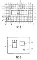
- the ray-tracing simulator 32 calculates (step 42) the expected received signal for a signal transmitted from the same radio station in each of a number of bins, i.e. areas 4, of building 2. That is to say, the amplitude, phase and delay of backscattered signal components 8 reflected from the signal 6 are calculated.
- the diagram shows a grid similar in size to the rooms, for clarity, a real grid may be on a much finer scale to allow more precise location.
- the grid may divide the building into square or rectangular areas with sides in the range 0.1m to 2m, preferably 0.5m to 1 m. Square grids may be most convenient in many situations.
- the simulator determines the amplitude, phase and delay of each expected reflected signal component returning to the radio receiver after being reflected off corresponding reflectors.
- the results of the calculations are then input into the first and second radio stations and stored as part of the parameter database 36 for that area 4 (step 46).
- information regarding the ten most significant (i.e. strongest) signal components 8 are stored, though this number may be varied as required.
- the radio station 10, 20 sends out (step 54) a location signal 6. This is scattered in the real building and reflected back-scattered components 8 are received back at the radio station 10 and picked up by the antenna 18, 28 (step 56), called a received signal.
- the radio station 10, 20 calculates the amplitude phase and delay of the received back-scattered components 8. This calculation may be done in any of a number of ways, for example using a maximum likelihood estimate.
- the amplitude, phase and delay of the back-scattered components 8 of the received signal are then compared (step 58) with the calculated values stored in the parameter database 36 to determine the best match.
- the area 4 corresponding to the best match is then taken to be the area 4 in which the radio station 10, 20 is located.
- One or both of the radio stations 10,20 can then send (step 60) information regarding its own location to the other.
- a longer wavelength signal is used to transmit this information than that used for position determination, since a longer wavelength signal is less susceptible to being absorbed by materials, other than metal reflectors, preventing any transmission of the line of sight signal.
- the radio stations 10, 20 are also able to build up an object database 37.
- the radio station 10, 20 is brought adjacent to an object and transmits a signal through the multiple antennas (step 48). This is then reflected off the object and a reflected signal received (step 50).
- the use of multiple antennas allows the reflected signal to represent not merely the reflectivity and distance of the object but also its size and shape.
- the user is prompted (step 51) to input the object name, and this is stored (step 52) in the object database together with the reflectivity size and shape information. Steps 48 to 52 are then repeated (step 53) to build up an object database 37 with information regarding multiple objects.
- the information is then used after the room information is determined to locate adjacent objects.
- the received signals received in step 56 are analysed for a best fit to adjacent objects.
- the features of the received signals are compared with those stored as the parameter data of the area that gives the best match.
- the differences will generally be caused by reflections of objects not in the building plan.
- the method includes (step 66) determining the differences between the features of the received signals with the features stored in the parameter database corresponding to the best match of the received signals with the parameter database, and then comparing (step 68) the differences with the objects stored in the object database to determine the size shape and distance to one or more nearby objects.
- the name of the best fit object can then be output (step 70).
- the first radio station 10 can be a mobile telephone and the second radio station 20 can be a set of door keys equipped with a transceiver key fob. If the keys become lost, a signal can be sent from the mobile telephone 10 to the door keys 20 to cause the door keys to operate the procedure above to locate local objects. This may determine, for example, that the door keys are in the bedroom 1m from a table 80 and 2m from a table lamp 82. This information can be transmitted to the mobile telephone and displayed to allow the user of the mobile telephone to find the door keys more easily.
- the differences between the calculated and measured data gives information about differences between the real environment and that in the building plans input at the start of the process to calculate the expected signals received.
- the differences and information about local objects can be stored in a map database 39 (step 72).
- the map database can then be used, for example, to determine both the room containing the door keys and the location of the door keys with respect to the objects in the room.
- the differences caused by moving objects such as people should in general not be included in the map database 39. This can be achieved by checking for motion of a particular reflector and not including data from moving reflectors in the map database. Alternatively, reflectors having a reflectivity and permitivity corresponding to humans or animals can be rejected.
- the object database is not built up experimentally but simply stored in the radio stations. Typical objects such as tables, chairs and floors can simply be included with typical parameters, or alternatively or additionally more specific objects known to be in the local environment can be included.
- the backscattered signal strength of the received signal as a function of time is measured. Therefore, in this embodiment, the calculation and storage steps 42,44 calculate the expected backscattered signal power as a function of time. The step of finding the best match then fits the received signal to the expected reflected signal power to find the best fit and hence the location of the radio station.
- the first radio station 10 is a static radio station at a known position.
- the second radio station 20 is a mobile station that obtains information about its location and objects in its vicinity and sends the information back to the first radio station 10.
- radio stations 10, 20 with multiple antennas use radio stations 10, 20 with multiple antennas
- the invention is also applicable to radio stations 10, 20 with single antennas. It is more difficult to determine the size and shape of objects but this may not be necessary in all applications.
- One way of obtaining more information using just a single antenna is to send radio signals of different frequencies. As will be appreciated by the skilled person, this approach can also be used with multiple antennas.
- the invention can also be used outdoors as well as indoors, especially where the outdoor environment is well mapped.
- the invention may have applications for games played using mobile radio transmitters that can use information about the location and velocity of the player to provide information to a game server and to the player.
Landscapes
- Physics & Mathematics (AREA)
- Engineering & Computer Science (AREA)
- General Physics & Mathematics (AREA)
- Radar, Positioning & Navigation (AREA)
- Remote Sensing (AREA)
- Position Fixing By Use Of Radio Waves (AREA)
- Radar Systems Or Details Thereof (AREA)
- Exposure Of Semiconductors, Excluding Electron Or Ion Beam Exposure (AREA)
- Vehicle Body Suspensions (AREA)
Claims (10)
- Positionierverfahren einer Funkstation (10, 20), das Verfahren umfassend:Bereitstellen einer Parameterdatenbank (36), welche erwartete Signalparameter der rückgestreuten Signale als eine Funktion der Position aufweist;Bereitstellen einer Objektdatenbank (37), welche erwartete Signalparameter der rückgestreuten Signale von mehreren Objekten aufweist;Übertragen eines Ortssignals (6) von der Funkstation, so dass es eine Mehrwegereflexion erfährt, bevor es an der Funkstation wieder als ein Empfangssignal (8) empfangen wird;Messen vorbestimmter Merkmale des empfangenen Signals;Vergleichen der vorbestimmten Merkmale des Empfangssignals mit den gespeicherten Daten in der Parameterdatenbank, um die beste Übereinstimmung und dementsprechend die Position der Funkstation zu finden;Identifizieren von Differenzen zwischen den vorbestimmten Merkmalen des Empfangssignals und denen, welche nach den gespeicherten Daten in der Parameterdatenbank erwartet werden; undVergleichen der Differenzen mit den gespeicherten Daten in der Objektdatenbank, um alle guten Übereinstimmungen zu finden und dementsprechend Objekte zu identifizieren, welche in der Nähe der Funkstation angeordnet sind.
- Verfahren nach Anspruch 1, wobei der Schritt des Bereitstellens einer Parameterdatenbank (36) Folgendes aufweist:Eingeben von Daten, welche ein Gebäude definieren;Aufteilen des Gebäudes in ein vorbestimmtes Gitter von Bereichen (4);Berechnen des erwarteten Empfangssignals, welches von einem Empfänger in jedem der Bereiche empfangen werden würde, wenn ein Ortssignal von einem Sender gesendet wird, welcher vorbestimmt entweder an dem Funkempfänger befestigt ist oder sich an einem vorbestimmten Ort befindet; undSpeichern deutlicher Merkmale der erwarteten Empfangssignale entsprechend jedes der Bereiche als Parameterdaten (36).
- Verfahren nach Anspruch 1 oder 2, wobei der Schritt des Bereitstellens einer Objektdatenbank (37) ein sequenzielles Lokalisieren der Funkstation in der Nähe zu mehreren Objekten, und für jedes Objekt ein Übertragen eines Signals, ein Empfangen eines rückgestreuten Signals, welches von dem Objekt reflektiert wurde, und ein Speichern der gemessenen vorbestimmten Parameter des empfangenen rückgestreuten Signals als Objektdaten für eine nachfolgende Verwendung in dem Schritt des Prüfens der vorbestimmten Merkmale des Empfangssignals gegen gespeicherte Objektparameterdaten aufweist.
- Verfahren nach einem der vorhergehenden Ansprüche, wobei:die vorbestimmten Merkmale die Amplitude, die Phase und die Verzögerung der Komponenten des Empfangssignals sind, welche am Empfänger gemessen werden; unddie Schritte des Vergleichens der vorbestimmten Merkmale und des Vergleichens der Differenzen die gemessenen Amplitude, Phase und Verzögerung mit den erwarteten Signalparametern vergleichen, um die beste Übereinstimmung zu finden.
- Verfahren nach einem der Ansprüche 1 bis 3, wobei die vorbestimmten Merkmale die Leistung des empfangenen Signals als eine Funktion der Zeit sind, welche ein Verzögerungsprofil bilden.
- Verfahren nach einem der vorhergehenden Ansprüche, wobei die Funkstation (10, 20) mehrere Antennen (18) aufweist und bei dem Schritt des Vergleichens der Differenzen zu den Informationen in der Objektdatenbank (37) die Differenzen analysiert werden, um Objekte in der Nähe der Funkstation (10, 20) und ihre Distanz zu bestimmen.
- Verfahren zum Lokalisieren einer ersten und einer zweiten Funkstation, umfassend:Finden der Position einer ersten Funkstation (10) unter Verwendung eines Verfahrens nach einem der Ansprüche 1 bis 6;Finden der Position einer zweiten Funkstation (20) unter Verwendung eines Verfahrens nach einem der Ansprüche 1 bis 6; undÜbertragen eines Funksignals, welches die Position der zweiten Funkstation repräsentiert, von der zweiten Funkstation an die erste Funkstation.
- Funkstation (10, 20) umfassend:mindestens eine Antenne (18, 28);einen Sendeempfänger (12, 22);einen Prozessor (14, 24); undeinen Speicher (16, 26), welcher eine Parameterdatenbank (36), welche erwartete Signalparameter der rückgestreuten Signale als eine Funktion der Position innerhalb des Gebäudes aufweist; und eine Objektdatenbank (37) speichert, welche erwartete Signalparameter der rückgestreuten Signale von mehreren Objekten aufweist;wobei der Speicher Code (30) aufweist, welcher eingerichtet ist, dass die Funkstation Folgendes ausführen:Übertragen eines Ortssignals aus der mindestens einen Antenne, so dass es eine Mehrwegereflexion erfährt, bevor es am Empfänger als ein Empfangssignal empfangen wird;Messen vorbestimmter Merkmale des empfangenen Signals;Vergleichen der vorbestimmten Merkmale mit den gespeicherten Daten in der Parameterdatenbank, um die beste Übereinstimmung und dementsprechend die Position der Funkstation zu finden;Identifizieren von Differenzen zwischen den vorbestimmten Merkmalen des Empfangssignals und denen, welche nach den gespeicherten Daten in der Parameterdatenbank erwartet werden; undVergleichen der Differenzen mit den gespeicherten Daten in der Objektdatenbank (37), um alle guten Übereinstimmungen zu finden und dementsprechend Objekte zu identifizieren, welche in der Nähe der Funkstation angeordnet sind.
- Funkstation nach Anspruch 8, umfassendmehrere Antennen (18, 28) zum gleichzeitigen Übertragen mehrerer Funksignale.
- Funksystem, umfassend mehrere Funkstationen (10, 20) nach Anspruch 9 oder 10, welche eingerichtet sind, um miteinander zu kommunizieren.
Applications Claiming Priority (3)
| Application Number | Priority Date | Filing Date | Title |
|---|---|---|---|
| GB0304861 | 2003-03-04 | ||
| GBGB0304861.8A GB0304861D0 (en) | 2003-03-04 | 2003-03-04 | Object location |
| PCT/IB2004/000558 WO2004079389A1 (en) | 2003-03-04 | 2004-02-20 | Object location |
Publications (2)
| Publication Number | Publication Date |
|---|---|
| EP1601988A1 EP1601988A1 (de) | 2005-12-07 |
| EP1601988B1 true EP1601988B1 (de) | 2007-04-18 |
Family
ID=9954041
Family Applications (1)
| Application Number | Title | Priority Date | Filing Date |
|---|---|---|---|
| EP04713143A Expired - Lifetime EP1601988B1 (de) | 2003-03-04 | 2004-02-20 | Objektpositionsbestimmung |
Country Status (10)
| Country | Link |
|---|---|
| US (1) | US20070099625A1 (de) |
| EP (1) | EP1601988B1 (de) |
| JP (1) | JP4667368B2 (de) |
| KR (1) | KR20050107482A (de) |
| CN (1) | CN100523861C (de) |
| AT (1) | ATE360219T1 (de) |
| DE (1) | DE602004005970T2 (de) |
| GB (1) | GB0304861D0 (de) |
| TW (1) | TW200501767A (de) |
| WO (1) | WO2004079389A1 (de) |
Families Citing this family (32)
| Publication number | Priority date | Publication date | Assignee | Title |
|---|---|---|---|---|
| US8018383B1 (en) * | 2010-06-08 | 2011-09-13 | Q-Track Corporation | Method and apparatus for determining location using signals-of-opportunity |
| US9285453B2 (en) | 2002-08-19 | 2016-03-15 | Q-Track Corporation | Method of near-field electromagnetic ranging and location |
| CN100368822C (zh) * | 2005-12-05 | 2008-02-13 | 国家无线电监测中心 | 无线电发射源定位方法与系统 |
| US7764230B2 (en) * | 2007-03-13 | 2010-07-27 | Alcatel-Lucent Usa Inc. | Methods for locating transmitters using backward ray tracing |
| US8583079B2 (en) | 2007-08-14 | 2013-11-12 | Mpanion, Inc. | Rich presence status based on location, activity, availability and transit status of a user |
| US8050690B2 (en) | 2007-08-14 | 2011-11-01 | Mpanion, Inc. | Location based presence and privacy management |
| US8489111B2 (en) | 2007-08-14 | 2013-07-16 | Mpanion, Inc. | Real-time location and presence using a push-location client and server |
| US12439340B2 (en) | 2007-08-14 | 2025-10-07 | Mpanion, Inc. | Real-time location and presence using a push-location client and server |
| JP2009216529A (ja) * | 2008-03-11 | 2009-09-24 | Japan Radio Co Ltd | 位相ずれ算出装置及び測位装置 |
| US20130293396A1 (en) | 2008-03-15 | 2013-11-07 | James R. Selevan | Sequenced guiding systems for vehicles and pedestrians |
| CN101394672B (zh) * | 2008-10-30 | 2012-08-29 | 上海大学 | 基于多径散射信息的高精度无线定位方法及系统 |
| US8170815B2 (en) * | 2009-06-08 | 2012-05-01 | Rockstar Bidco Lp | RF fingerprinting for location estimation |
| FR2969819A1 (fr) * | 2010-12-22 | 2012-06-29 | St Microelectronics Grenoble 2 | Capteur d'image tridimensionnel |
| TWI418834B (zh) * | 2011-03-03 | 2013-12-11 | Univ Shu Te | Scanning positioning system |
| WO2012143952A2 (en) * | 2011-04-20 | 2012-10-26 | B Amutha | A system and apparatus for safe remote on-line tracing, shadowing, surveillance, inter-communication, location, navigation, tagging, rescue, recovery and restitution of humans and stolen/missing chattels, and the method/s thereof |
| US9185528B2 (en) * | 2012-06-28 | 2015-11-10 | Northrop Grumman Systems Corporation | WiFi mapping and motion detection |
| US9288088B1 (en) * | 2013-02-22 | 2016-03-15 | Pi Variables, Inc. | Synchronizing the behavior of discrete digital devices |
| US11313546B2 (en) | 2014-11-15 | 2022-04-26 | James R. Selevan | Sequential and coordinated flashing of electronic roadside flares with active energy conservation |
| US9835319B2 (en) | 2014-11-15 | 2017-12-05 | James R. Selevan | Sequential and coordinated flashing of electronic roadside flares with active energy conservation |
| KR102402743B1 (ko) * | 2015-05-27 | 2022-05-27 | 삼성전자주식회사 | 위치 측정 방법 및 전자장치 |
| JP6396355B2 (ja) * | 2016-03-29 | 2018-09-26 | セコム株式会社 | 端末所持者検知システム |
| US10551014B2 (en) | 2017-02-10 | 2020-02-04 | James R. Selevan | Portable electronic flare carrying case and system |
| USD854438S1 (en) | 2017-02-10 | 2019-07-23 | Pi Variables, Inc. | Portable electronic flare |
| US11725785B2 (en) | 2017-02-10 | 2023-08-15 | James R. Selevan | Portable electronic flare carrying case and system |
| USD854437S1 (en) | 2017-02-10 | 2019-07-23 | Pi Variables, Inc. | Portable electronic flare system |
| AU2018297199B2 (en) | 2017-07-06 | 2023-12-07 | Adam Jordan Selevan | Devices and methods for synchronized signaling of the positions of moving pedestrians or vehicles |
| CN110687503B (zh) * | 2019-10-31 | 2021-07-09 | 华中科技大学 | 一种基于背向散射的无线定位方法、装置及系统 |
| CN110958065B (zh) * | 2019-12-03 | 2022-04-08 | 中国电子科技集团公司第五十四研究所 | 一种散射接收信号功率检测方法 |
| US20230296722A1 (en) * | 2020-07-31 | 2023-09-21 | Telefonaktiebolaget Lm Ericsson (Publ) | Tools and methods for ue environment mapping |
| JP2023545618A (ja) * | 2020-09-09 | 2023-10-31 | オランジュ | 対象物を位置特定する方法 |
| US12277845B2 (en) | 2021-12-29 | 2025-04-15 | Adam Jordan Selevan | Vehicular incursion alert systems and methods |
| EP4476706A4 (de) | 2022-02-11 | 2026-03-11 | Daniel Joseph Selevan | Netzwerkfähige vorrichtungen zur internen beleuchtung von verkehrskegeln und anderen verkehrskanalisierungsvorrichtungen |
Family Cites Families (13)
| Publication number | Priority date | Publication date | Assignee | Title |
|---|---|---|---|---|
| US5491644A (en) * | 1993-09-07 | 1996-02-13 | Georgia Tech Research Corporation | Cell engineering tool and methods |
| GB2311697B (en) * | 1996-03-22 | 1999-07-28 | Matsushita Electric Industrial Co Ltd | Wireless communication system and method and system for detection of position of radio mobile station |
| SE509733C2 (sv) * | 1996-07-05 | 1999-03-01 | Foersvarets Forskningsanstalt | Sätt att detektera och klassificera objekt med hjälp av radar |
| US6249252B1 (en) * | 1996-09-09 | 2001-06-19 | Tracbeam Llc | Wireless location using multiple location estimators |
| US6026304A (en) * | 1997-01-08 | 2000-02-15 | U.S. Wireless Corporation | Radio transmitter location finding for wireless communication network services and management |
| FI105384B (fi) * | 1997-10-03 | 2000-07-31 | Nokia Networks Oy | Menetelmä päätelaitteen sijainnin määrittämiseksi ja solukkoradiojärjestelmä |
| US6161018A (en) * | 1998-02-27 | 2000-12-12 | Motorola, Inc. | Method and system for estimating a subscriber's location in a wireless communication system service area |
| US6393294B1 (en) * | 1998-09-22 | 2002-05-21 | Polaris Wireless, Inc. | Location determination using RF fingerprinting |
| EP1058855A4 (de) * | 1998-12-04 | 2004-09-01 | Trafficmaster Usa Inc | Funkstanortsbestimmung mittels räumlicher signaturinformation |
| US6446031B1 (en) * | 1999-01-22 | 2002-09-03 | The University Of Akron | Cone mapping physical optics for design of indoor communication system |
| JP3648140B2 (ja) * | 2000-08-21 | 2005-05-18 | 株式会社アドバンテスト | 電波監視方法及び装置 |
| ITTO20010486A1 (it) * | 2001-05-23 | 2002-11-23 | Telecom Italia Lab Spa | Procedimento per la localizzazione di terminali nell'ambito di reti di comunicazione, relativo sistema e terminale. |
| US6522296B2 (en) * | 2001-06-25 | 2003-02-18 | Harris Corporation | Method and system for calibrating wireless location systems |
-
2003
- 2003-03-04 GB GBGB0304861.8A patent/GB0304861D0/en not_active Ceased
-
2004
- 2004-02-20 CN CNB2004800058596A patent/CN100523861C/zh not_active Expired - Fee Related
- 2004-02-20 US US10/547,627 patent/US20070099625A1/en not_active Abandoned
- 2004-02-20 WO PCT/IB2004/000558 patent/WO2004079389A1/en not_active Ceased
- 2004-02-20 EP EP04713143A patent/EP1601988B1/de not_active Expired - Lifetime
- 2004-02-20 KR KR1020057016294A patent/KR20050107482A/ko not_active Withdrawn
- 2004-02-20 DE DE602004005970T patent/DE602004005970T2/de not_active Expired - Lifetime
- 2004-02-20 JP JP2006506279A patent/JP4667368B2/ja not_active Expired - Fee Related
- 2004-02-20 AT AT04713143T patent/ATE360219T1/de not_active IP Right Cessation
- 2004-03-01 TW TW093105296A patent/TW200501767A/zh unknown
Also Published As
| Publication number | Publication date |
|---|---|
| CN100523861C (zh) | 2009-08-05 |
| GB0304861D0 (en) | 2003-04-09 |
| EP1601988A1 (de) | 2005-12-07 |
| TW200501767A (en) | 2005-01-01 |
| KR20050107482A (ko) | 2005-11-11 |
| WO2004079389A1 (en) | 2004-09-16 |
| DE602004005970T2 (de) | 2008-01-17 |
| CN1756964A (zh) | 2006-04-05 |
| US20070099625A1 (en) | 2007-05-03 |
| JP4667368B2 (ja) | 2011-04-13 |
| DE602004005970D1 (de) | 2007-05-31 |
| JP2006519389A (ja) | 2006-08-24 |
| ATE360219T1 (de) | 2007-05-15 |
Similar Documents
| Publication | Publication Date | Title |
|---|---|---|
| EP1601988B1 (de) | Objektpositionsbestimmung | |
| CN101625406B (zh) | 测位系统、测位方法 | |
| Kotanen et al. | Experiments on local positioning with Bluetooth | |
| US7773995B2 (en) | Method and apparatus for utilizing RF signals to create a site specific representation of an environment | |
| EP2270536B1 (de) | Vorrichtung zur Schätzung der Gebäudeeinwirkung und Verfahren zur Schätzung der Bauwerkseinwirkung | |
| Tarrío et al. | A new positioning technique for RSS-based localization based on a weighted least squares estimator | |
| US20060114104A1 (en) | RFID reader management system and method | |
| EP3354086B1 (de) | Ortung einer mobilen vorrichtung | |
| Kanhere et al. | Calibration of NYURay for ray tracing using 28, 73, and 142 GHz channel measurements conducted in indoor, outdoor, and factory scenarios | |
| US12196876B2 (en) | Likelihood-based acoustic positioning | |
| US10547964B2 (en) | Method and device for estimating accuracy of a position determination | |
| Zhao et al. | VIRE: Virtual Reference Elimination for Active RFID-based Localization. | |
| Ivanov et al. | Automatic WLAN localization for industrial automation | |
| CA2446842A1 (en) | Synthetic doppler system and method for locating cooperative transceivers | |
| Drozd et al. | Evaluation of the cost-effective indoor wireless positioning system using RSSI method | |
| Kaya et al. | Emitter localization and visualization (ELVIS): A backward ray tracing algorithm for locating emitters | |
| CN101288002A (zh) | 用于利用rf信号创建特定地点环境表示的方法和装置 | |
| US20050176443A1 (en) | Cellular phone geolocation system | |
| Basheer et al. | R-factor: A new parameter to enhance location accuracy in rssi based real-time location systems | |
| Taylor | Received signal strength-based localization of non-collaborative emitters in the presence of correlated shadowing | |
| Huszák et al. | Investigation of wlan access point placement for indoor positioning | |
| Abbas et al. | Estimating of target coordinates based on Trilateration technique for indoor localization. | |
| Hatthasin et al. | One base station approach for indoor geolocation system using RFID | |
| KR102778089B1 (ko) | 위치 측정 방법 및 장치 | |
| Chatterjee et al. | Non cooperative primary users-localization in cognitive radio networks |
Legal Events
| Date | Code | Title | Description |
|---|---|---|---|
| PUAI | Public reference made under article 153(3) epc to a published international application that has entered the european phase |
Free format text: ORIGINAL CODE: 0009012 |
|
| 17P | Request for examination filed |
Effective date: 20051004 |
|
| AK | Designated contracting states |
Kind code of ref document: A1 Designated state(s): AT BE BG CH CY CZ DE DK EE ES FI FR GB GR HU IE IT LI LU MC NL PT RO SE SI SK TR |
|
| AX | Request for extension of the european patent |
Extension state: AL LT LV MK |
|
| DAX | Request for extension of the european patent (deleted) | ||
| GRAP | Despatch of communication of intention to grant a patent |
Free format text: ORIGINAL CODE: EPIDOSNIGR1 |
|
| GRAS | Grant fee paid |
Free format text: ORIGINAL CODE: EPIDOSNIGR3 |
|
| GRAA | (expected) grant |
Free format text: ORIGINAL CODE: 0009210 |
|
| AK | Designated contracting states |
Kind code of ref document: B1 Designated state(s): AT BE BG CH CY CZ DE DK EE ES FI FR GB GR HU IE IT LI LU MC NL PT RO SE SI SK TR |
|
| PG25 | Lapsed in a contracting state [announced via postgrant information from national office to epo] |
Ref country code: LI Free format text: LAPSE BECAUSE OF FAILURE TO SUBMIT A TRANSLATION OF THE DESCRIPTION OR TO PAY THE FEE WITHIN THE PRESCRIBED TIME-LIMIT Effective date: 20070418 Ref country code: CH Free format text: LAPSE BECAUSE OF FAILURE TO SUBMIT A TRANSLATION OF THE DESCRIPTION OR TO PAY THE FEE WITHIN THE PRESCRIBED TIME-LIMIT Effective date: 20070418 Ref country code: FI Free format text: LAPSE BECAUSE OF FAILURE TO SUBMIT A TRANSLATION OF THE DESCRIPTION OR TO PAY THE FEE WITHIN THE PRESCRIBED TIME-LIMIT Effective date: 20070418 Ref country code: SI Free format text: LAPSE BECAUSE OF FAILURE TO SUBMIT A TRANSLATION OF THE DESCRIPTION OR TO PAY THE FEE WITHIN THE PRESCRIBED TIME-LIMIT Effective date: 20070418 |
|
| REG | Reference to a national code |
Ref country code: CH Ref legal event code: EP |
|
| REG | Reference to a national code |
Ref country code: IE Ref legal event code: FG4D |
|
| REF | Corresponds to: |
Ref document number: 602004005970 Country of ref document: DE Date of ref document: 20070531 Kind code of ref document: P |
|
| PG25 | Lapsed in a contracting state [announced via postgrant information from national office to epo] |
Ref country code: SE Free format text: LAPSE BECAUSE OF FAILURE TO SUBMIT A TRANSLATION OF THE DESCRIPTION OR TO PAY THE FEE WITHIN THE PRESCRIBED TIME-LIMIT Effective date: 20070718 |
|
| PG25 | Lapsed in a contracting state [announced via postgrant information from national office to epo] |
Ref country code: ES Free format text: LAPSE BECAUSE OF FAILURE TO SUBMIT A TRANSLATION OF THE DESCRIPTION OR TO PAY THE FEE WITHIN THE PRESCRIBED TIME-LIMIT Effective date: 20070729 |
|
| PG25 | Lapsed in a contracting state [announced via postgrant information from national office to epo] |
Ref country code: PT Free format text: LAPSE BECAUSE OF FAILURE TO SUBMIT A TRANSLATION OF THE DESCRIPTION OR TO PAY THE FEE WITHIN THE PRESCRIBED TIME-LIMIT Effective date: 20070918 |
|
| ET | Fr: translation filed | ||
| REG | Reference to a national code |
Ref country code: CH Ref legal event code: PL |
|
| NLV1 | Nl: lapsed or annulled due to failure to fulfill the requirements of art. 29p and 29m of the patents act | ||
| PG25 | Lapsed in a contracting state [announced via postgrant information from national office to epo] |
Ref country code: AT Free format text: LAPSE BECAUSE OF FAILURE TO SUBMIT A TRANSLATION OF THE DESCRIPTION OR TO PAY THE FEE WITHIN THE PRESCRIBED TIME-LIMIT Effective date: 20070418 |
|
| PG25 | Lapsed in a contracting state [announced via postgrant information from national office to epo] |
Ref country code: BE Free format text: LAPSE BECAUSE OF FAILURE TO SUBMIT A TRANSLATION OF THE DESCRIPTION OR TO PAY THE FEE WITHIN THE PRESCRIBED TIME-LIMIT Effective date: 20070418 |
|
| PG25 | Lapsed in a contracting state [announced via postgrant information from national office to epo] |
Ref country code: BG Free format text: LAPSE BECAUSE OF FAILURE TO SUBMIT A TRANSLATION OF THE DESCRIPTION OR TO PAY THE FEE WITHIN THE PRESCRIBED TIME-LIMIT Effective date: 20070718 Ref country code: CZ Free format text: LAPSE BECAUSE OF FAILURE TO SUBMIT A TRANSLATION OF THE DESCRIPTION OR TO PAY THE FEE WITHIN THE PRESCRIBED TIME-LIMIT Effective date: 20070418 Ref country code: DK Free format text: LAPSE BECAUSE OF FAILURE TO SUBMIT A TRANSLATION OF THE DESCRIPTION OR TO PAY THE FEE WITHIN THE PRESCRIBED TIME-LIMIT Effective date: 20070418 Ref country code: NL Free format text: LAPSE BECAUSE OF FAILURE TO SUBMIT A TRANSLATION OF THE DESCRIPTION OR TO PAY THE FEE WITHIN THE PRESCRIBED TIME-LIMIT Effective date: 20070418 |
|
| PLBE | No opposition filed within time limit |
Free format text: ORIGINAL CODE: 0009261 |
|
| STAA | Information on the status of an ep patent application or granted ep patent |
Free format text: STATUS: NO OPPOSITION FILED WITHIN TIME LIMIT |
|
| PG25 | Lapsed in a contracting state [announced via postgrant information from national office to epo] |
Ref country code: SK Free format text: LAPSE BECAUSE OF FAILURE TO SUBMIT A TRANSLATION OF THE DESCRIPTION OR TO PAY THE FEE WITHIN THE PRESCRIBED TIME-LIMIT Effective date: 20070418 |
|
| 26N | No opposition filed |
Effective date: 20080121 |
|
| PG25 | Lapsed in a contracting state [announced via postgrant information from national office to epo] |
Ref country code: IT Free format text: LAPSE BECAUSE OF FAILURE TO SUBMIT A TRANSLATION OF THE DESCRIPTION OR TO PAY THE FEE WITHIN THE PRESCRIBED TIME-LIMIT Effective date: 20070418 Ref country code: GR Free format text: LAPSE BECAUSE OF FAILURE TO SUBMIT A TRANSLATION OF THE DESCRIPTION OR TO PAY THE FEE WITHIN THE PRESCRIBED TIME-LIMIT Effective date: 20070719 |
|
| PG25 | Lapsed in a contracting state [announced via postgrant information from national office to epo] |
Ref country code: RO Free format text: LAPSE BECAUSE OF FAILURE TO SUBMIT A TRANSLATION OF THE DESCRIPTION OR TO PAY THE FEE WITHIN THE PRESCRIBED TIME-LIMIT Effective date: 20070418 |
|
| PG25 | Lapsed in a contracting state [announced via postgrant information from national office to epo] |
Ref country code: MC Free format text: LAPSE BECAUSE OF NON-PAYMENT OF DUE FEES Effective date: 20080228 |
|
| PG25 | Lapsed in a contracting state [announced via postgrant information from national office to epo] |
Ref country code: IE Free format text: LAPSE BECAUSE OF NON-PAYMENT OF DUE FEES Effective date: 20080220 Ref country code: EE Free format text: LAPSE BECAUSE OF FAILURE TO SUBMIT A TRANSLATION OF THE DESCRIPTION OR TO PAY THE FEE WITHIN THE PRESCRIBED TIME-LIMIT Effective date: 20070418 |
|
| PG25 | Lapsed in a contracting state [announced via postgrant information from national office to epo] |
Ref country code: CY Free format text: LAPSE BECAUSE OF FAILURE TO SUBMIT A TRANSLATION OF THE DESCRIPTION OR TO PAY THE FEE WITHIN THE PRESCRIBED TIME-LIMIT Effective date: 20070418 |
|
| PG25 | Lapsed in a contracting state [announced via postgrant information from national office to epo] |
Ref country code: LU Free format text: LAPSE BECAUSE OF NON-PAYMENT OF DUE FEES Effective date: 20080220 Ref country code: HU Free format text: LAPSE BECAUSE OF FAILURE TO SUBMIT A TRANSLATION OF THE DESCRIPTION OR TO PAY THE FEE WITHIN THE PRESCRIBED TIME-LIMIT Effective date: 20071019 |
|
| PG25 | Lapsed in a contracting state [announced via postgrant information from national office to epo] |
Ref country code: TR Free format text: LAPSE BECAUSE OF FAILURE TO SUBMIT A TRANSLATION OF THE DESCRIPTION OR TO PAY THE FEE WITHIN THE PRESCRIBED TIME-LIMIT Effective date: 20070418 |
|
| PGFP | Annual fee paid to national office [announced via postgrant information from national office to epo] |
Ref country code: FR Payment date: 20120312 Year of fee payment: 9 |
|
| PGFP | Annual fee paid to national office [announced via postgrant information from national office to epo] |
Ref country code: GB Payment date: 20120229 Year of fee payment: 9 |
|
| PGFP | Annual fee paid to national office [announced via postgrant information from national office to epo] |
Ref country code: DE Payment date: 20120430 Year of fee payment: 9 |
|
| GBPC | Gb: european patent ceased through non-payment of renewal fee |
Effective date: 20130220 |
|
| REG | Reference to a national code |
Ref country code: FR Ref legal event code: ST Effective date: 20131031 |
|
| REG | Reference to a national code |
Ref country code: DE Ref legal event code: R119 Ref document number: 602004005970 Country of ref document: DE Effective date: 20130903 |
|
| PG25 | Lapsed in a contracting state [announced via postgrant information from national office to epo] |
Ref country code: DE Free format text: LAPSE BECAUSE OF NON-PAYMENT OF DUE FEES Effective date: 20130903 Ref country code: GB Free format text: LAPSE BECAUSE OF NON-PAYMENT OF DUE FEES Effective date: 20130220 Ref country code: FR Free format text: LAPSE BECAUSE OF NON-PAYMENT OF DUE FEES Effective date: 20130228 |