EP1601874B1 - Intergrierte mikrofluidische kontrollvorrichtung mit programmierbaren taktilen stellgliedern - Google Patents
Intergrierte mikrofluidische kontrollvorrichtung mit programmierbaren taktilen stellgliedern Download PDFInfo
- Publication number
- EP1601874B1 EP1601874B1 EP04719255A EP04719255A EP1601874B1 EP 1601874 B1 EP1601874 B1 EP 1601874B1 EP 04719255 A EP04719255 A EP 04719255A EP 04719255 A EP04719255 A EP 04719255A EP 1601874 B1 EP1601874 B1 EP 1601874B1
- Authority
- EP
- European Patent Office
- Prior art keywords
- fluid
- flow channel
- tactile actuator
- channel
- protrusions
- Prior art date
- Legal status (The legal status is an assumption and is not a legal conclusion. Google has not performed a legal analysis and makes no representation as to the accuracy of the status listed.)
- Expired - Lifetime
Links
- 230000002572 peristaltic effect Effects 0.000 claims abstract description 9
- 239000012530 fluid Substances 0.000 claims description 51
- 238000000034 method Methods 0.000 claims description 26
- 230000012010 growth Effects 0.000 claims description 18
- 239000000758 substrate Substances 0.000 claims description 18
- 238000005086 pumping Methods 0.000 claims description 17
- 229920001971 elastomer Polymers 0.000 claims description 9
- 238000004891 communication Methods 0.000 claims description 8
- 239000000806 elastomer Substances 0.000 claims description 8
- 230000008569 process Effects 0.000 claims description 8
- 239000013536 elastomeric material Substances 0.000 claims description 5
- 239000007788 liquid Substances 0.000 claims description 4
- 238000004590 computer program Methods 0.000 claims description 2
- 239000000203 mixture Substances 0.000 claims description 2
- 229920002379 silicone rubber Polymers 0.000 claims description 2
- 239000001963 growth medium Substances 0.000 claims 1
- 239000002243 precursor Substances 0.000 claims 1
- 239000012528 membrane Substances 0.000 abstract description 9
- 238000002156 mixing Methods 0.000 abstract description 8
- 210000004027 cell Anatomy 0.000 description 41
- 239000010410 layer Substances 0.000 description 20
- 229920002120 photoresistant polymer Polymers 0.000 description 16
- 229920000435 poly(dimethylsiloxane) Polymers 0.000 description 16
- 239000011521 glass Substances 0.000 description 10
- 230000009471 action Effects 0.000 description 9
- 229920001486 SU-8 photoresist Polymers 0.000 description 7
- 239000002184 metal Substances 0.000 description 7
- 229910052751 metal Inorganic materials 0.000 description 7
- 235000015097 nutrients Nutrition 0.000 description 7
- 239000012190 activator Substances 0.000 description 6
- 238000010276 construction Methods 0.000 description 6
- 239000000499 gel Substances 0.000 description 6
- 210000001161 mammalian embryo Anatomy 0.000 description 6
- VYPSYNLAJGMNEJ-UHFFFAOYSA-N Silicium dioxide Chemical compound O=[Si]=O VYPSYNLAJGMNEJ-UHFFFAOYSA-N 0.000 description 5
- 238000010899 nucleation Methods 0.000 description 5
- 229920001296 polysiloxane Polymers 0.000 description 5
- -1 Poly(dimethylsiloxane) Polymers 0.000 description 4
- 238000004113 cell culture Methods 0.000 description 4
- 230000008859 change Effects 0.000 description 4
- 238000001514 detection method Methods 0.000 description 4
- 230000006870 function Effects 0.000 description 4
- 238000004519 manufacturing process Methods 0.000 description 4
- 229920003023 plastic Polymers 0.000 description 4
- 239000004033 plastic Substances 0.000 description 4
- 239000000126 substance Substances 0.000 description 4
- 230000004913 activation Effects 0.000 description 3
- 230000010261 cell growth Effects 0.000 description 3
- LOKCTEFSRHRXRJ-UHFFFAOYSA-I dipotassium trisodium dihydrogen phosphate hydrogen phosphate dichloride Chemical compound P(=O)(O)(O)[O-].[K+].P(=O)(O)([O-])[O-].[Na+].[Na+].[Cl-].[K+].[Cl-].[Na+] LOKCTEFSRHRXRJ-UHFFFAOYSA-I 0.000 description 3
- 239000003102 growth factor Substances 0.000 description 3
- 239000000463 material Substances 0.000 description 3
- 230000003287 optical effect Effects 0.000 description 3
- 239000002245 particle Substances 0.000 description 3
- 239000002953 phosphate buffered saline Substances 0.000 description 3
- 239000000243 solution Substances 0.000 description 3
- 238000004528 spin coating Methods 0.000 description 3
- 235000012431 wafers Nutrition 0.000 description 3
- 108091003079 Bovine Serum Albumin Proteins 0.000 description 2
- 239000006144 Dulbecco’s modified Eagle's medium Substances 0.000 description 2
- 238000003491 array Methods 0.000 description 2
- 238000003556 assay Methods 0.000 description 2
- 230000008901 benefit Effects 0.000 description 2
- 230000033228 biological regulation Effects 0.000 description 2
- 238000005266 casting Methods 0.000 description 2
- 230000001413 cellular effect Effects 0.000 description 2
- 230000004087 circulation Effects 0.000 description 2
- 239000011248 coating agent Substances 0.000 description 2
- 238000000576 coating method Methods 0.000 description 2
- 238000007796 conventional method Methods 0.000 description 2
- 238000013461 design Methods 0.000 description 2
- 239000000975 dye Substances 0.000 description 2
- 210000002257 embryonic structure Anatomy 0.000 description 2
- 239000012091 fetal bovine serum Substances 0.000 description 2
- 239000007789 gas Substances 0.000 description 2
- 230000005484 gravity Effects 0.000 description 2
- 230000001771 impaired effect Effects 0.000 description 2
- 238000001727 in vivo Methods 0.000 description 2
- 238000001459 lithography Methods 0.000 description 2
- 230000007246 mechanism Effects 0.000 description 2
- 244000005700 microbiome Species 0.000 description 2
- 238000000465 moulding Methods 0.000 description 2
- 210000003098 myoblast Anatomy 0.000 description 2
- 230000003647 oxidation Effects 0.000 description 2
- 238000007254 oxidation reaction Methods 0.000 description 2
- 238000000206 photolithography Methods 0.000 description 2
- BASFCYQUMIYNBI-UHFFFAOYSA-N platinum Chemical compound [Pt] BASFCYQUMIYNBI-UHFFFAOYSA-N 0.000 description 2
- 230000035755 proliferation Effects 0.000 description 2
- 230000001105 regulatory effect Effects 0.000 description 2
- 239000000565 sealant Substances 0.000 description 2
- 239000000377 silicon dioxide Substances 0.000 description 2
- 239000002356 single layer Substances 0.000 description 2
- 238000002174 soft lithography Methods 0.000 description 2
- UCSJYZPVAKXKNQ-HZYVHMACSA-N streptomycin Chemical compound CN[C@H]1[C@H](O)[C@@H](O)[C@H](CO)O[C@H]1O[C@@H]1[C@](C=O)(O)[C@H](C)O[C@H]1O[C@@H]1[C@@H](NC(N)=N)[C@H](O)[C@@H](NC(N)=N)[C@H](O)[C@H]1O UCSJYZPVAKXKNQ-HZYVHMACSA-N 0.000 description 2
- 230000000007 visual effect Effects 0.000 description 2
- 241000894006 Bacteria Species 0.000 description 1
- 229910001369 Brass Inorganic materials 0.000 description 1
- 206010010071 Coma Diseases 0.000 description 1
- 241000195493 Cryptophyta Species 0.000 description 1
- KCXVZYZYPLLWCC-UHFFFAOYSA-N EDTA Chemical compound OC(=O)CN(CC(O)=O)CCN(CC(O)=O)CC(O)=O KCXVZYZYPLLWCC-UHFFFAOYSA-N 0.000 description 1
- 241000233866 Fungi Species 0.000 description 1
- 229930182555 Penicillin Natural products 0.000 description 1
- JGSARLDLIJGVTE-MBNYWOFBSA-N Penicillin G Chemical compound N([C@H]1[C@H]2SC([C@@H](N2C1=O)C(O)=O)(C)C)C(=O)CC1=CC=CC=C1 JGSARLDLIJGVTE-MBNYWOFBSA-N 0.000 description 1
- 240000004808 Saccharomyces cerevisiae Species 0.000 description 1
- 102000004142 Trypsin Human genes 0.000 description 1
- 108090000631 Trypsin Proteins 0.000 description 1
- 241000251539 Vertebrata <Metazoa> Species 0.000 description 1
- 229920006266 Vinyl film Polymers 0.000 description 1
- 241000700605 Viruses Species 0.000 description 1
- 238000010521 absorption reaction Methods 0.000 description 1
- 230000004075 alteration Effects 0.000 description 1
- 238000004458 analytical method Methods 0.000 description 1
- 230000006907 apoptotic process Effects 0.000 description 1
- 238000013459 approach Methods 0.000 description 1
- 238000000429 assembly Methods 0.000 description 1
- 230000000712 assembly Effects 0.000 description 1
- QVGXLLKOCUKJST-UHFFFAOYSA-N atomic oxygen Chemical compound [O] QVGXLLKOCUKJST-UHFFFAOYSA-N 0.000 description 1
- 239000005388 borosilicate glass Substances 0.000 description 1
- 239000010951 brass Substances 0.000 description 1
- 238000000423 cell based assay Methods 0.000 description 1
- 239000006143 cell culture medium Substances 0.000 description 1
- 230000030833 cell death Effects 0.000 description 1
- 239000000919 ceramic Substances 0.000 description 1
- 239000003153 chemical reaction reagent Substances 0.000 description 1
- 239000003795 chemical substances by application Substances 0.000 description 1
- 239000002131 composite material Substances 0.000 description 1
- 230000006835 compression Effects 0.000 description 1
- 238000007906 compression Methods 0.000 description 1
- 239000002322 conducting polymer Substances 0.000 description 1
- 229920001940 conductive polymer Polymers 0.000 description 1
- 238000011109 contamination Methods 0.000 description 1
- 239000006059 cover glass Substances 0.000 description 1
- 230000001351 cycling effect Effects 0.000 description 1
- 230000003247 decreasing effect Effects 0.000 description 1
- 238000011161 development Methods 0.000 description 1
- 238000006073 displacement reaction Methods 0.000 description 1
- 239000012153 distilled water Substances 0.000 description 1
- 231100000673 dose–response relationship Toxicity 0.000 description 1
- 230000009977 dual effect Effects 0.000 description 1
- 239000013013 elastic material Substances 0.000 description 1
- 238000005516 engineering process Methods 0.000 description 1
- 238000002474 experimental method Methods 0.000 description 1
- 238000007687 exposure technique Methods 0.000 description 1
- 238000000684 flow cytometry Methods 0.000 description 1
- 239000007850 fluorescent dye Substances 0.000 description 1
- 239000011888 foil Substances 0.000 description 1
- 235000002864 food coloring agent Nutrition 0.000 description 1
- 239000003966 growth inhibitor Substances 0.000 description 1
- 230000005660 hydrophilic surface Effects 0.000 description 1
- 230000002706 hydrostatic effect Effects 0.000 description 1
- 230000006872 improvement Effects 0.000 description 1
- 238000011065 in-situ storage Methods 0.000 description 1
- 238000011534 incubation Methods 0.000 description 1
- 238000002347 injection Methods 0.000 description 1
- 239000007924 injection Substances 0.000 description 1
- 238000001746 injection moulding Methods 0.000 description 1
- 230000010354 integration Effects 0.000 description 1
- 238000002032 lab-on-a-chip Methods 0.000 description 1
- 238000000608 laser ablation Methods 0.000 description 1
- 230000033001 locomotion Effects 0.000 description 1
- 210000004962 mammalian cell Anatomy 0.000 description 1
- 238000005259 measurement Methods 0.000 description 1
- 238000002844 melting Methods 0.000 description 1
- 230000008018 melting Effects 0.000 description 1
- 210000002901 mesenchymal stem cell Anatomy 0.000 description 1
- 230000004089 microcirculation Effects 0.000 description 1
- 239000013307 optical fiber Substances 0.000 description 1
- 238000000399 optical microscopy Methods 0.000 description 1
- 239000001301 oxygen Substances 0.000 description 1
- 229910052760 oxygen Inorganic materials 0.000 description 1
- 238000000059 patterning Methods 0.000 description 1
- 230000000149 penetrating effect Effects 0.000 description 1
- 229940049954 penicillin Drugs 0.000 description 1
- 230000000737 periodic effect Effects 0.000 description 1
- 238000001020 plasma etching Methods 0.000 description 1
- 229910052697 platinum Inorganic materials 0.000 description 1
- 229920002401 polyacrylamide Polymers 0.000 description 1
- 238000006116 polymerization reaction Methods 0.000 description 1
- 230000009467 reduction Effects 0.000 description 1
- 238000011160 research Methods 0.000 description 1
- 239000011347 resin Substances 0.000 description 1
- 229920005989 resin Polymers 0.000 description 1
- 230000004044 response Effects 0.000 description 1
- 230000002441 reversible effect Effects 0.000 description 1
- 239000000523 sample Substances 0.000 description 1
- 229920006298 saran Polymers 0.000 description 1
- 238000007789 sealing Methods 0.000 description 1
- 210000002966 serum Anatomy 0.000 description 1
- 229910001285 shape-memory alloy Inorganic materials 0.000 description 1
- 230000011664 signaling Effects 0.000 description 1
- 239000010703 silicon Substances 0.000 description 1
- 229910052710 silicon Inorganic materials 0.000 description 1
- 229920006268 silicone film Polymers 0.000 description 1
- 238000004088 simulation Methods 0.000 description 1
- 229960005322 streptomycin Drugs 0.000 description 1
- 229920001187 thermosetting polymer Polymers 0.000 description 1
- 231100000027 toxicology Toxicity 0.000 description 1
- 238000012546 transfer Methods 0.000 description 1
- 239000012588 trypsin Substances 0.000 description 1
- 238000011144 upstream manufacturing Methods 0.000 description 1
- 238000012800 visualization Methods 0.000 description 1
- 235000013343 vitamin Nutrition 0.000 description 1
- 239000011782 vitamin Substances 0.000 description 1
- 229940088594 vitamin Drugs 0.000 description 1
- 229930003231 vitamin Natural products 0.000 description 1
- 239000011800 void material Substances 0.000 description 1
- 239000002699 waste material Substances 0.000 description 1
- XLYOFNOQVPJJNP-UHFFFAOYSA-N water Chemical compound O XLYOFNOQVPJJNP-UHFFFAOYSA-N 0.000 description 1
Images

Classifications
-
- B—PERFORMING OPERATIONS; TRANSPORTING
- B01—PHYSICAL OR CHEMICAL PROCESSES OR APPARATUS IN GENERAL
- B01L—CHEMICAL OR PHYSICAL LABORATORY APPARATUS FOR GENERAL USE
- B01L3/00—Containers or dishes for laboratory use, e.g. laboratory glassware; Droppers
- B01L3/50—Containers for the purpose of retaining a material to be analysed, e.g. test tubes
- B01L3/502—Containers for the purpose of retaining a material to be analysed, e.g. test tubes with fluid transport, e.g. in multi-compartment structures
- B01L3/5027—Containers for the purpose of retaining a material to be analysed, e.g. test tubes with fluid transport, e.g. in multi-compartment structures by integrated microfluidic structures, i.e. dimensions of channels and chambers are such that surface tension forces are important, e.g. lab-on-a-chip
- B01L3/50273—Containers for the purpose of retaining a material to be analysed, e.g. test tubes with fluid transport, e.g. in multi-compartment structures by integrated microfluidic structures, i.e. dimensions of channels and chambers are such that surface tension forces are important, e.g. lab-on-a-chip characterised by the means or forces applied to move the fluids
-
- G—PHYSICS
- G06—COMPUTING; CALCULATING OR COUNTING
- G06F—ELECTRIC DIGITAL DATA PROCESSING
- G06F3/00—Input arrangements for transferring data to be processed into a form capable of being handled by the computer; Output arrangements for transferring data from processing unit to output unit, e.g. interface arrangements
- G06F3/14—Digital output to display device ; Cooperation and interconnection of the display device with other functional units
-
- B—PERFORMING OPERATIONS; TRANSPORTING
- B01—PHYSICAL OR CHEMICAL PROCESSES OR APPARATUS IN GENERAL
- B01L—CHEMICAL OR PHYSICAL LABORATORY APPARATUS FOR GENERAL USE
- B01L3/00—Containers or dishes for laboratory use, e.g. laboratory glassware; Droppers
- B01L3/50—Containers for the purpose of retaining a material to be analysed, e.g. test tubes
- B01L3/502—Containers for the purpose of retaining a material to be analysed, e.g. test tubes with fluid transport, e.g. in multi-compartment structures
- B01L3/5027—Containers for the purpose of retaining a material to be analysed, e.g. test tubes with fluid transport, e.g. in multi-compartment structures by integrated microfluidic structures, i.e. dimensions of channels and chambers are such that surface tension forces are important, e.g. lab-on-a-chip
- B01L3/502738—Containers for the purpose of retaining a material to be analysed, e.g. test tubes with fluid transport, e.g. in multi-compartment structures by integrated microfluidic structures, i.e. dimensions of channels and chambers are such that surface tension forces are important, e.g. lab-on-a-chip characterised by integrated valves
-
- C—CHEMISTRY; METALLURGY
- C12—BIOCHEMISTRY; BEER; SPIRITS; WINE; VINEGAR; MICROBIOLOGY; ENZYMOLOGY; MUTATION OR GENETIC ENGINEERING
- C12M—APPARATUS FOR ENZYMOLOGY OR MICROBIOLOGY; APPARATUS FOR CULTURING MICROORGANISMS FOR PRODUCING BIOMASS, FOR GROWING CELLS OR FOR OBTAINING FERMENTATION OR METABOLIC PRODUCTS, i.e. BIOREACTORS OR FERMENTERS
- C12M23/00—Constructional details, e.g. recesses, hinges
- C12M23/02—Form or structure of the vessel
- C12M23/16—Microfluidic devices; Capillary tubes
-
- F—MECHANICAL ENGINEERING; LIGHTING; HEATING; WEAPONS; BLASTING
- F16—ENGINEERING ELEMENTS AND UNITS; GENERAL MEASURES FOR PRODUCING AND MAINTAINING EFFECTIVE FUNCTIONING OF MACHINES OR INSTALLATIONS; THERMAL INSULATION IN GENERAL
- F16K—VALVES; TAPS; COCKS; ACTUATING-FLOATS; DEVICES FOR VENTING OR AERATING
- F16K99/00—Subject matter not provided for in other groups of this subclass
- F16K99/0001—Microvalves
- F16K99/0003—Constructional types of microvalves; Details of the cutting-off member
- F16K99/0026—Valves using channel deformation
-
- F—MECHANICAL ENGINEERING; LIGHTING; HEATING; WEAPONS; BLASTING
- F16—ENGINEERING ELEMENTS AND UNITS; GENERAL MEASURES FOR PRODUCING AND MAINTAINING EFFECTIVE FUNCTIONING OF MACHINES OR INSTALLATIONS; THERMAL INSULATION IN GENERAL
- F16K—VALVES; TAPS; COCKS; ACTUATING-FLOATS; DEVICES FOR VENTING OR AERATING
- F16K99/00—Subject matter not provided for in other groups of this subclass
- F16K99/0001—Microvalves
- F16K99/0034—Operating means specially adapted for microvalves
- F16K99/0042—Electric operating means therefor
- F16K99/0048—Electric operating means therefor using piezoelectric means
-
- G—PHYSICS
- G06—COMPUTING; CALCULATING OR COUNTING
- G06F—ELECTRIC DIGITAL DATA PROCESSING
- G06F3/00—Input arrangements for transferring data to be processed into a form capable of being handled by the computer; Output arrangements for transferring data from processing unit to output unit, e.g. interface arrangements
-
- G—PHYSICS
- G09—EDUCATION; CRYPTOGRAPHY; DISPLAY; ADVERTISING; SEALS
- G09B—EDUCATIONAL OR DEMONSTRATION APPLIANCES; APPLIANCES FOR TEACHING, OR COMMUNICATING WITH, THE BLIND, DEAF OR MUTE; MODELS; PLANETARIA; GLOBES; MAPS; DIAGRAMS
- G09B23/00—Models for scientific, medical, or mathematical purposes, e.g. full-sized devices for demonstration purposes
- G09B23/06—Models for scientific, medical, or mathematical purposes, e.g. full-sized devices for demonstration purposes for physics
- G09B23/08—Models for scientific, medical, or mathematical purposes, e.g. full-sized devices for demonstration purposes for physics for statics or dynamics
- G09B23/12—Models for scientific, medical, or mathematical purposes, e.g. full-sized devices for demonstration purposes for physics for statics or dynamics of liquids or gases
-
- B—PERFORMING OPERATIONS; TRANSPORTING
- B01—PHYSICAL OR CHEMICAL PROCESSES OR APPARATUS IN GENERAL
- B01J—CHEMICAL OR PHYSICAL PROCESSES, e.g. CATALYSIS OR COLLOID CHEMISTRY; THEIR RELEVANT APPARATUS
- B01J2219/00—Chemical, physical or physico-chemical processes in general; Their relevant apparatus
- B01J2219/00274—Sequential or parallel reactions; Apparatus and devices for combinatorial chemistry or for making arrays; Chemical library technology
- B01J2219/00277—Apparatus
- B01J2219/00351—Means for dispensing and evacuation of reagents
- B01J2219/00389—Feeding through valves
- B01J2219/00396—Membrane valves
-
- B—PERFORMING OPERATIONS; TRANSPORTING
- B01—PHYSICAL OR CHEMICAL PROCESSES OR APPARATUS IN GENERAL
- B01J—CHEMICAL OR PHYSICAL PROCESSES, e.g. CATALYSIS OR COLLOID CHEMISTRY; THEIR RELEVANT APPARATUS
- B01J2219/00—Chemical, physical or physico-chemical processes in general; Their relevant apparatus
- B01J2219/00781—Aspects relating to microreactors
- B01J2219/00891—Feeding or evacuation
-
- B—PERFORMING OPERATIONS; TRANSPORTING
- B01—PHYSICAL OR CHEMICAL PROCESSES OR APPARATUS IN GENERAL
- B01L—CHEMICAL OR PHYSICAL LABORATORY APPARATUS FOR GENERAL USE
- B01L2200/00—Solutions for specific problems relating to chemical or physical laboratory apparatus
- B01L2200/10—Integrating sample preparation and analysis in single entity, e.g. lab-on-a-chip concept
-
- B—PERFORMING OPERATIONS; TRANSPORTING
- B01—PHYSICAL OR CHEMICAL PROCESSES OR APPARATUS IN GENERAL
- B01L—CHEMICAL OR PHYSICAL LABORATORY APPARATUS FOR GENERAL USE
- B01L2200/00—Solutions for specific problems relating to chemical or physical laboratory apparatus
- B01L2200/12—Specific details about manufacturing devices
-
- B—PERFORMING OPERATIONS; TRANSPORTING
- B01—PHYSICAL OR CHEMICAL PROCESSES OR APPARATUS IN GENERAL
- B01L—CHEMICAL OR PHYSICAL LABORATORY APPARATUS FOR GENERAL USE
- B01L2200/00—Solutions for specific problems relating to chemical or physical laboratory apparatus
- B01L2200/14—Process control and prevention of errors
- B01L2200/143—Quality control, feedback systems
-
- B—PERFORMING OPERATIONS; TRANSPORTING
- B01—PHYSICAL OR CHEMICAL PROCESSES OR APPARATUS IN GENERAL
- B01L—CHEMICAL OR PHYSICAL LABORATORY APPARATUS FOR GENERAL USE
- B01L2300/00—Additional constructional details
- B01L2300/02—Identification, exchange or storage of information
- B01L2300/025—Displaying results or values with integrated means
-
- B—PERFORMING OPERATIONS; TRANSPORTING
- B01—PHYSICAL OR CHEMICAL PROCESSES OR APPARATUS IN GENERAL
- B01L—CHEMICAL OR PHYSICAL LABORATORY APPARATUS FOR GENERAL USE
- B01L2300/00—Additional constructional details
- B01L2300/04—Closures and closing means
- B01L2300/041—Connecting closures to device or container
- B01L2300/044—Connecting closures to device or container pierceable, e.g. films, membranes
-
- B—PERFORMING OPERATIONS; TRANSPORTING
- B01—PHYSICAL OR CHEMICAL PROCESSES OR APPARATUS IN GENERAL
- B01L—CHEMICAL OR PHYSICAL LABORATORY APPARATUS FOR GENERAL USE
- B01L2300/00—Additional constructional details
- B01L2300/08—Geometry, shape and general structure
- B01L2300/0809—Geometry, shape and general structure rectangular shaped
- B01L2300/0816—Cards, e.g. flat sample carriers usually with flow in two horizontal directions
-
- B—PERFORMING OPERATIONS; TRANSPORTING
- B01—PHYSICAL OR CHEMICAL PROCESSES OR APPARATUS IN GENERAL
- B01L—CHEMICAL OR PHYSICAL LABORATORY APPARATUS FOR GENERAL USE
- B01L2300/00—Additional constructional details
- B01L2300/08—Geometry, shape and general structure
- B01L2300/0861—Configuration of multiple channels and/or chambers in a single devices
- B01L2300/0867—Multiple inlets and one sample wells, e.g. mixing, dilution
-
- B—PERFORMING OPERATIONS; TRANSPORTING
- B01—PHYSICAL OR CHEMICAL PROCESSES OR APPARATUS IN GENERAL
- B01L—CHEMICAL OR PHYSICAL LABORATORY APPARATUS FOR GENERAL USE
- B01L2300/00—Additional constructional details
- B01L2300/08—Geometry, shape and general structure
- B01L2300/0861—Configuration of multiple channels and/or chambers in a single devices
- B01L2300/0877—Flow chambers
-
- B—PERFORMING OPERATIONS; TRANSPORTING
- B01—PHYSICAL OR CHEMICAL PROCESSES OR APPARATUS IN GENERAL
- B01L—CHEMICAL OR PHYSICAL LABORATORY APPARATUS FOR GENERAL USE
- B01L2300/00—Additional constructional details
- B01L2300/08—Geometry, shape and general structure
- B01L2300/0887—Laminated structure
-
- B—PERFORMING OPERATIONS; TRANSPORTING
- B01—PHYSICAL OR CHEMICAL PROCESSES OR APPARATUS IN GENERAL
- B01L—CHEMICAL OR PHYSICAL LABORATORY APPARATUS FOR GENERAL USE
- B01L2300/00—Additional constructional details
- B01L2300/12—Specific details about materials
- B01L2300/123—Flexible; Elastomeric
-
- B—PERFORMING OPERATIONS; TRANSPORTING
- B01—PHYSICAL OR CHEMICAL PROCESSES OR APPARATUS IN GENERAL
- B01L—CHEMICAL OR PHYSICAL LABORATORY APPARATUS FOR GENERAL USE
- B01L2400/00—Moving or stopping fluids
- B01L2400/04—Moving fluids with specific forces or mechanical means
- B01L2400/0475—Moving fluids with specific forces or mechanical means specific mechanical means and fluid pressure
- B01L2400/0481—Moving fluids with specific forces or mechanical means specific mechanical means and fluid pressure squeezing of channels or chambers
-
- B—PERFORMING OPERATIONS; TRANSPORTING
- B01—PHYSICAL OR CHEMICAL PROCESSES OR APPARATUS IN GENERAL
- B01L—CHEMICAL OR PHYSICAL LABORATORY APPARATUS FOR GENERAL USE
- B01L2400/00—Moving or stopping fluids
- B01L2400/06—Valves, specific forms thereof
- B01L2400/0633—Valves, specific forms thereof with moving parts
- B01L2400/0638—Valves, specific forms thereof with moving parts membrane valves, flap valves
-
- B—PERFORMING OPERATIONS; TRANSPORTING
- B01—PHYSICAL OR CHEMICAL PROCESSES OR APPARATUS IN GENERAL
- B01L—CHEMICAL OR PHYSICAL LABORATORY APPARATUS FOR GENERAL USE
- B01L2400/00—Moving or stopping fluids
- B01L2400/06—Valves, specific forms thereof
- B01L2400/0633—Valves, specific forms thereof with moving parts
- B01L2400/0655—Valves, specific forms thereof with moving parts pinch valves
-
- F—MECHANICAL ENGINEERING; LIGHTING; HEATING; WEAPONS; BLASTING
- F16—ENGINEERING ELEMENTS AND UNITS; GENERAL MEASURES FOR PRODUCING AND MAINTAINING EFFECTIVE FUNCTIONING OF MACHINES OR INSTALLATIONS; THERMAL INSULATION IN GENERAL
- F16K—VALVES; TAPS; COCKS; ACTUATING-FLOATS; DEVICES FOR VENTING OR AERATING
- F16K99/00—Subject matter not provided for in other groups of this subclass
- F16K2099/0073—Fabrication methods specifically adapted for microvalves
- F16K2099/0074—Fabrication methods specifically adapted for microvalves using photolithography, e.g. etching
-
- F—MECHANICAL ENGINEERING; LIGHTING; HEATING; WEAPONS; BLASTING
- F16—ENGINEERING ELEMENTS AND UNITS; GENERAL MEASURES FOR PRODUCING AND MAINTAINING EFFECTIVE FUNCTIONING OF MACHINES OR INSTALLATIONS; THERMAL INSULATION IN GENERAL
- F16K—VALVES; TAPS; COCKS; ACTUATING-FLOATS; DEVICES FOR VENTING OR AERATING
- F16K99/00—Subject matter not provided for in other groups of this subclass
- F16K2099/0073—Fabrication methods specifically adapted for microvalves
- F16K2099/0078—Fabrication methods specifically adapted for microvalves using moulding or stamping
-
- F—MECHANICAL ENGINEERING; LIGHTING; HEATING; WEAPONS; BLASTING
- F16—ENGINEERING ELEMENTS AND UNITS; GENERAL MEASURES FOR PRODUCING AND MAINTAINING EFFECTIVE FUNCTIONING OF MACHINES OR INSTALLATIONS; THERMAL INSULATION IN GENERAL
- F16K—VALVES; TAPS; COCKS; ACTUATING-FLOATS; DEVICES FOR VENTING OR AERATING
- F16K99/00—Subject matter not provided for in other groups of this subclass
- F16K2099/0073—Fabrication methods specifically adapted for microvalves
- F16K2099/008—Multi-layer fabrications
-
- F—MECHANICAL ENGINEERING; LIGHTING; HEATING; WEAPONS; BLASTING
- F16—ENGINEERING ELEMENTS AND UNITS; GENERAL MEASURES FOR PRODUCING AND MAINTAINING EFFECTIVE FUNCTIONING OF MACHINES OR INSTALLATIONS; THERMAL INSULATION IN GENERAL
- F16K—VALVES; TAPS; COCKS; ACTUATING-FLOATS; DEVICES FOR VENTING OR AERATING
- F16K99/00—Subject matter not provided for in other groups of this subclass
- F16K2099/0082—Microvalves adapted for a particular use
- F16K2099/0084—Chemistry or biology, e.g. "lab-on-a-chip" technology
Definitions
- the present invention is directed to active microfluidic devices.
- Microfluidic devices are miniature devices generally containing a plurality of interconnected microchannels, reservoirs, etc., of very small size. Microchannels may commonly have width and height dimensions of 10 ⁇ m to 300 ⁇ m, for example, although smaller and larger dimensions are possible as well. As an aim to miniaturization and cost reduction, it is desirable to construct "lab on a chip" devices which contain all necessary functions with the exception of external fluid supply, and electrical, magnetic, or pneumatic energy supply when appropriate.
- microfluidic devices include micro flow cytometers as disclosed in K. Kurabayashi, et al ., "Flow Cytometers and Detection System of Lesser Size,” published PCT Application No. WO 03/008937 A2 and motile sperm sorters as disclosed in S . Takayama, et al ., "Process for Sorting Motile Particles from Lesser-Motile Particles and Apparatus Suitable Therefor," filed February 27, 2003 under Serial No. 10/375,373 , in the United States Patent and Trademark Office.
- microfluidic devices are disclosed in the literature, and increasing numbers of different applications are proposed, including chemical microreactors, micro carburetors, micro spectrophotometers, and devices for cell sorting, cell growth, etc.
- a novel, constant flow gravity driven pumping system is disclosed in S . Takayama et al ., "Microfluidic Gravity Flow Pump with Constant Flow Rate," published PCT Application No. WO 03/008102 A1, filed July 18, 2002 under Serial No. 10/198,477 , in the United States Patent and Trademark Office.
- the Quake group has disclosed integrated microfluidic systems such as cell sorters with an array of over 2000 individually addressable fluid reservoirs.
- the number of channels is not limited, the number of individually actuated components is limited due to the need to connect each pneumatic control channel to macroscopic air supply tubes.
- a complex cluster activation scheme has been proposed.
- this scheme is incapable of individually addressing control sites.
- such devices are difficult to fabricate. See, e.g., SCIENCE, Jan. 2002, 295, pp. 647-651 , Thorsen et al, Microfluidic Large-Scale Integration, SCIENCE, Oct. 2002, 298, pp. 580-584 , and MEMS, June 2000, 9, pp. 190-197 .
- These devices are complex and costly to fabricate.
- Peristaltic pneumatic pumps have been disclosed by M.A. Unger et al., SCIENCE 2000, 288, p. 113 , in which successive pneumatic passageways cross a microchannel at right angles, and pump fluid through the microchannel by successive application. Once again, a macroscopic energy supply is required, and the device quickly becomes complex when multiple pumps and/or multiple channels are required.
- This changing environment mimics in vivo culture, and may include changing the concentrations of nutrients, growth factors, vitamins, etc., changing pH, presence or absence of growth inhibitors, etc.
- the changing environment may also be a change in flow rate of fluid or a periodic fluctuation of fluid flow. Changing such factors is typically quite complex.
- the present invention employs an electronically activated and addressable tactile display to serve as active component actuators on microfluidic devices.
- the tactile display may advantageously be external to the microfluidics device such that macroscopic connectors are not required. Valving, pumping, mixing, cell crushing, and other functions are easily accomplished at low cost, including multiple valves, and pumps and mixers.
- microfluidic devices of the present invention contain microchannels whose flow characteristics are to be actively varied, formed in a compressible or distortable elastomeric material.
- substantially the entire microfluidic device be constructed of a flexible elastomeric material such as an organopolysiloxane elastomer ("PDMS"), as described hereinafter.
- the device substrate may also be constructed of hard, i . e ., substantially non-elastic material at portions where active control is not desired, although such construction generally involves added construction complexity and expense.
- the generally planar devices preferably contain a rigid support of glass, silica, rigid plastic, metal, etc. on one side of the device to provide adequate support, although in some devices, actuation from both major surfaces may require that these supports be absent, or be positioned remote to the elastomeric device itself.
- the microfluidic devices of the present invention contain at least one active portion which alters the shape and/or volume of chambers or passageways ("empty space"), particularly fluid flow capabilities of the device.
- active portions include, without limitation, mixing portions, pumping portions, valving portions, flow portions, channel or reservoir selection portions, cell crushing portions, unclogging portions, etc. These active portions all induce some change in the fluid flow, fluid characteristics, channel or reservoir characteristics, etc. by exerting a pressure on the relevant portions of the device, and thus altering the shape and/or volume of the empty space which constitutes these features.
- empty space refers to the absence of substrate material. In use, the empty space is usually filled with fluids, microorganisms, etc.
- the active portions of the device are activatable by pressure to close their respective channels or to restrict the cross-sectional area of the channels to accomplish the desired active control.
- the channels, reservoirs, etc. are constructed in such a way that modest pressure from the exterior of the microfluidic device causes the channels, reservoirs, etc. ("microfluidic features") to compress, causing local restriction or total closure of the respective feature.
- the walls within the plane of the device surrounding the feature are preferably elastomeric, and the external surfaces ( e .
- an outside major surface are necessarily elastomeric, such that a minor amount of pressure causes the external surface and optionally the internal feature walls to distort, either reducing cross-sectional area at this point or completely closing the feature.
- the pressure required to "activate” the active portion(s) of the device is supplied by an external tactile device such as are used in refreshable Braille displays.
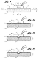
- the tactile actuator contacts the active portion of the device, and when energized, extends and presses upon the deformable elastomer, restricting or closing the feature in the active portion. This action may be illustrated by reference to Figures 1, 2a, 2b, and 2c .
- Figure 1 illustrates a microfluidic device 1 having a channel 3 in a substrate 10 of elastomeric material, on top of which is an elastomeric cover 4.
- a tactile device 6 having a tactile actuator 7 extendable downwardly by application of an actutating signal through wires 8, 9.
- Figure 2a the device of Figure 1 is illustrated in cross-section across 2-2, i . e ., in a plane containing the tactile actuator.
- the channel 3 in Figure 2a is shown unobstructed, i . e ., the tactile activator has not been energized.
- FIG 2b an enlarged view across 2-2 of Figure 1 , the tactile activator has been partially energized, with the result that it protrudes away from the tactile device 6, exerting pressure on top surface 5 of the device, and distorting the cover 4 and the walls 11 of the channel 3.
- the channel cross-section is decreased, and flow restricted accordingly.
- a portion of channel 3 has been closed off by the bulge 12 of the energized tactile activator.
- the elastomer material surrounding the feature, here the channel 3 may be, if desired, restricted to the elastomeric cover 4.
- the walls of the channel which are within the substrate 10 may be rigid, i . e ., of micromachined silica, silicon, glass, hard plastic, metal, etc.
- the flexible elastomeric portion is restricted in this embodiment to the cover.
- the actuator is further ("fully") energized, as a result of which the channel 3 is completely obscured.
- the tactile actuator serves as an on/off valve rather than an adjustable flow controller.
- the tactile actuator may be manufactured in an extended position, which retracts upon energizing, or may be applied to the microfluidics device in an energized state, closing or restricting the passage, further opening the passage upon de-energizing.
- a significant improvement in the performance, not only of the subject invention devices, but of other microfluidic devices which use pressure, i . e ., pneumatic pressure, to activate device features, may be achieved by molding the device to include one or more voids adjacent the channel walls. These voids allow for more complete closure or distortion of the respective feature.
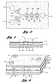
- An example of such construction is shown in Figure 3 .
- the device shown from above in plan with the elastomeric cover (4 in Figure 1 ) removed, a channel 20 is supplied fluid from supply reservoirs 21, 22 through "active" supply channels 23, 24. Fluid from the channel 20 exits into outlet reservoir 25. Five active portions are shown in the device at 26, 27, 28, 29, and 30.
- active portions 27 through 30 the respective channels (24, 20) are flanked by voids 27a and 27b, 28a and 28b, 29a and 29b, and 30a and 30b.
- Active portion 26 is flanked by but one void, 26a. The dotted circles in the active portions indicate where the tactile actuator will be energized to restrict or close the channel at these points.
- the channel 24 and active portion 27 are shown in a plane orthogonal to the channel length, in this case with cover 4 and tactile device 6 and tactile activator 7 in place.
- the actuator 7 bulges downwards, the walls 27c, 27d between channel 27 and its flanking voids 27a and 27b may distort, allowing for increased flexure at these active portions.
- Figure 3 also illustrates a peristaltic pump made possible by use of three active portions in series, i . e ., active portions 28, 29, and 30. By successively actutating end to end, pumping action may be obtained in either direction. By cycling the pumping action back and forth, or by energizing the active portions in an alternative pattern, a mixing action rather than a pumping action may be maintained.
- the preferred actuators at the present time are programmable Braille display devices such as those previously commercially available from Telesensory as the NavigatorTM Braille Display with GatewayTM software which directly translates screen text into Braille code. These devices generally consist of a linear array of "8-dot" cells, each cell and each cell “dot” of which is individually programmable. Such devices are used by the visually impaired to convert a row of text to Braille symbols, one row at a time, for example to "read” a textual message, book, etc. These devices are presently preferred because of their ready commercial availability.
- the microfluidic device active portions are designed such that they will be positionable below respective actutable "dots” or protrusions on the Braille display. Braille displays are available from Handy Tech, Blazie, and Alva, among other suppliers.
- U.S. Patent 5,580,251 discloses a Braille display device having a plurality of cavities having a positive and a negative electrode, the cavities filled with a polar organic gel maintained in the cavity by a flat elastomeric film. Upon application of a voltage differential between the electrodes, the gel in the cavity expands to raise a dimple in the elastomeric film.
- Such tactile actuating devices may be constructed of glass having metal plated cylindrical cavities, surmounted by a glass or rigid plastic top sheet which is provided with metal electrodes which will be located at the ends of the cylindrical cavities (but not touching the cylindrical metal plated electrodes).
- the cavity is filled with a polar organic gel such as a polyacrylamide gel.
- the elastomeric film which raises protrusions upon activation may be an elastomeric silicone film, and may form the elastomeric film 4 ( Figure 1 ) of the subject matter microfluidic devices.
- U.S. Patent 5,496,174 which employs a buildup of an electrorheological fluid. Such devices are more amenable to separate tactile actuating devices rather than integral actuating devices.
- U.S. Patent 5,718,588 discloses a simple electromechanical Braille-type device employing shape memory wires for displacement between "on” and “off” portions. Any known device or device yet to be developed may be used appropriately, especially those employing electrorheologic or magnetorheologic working fluids or gels.
- a pneumatically operated Braille device is disclosed in U.S. Patent 6,354,839 . Use of "voice coil” type structures, especially those employing strong permanent magnets are also contemplated.
- Other devices employing shape memory alloys and intrinsically conducting polymer sheets, are respectively disclosed in U.S. Patents 5,685,721 and 5,766,013 . The skilled electrical engineer can readily fabricate such devices.
- FIG. 5 An example of a wholly integrated device is illustrated by Figure 5 , consisting of nine layers and five subassemblies.
- the microfluidic device itself 40 is cast in a single layer of elastomer, in this case of a thickness corresponding to the desired channel height, for example 30 ⁇ m.
- Two inlet reservoirs 41 and 42 feed through inlet channels 43 and 44 to a central channel 45, which terminates at outlet reservoir 46.
- Four active portions are shown, one on each inlet channel, allowing flow control of each channel 43, 44, including switching between channels, and two further active portions along the central channel 45, which can be alternatively pulsed to mix the fluid stream in the channel, to crush cells in the channel, etc.
- Each of the active portions of device 40 an be identified by the optional flanking voids 48 in the active portions.
- the reservoirs, channels, and voids in this embodiment extend through the entire thickness of the device single layer 40. However, devices of multiple layers are also useful.
- subassembly 50 Positionable atop device 40 is subassembly 50, which consists of a rigid substance, for example a glass, ceramic, or rigid plastic substrate 51, and elastomeric layer 52.
- Subassembly 50 contains three through holes 53, 54, and 55, which can communicate with reservoirs 42, 41, and 46, respectively, when the layers are combined.
- Subassembly 50 also contains four cavities or wells, 56, 57, 58, and 59 which extend through substrate 51 but not elastomeric film 52.
- the inside surfaces 56a through 59a are metal plated to serve as an actuator electrode. These electrodes are commonly connected by metal foil or trace 59b, which serves as a common voltage supply to all cavities.
- the cavities, prior to final assembly, will be filled with organic polar fluid or gel as previously described.
- Subassembly 60 consists of rigid cover 61 and elastomeric insulative seal 62. Both the cover 61 and seal 62 are pierced by through holes 63, 64, and 65, which when assembled, allow communication through corresponding holes 53, 54, 55 in subassembly 50, and ultimately with reservoirs 42, 41, and 46 in the microfluidic device. The combination of these allows for the fluid reservoirs to be filled or emptied, e.g. by a syringe, etc.
- Electrodes 66, 67, 68, and 69 Extending downward from rigid cover 61 and through seal 62 are electrode buttons 66, 67, 68, and 69, and in electrical communication with these electrodes but between the seal 62 and the rigid cover 61, are conductive traces 66a, 67a, 68a, and 69a.
- Subassembly 70 is substantially a mirror image of subassembly 50, but does not contain through holes for communication with the reservoir.
- the various features are labeled as in subassembly 50.
- the conductive trace is offset from that of subassembly 50 so that the respective actuators can be independently controlled.
- Subassembly 80 is substantially a mirror image of subassembly 60, but again no through holes for reservoir communication are provided. A portion of the total number of dip pin connectors 71, 72 are shown in subassemblies 70, 80. Corresponding connectors are used to connect with the electrical traces of subassemblies 50, 60, but are omitted for clarity. Electrodes 86, 87, 88, and 89 allow for individual actuation of the extendable protrusions.
- Figure 6 illustrates the appearance of a completed device, with fluid connectors 91, 92, 93 attached to the cover 61 to facilitate fluid supply to the reservoir.
- the dip pin connectors on the back side of the device are not observable in this view.
- the entire device may be encapsulated with thermosetting resin, as is common for integrated circuits, leaving only fluid connectors 91, 92, 93 and electrical connectors 71, 72 extending out of the integrated device.
- the integrated device of Figures 5 and 6 may also be created in separate components.
- the actuator assemblies i.e. subassemblies 50, 60 and 70, 80 may be prepared as separate units.
- the microfluidic device 40 will be surmounted, top and bottom, with an additional elastomeric layer. Use of such non-integral structures allows the actuator portions to be repeatedly reused, replacing only the microfluidic device layers.
- Suitable Braille display devices suitable for non-integral use are available from Handy Tech Electronik GmbH, Horb, Germany, as the Graphic Window ProfessionalTM (GWP), having an array of 24 x 16 tactile pins.
- Pneumatic displays operated by microvalves have been disclosed by Orbital Research, Inc. said to reduce the cost of Braille tactile cells from 70 $ U.S. per cell to Ca. 5-10 $/cell.
- Piezoelectric actuators are also usable, for example in devices as shown in Figures 5 and 6 , where a piezoelectric element replaces the electrorheological fluid, and electrode positioning is altered accordingly.
- the microfluidic devices of the present invention have many uses.
- the nutrients supplied may need to be varied to simulate availability in living systems.
- supply channels with active portions to close or restrict the various channels, supply of nutrients and other fluids may be varied at will.
- An example is a three dimensional scaffolding system to create bony tissue, the scaffolding supplied by various nutrients from reservoirs, coupled with peristaltic pumping to simulate natural circulation.
- a further application involves cell crushing.
- Cells may be crushed by transporting them in channels through active portions and actuating channel closure to crush the cells flowing through the channels.
- Cell detection may be achieved, for example, by flow cytometry techniques using transparent microfluidic devices and suitable detectors. Embedding optical fibers at various angles to the channel can facilitate detection and activation of the appropriate activators. Similar detection techniques, coupled with the use of valves to vary the delivery from a channel to respective different collection sites or reservoirs can be used to sort embryos and microorganisms, including bacteria, fungi, algae, yeast, viruses, sperm cells, etc.
- a microfluidics device capable of embryo growth may be fabricated by multiexposure photolithography, using two masks. First, a large, somewhat rectangular (200 ⁇ m width x 200 ⁇ m depth) channel, optionally with a larger 200 ⁇ m deep by 300 ⁇ m length and 300 ⁇ m width growth chamber at one end is fabricated. Merging with the 200 ⁇ m x 200 ⁇ m channel is a smaller channel with a depth of ca. 30 ⁇ m, easily capable of closure by a Braille pin. Exiting the bulbous growth chamber are one or more thin (30 ⁇ m) channels.
- the merging channels and exit channels can be used to supply nutrients, etc., in any manner, i.e. continuous, pulsating, reverse flow, etc.
- the embryo may be studied by spectroscopic and/or microscopic methods, and may be removed by separating the elastomeric layer covering the PDMS body which houses the various channels.
- Construction of fluidic devices is preferably performed by soft lithography techniques, as described, for example by D. C. Duffy et al., Rapid Prototyping of Microfluidic Systems in Poly(dimethylsiloxane), ANALYTICAL CHEMISTRY 70, 4974-4984 (1998 ). See also, J.R. Anderson et al., ANALYTICAL CHEMISTRY 72, 3158-64 (2000 ); and M.A. Unger et al., SCIENCE 288, 113-16 (2000 ). Addition-curable RTV-2 silicone elastomers such as SYLGARD ® 184, Dow Coming Co., can be used for this purpose.
- Channels which are designed for complete closure must be of a depth such that the elastomeric layer between the microchannel and the actuator can approach the bottom of the channel.
- Manufacturing the substrate of elastomeric material facilitates complete closure, in general, as does also a cross-section which is rounded, particularly at the furthest corners (further from the actuator).
- the depth will also depend, for example, on the extension possible for the actuator's extendable protrusions.
- channel depths may vary quite a bit. A depth of less than 100 ⁇ m is preferred, more preferably less than 50 ⁇ m.
- Channel depths in the range of 10 ⁇ m to 40 ⁇ m are preferred for the majority of applications, but even very low channel depths, i.e. 1 nm are feasible, and depths of 500 ⁇ m are possible with suitable actuators, particularly if partial closure (“partial valving") is sufficient.
- the substrate may be of one layer or a plurality of layers.
- the individual layers may be prepared by numerous techniques, including laser ablation, plasma etching, wet chemical methods, injection molding, press molding, etc. However, as indicated previously, casting from curable silicone is most preferred, particularly when optical properties are important.
- Generation of the negative mold can be made by numerous methods, all of which are well known to those skilled in the art.
- the silicone is then poured onto the mold, degassed if necessary, and allowed to cure. Adherence of multiple layers to each other may be accomplished by conventional techniques.
- a preferred method of manufacture of some devices employs preparing a master through use of a negative photoresist.
- SU-8 50 photoresist from Micro Chem Corp., Newton, MA, is preferred.
- the photoresist may be applied to a glass substrate and exposed from the uncoated side through a suitable mask. Since the depth of cure is dependant on factors such as length of exposure and intensity of the light source, features ranging from very thin up to the depth of the photoresist may be created.
- the unexposed resist is removed, leaving a raised pattern on the glass substrate.
- the curable elastomer is cast onto this master and then removed.
- the material properties of SU-8 photoresist and the diffuse light from an inexpensive light source can be employed to generate microstructures and channels with cross-sectional profiles that are "rounded and smooth" at the edges yet flat at the top (i.e. bell-shaped). Short exposures tend to produce a radiused top, while longer exposures tend to produce a flat top with rounded corners. Longer exposures also tend to produce wider channels. These profiles are ideal for use as compressive, deformation-based valves that require complete collapse of the channel structure to stop fluid flow, as disclosed by M.A. Unger, et al., SCIENCE 2000, 288, 113 . With such channels, Braille-type actuators produced full closure of the microchannels, thus producing a very useful valved microchannel. Such shapes also lend themselves to produce uniform flow fields, and have good optical properties as well.
- a photoresist layer is exposed from the backside of the substrate through a mask, for example photoplotted film, by diffused light generated with an ultraviolet (UV) transilluminator.
- UV ultraviolet
- Bell-shaped cross-sections are generated due to the way in which the spherical wavefront created by diffused light penetrates into the negative photoresist.
- the exposure dose dependent change in the SU-8 absorption coefficient (3985 m -1 unexposed to 9700 m -1 exposed at 365 nm) limits exposure depth at the edges.
- the exact cross-sectional shapes and widths of the fabricated structures are determined by a combination of photomask feature size, exposure time/intensity, resist thickness, and distance between the photomask and photoresist.
- backside exposure makes features which are wider than the size defined by the photomask and in some cases smaller in height compared to the thickness of the original photoresist coating, the change in dimensions of the transferred patterns is readily predicted from mask dimensions and exposure time.
- the relationship between the width of the photomask patterns and the photoresist patterns obtained is essentially linear (slope of 1) beyond a certain photomask aperture size. This linear relationship allows straightforward compensation of the aperture size on the photomask through simple subtraction of a constant value.
- bell-shaped cross-section microchannels of 30 ⁇ m thickness was evaluated by exerting an external force onto the channel using a piezoelectric vertical actuator of commercially available refreshable Braille displays. Spaces may be left between the membrane and the wall when the channel cross-section has discontinuous tangents, such as in rectangular cross-sections. In contrast, a channel with a bell-shaped cross-section is fully closed under the same conditions.
- PDMS poly(dimethylsiloxane)
- the technique described is cost- and time-effective compared to other photolithographic methods for generating well defined rounded profiles such as gray-scale mask lithography, or laser beam polymerization because there is no need for special equipment such as lasers, collimated light sources (mask aligner), or submicron resolution photomasks; it only requires a transilluminator available in many biological labs.
- the backside exposure technique can generate more profiles compared to other soft lithography-based patterning methods such as microfluidic mask lithography and the use of patterned laminar flows of etchant in an existing microchannel.
- bell-shaped microchannels When used as deformation-based microfluidic valves, these bell-shaped microchannels showed improved self-sealing upon compression compared to conventional rectangular or semi-circular cross-section channels as demonstrated by simulations, and by experiments.
- a bell-shaped channel (width: 30 ⁇ m; height 30 ⁇ m) was completely closed by an 18 gf-force squeeze of a Braille pin. It is notable that channels that have the bell-shaped cross-sections with "gently sloping" sidewalls cannot be fabricated by melting resist technology, one of the most convenient methods to fabricate photomask-definable rounded patterns, because the profile is determined by surface tension.
- the bell-shaped channels maximize the cross-sectional area within microfluidic channels without compromising the ability to completely close channels upon deformation.
- the channel cross-section described here is larger than previously reported, pneumatically actuated deformation-based valves (100 ⁇ m in width; 20 ⁇ m in height) and may be more suitable for mammalian cell culture.
- the bell-shaped cross-sections provide channels with flat ceilings and floors, which is advantageous for reducing aberrations in optical microscopy and in obtaining flow fields with a more uniform velocity profile across the widths of the channel.
- the extension outwards of the tactile actuators must be sufficient for their desired purpose. Complete closure of a 40 ⁇ m deep microchannel, for example, will generally require a 40 ⁇ m extension ("protrusion") or more when a single actuator is used, and about 20 ⁇ m or more when dual actuators on opposite sides of the channel are used. For peristaltic pumping, mixing, and flow regulation, lesser extensions relative to channel height are useful.
- the areal size of the tactile activators may vary appropriately with channel width and function (closure, flow regulation, pumping, etc.), and may preferably range from 40 ⁇ m to about 2 mm, more preferably 0.5 mm to 1.5 mm. Larger and smaller sizes are possible as well.
- the actuators must generate sufficient force.
- the force generated by one Braille-type display pin is approximately 176 mN, and in other displays may be higher or lower.
- the invention pertains to a microfluidic device having at least one active portion consisting of a fluid channel or repository, having an elastomeric cover and optionally but preferably, elastomeric walls, the volume and/or cross-sectional area of which may be selectively varied by imposition of pressure from a tactile actuator external to the microfluidic device.
- an array of tactile actuators may be used to supply the actuating pressure, the individual tactile protrusions being capable of being individually addressed or addressed in groups, for example by simple computer programming, or input of an ASCII character string.
- a series of tactile actuators external to a microfluidic channel are actuated in a pattern to provide a peristaltic pumping action or a mixing action with respect to fluid contained in the channel.
- tactile actuators are employed to selectively close or open supply or outlet channels of a microfluidic device, optionally in response to signals generated by passage of fluid or particles in one or more channels of the microfluidic device.
- the tactile actuators are maintained external to the microfluidic device per se but are assembled into an integrated structure containing fluid inlets and outlets and electrical connections for energizing respective tactile actuators.
- the subject invention devices are employed as microreactors, tissue culture devices, cell culture devices, cell sorting devices, or cell crushing devices.
- a standard Braille display with commercially available software is a particularly elegant means of actuating device features such as valve closing, pumping, and mixing.
- the elastomeric microfluidic device is designed such that the appropriate features are positioned below respective Braille protrusions in an 8-dot Braille cell, or below protrusions located in various cells in the display.
- a text editor with scrolling capability can scan a single or a plurality of lines of ASCII characters, and transfer appropriate signals to the display.
- Variable speed scrolling can be used to alter the speed of actuation.
- ASCII "a” is represented by the digital code 10000000 while a "coma” is represented by 00000100.
- Each of these codes will actuate a single protrusion in an 8-dot cell.
- Braille software is available for use in computers operating in numerous environments. For Windows ® operating systems, for example, JAWS 4.0 is available. However, the concept is simple and easily implemented in numerous programming languages such as Fortran, Basic, and Visual Basic.
- each individual reservoir may be connected with a growth channel or chamber at will.
- peristaltic pumping may be performed at a variety of flow rates. Uneven, pulsed flow typical of vertebrate circulatory systems can easily be created.
- microfluidics device per se, coupled with a simple, programmable external actuator, enables a cost-effective system to be prepared, where the microfluidic device is relatively inexpensive and disposable, despite its technological capabilities.
- Combinatorial, regulated flow with multiple pumps and valves that offer more flexibility in microfluidic cell studies in a laptop to handheld-sized system are created by using a grid of tiny actuators on refreshable Braille displays. These displays are typically used by the visually impaired as tactile analogs to computer monitors. Displays usually contain 20-80 rows of cells, each holding 8 (4x2) vertically moving pins ( ⁇ 1-1.3 mm). Two pins on the same cell may typically be 2.45 mm apart center to center and 3.8 mm apart on different cells. Each pin may have the potential to protrude 0.7 ⁇ 1 mm upward using piezoelectric mechanisms, and may hold up to ⁇ 15-20cN. Control of Braille pins actuators is accomplished by changing a line of text in a computer program.
- Braille displays are pre-packaged with software, easy to use, and readily accessible. They are designed for individual use, and range from walkman to laptop sizes while using AC or battery power. By using the moving Braille pins against channels in elastomeric, transparent rubber, it is possible to deform channels and create in situ pumps and valves.
- a microfluidic device is fabricated of PDMS (SYLGARD ® 184) with active portions located below a commercial Braille display having 8-dot cells, the protrusions of which are approximately 1 mm in diameter, at spacings of 2.5 mm center-to-center in each cell, with an intercell distance of 3.2 mm. Each protrusion can protrude 1.5 mm from the surface of the display when activated.
- the elastomeric PDMS device channels have a relatively thin 100-200 ⁇ m bottom PDMS membrane, which rests upon the Braille display.
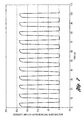
- the microfluidic device has a common observation channel and two valved supply channels, and is used to study Braille display actuated valving.
- the valves are constructed as described earlier with voids adjacent the active portions, and located on the microfluidic device so as to be below dimples on a commercial Braille display.
- One inlet channel is supplied with a solution of fluorescent dye from an inlet reservoir, while the other inlet reservoir contains no dye.
- the respective valves are opened and closed repeatedly by scrolling through text containing alternate "a" and ",”.
- the fluorescence in the common channel is monitored. Fluid flow is induced by a syringe communicating with the common channel outlet.
- the device is thus similar to that of Figure 3 .
- Figure 7 illustrates the observed fluorescence in the channel as the respective inlet valves were alternately closed, after subtracting background noise. As can be seen, the valving is highly effective. The plot is similar to that presented in M.A. Unger et al., SCIENCE 288, 113 (2000 ).
- Photoplotted films were ordered from CAD/Art Services, Inc. (Poway, CA).
- Photoresist was exposed by a transilluminator (FB-TIV-816A, Fisher Scientific) with six replaced fluorescent blacklight lamps (TL-D15W/08, Philips), and a PLA-501FA mask aligner by Canon U.S.A., Inc. (Lake Success, NY). Oxidation was performed using a plasma etcher (Plasma Prep II; Structure Probe Inc., West Chester, PA). A Braille display DotView DV-1 was obtained from KGS Corp. (Saitama, Japan). Phosphate-buffered saline (PBS) was obtained from Fisher Scientific.
- Photomasks of microchannels were produced by photoplotting at 20,000 dpi to form an exposure mask.
- a 30 ⁇ m layer of SU-8 50 was coated on a glass substrate by spin coating at 4,500 rpm, softbaking at 95 C, and exposing from the backside using a transilluminator at the maximum intensity (8 mW/cm 2 ).
- a photomask film is placed on the non-coated side of the substrate and sandwiched by two 5-inch composite quartz glass photomask blanks (thickness, 2.38 mm). The coated side of the substrate is covered with a yellow-tinted vinyl film to prevent ultraviolet light from reentering into the SU-8 coating.
- the pattern of the mold was transferred into a 5 mm thick poly(dimethylsiloxane) (PDMS) slab by casting of silicone prepolymer.
- PDMS poly(dimethylsiloxane)
- a 200 ⁇ m thick PDMS membrane was also fabricated by spin coating of prepolymer onto a silanized glass wafer. Both the slab and the membrane were cured on a leveled surface at room temperature for 1 day followed by curing at 60 C for 1 h. The slab was finally cured at 150 C for 15 min. Both the slab and membrane were bonded after oxidation by the methods disclosed by Duffy, ANALYTICAL CHEMISTRY 70 , op. cit.
- the fabricated PDMS microfluidic device was mechanically fixed to the surface of the Braille display. To observe leakage of the channel, the centerline of the channel was aligned with the center of the Braille pin under a fluorescent stereomicroscope. The Braille pin was then controlled to push the channel upward. The maximum force is 176.4 mN.
- Channel closure (valving) was analyzed using visualization of fluorescence of the Braille pin through a channel filled with a dye solution. Measurement of electrical resistance of liquid in the channel may also be used, by fixing the tips of two platinum wires (254 ⁇ m in diameter) at the ends of a channel containing a conductive solution. As the restriction of the passage increases, the measured resistance increases as well.
- the inside of the microchannel was filled with green food color.
- Each silicone chip is a multilayer assembly of poly(dimethylsiloxane) (PDMS).
- the bottom layer is formed at a thickness of 120 ⁇ m by spin coating a 1:10 (curing agent:base) ratio of prepolymer (Sylgard 184, Dow-Corning) onto a silanized glass wafer at 200 rpm for 4 minutes.
- a Si master with positive relief structure is made of photoresist (SU-8, MicroChem) defined through backside diffused-light photolithography as described in Example 2.
- Prepolymer (1:10 ratio) is cast against the positive relief features to form a ⁇ 1 mm middle layer. The resultant negative replica formed channels when sealed by the bottom layer.
- the microfluidics device includes a reservoir layer on top of the microfluidic assembly to avoid additional tubing.
- the reservoir and channels remain a closed system (with the exception of gases) for protection against spills and contamination in non-sterile environments.
- Reagent can be added or subtracted from this closed system using 30 gauge needles since PDMS acts as a sealant.
- Prepared devices are aligned onto Braille pins, clamped down, placed near a dish of distilled water, and covered loosely with saran wrap. The entire setup is placed into a dry incubator with a nearby laptop that controls the fluidic movement inside each device.
- the channel architecture consists of multiple loops that are interlinked during seeding, and valved shut from each other during fluidic circulation.
- Each loop is connected to the main reservoir and contains a segment linked to other loops. Since each loop had its inlet and outlet connected to the same reservoir, hydrostatic pressure between the two ends were the same. While one seeding procedure can prepare every recycle loop, each loop can be separated by valves and run independently of one another.
- one needle is inserted into one end of the seeding circuit as a vent, and another on the other end carrying cells. Valves define only one path for injected cells to navigate, and allow stagnant flow for cells to attach. This makes precision seeding more convenient and efficient than previous methods.
- This design is used to create a cellular flow assay. Seeded cells are first perfused with media rich in growth factors (15 % Fetal Bovine Serum), and then with limiting media (2% Horse Serum). When in limiting media, moderate flow rates cause cell growth while slow flow rates shunt growth and cause cell death. In general, proliferation occurs at the upstream end and not the downstream end, suggesting that concentration gradients are present from one end of the loop to the other. Although this may be an artifact of the pump, this trend is consistent at all flow rates, including the slowest pumps which actuate once every 25 seconds.
- This flow assay features the ability to selectively position cells, and to regulate their fluidic environment for extended periods of times. These features make possible the study of cells in simulated in vivo environments. Just as a circulatory system overcomes slow mass transport in multicellular organisms, regulated microcirculation will likewise benefit cells residing in microfluidic channels by actively delivering fresh nutrients, removing cellular waste, or providing for concentration. One can arbitrarily treat cells to differentiate, grow, or undergo apoptosis. Cell to cell chemical signaling can be studied by reconfiguring the fluidic direction. Such cellular assays can be used for toxicology, pharmacology, or as a biosensor.
- the invention is further demonstrated by switching between laminar streams and mixing by programming, and by seeding, compartmentalizing, and sustaining C2C 12 mouse myoblasts within microfluidic chips over extended time periods (up to 3 weeks), and assaying myoblast proliferation under different flow patterns.
- Braille displays (Navigator, Telesensory, CA, USA) provided a grid of microactuator pins. These pins reflected text displayed on a computer. The most accessible method of control uses a text editor (Boxer) to auto-scroll through a prearranged text designed to actuate the correct Braille pins. More flexible programs, coded in Visual Basic (Microsoft), continually update a line of character corresponding to desired pin actuation. Braille screen readers (HAL, JAWS) directly controlled pin actuation based on the refreshing line of characters. Eight pins (4x2) represented all possible characters. Characters correspond to 213 unique combinations out of 256 possible ones, or 83 % of the possible combinations. All combinations for the top three rows of pins representing each character have a corresponding letter and are under full control.
- Mouse C2C12 mesenchymal precursor cells are cultured and harvested by conventional methods.
- Cells are cultured under 5% CO 2 on Petri dishes (Fisher) in Dulbecco's Modified Eagle Medium (DMEM) (Invitrogen) media containing 15 % Fetal Bovine Serum, 100 ug/ml streptomycin, 100 ug/ml penicillin.
- DMEM Dulbecco's Modified Eagle Medium
- PBS Invitrogen
- These cells are injected into capillary channels and maintained under the same media.
- the microchannels are pretreated with media incubation overnight.
- Cells are cultured in the devices on Braille displays in 5% CO 2 at 37°C.
Landscapes
- Engineering & Computer Science (AREA)
- Chemical & Material Sciences (AREA)
- General Engineering & Computer Science (AREA)
- Health & Medical Sciences (AREA)
- Dispersion Chemistry (AREA)
- Theoretical Computer Science (AREA)
- Physics & Mathematics (AREA)
- General Health & Medical Sciences (AREA)
- General Physics & Mathematics (AREA)
- Clinical Laboratory Science (AREA)
- Mechanical Engineering (AREA)
- Organic Chemistry (AREA)
- Zoology (AREA)
- Chemical Kinetics & Catalysis (AREA)
- Hematology (AREA)
- Analytical Chemistry (AREA)
- Wood Science & Technology (AREA)
- Bioinformatics & Cheminformatics (AREA)
- Life Sciences & Earth Sciences (AREA)
- Genetics & Genomics (AREA)
- Pure & Applied Mathematics (AREA)
- Mathematical Analysis (AREA)
- Biotechnology (AREA)
- Microbiology (AREA)
- Sustainable Development (AREA)
- Mathematical Physics (AREA)
- Educational Technology (AREA)
- Biochemistry (AREA)
- Mathematical Optimization (AREA)
- Biomedical Technology (AREA)
- Algebra (AREA)
- Computational Mathematics (AREA)
- Business, Economics & Management (AREA)
- Educational Administration (AREA)
- Human Computer Interaction (AREA)
- Apparatus Associated With Microorganisms And Enzymes (AREA)
- Micromachines (AREA)
- Automatic Analysis And Handling Materials Therefor (AREA)
- Reciprocating Pumps (AREA)
- Surface Acoustic Wave Elements And Circuit Networks Thereof (AREA)
Claims (18)
- Mikrofluidvorrichtung mit einem Substrat, das zumindest einen leeren Raum (3) aufweist, dessen Form und/oder Volumen verändert werden soll, wobei der leere Raum auf einer Seite durch eine verformbare, elastomere Schicht (4) definiert ist; und einem elektronisch ansteuerbaren, taktilen Betätigungselement (6, 7), das sich in der Nähe einer Seite der elastomeren Schicht, entfernt vom leeren Raum, befindet und eine Mehrzahl von beabstandeten, einzeln ansteuerbaren, ausfahrbaren Vorsprüngen aufweist, von denen zumindest einer, wenn er betätigt wird, an der verformbaren, elastomeren Schicht ansetzt, wobei er diese verformt und die Form und/oder das Volumen des leeren Raums verändert.
- Vorrichtung nach Anspruch 1, wobei der leere Raum einen Strömungskanal, ein Reservoir und eine Zellen vernichtende Kammer aufweist.
- Vorrichtung nach Anspruch 1, wobei das taktile Betätigungselement eine regelmäßige geometrische Anordnung von ausfahrbaren Vorsprüngen aufweist.
- Vorrichtung nach Anspruch 1, wobei das taktile Betätigungselement eine programmierbare Braille-Anzeige aufweist.
- Vorrichtung nach Anspruch 1, mit zumindest einem Fluid pumpenden Abschnitt, der einen Strömungskanal und ein taktiles Betätigungselement mit einer Mehrzahl von ausfahrbaren Vorsprüngen aufweist, die in Reihe entlang des Strömungskanals angeordnet sind, und wobei das Betätigungselement programmiert ist, um die Vorsprünge in einer Sequenz auszufahren und einzuziehen, was bewirkt, dass Flüssigkeit durch diesen Strömungskanal gepumpt wird.
- Vorrichtung nach Anspruch 1, mit zumindest einem mit Ventilen versehenen Strömungskanal, der sich in der Nähe eines ausfahrbaren Vorsprungs eines taktilen Betätigungselements befindet, wobei der Kanal eine Tiefe aufweist, so dass der vollständig ausgefahrene Zustand des ausfahrbaren Vorsprungs die elastomere Schicht zu der Tiefe des Strömungskanals verformt, wodurch der Strömungskanal verschlossen wird.
- Vorrichtung nach Anspruch 1, mit zumindest einem mit Ventilen versehenen Mikrokanal, der eine Tiefe von 1 µm bis 100 µm hat, wobei der Mikrokanal auf einer Seite durch eine elastomere Schicht mit einer Dicke von 1 µm bis 1 mm definiert ist.
- Vorrichtung nach Anspruch 1, wobei das Substrat ein elastomeres Material ist.
- Vorrichtung nach Anspruch 1, wobei sowohl das Substrat als auch die elastomere Schicht ein Silikonelastomer aufweisen.
- Vorrichtung, die zum Züchten eines lebenden Organismus in einem Fluid geeignet ist, wobei die Fluidzusammensetzung als Fluidströmung zuführt wird, wobei die Vorrichtung eine Mikrofluidvorrichtung nach Anspruch 1 umfasst, wobei zumindest ein leerer Raum eine Wachstumskammer für den Organismus aufweist, die mit zumindest einem Reservoir in Fluidverbindung steht, und einen Fluid pumpenden Abschnitt hat, der einen Strömungskanal und ein taktiles Betätigungselement aufweist, das eine Mehrzahl von ausfahrbaren Vorsprüngen umfasst, die in Reihe entlang des Strömungskanals angeordnet sind, und das programmiert ist, um die Vorsprünge in einer Sequenz auszufahren und einzuziehen, was bewirkt, dass Flüssigkeit durch diesen Strömungskanal gepumpt wird, wobei der Strömungskanal mit dem Reservoir und der Wachstumskammer kommuniziert, so dass Fluid aus dem Reservoir durch die Wachstumskammer fließt.
- Vorrichtung nach Anspruch 10, weiters mit einer Mehrzahl von Reservoirs, wobei ein mit Ventilen versehener Strömungskanal, der mit der Wachstumskammer in Fluidverbindung steht, jedem Reservoir zugeordnet ist, so dass die Fluidströmung in die Wachstumskammer von einem oder einer Mehrzahl von Reservoirs ausgewählt werden kann.
- Verfahren zum Züchten eines Organismus, umfassend das Einbringen des Organismus oder eines Vorläufers davon in einen leeren Raum in einer Vorrichtung nach Anspruch 1, und das Pumpen eines Wachstumsmediumfluids am Organismus vorbei mittels einer peristaltischen Mikrokanal-Pumpe, die vom taktilen Betätigungselement betrieben wird.
- Verfahren nach Anspruch 12, wobei die Vorrichtung eine Mehrzahl von Fluidreservoirs und eine Mehrzahl von zugehörigen, mit Ventilen versehenen Mikrokanälen enthält, so dass das Fluid, das am Organismus vorbei gepumpt wird, durch Öffnen und/oder Schließen ausgewählter Ventile mittels des taktilen Bedienungselements aus einem oder mehreren gewählten Reservoirs abgeleitet werden kann.
- Verfahren nach Anspruch 13, wobei jeder mit Ventilen versehene Mikrokanal weiters eine peristaltische Pumpe aufweist.
- Verfahren nach Anspruch 13, wobei die Durchflussrate des Fluids am Organismus vorbei durch Variieren der Betätungsrate der sequentiell positionierten, ausfahrbaren Vorsprünge entlang eines Mikrokanals, der mit dem leeren, den Organismus enthaltenden Raum in Fluidverbindung steht, variiert wird.
- Verfahren nach Anspruch 15, wobei der Fluiddurchfluss durch Schließen oder Öffnen von jeweiligen Mikrokanalventilen, die mit einer Mehrzahl von Fluidzuführ-Mikrokanälen verbunden sind, verändert wird.
- Verfahren zum Umsetzen einer Fluidsteuerung in einer Mikrofluidvorrichtung, umfassend das Auswählen einer Mikrofluidvorrichtung nach Anspruch 1, das Auswählen einer geometrischen Anordnung ausfahrbarer Vorsprünge als taktiles Betätigungselement, und das Betätigen von einzelnen ausfahrbaren Vorsprüngen in der geometrischen Anordnung mittels eines Computerprogramms.
- Verfahren nach Anspruch 14, wobei die geometrische Anordnung eine Braille-Anzeige ist, und wobei die einzelnen Vorsprünge betätigt werden, indem der Anzeige ein ASCII-Zeichen zugeführt wird.
Applications Claiming Priority (3)
| Application Number | Priority Date | Filing Date | Title |
|---|---|---|---|
| US45329803P | 2003-03-10 | 2003-03-10 | |
| US453298P | 2003-03-10 | ||
| PCT/US2004/007246 WO2004081741A2 (en) | 2003-03-10 | 2004-03-10 | Integrated microfluidic control employing programmable tactile actuators |
Publications (2)
| Publication Number | Publication Date |
|---|---|
| EP1601874A2 EP1601874A2 (de) | 2005-12-07 |
| EP1601874B1 true EP1601874B1 (de) | 2009-05-27 |
Family
ID=32990749
Family Applications (1)
| Application Number | Title | Priority Date | Filing Date |
|---|---|---|---|
| EP04719255A Expired - Lifetime EP1601874B1 (de) | 2003-03-10 | 2004-03-10 | Intergrierte mikrofluidische kontrollvorrichtung mit programmierbaren taktilen stellgliedern |
Country Status (9)
| Country | Link |
|---|---|
| US (2) | US7745211B2 (de) |
| EP (1) | EP1601874B1 (de) |
| JP (1) | JP2006527093A (de) |
| KR (1) | KR20050112095A (de) |
| AT (1) | ATE432420T1 (de) |
| BR (1) | BRPI0408676A (de) |
| DE (1) | DE602004021239D1 (de) |
| ES (1) | ES2327231T3 (de) |
| WO (1) | WO2004081741A2 (de) |
Cited By (2)
| Publication number | Priority date | Publication date | Assignee | Title |
|---|---|---|---|---|
| US9810607B2 (en) | 2011-09-14 | 2017-11-07 | Embl | Microfluidic device |
| US11913894B2 (en) | 2020-12-08 | 2024-02-27 | Kyndryl, Inc. | Dynamic surface profile change in device for better gripping |
Families Citing this family (78)
| Publication number | Priority date | Publication date | Assignee | Title |
|---|---|---|---|---|
| JP2004309145A (ja) * | 2003-04-02 | 2004-11-04 | Hitachi High-Technologies Corp | 化学分析装置及び化学分析用構造体 |
| US7597815B2 (en) * | 2003-05-29 | 2009-10-06 | Dressel Pte. Ltd. | Process for producing a porous track membrane |
| WO2005123950A2 (en) * | 2004-05-19 | 2005-12-29 | Massachusetts Institute Of Technology | Perfused three-dimensional cell/tissue disease models |
| US9477233B2 (en) * | 2004-07-02 | 2016-10-25 | The University Of Chicago | Microfluidic system with a plurality of sequential T-junctions for performing reactions in microdroplets |
| US20070243627A1 (en) * | 2004-09-30 | 2007-10-18 | Shuichi Takayama | Computerized control method and system for microfluidics and computer program product for use therein |
| WO2006138743A2 (en) * | 2005-06-23 | 2006-12-28 | Bioprocessors Corp. | Fluid transfer device |
| US20070090166A1 (en) | 2005-10-18 | 2007-04-26 | Shuichi Takayama | Microfluidic cell culture device |
| US20070084706A1 (en) * | 2005-10-18 | 2007-04-19 | Shuichi Takayama | Microfluidic cell culture device and method for using same |
| US20070231901A1 (en) * | 2005-12-02 | 2007-10-04 | Shuichi Takayama | Microfluidic cell culture media |
| CN101415813B (zh) | 2006-02-03 | 2013-04-10 | 微芯片生物工艺学股份有限公司 | 微流体装置 |
| AT503116B1 (de) * | 2006-03-17 | 2007-08-15 | Dbs Daily Business Support Sof | Mikroreaktor |
| US8123192B2 (en) * | 2006-10-18 | 2012-02-28 | California Institute Of Technology | Control arrangement for microfluidic devices and related methods and systems |
| US7790118B2 (en) * | 2006-10-18 | 2010-09-07 | California Institute Of Technology | Microfluidic devices and related methods and systems |
| JP4939910B2 (ja) | 2006-11-29 | 2012-05-30 | 株式会社東芝 | マイクロ化学分析システム及びマイクロ化学分析装置 |
| KR100851279B1 (ko) | 2006-12-07 | 2008-08-08 | 한국전자통신연구원 | 전기 유변 유체를 이용한 점자 디스플레이 장치 및 그 제조방법 |
| WO2008071351A1 (de) * | 2006-12-14 | 2008-06-19 | Boehringer Ingelheim Microparts Gmbh | Vorrichtung zur aufnahme oder manipulation einer flüssigkeit |
| WO2008134363A1 (en) * | 2007-04-25 | 2008-11-06 | The Regents Of The University Of Michigan | Tunable elastomeric nanochannels for nanofluidic manipulation |
| JP2010536348A (ja) * | 2007-08-24 | 2010-12-02 | スマート・バイオシステムズ・エーピーエス | 灌流のための中規模バイオリアクタープラットフォーム |
| WO2009039433A1 (en) * | 2007-09-20 | 2009-03-26 | Incept Biosystems Inc. | Analytical microfluidic culture system |
| US20100041128A1 (en) * | 2008-01-08 | 2010-02-18 | Medtrain Technologies, Llc | Microfluidic Device for Application of Shear Stress and Tensile Strain |
| US20110236970A1 (en) * | 2008-08-01 | 2011-09-29 | Smart Biosystems Aps | Chamber of a bioreactor platform |
| WO2010042284A2 (en) * | 2008-10-10 | 2010-04-15 | The Regents Of The University Of Michigan | Microfluidic control systems |
| US8692815B2 (en) * | 2009-11-06 | 2014-04-08 | Bose Corporation | Touch-based user interface user selection accuracy enhancement |
| US20110109560A1 (en) | 2009-11-06 | 2011-05-12 | Santiago Carvajal | Audio/Visual Device Touch-Based User Interface |
| US8669949B2 (en) * | 2009-11-06 | 2014-03-11 | Bose Corporation | Touch-based user interface touch sensor power |
| US9201584B2 (en) | 2009-11-06 | 2015-12-01 | Bose Corporation | Audio/visual device user interface with tactile feedback |
| US8350820B2 (en) * | 2009-11-06 | 2013-01-08 | Bose Corporation | Touch-based user interface user operation accuracy enhancement |
| US8638306B2 (en) * | 2009-11-06 | 2014-01-28 | Bose Corporation | Touch-based user interface corner conductive pad |
| US20110113371A1 (en) * | 2009-11-06 | 2011-05-12 | Robert Preston Parker | Touch-Based User Interface User Error Handling |
| US8686957B2 (en) * | 2009-11-06 | 2014-04-01 | Bose Corporation | Touch-based user interface conductive rings |
| EP2510351A4 (de) * | 2009-12-07 | 2018-01-10 | Yale University | Labelfreie zellmanipulation und -sortierung mithilfe biokompatibler ferrofluide |
| DE102011015184B4 (de) * | 2010-06-02 | 2013-11-21 | Thinxxs Microtechnology Ag | Vorrichtung für den Transport kleiner Volumina eines Fluids, insbesondere Mikropumpe oder Mikroventil |
| WO2012002967A1 (en) * | 2010-07-01 | 2012-01-05 | Empire Technology Development Llc | Method and system for cell and tissue cultivation |
| EP2606154B1 (de) | 2010-08-20 | 2019-09-25 | Integenx Inc. | Integriertes analysesystem |
| EP2625425A2 (de) | 2010-10-07 | 2013-08-14 | Vanderbilt University | Peristaltische mikropumpe sowie zugehörige systeme und verfahren |
| US9012255B1 (en) * | 2010-10-27 | 2015-04-21 | Dunan Microstaq, Inc. | MEMS package |
| JP2013545109A (ja) | 2010-12-09 | 2013-12-19 | ケヴァル,アルテュール | 流体サンプル分析用のマイクロ流体デバイス |
| US10865440B2 (en) | 2011-10-21 | 2020-12-15 | IntegenX, Inc. | Sample preparation, processing and analysis systems |
| US20150136604A1 (en) | 2011-10-21 | 2015-05-21 | Integenx Inc. | Sample preparation, processing and analysis systems |
| HUP1100601A2 (hu) * | 2011-10-28 | 2013-06-28 | Tacmonco Ltd | Tapintással érzékelhetõ jelzõeszköz, különösen látássérült személyek képi és grafikus információval történõ ellátására |
| JP2012068267A (ja) * | 2012-01-10 | 2012-04-05 | Toshiba Corp | マイクロ化学分析システム及びマイクロ化学分析装置 |
| WO2013148312A1 (en) * | 2012-03-26 | 2013-10-03 | Alere San Diego, Inc. | Microfluidic pump |
| US9579446B2 (en) * | 2012-10-05 | 2017-02-28 | David Hirshberg | MEMS based filter and catalizer |
| US20160296945A1 (en) | 2013-03-15 | 2016-10-13 | Ancera, Inc. | Systems and methods for active particle separation |
| WO2014145765A1 (en) | 2013-03-15 | 2014-09-18 | Ancera, Inc. | Systems and methods for bead-based assays in ferrofluids |
| DK3041926T3 (da) * | 2013-09-05 | 2020-06-08 | Univ Bern | Indretning til in-vitro-modellering af in-vivo-væv af organer |
| US9604214B2 (en) * | 2013-10-01 | 2017-03-28 | Owl biomedical, Inc. | Cell sorting system using microfabricated components |
| CN105813721B (zh) * | 2013-10-16 | 2019-11-05 | 不列颠哥伦比亚大学 | 用于以小体积配制颗粒的装置 |
| EP3071333A4 (de) | 2013-11-18 | 2017-11-15 | IntegenX Inc. | Kassetten und instrumente zur probenanalyse |
| KR102137510B1 (ko) * | 2013-12-17 | 2020-07-27 | 삼성디스플레이 주식회사 | 정전척 |
| US9969964B2 (en) * | 2013-12-23 | 2018-05-15 | Purdue Research Foundation | Disease-on-a-chip |
| WO2015116068A1 (en) * | 2014-01-29 | 2015-08-06 | Hewlett-Packard Development Company, L.P. | Microfluidic valve |
| WO2015179098A1 (en) | 2014-05-21 | 2015-11-26 | Integenx Inc. | Fluidic cartridge with valve mechanism |
| KR101635459B1 (ko) * | 2014-07-22 | 2016-07-11 | 광운대학교 산학협력단 | 프로그래밍 가능한 마이크로 펌프 |
| CN110042060A (zh) * | 2014-08-05 | 2019-07-23 | 雅马哈发动机株式会社 | 板 |
| ES2860938T3 (es) | 2014-09-25 | 2021-10-05 | European Molecular Biology Laboratory | Dispositivo microfluídico para la generación de muestras combinatorias |
| WO2016065073A1 (en) | 2014-10-22 | 2016-04-28 | Integenx Inc. | Systems and methods for sample preparation, processing and analysis |
| US20170369830A1 (en) * | 2014-12-11 | 2017-12-28 | Icomes Lab Co., Ltd. | Cell culture method and cell culture device |
| US10466194B2 (en) | 2015-02-13 | 2019-11-05 | Drexel University | Piezoelectric biochips having fluidic channels |
| WO2016205375A1 (en) * | 2015-06-18 | 2016-12-22 | The Regents Of The University Of Michigan | Microfluidic actuators with integrated addressing |
| US10233491B2 (en) | 2015-06-19 | 2019-03-19 | IntegenX, Inc. | Valved cartridge and system |
| US11285490B2 (en) | 2015-06-26 | 2022-03-29 | Ancera, Llc | Background defocusing and clearing in ferrofluid-based capture assays |
| US10898896B2 (en) | 2015-09-25 | 2021-01-26 | Arizona Board Of Regents On Behalf Of The University Of Arizona | Thermally-actuated valve for metering of biological samples |
| WO2017061619A1 (ja) * | 2015-10-09 | 2017-04-13 | シスメックス株式会社 | 検体処理チップ、検体処理装置および検体処理方法 |
| WO2017069256A1 (ja) * | 2015-10-23 | 2017-04-27 | 国立研究開発法人科学技術振興機構 | ナノ流体デバイス及び化学分析装置 |
| ES2614252B1 (es) * | 2015-10-27 | 2018-03-12 | Universidad De Zaragoza | Chip microfluídico, dispositivo microfluídico, procedimientos y usos asociados |
| FR3043093A1 (fr) * | 2015-10-30 | 2017-05-05 | Commissariat Energie Atomique | Dispositif de traitement d'au moins une cellule biologique, notamment en vue d'une delivrance intracellulaire |
| WO2018160574A1 (en) | 2017-02-28 | 2018-09-07 | Alere San Diego Inc. | Microfluidic devices and related methods |
| WO2018183744A1 (en) | 2017-03-29 | 2018-10-04 | The Research Foundation For The State University Of New York | Microfluidic device and methods |
| US11269416B2 (en) * | 2017-11-15 | 2022-03-08 | Google Llc | Touch communication device |
| IL263127B (en) * | 2018-11-19 | 2022-07-01 | The Interdisciplinary Center Herzliya Cc | A liquid-based biological system |
| US11447734B2 (en) * | 2019-06-28 | 2022-09-20 | Vanderbilt University | Continuous automated perfusion culture analysis system (CAPCAS) and applications of same |
| US11645948B2 (en) * | 2020-03-10 | 2023-05-09 | Tactile Solutions, Inc. | Capture plate assembly for braille display |
| EP4182429A1 (de) * | 2020-07-17 | 2023-05-24 | Vanderbilt University | Mikrofluidische systeme für mehrere bioreaktoren und anwendungen davon |
| CN112553072B (zh) * | 2020-12-10 | 2022-04-08 | 上海艾众生物科技有限公司 | 用于生物反应器罐外循环的微流道动力设备 |
| CN113107930B (zh) * | 2021-04-08 | 2022-07-26 | 中国科学院软件研究所 | 一种基于微流体技术的复杂微流体管道复合结构和微流图案变形系统 |
| CN113107931B (zh) * | 2021-04-08 | 2022-07-26 | 中国科学院软件研究所 | 一种基于微流体技术的流体图案重构系统 |
| WO2023170153A1 (de) * | 2022-03-09 | 2023-09-14 | Hnp Mikrosysteme Gmbh | Fluidisches system und verfahren zum betreiben eines fluidischen systems |
Family Cites Families (28)
| Publication number | Priority date | Publication date | Assignee | Title |
|---|---|---|---|---|
| US4152098A (en) * | 1977-01-03 | 1979-05-01 | Clark Ivan P | Micropump |
| US4574000A (en) | 1984-08-24 | 1986-03-04 | Hunter Stephen K | Artificial fallopian tube |
| JPH01266373A (ja) | 1988-04-15 | 1989-10-24 | Tlv Co Ltd | 液体吸入系用自動開閉弁 |
| JP2912372B2 (ja) * | 1988-04-15 | 1999-06-28 | 科学技術振興事業団 | 液体マイクロバルブ |
| US5153136A (en) * | 1988-07-22 | 1992-10-06 | Vandenburgh Herman H | Apparatus for growing tissue specimens in vitro |
| JP3373558B2 (ja) * | 1992-04-23 | 2003-02-04 | 松下電工株式会社 | 小型ポンプ装置 |
| JPH086493A (ja) | 1993-07-21 | 1996-01-12 | Texas Instr Inc <Ti> | 点字テキストおよび点字図形用の電子的にリフレッシュ可能な触知型ディスプレイ |
| FR2718266B1 (fr) | 1994-03-29 | 1997-10-24 | Oleg Tretiakoff | Plage de lecture tactile, actionnee par des fils a memoire de forme |
| US5496174A (en) | 1994-08-04 | 1996-03-05 | The United States Of America As Represented By The Administrator Of The National Aeronautics And Space Administration | Method and device for producing a tactile display using an electrorheological fluid |
| JP3370450B2 (ja) | 1994-10-14 | 2003-01-27 | 富士写真光機株式会社 | 電動雲台の回転角度検出装置 |
| JP3042333B2 (ja) * | 1994-10-18 | 2000-05-15 | オムロン株式会社 | 電気信号変位変換装置、当該変換装置を用いた機器、および当該変換装置を用いた流体搬送装置の駆動方法 |
| NL9500589A (nl) | 1995-03-28 | 1996-11-01 | Tieman Bv F J | Braillecel met een actuator die een mechanisch werkzame, intrinsiek geleidende polymeer bevat. |
| US5685721A (en) | 1995-11-06 | 1997-11-11 | American Research Corporation Of Virginia | Refreshable braille-cell display implemented with shape memory alloys |
| JP2847069B2 (ja) | 1996-10-16 | 1999-01-13 | ケージーエス株式会社 | 点図触知セル |
| US6673008B1 (en) | 1998-04-28 | 2004-01-06 | Ronald J. Thompson | Fallopian tube and method of in vitro fertilization and embryo development |
| US20020068358A1 (en) | 1998-04-28 | 2002-06-06 | Campbell Michael J. | In vitro embryo culture device |
| US6354839B1 (en) | 1998-10-10 | 2002-03-12 | Orbital Research, Inc. | Refreshable braille display system |
| JP2000274375A (ja) * | 1999-03-25 | 2000-10-03 | Seiko Epson Corp | マイクロ液体流動デバイス |
| US6193647B1 (en) | 1999-04-08 | 2001-02-27 | The Board Of Trustees Of The University Of Illinois | Microfluidic embryo and/or oocyte handling device and method |
| DE50003276D1 (de) * | 1999-05-17 | 2003-09-18 | Fraunhofer Ges Forschung | Mikromechanische pumpe |
| GB2352283A (en) * | 1999-06-28 | 2001-01-24 | California Inst Of Techn | Microfabricated valves, pumps, mirror array and refracting structure |
| US6448069B1 (en) | 2000-06-09 | 2002-09-10 | Genx International Corp. | Embryo-culturing apparatus and method |
| JP2002228033A (ja) * | 2001-02-05 | 2002-08-14 | Olympus Optical Co Ltd | 分離型マイクロバルブ |
| WO2003008102A1 (en) | 2001-07-18 | 2003-01-30 | The Regents Of The University Of Michigan | Microfluidic gravity pump with constant flow rate |
| US7105355B2 (en) | 2001-07-18 | 2006-09-12 | The Regents Of The University Of Michigan | Flow cytometers and detection system of lesser size |
| CA2457323A1 (en) * | 2001-08-06 | 2003-08-21 | Vanderbilt University | System and methods for discriminating an agent |
| US6807892B2 (en) | 2002-12-30 | 2004-10-26 | Xerox Corporation | Pneumatic actuator with elastomeric membrane and low-power electrostatic flap valve arrangement |
| JP2004270935A (ja) * | 2003-02-19 | 2004-09-30 | Kawamura Inst Of Chem Res | マイクロ流体素子、押圧機構、および流量調節方法 |
-
2004
- 2004-03-10 BR BRPI0408676-7A patent/BRPI0408676A/pt not_active IP Right Cessation
- 2004-03-10 WO PCT/US2004/007246 patent/WO2004081741A2/en active Application Filing
- 2004-03-10 US US10/548,692 patent/US7745211B2/en not_active Expired - Fee Related
- 2004-03-10 EP EP04719255A patent/EP1601874B1/de not_active Expired - Lifetime
- 2004-03-10 JP JP2006507019A patent/JP2006527093A/ja active Pending
- 2004-03-10 DE DE602004021239T patent/DE602004021239D1/de not_active Expired - Lifetime
- 2004-03-10 ES ES04719255T patent/ES2327231T3/es not_active Expired - Lifetime
- 2004-03-10 AT AT04719255T patent/ATE432420T1/de active
- 2004-03-10 KR KR1020057016558A patent/KR20050112095A/ko not_active Application Discontinuation
-
2010
- 2010-05-20 US US12/783,650 patent/US8313941B2/en active Active
Cited By (3)
| Publication number | Priority date | Publication date | Assignee | Title |
|---|---|---|---|---|
| US9810607B2 (en) | 2011-09-14 | 2017-11-07 | Embl | Microfluidic device |
| US11371917B2 (en) | 2011-09-14 | 2022-06-28 | European Molecular Biology Laboratory | Microfluidic device |
| US11913894B2 (en) | 2020-12-08 | 2024-02-27 | Kyndryl, Inc. | Dynamic surface profile change in device for better gripping |
Also Published As
| Publication number | Publication date |
|---|---|
| US8313941B2 (en) | 2012-11-20 |
| KR20050112095A (ko) | 2005-11-29 |
| DE602004021239D1 (de) | 2009-07-09 |
| US20060166357A1 (en) | 2006-07-27 |
| JP2006527093A (ja) | 2006-11-30 |
| BRPI0408676A (pt) | 2006-03-28 |
| ES2327231T3 (es) | 2009-10-27 |
| EP1601874A2 (de) | 2005-12-07 |
| ATE432420T1 (de) | 2009-06-15 |
| US20100233799A1 (en) | 2010-09-16 |
| US7745211B2 (en) | 2010-06-29 |
| WO2004081741A2 (en) | 2004-09-23 |
| WO2004081741A3 (en) | 2005-01-20 |
Similar Documents
| Publication | Publication Date | Title |
|---|---|---|
| EP1601874B1 (de) | Intergrierte mikrofluidische kontrollvorrichtung mit programmierbaren taktilen stellgliedern | |
| US8865464B2 (en) | Microfluidic cell culture device | |
| US20070084706A1 (en) | Microfluidic cell culture device and method for using same | |
| Au et al. | Microvalves and micropumps for BioMEMS | |
| Anderson et al. | Fabrication of topologically complex three-dimensional microfluidic systems in PDMS by rapid prototyping | |
| CA2378190C (en) | Microfabricated elastomeric valve and pump systems | |
| US20100323447A1 (en) | Microfluidic cell culture device and method for using same | |
| Aryasomayajula et al. | Microfluidic devices and their applications | |
| US20070178582A1 (en) | Microfabricated cellular traps based on three-dimensional micro-scale flow geometries | |
| US20080135114A1 (en) | Multiplexed Hydraulic Valve Actuation Devices And Methods | |
| CN105543072B (zh) | 基于微流控芯片的癌细胞迁移及抗癌药物筛选共培养模型 | |
| Stroock | Microfluidics | |
| Krull et al. | Microbioreactors | |
| Glawdel | Design, fabrication and characterization of electrokinetically pumped microfluidic chips for cell culture applications | |
| Takayama et al. | Microfluidic cell culture device | |
| Walker | Development of a microfluidic device for the optimization of infection in the baculovirus expression system | |
| Hsu | Elastomeric microfluidic devices for biological studies | |
| Zhu | Microbioreactors with controlled perfusive and adhesive microenvironment for on-chip cellular studies | |
| JP2009052744A (ja) | 微細製作エラストマーバルブおよびポンプシステム |
Legal Events
| Date | Code | Title | Description |
|---|---|---|---|
| PUAI | Public reference made under article 153(3) epc to a published international application that has entered the european phase |
Free format text: ORIGINAL CODE: 0009012 |
|
| 17P | Request for examination filed |
Effective date: 20050909 |
|
| AK | Designated contracting states |
Kind code of ref document: A2 Designated state(s): AT BE BG CH CY CZ DE DK EE ES FI FR GB GR HU IE IT LI LU MC NL PL PT RO SE SI SK TR |
|
| AX | Request for extension of the european patent |
Extension state: AL LT LV MK |
|
| DAX | Request for extension of the european patent (deleted) | ||
| RIN1 | Information on inventor provided before grant (corrected) |
Inventor name: ZHU, XIAOYUE Inventor name: GU, WEI Inventor name: TAKAYAMA, SHUICHI Inventor name: HEO, YUNSEOK Inventor name: CHO, BRENDA, S. Inventor name: SMITH, GARY, DANIEL Inventor name: FUTAI, NOBUYUKI |
|
| RIN1 | Information on inventor provided before grant (corrected) |
Inventor name: CHO, BRENDA, S. Inventor name: HEO, YUNSEOK Inventor name: SMITH, GARY, DANIEL Inventor name: GU, WEI Inventor name: FUTAI, NOBUYUKI Inventor name: TAKAYAMA, SHUICHI Inventor name: ZHU, XIAOYUE |
|
| RIN1 | Information on inventor provided before grant (corrected) |
Inventor name: CHO, BRENDA, S. Inventor name: ZHU, XIAOYUE Inventor name: GU, WEI Inventor name: SMITH, GARY, DANIEL Inventor name: TAKAYAMA, SHUICHI Inventor name: FUTAI, NOBUYUKI Inventor name: HEO, YUNSEOK |
|
| GRAP | Despatch of communication of intention to grant a patent |
Free format text: ORIGINAL CODE: EPIDOSNIGR1 |
|
| GRAS | Grant fee paid |
Free format text: ORIGINAL CODE: EPIDOSNIGR3 |
|
| GRAA | (expected) grant |
Free format text: ORIGINAL CODE: 0009210 |
|
| AK | Designated contracting states |
Kind code of ref document: B1 Designated state(s): AT BE BG CH CY CZ DE DK EE ES FI FR GB GR HU IE IT LI LU MC NL PL PT RO SE SI SK TR |
|
| REG | Reference to a national code |
Ref country code: GB Ref legal event code: FG4D |
|
| REG | Reference to a national code |
Ref country code: CH Ref legal event code: EP |
|
| REG | Reference to a national code |
Ref country code: IE Ref legal event code: FG4D |
|
| REG | Reference to a national code |
Ref country code: CH Ref legal event code: NV Representative=s name: KIRKER & CIE S.A. |
|
| REF | Corresponds to: |
Ref document number: 602004021239 Country of ref document: DE Date of ref document: 20090709 Kind code of ref document: P |
|
| REG | Reference to a national code |
Ref country code: ES Ref legal event code: FG2A Ref document number: 2327231 Country of ref document: ES Kind code of ref document: T3 |
|
| PG25 | Lapsed in a contracting state [announced via postgrant information from national office to epo] |
Ref country code: PT Free format text: LAPSE BECAUSE OF FAILURE TO SUBMIT A TRANSLATION OF THE DESCRIPTION OR TO PAY THE FEE WITHIN THE PRESCRIBED TIME-LIMIT Effective date: 20090927 Ref country code: FI Free format text: LAPSE BECAUSE OF FAILURE TO SUBMIT A TRANSLATION OF THE DESCRIPTION OR TO PAY THE FEE WITHIN THE PRESCRIBED TIME-LIMIT Effective date: 20090527 |
|
| NLV1 | Nl: lapsed or annulled due to failure to fulfill the requirements of art. 29p and 29m of the patents act | ||
| PG25 | Lapsed in a contracting state [announced via postgrant information from national office to epo] |
Ref country code: PL Free format text: LAPSE BECAUSE OF FAILURE TO SUBMIT A TRANSLATION OF THE DESCRIPTION OR TO PAY THE FEE WITHIN THE PRESCRIBED TIME-LIMIT Effective date: 20090527 Ref country code: SI Free format text: LAPSE BECAUSE OF FAILURE TO SUBMIT A TRANSLATION OF THE DESCRIPTION OR TO PAY THE FEE WITHIN THE PRESCRIBED TIME-LIMIT Effective date: 20090527 Ref country code: NL Free format text: LAPSE BECAUSE OF FAILURE TO SUBMIT A TRANSLATION OF THE DESCRIPTION OR TO PAY THE FEE WITHIN THE PRESCRIBED TIME-LIMIT Effective date: 20090527 Ref country code: SE Free format text: LAPSE BECAUSE OF FAILURE TO SUBMIT A TRANSLATION OF THE DESCRIPTION OR TO PAY THE FEE WITHIN THE PRESCRIBED TIME-LIMIT Effective date: 20090827 |
|
| PG25 | Lapsed in a contracting state [announced via postgrant information from national office to epo] |
Ref country code: DK Free format text: LAPSE BECAUSE OF FAILURE TO SUBMIT A TRANSLATION OF THE DESCRIPTION OR TO PAY THE FEE WITHIN THE PRESCRIBED TIME-LIMIT Effective date: 20090527 Ref country code: EE Free format text: LAPSE BECAUSE OF FAILURE TO SUBMIT A TRANSLATION OF THE DESCRIPTION OR TO PAY THE FEE WITHIN THE PRESCRIBED TIME-LIMIT Effective date: 20090527 Ref country code: CZ Free format text: LAPSE BECAUSE OF FAILURE TO SUBMIT A TRANSLATION OF THE DESCRIPTION OR TO PAY THE FEE WITHIN THE PRESCRIBED TIME-LIMIT Effective date: 20090527 Ref country code: RO Free format text: LAPSE BECAUSE OF FAILURE TO SUBMIT A TRANSLATION OF THE DESCRIPTION OR TO PAY THE FEE WITHIN THE PRESCRIBED TIME-LIMIT Effective date: 20090527 |
|
| PG25 | Lapsed in a contracting state [announced via postgrant information from national office to epo] |
Ref country code: SK Free format text: LAPSE BECAUSE OF FAILURE TO SUBMIT A TRANSLATION OF THE DESCRIPTION OR TO PAY THE FEE WITHIN THE PRESCRIBED TIME-LIMIT Effective date: 20090527 |
|
| PG25 | Lapsed in a contracting state [announced via postgrant information from national office to epo] |
Ref country code: BG Free format text: LAPSE BECAUSE OF FAILURE TO SUBMIT A TRANSLATION OF THE DESCRIPTION OR TO PAY THE FEE WITHIN THE PRESCRIBED TIME-LIMIT Effective date: 20090827 |
|
| PLBE | No opposition filed within time limit |
Free format text: ORIGINAL CODE: 0009261 |
|
| STAA | Information on the status of an ep patent application or granted ep patent |
Free format text: STATUS: NO OPPOSITION FILED WITHIN TIME LIMIT |
|
| 26N | No opposition filed |
Effective date: 20100302 |
|
| PG25 | Lapsed in a contracting state [announced via postgrant information from national office to epo] |
Ref country code: GR Free format text: LAPSE BECAUSE OF FAILURE TO SUBMIT A TRANSLATION OF THE DESCRIPTION OR TO PAY THE FEE WITHIN THE PRESCRIBED TIME-LIMIT Effective date: 20090828 Ref country code: MC Free format text: LAPSE BECAUSE OF NON-PAYMENT OF DUE FEES Effective date: 20100331 |
|
| REG | Reference to a national code |
Ref country code: IE Ref legal event code: MM4A |
|
| PG25 | Lapsed in a contracting state [announced via postgrant information from national office to epo] |
Ref country code: IE Free format text: LAPSE BECAUSE OF NON-PAYMENT OF DUE FEES Effective date: 20100310 |
|
| PGFP | Annual fee paid to national office [announced via postgrant information from national office to epo] |
Ref country code: AT Payment date: 20110222 Year of fee payment: 8 Ref country code: CH Payment date: 20110325 Year of fee payment: 8 Ref country code: TR Payment date: 20110224 Year of fee payment: 8 |
|
| PGFP | Annual fee paid to national office [announced via postgrant information from national office to epo] |
Ref country code: BE Payment date: 20110330 Year of fee payment: 8 |
|
| PGFP | Annual fee paid to national office [announced via postgrant information from national office to epo] |
Ref country code: FR Payment date: 20120406 Year of fee payment: 9 |
|
| PGFP | Annual fee paid to national office [announced via postgrant information from national office to epo] |
Ref country code: IT Payment date: 20120323 Year of fee payment: 9 Ref country code: GB Payment date: 20120326 Year of fee payment: 9 |
|
| PGFP | Annual fee paid to national office [announced via postgrant information from national office to epo] |
Ref country code: DE Payment date: 20120328 Year of fee payment: 9 |
|
| PG25 | Lapsed in a contracting state [announced via postgrant information from national office to epo] |
Ref country code: CY Free format text: LAPSE BECAUSE OF FAILURE TO SUBMIT A TRANSLATION OF THE DESCRIPTION OR TO PAY THE FEE WITHIN THE PRESCRIBED TIME-LIMIT Effective date: 20090527 |
|
| PG25 | Lapsed in a contracting state [announced via postgrant information from national office to epo] |
Ref country code: LU Free format text: LAPSE BECAUSE OF NON-PAYMENT OF DUE FEES Effective date: 20100310 Ref country code: HU Free format text: LAPSE BECAUSE OF FAILURE TO SUBMIT A TRANSLATION OF THE DESCRIPTION OR TO PAY THE FEE WITHIN THE PRESCRIBED TIME-LIMIT Effective date: 20091128 |
|
| BERE | Be: lapsed |
Owner name: THE REGENTS OF THE UNIVERSITY OF MICHIGAN Effective date: 20120331 |
|
| REG | Reference to a national code |
Ref country code: CH Ref legal event code: PL |
|
| REG | Reference to a national code |
Ref country code: AT Ref legal event code: MM01 Ref document number: 432420 Country of ref document: AT Kind code of ref document: T Effective date: 20120310 |
|
| PG25 | Lapsed in a contracting state [announced via postgrant information from national office to epo] |
Ref country code: BE Free format text: LAPSE BECAUSE OF NON-PAYMENT OF DUE FEES Effective date: 20120331 Ref country code: AT Free format text: LAPSE BECAUSE OF NON-PAYMENT OF DUE FEES Effective date: 20120310 Ref country code: LI Free format text: LAPSE BECAUSE OF NON-PAYMENT OF DUE FEES Effective date: 20120331 Ref country code: CH Free format text: LAPSE BECAUSE OF NON-PAYMENT OF DUE FEES Effective date: 20120331 |
|
| PGFP | Annual fee paid to national office [announced via postgrant information from national office to epo] |
Ref country code: ES Payment date: 20120326 Year of fee payment: 9 |
|
| GBPC | Gb: european patent ceased through non-payment of renewal fee |
Effective date: 20130310 |
|
| REG | Reference to a national code |
Ref country code: FR Ref legal event code: ST Effective date: 20131129 |
|
| REG | Reference to a national code |
Ref country code: DE Ref legal event code: R119 Ref document number: 602004021239 Country of ref document: DE Effective date: 20131001 |
|
| PG25 | Lapsed in a contracting state [announced via postgrant information from national office to epo] |
Ref country code: GB Free format text: LAPSE BECAUSE OF NON-PAYMENT OF DUE FEES Effective date: 20130310 Ref country code: FR Free format text: LAPSE BECAUSE OF NON-PAYMENT OF DUE FEES Effective date: 20130402 Ref country code: DE Free format text: LAPSE BECAUSE OF NON-PAYMENT OF DUE FEES Effective date: 20131001 |
|
| PG25 | Lapsed in a contracting state [announced via postgrant information from national office to epo] |
Ref country code: IT Free format text: LAPSE BECAUSE OF NON-PAYMENT OF DUE FEES Effective date: 20130310 |
|
| PG25 | Lapsed in a contracting state [announced via postgrant information from national office to epo] |
Ref country code: TR Free format text: LAPSE BECAUSE OF NON-PAYMENT OF DUE FEES Effective date: 20120310 |
|
| REG | Reference to a national code |
Ref country code: ES Ref legal event code: FD2A Effective date: 20140610 |
|
| PG25 | Lapsed in a contracting state [announced via postgrant information from national office to epo] |
Ref country code: ES Free format text: LAPSE BECAUSE OF NON-PAYMENT OF DUE FEES Effective date: 20130311 |