EP1601043A2 - Procédé et dispositif pour refroidir avec un fluide réfrigérant à pression sous-ambiante - Google Patents
Procédé et dispositif pour refroidir avec un fluide réfrigérant à pression sous-ambiante Download PDFInfo
- Publication number
- EP1601043A2 EP1601043A2 EP05253020A EP05253020A EP1601043A2 EP 1601043 A2 EP1601043 A2 EP 1601043A2 EP 05253020 A EP05253020 A EP 05253020A EP 05253020 A EP05253020 A EP 05253020A EP 1601043 A2 EP1601043 A2 EP 1601043A2
- Authority
- EP
- European Patent Office
- Prior art keywords
- coolant
- heat
- pressure
- generating structure
- passageway
- Prior art date
- Legal status (The legal status is an assumption and is not a legal conclusion. Google has not performed a legal analysis and makes no representation as to the accuracy of the status listed.)
- Withdrawn
Links
Images
Classifications
-
- H—ELECTRICITY
- H01—ELECTRIC ELEMENTS
- H01Q—ANTENNAS, i.e. RADIO AERIALS
- H01Q1/00—Details of, or arrangements associated with, antennas
- H01Q1/02—Arrangements for de-icing; Arrangements for drying-out ; Arrangements for cooling; Arrangements for preventing corrosion
-
- F—MECHANICAL ENGINEERING; LIGHTING; HEATING; WEAPONS; BLASTING
- F25—REFRIGERATION OR COOLING; COMBINED HEATING AND REFRIGERATION SYSTEMS; HEAT PUMP SYSTEMS; MANUFACTURE OR STORAGE OF ICE; LIQUEFACTION SOLIDIFICATION OF GASES
- F25B—REFRIGERATION MACHINES, PLANTS OR SYSTEMS; COMBINED HEATING AND REFRIGERATION SYSTEMS; HEAT PUMP SYSTEMS
- F25B23/00—Machines, plants or systems, with a single mode of operation not covered by groups F25B1/00 - F25B21/00, e.g. using selective radiation effect
- F25B23/006—Machines, plants or systems, with a single mode of operation not covered by groups F25B1/00 - F25B21/00, e.g. using selective radiation effect boiling cooling systems
-
- H—ELECTRICITY
- H01—ELECTRIC ELEMENTS
- H01Q—ANTENNAS, i.e. RADIO AERIALS
- H01Q3/00—Arrangements for changing or varying the orientation or the shape of the directional pattern of the waves radiated from an antenna or antenna system
- H01Q3/26—Arrangements for changing or varying the orientation or the shape of the directional pattern of the waves radiated from an antenna or antenna system varying the relative phase or relative amplitude of energisation between two or more active radiating elements; varying the distribution of energy across a radiating aperture
Definitions
- This invention relates in general to cooling techniques and, more particularly, to a method and apparatus for controlling cooling of a system that generates a substantial amount of heat through use of coolant at a subambient pressure.
- circuits of this type can usually be cooled satisfactorily through a passive approach, such as convection cooling.
- convection cooling there are other circuits that consume large amounts of power, and produce large amounts of heat.
- One example is the circuitry used in a phased array antenna system. More specifically, a modern phased array antenna system can easily produce 25 to 30 kilowatts of heat, or even more.
- One known approach for cooling this circuitry is to incorporate a refrigeration unit into the antenna system. However, suitable refrigeration units are large, heavy, and consume many kilowatts of power in order to provide adequate cooling.
- a typical refrigeration unit may weigh about 200 pounds, and may consume about 25 to 30 kilowatts of power in order to provide about 25 to 30 kilowatts of cooling.
- refrigeration units of this type have been generally adequate for their intended purposes, they have not been satisfactory in all respects.
- a method for controlling cooling of a heat-generating structure disposed in an environment having an ambient pressure includes providing a fluid coolant and reducing the pressure of the coolant to a subambient pressure at which the coolant has a boiling temperature less than a temperature of the heat-generating structure.
- the method further includes boiling and vaporizing coolant to absorb heat from the heat-generating structure by bringing the coolant into thermal communication with the heat generating structure.
- the method also includes measuring a parameter indicative of a pressure of the coolant and adjusting the pressure of the coolant in response to control the cooling of the heat-generating structure.
- the temperature of a heat-generating device such as a phase array antenna
- a control system that feeds back an indication of pressure of a coolant.
- Such an approach avoids complex control schemes that must take into account thermal delay associated with feeding back the temperature of the heat-generating device.
- Such an approach may avoid instability problems and provides a stable thermal environment during startup and when heat load environments change.
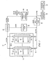
- FIGURE 1 is a block diagram of an apparatus 10 that includes a phased array antenna system 12.
- the antenna system 12 includes a plurality of identical modular parts that are commonly known as slats, two of which are depicted at 14 and 16.
- a feature of the present invention involves techniques for controlling cooling the slats 14 and 16, so as to remove appropriate amounts of heat generated by electronic circuitry therein.
- the electronic circuitry within the antenna system 12 has a known configuration, and is therefore not illustrated and described here in detail. Instead, the circuitry is described only briefly here, to an extent that facilitates an understanding of the present invention.
- the antenna system 12 includes a two-dimensional array of not-illustrated antenna elements, each column of the antenna elements being provided on a respective one of the slats, including the slats 14 and 16.
- Each slat includes separate and not-illustrated transmit/receive circuitry for each antenna element. It is the transmit/receive circuitry which generates most of the heat that needs to be withdrawn from the slats.
- the heat generated by the transmit/receive circuitry is shown diagrammatically in FIGURE 1, for example by the arrows at 18 and 20.
- Each of the slats is configured so that the heat it generates is transferred to a tube 22 or 24 extending through that slat.
- the tube 22 or 24 could be a channel or passageway extending through the slat, instead of a physically separate tube.
- a fluid coolant flows through each of the tubes 22 and 24. As discussed later, this fluid coolant is a two-phase coolant, which enters the slat in liquid form. Absorption of heat from the slat causes part or all of the liquid coolant to boil and vaporize, such that some or all of the coolant leaving the slats 14 and 16 is in its vapor phase.
- This departing coolant then flows successively through a separator 26, a heat exchanger 28, a pump 30, and a respective one of two orifices 32 and 34, in order to again reach the inlet ends of the tubes 22 and 24.
- the pump 30 causes the coolant to circulate around the endless loop shown in FIGURE 1. In the embodiment of FIGURE 1, the pump 30 consumes only about 0.1 kilowatts to 2.0 kilowatts of power.
- Separator 26 separates the vaporized portion of the liquid coolant flowing through tubes 22 and 24 from the unvaporized liquid portion.
- the vaporized portion is provided to heat exchanger 28, and the liquid portion is provided at separator pump 36.
- Separator pump 36 receives the liquid portion of the coolant that has not vaporized in tubes 22 and 24 circulates this fluid back through tubes 22 and 24 via orifices 32 and 34.
- the orifices 32 and 34 facilitate proper partitioning of the coolant among the respective slats, and also help to create a large pressure drop between the output of the pump 30 and the tubes 18 and 20 in which the coolant vaporizes. It is possible for the orifices 32 and 34 to have the same size, or to have different sizes in order to partition the coolant in a proportional manner which facilitates a desired cooling profile.
- Ambient air or liquid 38 is caused to flow through the heat exchanger 28, for example by a not-illustrated fan of a known type. Alternatively, if the apparatus 10 was on a ship, the flow 38 could be ambient seawater.
- the heat exchanger 28 transfers heat from the coolant to the air flow 38. The heat exchanger 28 thus cools the coolant, thereby causing any portion of the coolant which is in the vapor phase to condense back into its liquid phase.
- the liquid coolant exiting the heat exchanger 28 is supplied to the expansion reservoir 40.
- the expansion reservoir 40 is provided in order to take up the volume of liquid coolant that is displaced when some or all of the coolant in the system changes from its liquid phase to its vapor phase.
- the amount of the coolant that is in its vapor phase can vary over time, due in part to the fact that the amount of heat being produced by the antenna system 12 will vary over time, as the antenna system operates in various operational modes.
- Pressure controller 42 maintains the coolant at a desired subambient pressure in portions of the cooling loop downstream of the orifices 32 and 34 and upstream of the pump 30, as described in greater detail in conjunction with FIGURES 2 and 3.
- the ambient air pressure will be that of atmospheric air, which at sea level is 14.7 pounds per square inch area (psia).
- this subambient pressure may need to be adjusted to allow greater or lesser amounts of heat transfer from slats 18 and 20 at a desired temperature.
- slats 18 and 20 are maintained at a desired temperature by feeding back the pressure of the coolant as it exits passageways 22 and 24.
- pressure controller 42 may respond by raising or lowering the pressure of the coolant, which affects the boiling temperature of the coolant and therefore the rate of heat transfer. By feeding back the coolant pressure, as opposed to the temperature of the slats, associated thermal delay is eliminated from the control loop, permitting direct control of pressure without taking into account the thermal delay.
- one highly efficient technique for removing heat from a surface is to boil and vaporize a liquid which is in contact with the surface. As the liquid vaporizes, it inherently absorbs heat. The amount of heat that can be absorbed per unit volume of a liquid is commonly known as the latent heat of vaporization of the liquid. The higher the latent heat of vaporization, the larger the amount of heat that can be absorbed per unit volume of liquid being vaporized.
- the coolant used in the disclosed embodiment of FIGURE 1 is water. Water absorbs a substantial amount of heat as it vaporizes, and thus has a very high latent heat of vaporization. However, water boils at a temperature of 100oC at atmospheric pressure of 14.7 psia. In order to provide suitable cooling for an electronic apparatus such as the phased array antenna system 12, the coolant needs to boil at a temperature in the range of approximately 60oC. When water is subjected to a subambient pressure of about 3 psia, its boiling temperature decreases to approximately 60oC. Thus, in the embodiment of FIGURE 1, the orifices 32 and 34 permit the coolant pressure downstream from them to be substantially less than the coolant pressure between the pump 30 and the orifices 32 and 34.
- Water flowing from the pump 30 to the orifices 32 and 34 has a temperature of approximately 60oC to 65oC, and a pressure in the range of approximately 15 psia to 100 psia. After passing through the orifices 32 and 34, the water will still have a temperature of approximately 60oC to 65oC, but will have a much lower pressure, in the range about 2 psia to 8 psia. Due to this reduced pressure, some or all of the water will boil as it passes through and absorbs heat from the tubes 22 and 24, and some or all of the water will thus vaporize. After exiting the slats, the water vapor (and any remaining liquid water) will still have the reduced pressure of about 2 psia to 8 psia.
- the air flow 38 has a temperature less than a specified maximum of 55oC, and typically has an ambient temperature below 40oC.
- any portion of the water which is in its vapor phase will condense, such that all of the coolant water will be in liquid form when it exits the heat exchanger 28.
- This liquid will have a temperature of approximately 60oC to 65oC, and will still be at the subambient pressure of approximately 2 psia to 8 psia.
- This liquid coolant will then flow to the pump 30 with a tee connection prior to the expansion reservoir 40.
- the pump 30 will have the effect of increasing the pressure of the coolant water, to a value in the range of approximately 15 psia to 100 psia, as mentioned earlier.
- FIGURE 1 operates without any refrigeration system.
- high-power electronic circuitry such as that utilized in the phased array antenna system 12
- the absence of a refrigeration system can result in a very significant reduction in the size, weight, and power consumption of the structure provided to cool the antenna system.
- the coolant used in the embodiment of FIGURE 1 is water.
- other coolants including but not limited to methanol, a fluorinert, a mixture of water and methanol, or a mixture of water and ethylene glycol (WEGL).
- These alternative coolants each have a latent heat of vaporization less than that of water, which means that a larger volume of coolant must be flowing in order to obtain the same cooling effect that can be obtained with water.
- a fluorinert has a latent heat of vaporization which is typically about 5% of the latent heat of vaporization of water.
- the volume or flow rate of the fluorinert would have to be approximately 20 times the given volume or flow rate of water.
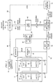
- FIGURE 2 is a block diagram of the apparatus 10 of FIGURE 1 showing additional details related to the control of apparatus 10.
- FIGURE 2 additionally illustrates a pressure transducer 44 that measures the pressure of the coolant within tubes 22 and 24.
- pressure transducer 44 measures the pressure at which coolant within tubes 22 and 24 boils.
- any transducer capable of providing an indication of the pressure at which coolant within tubes 22 and 24 boils may be utilized.
- One example of such an alternative transducer is a temperature transducer, because the pressure at which coolant in tubes 22 and 24 boils may be determined by the temperature of such coolant.
- Temperature transducer 44 provides a signal 46 indicative of the pressure coolant in tubes 22 and 24 to controller 42.
- Controller 42 controls pressure of coolant in tubes 22 and 24 by either introducing additional coolant or removing coolant from the portion of the control loop between tubes 22 and 24 and heat exchange pump 30.
- expansion reservoir 40 includes a pump motor 48 having a reversible shaft 50 driving a positive displacement charge pump 52. If it is determined that the pressure in tubes 22 and 24 needs to be increased, controller 42 commands (via command 60) the pump motor 48 to drive the positive displacement charge pump 52 to provide additional coolant to the coolant loop. If it is desired that the coolant pressure in tubes 22 and 24 be lowered, controller 42 commands pump motor 48 to drive positive displacement discharge pump 52 to remove coolant from the coolant loop and store it in a holding reservoir 54. Controller 42 also receives a level indication 56 indicative of the level of holding reservoir 54. Pump meter feeds back its speed to controller 42 via signal 62.
- controller 42 also receives a signal 58 indicative of the heat load of base array antenna system 12. Because the relationship between the temperature of antenna array 12 and the pressure within tubes 22 and 24 depends upon the amount of heat being generated by antenna array 12, this signal may be utilized by controller 42 to determine whether the pressure in the cooling system loop should be increased or decreased. However, controller 42 may be appropriately programmed to provide the correct pressure adjustment based upon anticipated heat loads without receiving an indication of the actual heat load of antenna system 12. By controlling the temperature of antenna array system 12 through feedback and control of the pressure of the coolant in tubes 22 and 24, control loop complications associated with the thermal delay involved in feeding back temperature (and associated stability problems) can be avoided.
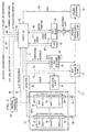
- FIGURE 3 is a block diagram of the system of FIGURE 1 showing yet even further details related to the control of apparatus 10.
- controller 42 receives a plurality of additional signals. These signals include a slat temperature level set 64, an ambient temperature 66, an ambient air pressure 68, slat temperatures 70, heat exchanger temperature and pressures 70, and a fan speed 74.
- controller 42 also is shown as generating a plurality of additional signals, including a separator pump control signal 76, a heat exchange pump control signal 78, and a fan control signal 80.
- Slat temperature level signal 64 presents a desired temperature for slats 18 and 20.
- the slat temperature level is set and controller 42 utilizes the desired set level in determining any appropriate changes to the pressure of the coolant in tubes 22 and 24 to maintain this temperature. Such calculations may also include the heat load indicator 58.
- the ambient air temperature signal 66 is used to set the speed of a fan 82 to ensure that the correct air mass flow rate through heat exchanger 28 occurs for a specific heat load relative to the temperature of the ambient air entering the heat exchanger 28.
- the ambient air pressure may vary as a function of the operating altitude of apparatus 10.
- Signal 68 which is indicative of the ambient air pressure is used to set the fan 82 motor speed to ensure the correct air mass flow through the heat exchanger regardless of altitude.
- the ambient air pressure signal 68 is also used to compensate for pressure variations in the holding reservoir 54 until an optimum pressure is maintained.
- the heat exchanger temperatures, represented by numeral 72, at the heat exchanger inlet and outlet are provided to controller 42 to indicate the performance of the heat exchanger and to see if the heat exchanger 28 is reaching its maximum capacity, as indicated by the outlet temperature being close to or the same as the inlet temperature.
- the associated heat exchanger pressures, also represented by reference numeral 72, is provided to controller 42 on both sides of the heat exchanger 38. These pressures are used to determine the air mass flow rate through the heat exchanger and determine the desired fan motor speed. In addition, these pressures are used with the measured fan speed to assess if the heat exchanger 28 is getting clogged with trash or debris.
- Fan control signal 80 and the associated fan speed 74 are provided by and to controller 42 to control the fan speed to regulate the air mass flow through heat exchanger 28.
- Slat temperature level set 64 is a signal provided to controller 42 that informs controller 42 that it should raise the saturation pressure in the loop to raise its boiling temperature during periods of low heat load. This is performed to hold the temperature of the slat assembly constant over a range of heat loads.
- Controller 42 also generates halt and status reporting signals, represented collectively by reference numeral 84. Signals 84 communicate the operational status of the cooling system and reports whether the cooling system is operating within set limits based on the heat load being removed. Controller 42 also reports if any alarm or shutdown limits have been reached.
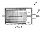
- FIGURE 4 is a diagram of an example linear actuated bellows-like reservoir 86 that may be used as an alternative approach for moving fluid into or out of the control loop to control the loop's pressure.
- Reservoir 86 includes a linear actuator 88 that may pull or push on a free end 90 of the bellows 92 to evacuate the loop or to let coolant flow back into the loop.
- Reservoir 86 combines the functions of holding reservoir 54 and dispositive displacement charge pump 52.
Landscapes
- Engineering & Computer Science (AREA)
- Physics & Mathematics (AREA)
- Mechanical Engineering (AREA)
- Thermal Sciences (AREA)
- General Engineering & Computer Science (AREA)
- Cooling Or The Like Of Semiconductors Or Solid State Devices (AREA)
Applications Claiming Priority (2)
| Application Number | Priority Date | Filing Date | Title |
|---|---|---|---|
| US10/853,038 US20050262861A1 (en) | 2004-05-25 | 2004-05-25 | Method and apparatus for controlling cooling with coolant at a subambient pressure |
| US853038 | 2004-05-25 |
Publications (2)
| Publication Number | Publication Date |
|---|---|
| EP1601043A2 true EP1601043A2 (fr) | 2005-11-30 |
| EP1601043A3 EP1601043A3 (fr) | 2006-10-11 |
Family
ID=34941341
Family Applications (1)
| Application Number | Title | Priority Date | Filing Date |
|---|---|---|---|
| EP05253020A Withdrawn EP1601043A3 (fr) | 2004-05-25 | 2005-05-17 | Procédé et dispositif pour refroidir avec un fluide réfrigérant à pression sous-ambiante |
Country Status (2)
| Country | Link |
|---|---|
| US (1) | US20050262861A1 (fr) |
| EP (1) | EP1601043A3 (fr) |
Cited By (7)
| Publication number | Priority date | Publication date | Assignee | Title |
|---|---|---|---|---|
| WO2007102978A1 (fr) * | 2006-03-08 | 2007-09-13 | Raytheon Company | Système et méthode de refroidissement d'un centre de données fondé sur un serveur grâce à un refroidissement au dessous de la température ambiante |
| WO2007133357A3 (fr) * | 2006-05-02 | 2008-03-06 | Raytheon Co | Procédé et appareil de refroidissement de composants électroniques par un fluide de refroidissement à une pression inférieure à la pression ambiante |
| WO2009039057A1 (fr) * | 2007-09-21 | 2009-03-26 | Raytheon Company | Cycle supérieur pour un système de refroidissement subatmosphérique |
| WO2009039128A1 (fr) * | 2007-09-17 | 2009-03-26 | Raytheon Company | Système de refroidissement pour tubes à vide de grande puissance |
| WO2009108572A1 (fr) * | 2008-02-25 | 2009-09-03 | Raytheon Company | Système et procédé de refroidissement d’une structure thermogène |
| US7907409B2 (en) | 2008-03-25 | 2011-03-15 | Raytheon Company | Systems and methods for cooling a computing component in a computing rack |
| EP2000753A3 (fr) * | 2007-03-22 | 2012-02-15 | Raytheon Company | Système et procédé de séparation de composants d'un agent de refroidissement fluide pour refroidir une structure |
Families Citing this family (4)
| Publication number | Priority date | Publication date | Assignee | Title |
|---|---|---|---|---|
| US20070119572A1 (en) | 2005-11-30 | 2007-05-31 | Raytheon Company | System and Method for Boiling Heat Transfer Using Self-Induced Coolant Transport and Impingements |
| EP2411746A2 (fr) * | 2009-03-27 | 2012-02-01 | Carrier Corporation | Système et procédé pour contrôler un système de réfrigération |
| US20120325436A1 (en) | 2011-06-27 | 2012-12-27 | Shedd Timothy A | High efficiency thermal management system |
| KR102566875B1 (ko) * | 2022-10-07 | 2023-08-14 | 한화시스템 주식회사 | 안테나 냉각 장치 및 그 방법 |
Citations (2)
| Publication number | Priority date | Publication date | Assignee | Title |
|---|---|---|---|---|
| WO2003065781A1 (fr) * | 2002-01-29 | 2003-08-07 | Telefonaktiebolaget Lm Ericsson | Refroidissement d'armoires de materiel electronique |
| US6866092B1 (en) * | 1981-02-19 | 2005-03-15 | Stephen Molivadas | Two-phase heat-transfer systems |
Family Cites Families (75)
| Publication number | Priority date | Publication date | Assignee | Title |
|---|---|---|---|---|
| US1528619A (en) * | 1924-09-22 | 1925-03-03 | Paul Hofer | Production of cold glaze wall and floor plates |
| US1906422A (en) * | 1931-11-14 | 1933-05-02 | Atlantic Refining Co | Apparatus for heating |
| US2321964A (en) * | 1941-08-08 | 1943-06-15 | York Ice Machinery Corp | Purge system for refrigerative circuits |
| US2371443A (en) * | 1942-03-02 | 1945-03-13 | G & J Weir Ltd | Closed feed system for steam power plants |
| US3131548A (en) * | 1962-11-01 | 1964-05-05 | Worthington Corp | Refrigeration purge control |
| US3174540A (en) * | 1963-09-03 | 1965-03-23 | Gen Electric | Vaporization cooling of electrical apparatus |
| US3371298A (en) * | 1966-02-03 | 1968-02-27 | Westinghouse Electric Corp | Cooling system for electrical apparatus |
| US3609991A (en) * | 1969-10-13 | 1971-10-05 | Ibm | Cooling system having thermally induced circulation |
| US3586101A (en) * | 1969-12-22 | 1971-06-22 | Ibm | Cooling system for data processing equipment |
| US3774677A (en) * | 1971-02-26 | 1973-11-27 | Ibm | Cooling system providing spray type condensation |
| US3756903A (en) * | 1971-06-15 | 1973-09-04 | Wakefield Eng Inc | Closed loop system for maintaining constant temperature |
| US5333677A (en) * | 1974-04-02 | 1994-08-02 | Stephen Molivadas | Evacuated two-phase head-transfer systems |
| US3989102A (en) * | 1974-10-18 | 1976-11-02 | General Electric Company | Cooling liquid de-gassing system |
| US4019098A (en) * | 1974-11-25 | 1977-04-19 | Sundstrand Corporation | Heat pipe cooling system for electronic devices |
| US4301861A (en) * | 1975-06-16 | 1981-11-24 | Hudson Products Corporation | Steam condensing apparatus |
| US4003213A (en) * | 1975-11-28 | 1977-01-18 | Robert Bruce Cox | Triple-point heat pump |
| US4129180A (en) * | 1976-12-06 | 1978-12-12 | Hudson Products Corporation | Vapor condensing apparatus |
| US4169356A (en) * | 1978-02-27 | 1979-10-02 | Lloyd Kingham | Refrigeration purge system |
| GB2029250B (en) * | 1978-09-05 | 1982-10-27 | Apv Spiro Gills Ltd | Water chilling plant |
| JPS55118561A (en) * | 1979-03-05 | 1980-09-11 | Hitachi Ltd | Constant pressure type boiling cooler |
| US4511376A (en) * | 1980-04-07 | 1985-04-16 | Coury Glenn E | Method of separating a noncondensable gas from a condensable vapor |
| US4381817A (en) * | 1981-04-27 | 1983-05-03 | Foster Wheeler Energy Corporation | Wet/dry steam condenser |
| US4495988A (en) * | 1982-04-09 | 1985-01-29 | The Charles Stark Draper Laboratory, Inc. | Controlled heat exchanger system |
| US4794984A (en) * | 1986-11-10 | 1989-01-03 | Lin Pang Yien | Arrangement for increasing heat transfer coefficient between a heating surface and a boiling liquid |
| US4998181A (en) * | 1987-12-15 | 1991-03-05 | Texas Instruments Incorporated | Coldplate for cooling electronic equipment |
| US4851856A (en) * | 1988-02-16 | 1989-07-25 | Westinghouse Electric Corp. | Flexible diaphragm cooling device for microwave antennas |
| JPH06100408B2 (ja) * | 1988-09-09 | 1994-12-12 | 日本電気株式会社 | 冷却装置 |
| US4938280A (en) * | 1988-11-07 | 1990-07-03 | Clark William E | Liquid-cooled, flat plate heat exchanger |
| US5168919A (en) * | 1990-06-29 | 1992-12-08 | Digital Equipment Corporation | Air cooled heat exchanger for multi-chip assemblies |
| DE4118196C2 (de) * | 1990-06-29 | 1995-07-06 | Erno Raumfahrttechnik Gmbh | Verdampfungswärmetauscher |
| JPH0827109B2 (ja) * | 1990-07-12 | 1996-03-21 | 甲府日本電気株式会社 | 液体冷却装置 |
| US5128689A (en) * | 1990-09-20 | 1992-07-07 | Hughes Aircraft Company | Ehf array antenna backplate including radiating modules, cavities, and distributor supported thereon |
| CA2053055C (fr) * | 1990-10-11 | 1997-02-25 | Tsukasa Mizuno | Systeme de refroidissement par liquide pour boitiers lsi |
| US5148859A (en) * | 1991-02-11 | 1992-09-22 | General Motors Corporation | Air/liquid heat exchanger |
| US5067560A (en) * | 1991-02-11 | 1991-11-26 | American Standard Inc. | Condenser coil arrangement for refrigeration system |
| US5181395A (en) * | 1991-03-26 | 1993-01-26 | Donald Carpenter | Condenser assembly |
| NO915127D0 (no) * | 1991-12-27 | 1991-12-27 | Sinvent As | Kompresjonsanordning med variabelt volum |
| US5239443A (en) * | 1992-04-23 | 1993-08-24 | International Business Machines Corporation | Blind hole cold plate cooling system |
| US5501082A (en) * | 1992-06-16 | 1996-03-26 | Hitachi Building Equipment Engineering Co., Ltd. | Refrigeration purge and/or recovery apparatus |
| US5245839A (en) * | 1992-08-03 | 1993-09-21 | Industrial Technology Research Institute | Adsorption-type refrigerant recovery apparatus |
| US5261246A (en) * | 1992-10-07 | 1993-11-16 | Blackmon John G | Apparatus and method for purging a refrigeration system |
| US5493305A (en) * | 1993-04-15 | 1996-02-20 | Hughes Aircraft Company | Small manufacturable array lattice layers |
| US5507150A (en) * | 1994-02-04 | 1996-04-16 | Texas Instruments Incorporated | Expendable liquid thermal management system |
| US5515690A (en) * | 1995-02-13 | 1996-05-14 | Carolina Products, Inc. | Automatic purge supplement after chamber with adsorbent |
| US5960861A (en) * | 1995-04-05 | 1999-10-05 | Raytheon Company | Cold plate design for thermal management of phase array-radar systems |
| US6305463B1 (en) * | 1996-02-22 | 2001-10-23 | Silicon Graphics, Inc. | Air or liquid cooled computer module cold plate |
| US5605054A (en) * | 1996-04-10 | 1997-02-25 | Chief Havc Engineering Co., Ltd. | Apparatus for reclaiming refrigerant |
| US5701751A (en) * | 1996-05-10 | 1997-12-30 | Schlumberger Technology Corporation | Apparatus and method for actively cooling instrumentation in a high temperature environment |
| US5943211A (en) * | 1997-04-18 | 1999-08-24 | Raytheon Company | Heat spreader system for cooling heat generating components |
| US6052284A (en) * | 1996-08-06 | 2000-04-18 | Advantest Corporation | Printed circuit board with electronic devices mounted thereon |
| US5841564A (en) * | 1996-12-31 | 1998-11-24 | Motorola, Inc. | Apparatus for communication by an electronic device and method for communicating between electronic devices |
| US5806322A (en) * | 1997-04-07 | 1998-09-15 | York International | Refrigerant recovery method |
| US5815370A (en) * | 1997-05-16 | 1998-09-29 | Allied Signal Inc | Fluidic feedback-controlled liquid cooling module |
| US5862675A (en) * | 1997-05-30 | 1999-01-26 | Mainstream Engineering Corporation | Electrically-driven cooling/heating system utilizing circulated liquid |
| US5818692A (en) * | 1997-05-30 | 1998-10-06 | Motorola, Inc. | Apparatus and method for cooling an electrical component |
| US5950717A (en) * | 1998-04-09 | 1999-09-14 | Gea Power Cooling Systems Inc. | Air-cooled surface condenser |
| US6055154A (en) * | 1998-07-17 | 2000-04-25 | Lucent Technologies Inc. | In-board chip cooling system |
| US6018192A (en) * | 1998-07-30 | 2000-01-25 | Motorola, Inc. | Electronic device with a thermal control capability |
| US6297775B1 (en) * | 1999-09-16 | 2001-10-02 | Raytheon Company | Compact phased array antenna system, and a method of operating same |
| US6519955B2 (en) * | 2000-04-04 | 2003-02-18 | Thermal Form & Function | Pumped liquid cooling system using a phase change refrigerant |
| US6292364B1 (en) * | 2000-04-28 | 2001-09-18 | Raytheon Company | Liquid spray cooled module |
| US6366462B1 (en) * | 2000-07-18 | 2002-04-02 | International Business Machines Corporation | Electronic module with integral refrigerant evaporator assembly and control system therefore |
| CA2329408C (fr) * | 2000-12-21 | 2007-12-04 | Long Manufacturing Ltd. | Echangeur de chaleur a plaques a ailettes |
| US6594479B2 (en) * | 2000-12-28 | 2003-07-15 | Lockheed Martin Corporation | Low cost MMW transceiver packaging |
| US6498725B2 (en) * | 2001-05-01 | 2002-12-24 | Mainstream Engineering Corporation | Method and two-phase spray cooling apparatus |
| US6976527B2 (en) * | 2001-07-17 | 2005-12-20 | The Regents Of The University Of California | MEMS microcapillary pumped loop for chip-level temperature control |
| US6529377B1 (en) * | 2001-09-05 | 2003-03-04 | Microelectronic & Computer Technology Corporation | Integrated cooling system |
| JP3946018B2 (ja) * | 2001-09-18 | 2007-07-18 | 株式会社日立製作所 | 液冷却式回路装置 |
| US6942018B2 (en) * | 2001-09-28 | 2005-09-13 | The Board Of Trustees Of The Leland Stanford Junior University | Electroosmotic microchannel cooling system |
| US7000691B1 (en) * | 2002-07-11 | 2006-02-21 | Raytheon Company | Method and apparatus for cooling with coolant at a subambient pressure |
| US6708511B2 (en) * | 2002-08-13 | 2004-03-23 | Delaware Capital Formation, Inc. | Cooling device with subcooling system |
| US6957550B2 (en) * | 2003-05-19 | 2005-10-25 | Raytheon Company | Method and apparatus for extracting non-condensable gases in a cooling system |
| US6827135B1 (en) * | 2003-06-12 | 2004-12-07 | Gary W. Kramer | High flux heat removal system using jet impingement of water at subatmospheric pressure |
| US6952345B2 (en) * | 2003-10-31 | 2005-10-04 | Raytheon Company | Method and apparatus for cooling heat-generating structure |
| US6952346B2 (en) * | 2004-02-24 | 2005-10-04 | Isothermal Systems Research, Inc | Etched open microchannel spray cooling |
-
2004
- 2004-05-25 US US10/853,038 patent/US20050262861A1/en not_active Abandoned
-
2005
- 2005-05-17 EP EP05253020A patent/EP1601043A3/fr not_active Withdrawn
Patent Citations (2)
| Publication number | Priority date | Publication date | Assignee | Title |
|---|---|---|---|---|
| US6866092B1 (en) * | 1981-02-19 | 2005-03-15 | Stephen Molivadas | Two-phase heat-transfer systems |
| WO2003065781A1 (fr) * | 2002-01-29 | 2003-08-07 | Telefonaktiebolaget Lm Ericsson | Refroidissement d'armoires de materiel electronique |
Cited By (10)
| Publication number | Priority date | Publication date | Assignee | Title |
|---|---|---|---|---|
| WO2007102978A1 (fr) * | 2006-03-08 | 2007-09-13 | Raytheon Company | Système et méthode de refroidissement d'un centre de données fondé sur un serveur grâce à un refroidissement au dessous de la température ambiante |
| WO2007133357A3 (fr) * | 2006-05-02 | 2008-03-06 | Raytheon Co | Procédé et appareil de refroidissement de composants électroniques par un fluide de refroidissement à une pression inférieure à la pression ambiante |
| US7908874B2 (en) | 2006-05-02 | 2011-03-22 | Raytheon Company | Method and apparatus for cooling electronics with a coolant at a subambient pressure |
| US8490418B2 (en) | 2006-05-02 | 2013-07-23 | Raytheon Company | Method and apparatus for cooling electronics with a coolant at a subambient pressure |
| EP2000753A3 (fr) * | 2007-03-22 | 2012-02-15 | Raytheon Company | Système et procédé de séparation de composants d'un agent de refroidissement fluide pour refroidir une structure |
| US8651172B2 (en) | 2007-03-22 | 2014-02-18 | Raytheon Company | System and method for separating components of a fluid coolant for cooling a structure |
| WO2009039128A1 (fr) * | 2007-09-17 | 2009-03-26 | Raytheon Company | Système de refroidissement pour tubes à vide de grande puissance |
| WO2009039057A1 (fr) * | 2007-09-21 | 2009-03-26 | Raytheon Company | Cycle supérieur pour un système de refroidissement subatmosphérique |
| WO2009108572A1 (fr) * | 2008-02-25 | 2009-09-03 | Raytheon Company | Système et procédé de refroidissement d’une structure thermogène |
| US7907409B2 (en) | 2008-03-25 | 2011-03-15 | Raytheon Company | Systems and methods for cooling a computing component in a computing rack |
Also Published As
| Publication number | Publication date |
|---|---|
| EP1601043A3 (fr) | 2006-10-11 |
| US20050262861A1 (en) | 2005-12-01 |
Similar Documents
| Publication | Publication Date | Title |
|---|---|---|
| EP1601043A2 (fr) | Procédé et dispositif pour refroidir avec un fluide réfrigérant à pression sous-ambiante | |
| US7254957B2 (en) | Method and apparatus for cooling with coolant at a subambient pressure | |
| US6775996B2 (en) | Systems and methods for temperature control | |
| US7607475B2 (en) | Apparatus for cooling with coolant at subambient pressure | |
| CA2490660C (fr) | Machine trans-critique a compression de vapeur et methode de fonctionnement, y compris cuve de stockage de frigorigene et dispositif a decompression non variable | |
| EP2000753B1 (fr) | Système et procédé de séparation de composants d'un agent de refroidissement fluide pour refroidir une structure | |
| KR101453924B1 (ko) | 정밀 온도 조정 장치 | |
| EP2203696B1 (fr) | Système de refroidissement | |
| RU2660723C1 (ru) | Способ управления эжекторным блоком переменной производительности | |
| US20150135746A1 (en) | Parallel evaporator circuit with balanced flow | |
| US9677822B2 (en) | Efficient temperature forcing of semiconductor devices under test | |
| CN111457766B (zh) | 一种基于沸腾传热的牵引变流器冷却系统 | |
| WO2006087794A1 (fr) | Systeme de refroidissement par circulation pour cable cryogenique | |
| US11448434B1 (en) | Thermal management systems | |
| US20140209288A1 (en) | Cooling technique | |
| EP1796447B1 (fr) | Système et méthode pour un chassis électronique, électronique montée dans une baie avec un système de refroidissement intégré sousambiant | |
| EP2201311B1 (fr) | Système et procédé de refroidissement de structures présentant à la fois un état actif et un état inactif | |
| US7337625B1 (en) | Thermal control systems for process tools requiring operation over wide temperature ranges | |
| JP2006057925A (ja) | 2相流体ループ式熱輸送装置 | |
| CN107992127B (zh) | 基于动态热容滤波的高精度恒温循环冷却水装置 | |
| JP2006038302A (ja) | 冷却装置及び冷却制御方法 | |
| JP2732763B2 (ja) | 二相流体ループ式排熱装置 | |
| EP0815402B1 (fr) | Refrigerant | |
| JP2682629B2 (ja) | Lsiの冷却装置 | |
| JP2508640B2 (ja) | 冷却装置 |
Legal Events
| Date | Code | Title | Description |
|---|---|---|---|
| PUAI | Public reference made under article 153(3) epc to a published international application that has entered the european phase |
Free format text: ORIGINAL CODE: 0009012 |
|
| AK | Designated contracting states |
Kind code of ref document: A2 Designated state(s): AT BE BG CH CY CZ DE DK EE ES FI FR GB GR HU IE IS IT LI LT LU MC NL PL PT RO SE SI SK TR |
|
| AX | Request for extension of the european patent |
Extension state: AL BA HR LV MK YU |
|
| PUAL | Search report despatched |
Free format text: ORIGINAL CODE: 0009013 |
|
| AK | Designated contracting states |
Kind code of ref document: A3 Designated state(s): AT BE BG CH CY CZ DE DK EE ES FI FR GB GR HU IE IS IT LI LT LU MC NL PL PT RO SE SI SK TR |
|
| AX | Request for extension of the european patent |
Extension state: AL BA HR LV MK YU |
|
| 17P | Request for examination filed |
Effective date: 20070402 |
|
| AKX | Designation fees paid |
Designated state(s): AT BE BG CH CY CZ DE DK EE ES FI FR GB GR HU IE IS IT LI LT LU MC NL PL PT RO SE SI SK TR |
|
| 17Q | First examination report despatched |
Effective date: 20071024 |
|
| STAA | Information on the status of an ep patent application or granted ep patent |
Free format text: STATUS: THE APPLICATION IS DEEMED TO BE WITHDRAWN |
|
| 18D | Application deemed to be withdrawn |
Effective date: 20141202 |