EP1600675A1 - Procédé et dispositif perfectionné de séparation en lit mobile simulé - Google Patents
Procédé et dispositif perfectionné de séparation en lit mobile simulé Download PDFInfo
- Publication number
- EP1600675A1 EP1600675A1 EP05290968A EP05290968A EP1600675A1 EP 1600675 A1 EP1600675 A1 EP 1600675A1 EP 05290968 A EP05290968 A EP 05290968A EP 05290968 A EP05290968 A EP 05290968A EP 1600675 A1 EP1600675 A1 EP 1600675A1
- Authority
- EP
- European Patent Office
- Prior art keywords
- lines
- valve
- rotary valve
- fluids
- column
- Prior art date
- Legal status (The legal status is an assumption and is not a legal conclusion. Google has not performed a legal analysis and makes no representation as to the accuracy of the status listed.)
- Granted
Links
- 238000000034 method Methods 0.000 title claims abstract description 24
- 238000000926 separation method Methods 0.000 title abstract description 19
- 239000012530 fluid Substances 0.000 claims abstract description 46
- 239000000203 mixture Substances 0.000 claims abstract description 28
- 238000000605 extraction Methods 0.000 claims abstract description 17
- 239000007788 liquid Substances 0.000 claims abstract description 16
- 230000008569 process Effects 0.000 claims abstract description 15
- 238000010408 sweeping Methods 0.000 claims abstract description 10
- 150000001875 compounds Chemical class 0.000 claims abstract description 8
- 238000001179 sorption measurement Methods 0.000 claims abstract description 5
- 239000003463 adsorbent Substances 0.000 claims description 17
- 238000004891 communication Methods 0.000 claims description 12
- URLKBWYHVLBVBO-UHFFFAOYSA-N Para-Xylene Chemical group CC1=CC=C(C)C=C1 URLKBWYHVLBVBO-UHFFFAOYSA-N 0.000 claims description 7
- IVSZLXZYQVIEFR-UHFFFAOYSA-N m-xylene Chemical group CC1=CC=CC(C)=C1 IVSZLXZYQVIEFR-UHFFFAOYSA-N 0.000 claims description 6
- 238000002156 mixing Methods 0.000 claims description 6
- 238000011068 loading method Methods 0.000 claims description 5
- 150000004945 aromatic hydrocarbons Chemical class 0.000 claims description 2
- OKTJSMMVPCPJKN-UHFFFAOYSA-N Carbon Chemical compound [C] OKTJSMMVPCPJKN-UHFFFAOYSA-N 0.000 claims 1
- 229910052799 carbon Inorganic materials 0.000 claims 1
- 238000011010 flushing procedure Methods 0.000 claims 1
- 238000002347 injection Methods 0.000 abstract description 15
- 239000007924 injection Substances 0.000 abstract description 15
- 238000009795 derivation Methods 0.000 abstract description 9
- XTHFKEDIFFGKHM-UHFFFAOYSA-N Dimethoxyethane Chemical compound COCCOC XTHFKEDIFFGKHM-UHFFFAOYSA-N 0.000 abstract 3
- 230000007774 longterm Effects 0.000 description 6
- 239000003480 eluent Substances 0.000 description 5
- 241000287107 Passer Species 0.000 description 4
- 230000008901 benefit Effects 0.000 description 4
- 238000005516 engineering process Methods 0.000 description 4
- 125000003118 aryl group Chemical group 0.000 description 3
- 238000002079 electron magnetic resonance spectroscopy Methods 0.000 description 3
- 230000004907 flux Effects 0.000 description 3
- 239000000243 solution Substances 0.000 description 3
- 241000239290 Araneae Species 0.000 description 2
- 108091005515 EGF module-containing mucin-like hormone receptors Proteins 0.000 description 2
- YNQLUTRBYVCPMQ-UHFFFAOYSA-N Ethylbenzene Chemical compound CCC1=CC=CC=C1 YNQLUTRBYVCPMQ-UHFFFAOYSA-N 0.000 description 2
- 229930091371 Fructose Natural products 0.000 description 2
- RFSUNEUAIZKAJO-ARQDHWQXSA-N Fructose Chemical compound OC[C@H]1O[C@](O)(CO)[C@@H](O)[C@@H]1O RFSUNEUAIZKAJO-ARQDHWQXSA-N 0.000 description 2
- 239000005715 Fructose Substances 0.000 description 2
- WQZGKKKJIJFFOK-GASJEMHNSA-N Glucose Natural products OC[C@H]1OC(O)[C@H](O)[C@@H](O)[C@@H]1O WQZGKKKJIJFFOK-GASJEMHNSA-N 0.000 description 2
- 230000000694 effects Effects 0.000 description 2
- 239000008103 glucose Substances 0.000 description 2
- 239000002904 solvent Substances 0.000 description 2
- 238000012546 transfer Methods 0.000 description 2
- 108091036429 KCNQ1OT1 Proteins 0.000 description 1
- 241001080024 Telles Species 0.000 description 1
- 240000008042 Zea mays Species 0.000 description 1
- 150000001336 alkenes Chemical class 0.000 description 1
- 125000004432 carbon atom Chemical group C* 0.000 description 1
- 239000011248 coating agent Substances 0.000 description 1
- 238000000576 coating method Methods 0.000 description 1
- 230000001276 controlling effect Effects 0.000 description 1
- 125000000853 cresyl group Chemical class C1(=CC=C(C=C1)C)* 0.000 description 1
- 230000001627 detrimental effect Effects 0.000 description 1
- 230000037213 diet Effects 0.000 description 1
- 235000005911 diet Nutrition 0.000 description 1
- 238000004821 distillation Methods 0.000 description 1
- 230000009977 dual effect Effects 0.000 description 1
- 229920001971 elastomer Polymers 0.000 description 1
- 239000000806 elastomer Substances 0.000 description 1
- 235000021183 entrée Nutrition 0.000 description 1
- 230000002349 favourable effect Effects 0.000 description 1
- 239000000945 filler Substances 0.000 description 1
- 239000002184 metal Substances 0.000 description 1
- 229910052751 metal Inorganic materials 0.000 description 1
- 230000004048 modification Effects 0.000 description 1
- 238000012986 modification Methods 0.000 description 1
- 239000003607 modifier Substances 0.000 description 1
- 230000003287 optical effect Effects 0.000 description 1
- 238000004064 recycling Methods 0.000 description 1
- 230000009467 reduction Effects 0.000 description 1
- 230000001105 regulatory effect Effects 0.000 description 1
- 230000035945 sensitivity Effects 0.000 description 1
- 239000000126 substance Substances 0.000 description 1
- 238000011144 upstream manufacturing Methods 0.000 description 1
Images
Classifications
-
- B—PERFORMING OPERATIONS; TRANSPORTING
- B01—PHYSICAL OR CHEMICAL PROCESSES OR APPARATUS IN GENERAL
- B01D—SEPARATION
- B01D15/00—Separating processes involving the treatment of liquids with solid sorbents; Apparatus therefor
- B01D15/08—Selective adsorption, e.g. chromatography
-
- C—CHEMISTRY; METALLURGY
- C07—ORGANIC CHEMISTRY
- C07C—ACYCLIC OR CARBOCYCLIC COMPOUNDS
- C07C7/00—Purification; Separation; Use of additives
- C07C7/12—Purification; Separation; Use of additives by adsorption, i.e. purification or separation of hydrocarbons with the aid of solids, e.g. with ion-exchangers
-
- B—PERFORMING OPERATIONS; TRANSPORTING
- B01—PHYSICAL OR CHEMICAL PROCESSES OR APPARATUS IN GENERAL
- B01D—SEPARATION
- B01D15/00—Separating processes involving the treatment of liquids with solid sorbents; Apparatus therefor
-
- B—PERFORMING OPERATIONS; TRANSPORTING
- B01—PHYSICAL OR CHEMICAL PROCESSES OR APPARATUS IN GENERAL
- B01D—SEPARATION
- B01D53/00—Separation of gases or vapours; Recovering vapours of volatile solvents from gases; Chemical or biological purification of waste gases, e.g. engine exhaust gases, smoke, fumes, flue gases, aerosols
- B01D53/02—Separation of gases or vapours; Recovering vapours of volatile solvents from gases; Chemical or biological purification of waste gases, e.g. engine exhaust gases, smoke, fumes, flue gases, aerosols by adsorption, e.g. preparative gas chromatography
- B01D53/04—Separation of gases or vapours; Recovering vapours of volatile solvents from gases; Chemical or biological purification of waste gases, e.g. engine exhaust gases, smoke, fumes, flue gases, aerosols by adsorption, e.g. preparative gas chromatography with stationary adsorbents
- B01D53/0407—Constructional details of adsorbing systems
- B01D53/0423—Beds in columns
-
- B—PERFORMING OPERATIONS; TRANSPORTING
- B01—PHYSICAL OR CHEMICAL PROCESSES OR APPARATUS IN GENERAL
- B01D—SEPARATION
- B01D15/00—Separating processes involving the treatment of liquids with solid sorbents; Apparatus therefor
- B01D15/08—Selective adsorption, e.g. chromatography
- B01D15/10—Selective adsorption, e.g. chromatography characterised by constructional or operational features
- B01D15/18—Selective adsorption, e.g. chromatography characterised by constructional or operational features relating to flow patterns
- B01D15/1864—Selective adsorption, e.g. chromatography characterised by constructional or operational features relating to flow patterns using two or more columns
- B01D15/1871—Selective adsorption, e.g. chromatography characterised by constructional or operational features relating to flow patterns using two or more columns placed in series
-
- B—PERFORMING OPERATIONS; TRANSPORTING
- B01—PHYSICAL OR CHEMICAL PROCESSES OR APPARATUS IN GENERAL
- B01D—SEPARATION
- B01D2259/00—Type of treatment
- B01D2259/40—Further details for adsorption processes and devices
- B01D2259/40003—Methods relating to valve switching
- B01D2259/40005—Methods relating to valve switching using rotary valves
-
- B—PERFORMING OPERATIONS; TRANSPORTING
- B01—PHYSICAL OR CHEMICAL PROCESSES OR APPARATUS IN GENERAL
- B01D—SEPARATION
- B01D2259/00—Type of treatment
- B01D2259/40—Further details for adsorption processes and devices
- B01D2259/414—Further details for adsorption processes and devices using different types of adsorbents
- B01D2259/4141—Further details for adsorption processes and devices using different types of adsorbents within a single bed
- B01D2259/4145—Further details for adsorption processes and devices using different types of adsorbents within a single bed arranged in series
- B01D2259/4146—Contiguous multilayered adsorbents
-
- Y—GENERAL TAGGING OF NEW TECHNOLOGICAL DEVELOPMENTS; GENERAL TAGGING OF CROSS-SECTIONAL TECHNOLOGIES SPANNING OVER SEVERAL SECTIONS OF THE IPC; TECHNICAL SUBJECTS COVERED BY FORMER USPC CROSS-REFERENCE ART COLLECTIONS [XRACs] AND DIGESTS
- Y10—TECHNICAL SUBJECTS COVERED BY FORMER USPC
- Y10T—TECHNICAL SUBJECTS COVERED BY FORMER US CLASSIFICATION
- Y10T436/00—Chemistry: analytical and immunological testing
- Y10T436/11—Automated chemical analysis
Definitions
- a simulated moving bed has at least three zones chromatographically, advantageously four or five, each of these zones being constituted by at least one bed or a section of column.
- a point of injection of a charge to be split there is either a point of injection of a charge to be split, either an injection point of an eluent or desorbent, or a point to extract an extract between the eluent injection point and the injection point of the charge which is located downstream (considering the direction of circulation of the eluent), ie a point of withdrawal of a raffinate between each injection point of the mixture and the point of eluent injection which is located downstream when considering the direction of circulation eluent.
- Multi-channel rotary valve devices and their operation are described in particular in patents US 3,040,777, US 3,422,848, US 4,614,204 and US Pat. 4633904.
- each of the beds requires a collection of the flow coming from the bed preceding (main fluid flowing along the main axis of the column), the possibility to inject an auxiliary fluid or secondary fluid while mixing the best these two fluids, or the possibility of taking a part of the fluid collected, to extract it to send it outside the device and also to redistribute fluid on the next bed.
- distribution chambers Ci injection / extraction
- injection / extraction are used which may be separate or common with the mixing chambers.
- a generic problem of all SMB devices is to minimize the pollution generated by the liquid in the different zones and volumes fluid supply and withdrawal circuits, chambers Ci, and in EMRs, during changes in feed and withdrawal points during the course of the operation of the SMB. Indeed, when, during the sequence of operation, a line, chamber, or power supply area of an EMR is no longer swept by a process fluid, it becomes a dead zone in which the liquid stagnates, and is only restarted when another process fluid is flowing through it again. Since, due to the operation of the SMB, it is then a fluid of process that is different, the liquid of the dead zone is necessarily displaced by a liquid of significantly different composition. The mixture, or the circulation at short time span of fluids of significantly different compositions introduced therefore a disturbance compared to the ideal operation, for which the Discontinuities of composition are to be avoided.
- Another problem may lie in the possible recirculations between different areas of the same plateau, which then also induces a disturbance compared to the ideal operation.
- FIG. With regard to trays and DMEs, in some cases angular sectors as presented in US Pat. No. 6,537,451, FIG. are symmetric feed (spider), or parallel sectors such as cut into a circumference, as indicated in the US patent application 03 / 0.127.394, which are asymmetrically powered. Pie trays parallel are typically supported plateaus of high resistance and allow for a denser loading of the adsorbent. Moreover, the differential feed lengths between different points of the same sector fed by the same line are lower, which is favorable to operation of the SMB. On the other hand, their asymmetrical power supplies can increase sensitivity to internal recirculation.
- a first advantage of such a system is that the injection and secondary fluids are swept by liquid having a very similar composition of the displaced liquid since on the one hand the derivation comes of the neighboring plateau, and secondly that there is not punctual sweeping but substantially continuous.
- the flow rates in the derivations so that the transit speed in each derivation is substantially the same as the speed of advancement of the concentration gradient in the main stream of the SMB.
- a second advantage of this system with substantially permanent scans is that it allows to suppress the effects of possible recirculations between areas of the same plateau due to small differences in pressure drops.
- SMB simulated moving bed separation device with a multi-way rotary valve.
- This SMB device with a multi-way rotary valve makes it possible to perform an efficient scanning of dead zones of the "long-term type with a low or no concentration gradient".
- Another object of the invention is that this device is compatible with existing multi-channel rotary valve technologies, without requiring modification of this valve, and can be adapted to existing units.
- Another object of the invention is that this device is compatible with many modes of implementation of the trays Pi and DME, in particular with DME parallel sectors and asymmetrical power supplies, and / or is compatible with a dense loading of the adsorbent.
- An essential element of the device according to the invention consists in installing around a multi-way rotary valve a plurality of bypass lines between adjacent outlets, which are connected in pairs, for the implementation of long-term scanning currents. at low or no concentration gradient. These bypass lines are typically located in close proximity to the rotary valve, so that most of the junction lines between the valve and the trays are scanned. This makes it possible to obtain a very efficient scanning of the dead zones and to avoid internal recirculation.
- the separation column comprises DME trays of parallel sector type and asymmetrical power supplies.
- the adsorbent is installed in dense loading. This makes it possible to use a larger quantity of adsorbent in a given column, and to increase the purity of the desired product and / or the charge rate of the SMB.
- the derivations Li, i + 1 connect two points on the lines Li and Li + 1 which are respectively in the first quarter, preferably the first tenth of the length and very preferably the first fiftieth of the length of the line Li, respectively Li + 1, the closest to the valve (RV), or in the immediate vicinity of (RV). This makes it possible to minimize the non-scanned portion of the Li lines.
- the device typically comprises means for controlling the sectioning means Vi, i + 1, coordinated with the position of the valve (RV) so that Vi, i + 1 is in the open position when neither Li nor Li + 1 is traveled. by a process fluid, except possibly when Li or Li + 1 is a line connected at the adsorber head, or that Li or Li + 1 is a line added to allow the evacuation of the last intermediate plateau towards the bottom of the adsorber, which is connected to the bottom outlet of the column.
- the operation of the taps does not interfere with the operation of the SMB device.
- the device may comprise scanning means constituted by the lines Li, j (which includes the elements which are arranged therein: valves Vi, j, possibly measuring system orifices and / or flow control etc. ..). In this case, there is no scanning outside the lines Li, j (the flush in / flush out sweeps are removed, which provides a simplification and a reduction of the concentration gradients used).
- the scanning means comprise the lines Li, j and additional means, internal to the rotary valve (VR), allowing the implementation circulation of a sweeping fluid for a period of between 1% and 15% of the time, between two lines Li and Lj not adjacent.
- the system of sweep is dual (long-range sweep with low concentration gradient or Null + relatively punctual scan flush in / flush out, which means in English: "Scan input / scan output”).
- This system is more complex but allows a scan of all lines and dead zones, including small sections of lines Li near (RV).
- punctual scanning can be performed at a rate reduced.
- the trays Pi comprise panels of distribution / extraction (DME) of the parallel sector type with feeds unsymmetrical.
- DME distribution / extraction
- these trays are supported (and not self-supporting) and have higher mechanical strength than sectored DME trays radial and symmetrical power supplies.
- Pi trays often include chambers Ci which are both distribution chambers (injection / extraction of secondary fluids), at the same time time than mixing.
- the invention also proposes a method for separating a desired product from from a mixture comprising it, comprising a device such as previously described in which scans of the Li, i + 1 branch lines are carried out during at least 40% of the time, which allows for a very efficient scanning of all types of trays Pi.
- the separation process can be used in particular to separate paraxylene, or metaxylene, as the desired product, from a feedstock aromatic hydrocarbons having 8 carbon atoms.
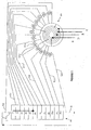
- FIG. 1 shows a simulated counter-current separation column (SC) comprising a plurality of trays P1, P2, P3, P4, P5, P6, P7, P8, P9, P10, P11, P12 (situated in the lower part of Corresponding adsorbent beds, not referenced
- SC counter-current separation column
- Each plate Pi is connected by a Li junction line (L0, L1, ..., L7, L8, ..., L11) to a multi-way rotary valve (RV) which allows to connect four streams of process fluids: D (solvent or desorbent), E (extract), R (raffinate), F (charge), with each of the beds of the column (SC).
- D solvent or desorbent
- E extract
- R raffinate
- F charge
- L12 can be added to connect the transfer line L11 towards the outlet of the adsorption column
- Another column, not shown, is also connected to the multi-way rotary valve (RV) by unrepresented lines L13, L14, ..., L24 on the second half of the periphery of this valve
- a line L25 can be added to connect the line of tra nsfer L24 to the output of the other column.
- the system operates in a closed loop, a main stream of liquid flowing downstream in the column (SC), is discharged via the line (2), circulates in a downward flow in the not shown column, then joins the column (SC) by the line (1).
- a multi-channel rotary valve has at least 4 inputs / outputs (the secondary fluids) and generally between 4 and 30) links to the trays by lines L1, ..., L5 etc. ..
- Each line Li connecting the rotary valve (RV) to an adsorbent bed (or plate Pi) can be placed in communication with the line connecting the rotary valve to the next bed or tray by means of a bypass line comprising a valve all or nothing arranged closer to the rotary valve, with the exception of the 2 lines respectively connecting the rotary valve to the entrance of the beds 12 and 24.
- a bypass line comprising a valve all or nothing arranged closer to the rotary valve, with the exception of the 2 lines respectively connecting the rotary valve to the entrance of the beds 12 and 24.
- the connection will be made by an additional line dotted to connect the line 12 and the downstream of the bed 12 and by a second additional line dashed to connect the line 24 (not shown) and the downstream of the bed 24.
- any branch line may also optionally include an orifice and / or a flow indicator or controller, and / or a control valve.
- each bypass valve Vi, i + 1 is numbered as a function of the bypass line Li, i + 1 connecting the lines Li and Li + 1: thus the bypass valve V1,2 is on the line L1 2, which connects the lines serving the beds 1 and 2 respectively, the bypass valve V15,16 is on the line L15,16 which connects the lines L15 and L16 respectively serving the beds 15 and 16, not shown in the figure.
- the principle of derivations on adjacent Li lines, as close as possible to the rotary valve (RV) is easily understood in FIG.
- valve Vi, i + 1 When the valve Vi, i + 1 is open, a minority flow of fluid flows from the plate Pi towards the plate Pi +1 via the lines Li, then Li, i + 1 (including Vi, i + 1 open), then Li + 1, establishing a low or zero concentration gradient scan.
Landscapes
- Chemical & Material Sciences (AREA)
- Analytical Chemistry (AREA)
- Organic Chemistry (AREA)
- Chemical Kinetics & Catalysis (AREA)
- Engineering & Computer Science (AREA)
- Oil, Petroleum & Natural Gas (AREA)
- Water Supply & Treatment (AREA)
- General Chemical & Material Sciences (AREA)
- Treatment Of Liquids With Adsorbents In General (AREA)
Abstract
Description
Les domaines concernés sont notamment, et de façon non exclusive :
- la séparation entre d'une part les paraffines normales et d'autre part les paraffines ramifiées, naphtènes, et aromatiques,
- la séparation oléfines / paraffines,
- la séparation du paraxylene des autres isomères en C8 aromatiques,
- la séparation du métaxylene des autres isomères en C8 aromatiques,
- la séparation de l'éthylbenzene des autres isomères en C8 aromatiques.
Au cours du procédé de séparation, on décale généralement dans un même sens, (aval ou amont, toujours en considérant le sens de circulation du fluide principal), les points d'injection et de soutirage d'au moins un tronçon ou colonne. C'est la base du principe d'un fonctionnement en lit mobile simulé.
Les dispositifs SMB comportent typiquement au moins une colonne (et souvent deux), des lits d'adsorbant disposés dans cette colonne, séparés par des plateaux Pi à chambre(s) Ci de distribution (injection/extraction) de fluides dans ou à partir des différents lits d'adsorbant, et des moyens coordonnés de distribution et d'extraction de fluides.
Chacun des plateaux Pi comprend typiquement une pluralité de panneaux distributeurs-mélangeurs-extracteurs ou « DME » alimentés par des lignes ou « araignées de distribution/extraction ».
Les moyens coordonnés de distribution et d'extraction de fluides sont le plus souvent de l'un des deux types suivants :
- soit, pour chaque plateau, une pluralité de vannes pour l' alimentation ou le soutirage des fluides, ces vannes étant typiquement situées au voisinage immédiat du plateau correspondant,
- soit une vanne rotative multi-voies pour l'alimentation ou le soutirage des fluides sur l'ensemble des plateaux.
Différentes techniques sont déjà connues de l'art antérieur :
L'un des buts de l'invention est que ce dispositif SMB à vanne rotative multi-voies permette de réaliser un balayage efficace des zones mortes du type «de longue durée à gradient de concentration faible ou nul ».
Un autre but de l'invention est que ce dispositif soit compatible avec les technologies existantes de vanne rotative multi-voies, sans exiger de modification de cette vanne, et puisse être adaptée sur des unités existantes.
Un autre but de l'invention est que ce dispositif soit compatible avec de nombreux modes de mise en oeuvre des plateaux Pi et DME, notamment avec des DME à secteurs parallèles et alimentations dissymétriques, et/ou soit compatible avec un chargement dense de l'adsorbant.
De façon préférée, la colonne de séparation comprend des plateaux à DME de type à secteurs parallèles et alimentations disymétriques. De façon également préférée, l'adsorbant est installé en chargement dense. Ceci permet d'utiliser une plus grande quantité d'adsorbant dans une colonne donnée, et d'accroítre la pureté du produit recherché et/ou le débit de charge du SMB.
Elle concerne notamment un dispositif permettant de séparer au moins un composé recherché à partir d'un mélange comprenant ce composé, par adsorption en lit mobile simulé comportant :
- au moins une enceinte ou colonne, comportant une pluralité de lits d'adsorbants (Ai), deux lits d'adsorbants consécutifs étant séparés par au moins un plateau (Pi) de collecte/redistribution du fluide principal et d'injection/extraction de fluides secondaires de procédé, le plateau comportant un ou plusieurs panneaux de distribution/extraction/mélange, ou « DME », permettant de distribuer, extraire et/ou mélanger ces fluides,
- au moins une vanne rotative multi-voies (RV),
- une pluralité de conduits Li (L1,...,L7, L8,..., L11, L12...) reliant ladite vanne rotative multi-voies auxdits plateaux Pi,
- pour une partie au moins (souvent plus de 50%) des conduits Li (par exemple L7 ou L8), des moyens de mise en communication de deux conduits adjacents pour permettre la circulation de liquide de balayage, typiquement à gradient de concentration faible ou nul, pendant au moins 40%, du temps,
Le gradient de concentration (ou de composition) est dit faible ou nul si les écarts de concentration du produit recherché entre le liquide circulant dans une dérivation et le courant principal au point de réinjection est inférieur à 10%.
La mise en oeuvre de ces balayages à gradient de concentration faible ou nul permet de rendre cette technique très efficace de balayage compatible avec la technologie courante des vannes (RV), puique les lignes Li,,j et vannes Vi,,j sont externes à (VR). On n'a donc pas à modifier (RV) comme dans l'art antérieur.
Selon une première variante, le dispositif peut comprendre des moyens de balayage constitués par les lignes Li,j (ce qui inclut les éléments qui y sont disposés : vannes Vi,j, éventuellement orifices systèmes de mesure et/ou contrôle de débit etc....). Dans ce cas, il n'y a aucun balayage en dehors des lignes Li,j (les balayages « flush in / flush out sont supprimés, ce qui procure une simplification et une réduction des gradients de concentration utilisés).
On se réfère maintenant à la figure 1 qui représente une partie d'un dispositif SMB selon l'invention. La figure 1 montre une colonne de séparation par contre-courant simulé (SC) comprenant une pluralité de plateaux P1, P2, P3, P4, P5, P6, P7, P8, P9, P10, P11, P12 (situés en partie inférieure des lits d'adsorbant correspondants, non référencés. Chaque plateau Pi est relié par une ligne de jonction Li (L0, L1,..., L7, L8, ..., L11) à une vanne rotative multi-voies (RV) qui permet de mettre alternativement en communication quatre flux de fluides de procédé : D (solvant ou désorbant), E (extrait), R (raffinat), F (charge), avec chacun des lits de la colonne (SC). Eventuellement, une ligne L12 peut être rajoutée pour relier la ligne de transfert L11 vers la sortie de la colonne d'adsorbtion. Une autre colonne, non représentée est également reliée à la vanne rotative multi-voies (RV), par des lignes non représentées L13, L14, ..., L24 sur la seconde moitié de la périphérie de cette vanne. Eventuellement, une ligne L25 peut être rajoutée pour relier la ligne de transfert L24 vers la sortie de l'autre colonne. Le système fonctionne en boucle fermée, un courant principal de liquide circulant en courant descendant dans la colonne (SC), est évacué par la ligne (2), circule en courant descendant dans la colonne non représentée, puis rejoint la colonne (SC) par la ligne (1).
Selon l'invention, on considère qu'une vanne rotative multi-voies a au moins 4 entrées/sorties (les fluides secondaires) et généralement entre 4 et 30) liaisons vers les plateaux par des lignes L1, ..., L5 etc...
- d'un stator ou l'on trouve de la périphérie vers le centre : 1 °) les connections aux 24 lignes reliant la vanne rotative à chacun des 24 lits d'adsorbant, l'axe de chacune des connections fait un angle de 15° avec celui qui la précède, puis concentriquement une rainure circulaire pour la charge, puis concentriquement une rainure circulaire pour le raffinat, puis concentriquement une rainure circulaire pour le désorbant, puis concentriquement une rainure circulaire pour l'extrait, dans chaque rainure une partie du fond est évidé de manière à mettre en communication la dite rainure et chacun des 4 circuits principaux
- d'un rotor composé d'un disque métallique recouvert d'un revêtement épais d'élastomère sur une face, et d'un axe d'entrainement et de 4 tuyauteries faisant un pont entre l'une des rainures et la périphérie. 8 lumieres sont pratiquées dans le disque : les deux premieres laissent passer la charge depuis la rainure de charge à travers la tuyauterie en pont vers la position angulaire 1 par exemple, les deux suivantes laissent passer le raffinat depuis la rainure de raffinat à travers la tuyauterie en pont vers la position angulaire 8 par exemple, les deux suivantes laissent passer le désorbant depuis la rainure de desorbant à travers la tuyauterie en pont vers la position angulaire 11 par exemple, les deux suivantes laissent passer l'extrait depuis la rainure d'extrait à travers la tuyauterie en pont vers la position angulaire 15 par exemple (non représentée),
Toute ligne de dérivation peut aussi comprendre éventuellement un orifice et/ou un indicateur ou contrôleur de débit, et/ou une vanne de régulation.
Le principe des dérivations sur lignes Li adjacentes, au plus près de la vanne rotative (RV) se comprend aisément sur la figure 1 : Lorsque la vanne Vi,i+1 est ouverte un courant minoritaire de fluide circule du plateau Pi vers le plateau Pi+1 via les lignes Li, puis Li,i+1 (comprenant Vi,i+1 ouverte), puis Li+1, établissant un balayage à gradient de concentration faible ou nul.
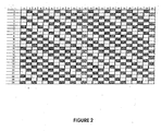
Pour des raisons de simplification de notation, la ligne Li,i+1 et la vanne Vi,i+1 sont ci-après et dans le tableau référencées par l'indice i.
Chaque ligne du tableau correspond à l'une des 24 étapes du cycle.
Chaque colonne du tableau indique la position de la vanne i (Vi,i+1) sur la ligne i (Li,i+1) au cours du cycle.
Les principes permettant d'établir ce tableau sont les suivants :
La ligne 2 du tableau est remplie en reportant la ligne 1 décalée d'une case vers la droite, et ainsi de suite.
Claims (10)
- Dispositif permettant de séparer au moins un composé recherché à partir d'un mélange comprenant ce composé, par adsorption en lit mobile simulé comportant :dans lequel lesdits moyens de mise en communication sont des dérivations Li,i+1 joignant deux lignes adjacentes Li et Li+1, qui sont externes à ladite vanne rotative multi-voies, ces dérivations Li,i+1 comprenant des moyens de sectionnement Vi,i+1, et étant de préférence situées à proximité de ladite vanne rotative multi-voies (RV).au moins une enceinte ou colonne, comportant une pluralité de lits d'adsorbants (Ai), deux lits d'adsorbants consécutifs étant séparés par au moins un plateau (Pi) de collecte/redistribution du fluide principal et d'injection/extraction de fluides secondaires de procédé, le plateau comportant un ou plusieurs panneaux de distribution/extraction/mélange, ou « DME », permettant de distribuer, extraire et/ou mélanger ces fluides,au moins une vanne rotative multi-voies (RV),une pluralité de conduits Li reliant ladite vanne rotative multi-voies auxdits plateaux Pi,pour une partie au moins des conduits Li, des moyens de mise en communication de deux conduits adjacents pour permettre la circulation de liquide de balayage à gradient de concentration faible ou nul pendant au moins 40% du temps,
- Dispositif selon la revendication 1 caractérisé en ce que lesdites dérivations Li,i+1 relient deux points sur les lignes Li et Li+1 qui sont respectivement dans le premier quart de la longueur de la ligne Li, respectivement Li+1, le plus proche de la vanne (RV).
- Dispositif selon l'une des revendications 1 et 2, comprenant des moyens de commande des moyens de sectionnement Vi,i+1, coordonnés avec la position de la vanne (RV) pour que Vi,i+1 soit en position ouverte lorsque ni Li ni Li+1 n'est parcouru par un fluide de procédé, sauf éventuellement lorsque Li ou Li+1 sont directement reliées à l'entrée (1) ou la sortie (2) de la colonne.
- Dispositif selon l'une des revendications 1 à 3, comprenant des moyens de balayage constitués par les lignes Li,j.
- Dispositif selon l'une des revendications 1 à 3, comprenant des moyens de balayage comprenant les lignes Li,j et des moyens internes à la vanne rotative (VR) de mise en circulation d'un fluide de balayage pendant une durée comprise entre 1 % et 15% du temps, entre deux lignes Li et Lj non adjacentes.
- Dispositif selon l'une des revendications 1 à 5, dans lequel les plateaux Pi comprennent des panneaux de distribution/extraction (DME) du type à secteurs parallèles à alimentations dissymétriques.
- Dispositif selon l'une des revendications 1 à 6, dans lequel les lits d'adsorbant Ai sont chargés en chargement dense.
- Dispositif selon l'une des revendications 1 à 5, dans lequel les plateaux Pi comprennent des des chambres Ci qui sont à la fois des chambres de distribution, de mélange, et d'extraction de fluides.
- Procédé de séparation d'un produit recherché à partir d'un mélange le comprenant, comprenant un dispositif selon l'une des revendications 1 à 8, dans lequel on réalise des balayages des lignes de dérivation Li,i+1 pendant au moins 50 % du temps.
- Procédé de séparation de paraxylene, ou de métaxylene, en tant que produit recherché, à partir d'une charge d'hydrocarbures aromatiques à 8 atomes de carbone, selon la revendication 9.
Applications Claiming Priority (2)
| Application Number | Priority Date | Filing Date | Title |
|---|---|---|---|
| FR0405645A FR2870751B1 (fr) | 2004-05-25 | 2004-05-25 | Procede et dispositif perfectionne de separation en lit mobile simule |
| FR0405645 | 2004-05-25 |
Publications (2)
| Publication Number | Publication Date |
|---|---|
| EP1600675A1 true EP1600675A1 (fr) | 2005-11-30 |
| EP1600675B1 EP1600675B1 (fr) | 2013-01-09 |
Family
ID=34942245
Family Applications (1)
| Application Number | Title | Priority Date | Filing Date |
|---|---|---|---|
| EP05290968A Expired - Lifetime EP1600675B1 (fr) | 2004-05-25 | 2005-05-02 | Procédé et dispositif perfectionné de séparation en lit mobile simulé |
Country Status (5)
| Country | Link |
|---|---|
| US (1) | US7473368B2 (fr) |
| EP (1) | EP1600675B1 (fr) |
| KR (1) | KR101164239B1 (fr) |
| CN (1) | CN100553741C (fr) |
| FR (1) | FR2870751B1 (fr) |
Families Citing this family (26)
| Publication number | Priority date | Publication date | Assignee | Title |
|---|---|---|---|---|
| FR2904776B1 (fr) * | 2006-08-08 | 2009-01-23 | Inst Francais Du Petrole | Procede et dispositif de separation en lit mobile simule a nombre de vannes reduit |
| FR2907021B1 (fr) * | 2006-10-16 | 2009-02-06 | Inst Francais Du Petrole | Procede et dispositif de separation en lit mobile simule a nombre de vannes de grand diametre reduit |
| FR2913345B1 (fr) * | 2007-03-09 | 2010-06-11 | Inst Francais Du Petrole | Procede et dispositif de separation en lit mobile simule a nombre de vannes et volume de lignes reduits |
| FR2913346B1 (fr) * | 2007-03-09 | 2009-04-24 | Inst Francais Du Petrole | Procede et dispositif de separation en lit mobile simule a nombre de vannes de grand diametre et volume de lignes reduits |
| FR2919604B1 (fr) * | 2007-07-30 | 2012-09-21 | Inst Francais Du Petrole | Procede et dispositif de separation ameliore de metaxylene en lit mobile simule |
| FR2919603B1 (fr) * | 2007-07-30 | 2012-09-21 | Inst Francais Du Petrole | Procede et dispositif de separation ameliore de paraxylene en lit mobile simule |
| FR2930454B1 (fr) * | 2008-04-25 | 2010-11-19 | Inst Francais Du Petrole | Systeme de distribution et de collecte des fluides dans une colonne multietagee |
| FR2935100B1 (fr) * | 2008-08-19 | 2011-03-18 | Inst Francais Du Petrole | Procede et dispositif de separation en lit mobile simule a debit de fluide de derivation module |
| KR101362490B1 (ko) * | 2008-11-19 | 2014-02-13 | 엑손모빌 케미칼 패턴츠 인코포레이티드 | 분리 방법 |
| FR2944215B1 (fr) * | 2009-04-10 | 2011-04-01 | Inst Francais Du Petrole | Procede et dispositif de separation en lit mobile simule comportant des lignes de derivation d'un lit sur deux et a debit de fluide de derivation module |
| JP5602224B2 (ja) * | 2009-05-29 | 2014-10-08 | エクソンモービル・ケミカル・パテンツ・インク | Parexユニット供給 |
| JP5709974B2 (ja) | 2010-03-30 | 2015-04-30 | エクソンモービル・ケミカル・パテンツ・インク | 分離システム |
| US8329975B2 (en) * | 2010-12-20 | 2012-12-11 | Uop Llc | Elimination of residual transfer line raffinate from feed to increase normal paraffin separation unit capacity |
| US8884092B2 (en) * | 2011-12-19 | 2014-11-11 | Uop Llc | Simulated moving bed systems for separation of para-xylene and processes for determining pump-around profiles of the simulated moving bed systems |
| US8349175B1 (en) | 2012-03-23 | 2013-01-08 | Orochem Technologies, Inc. | Rotary valve apparatus for simulated moving bed separations |
| US20140170763A1 (en) * | 2012-12-14 | 2014-06-19 | Uop Llc | Processes for Determining Stream Compositions in Simulated Moving Bed Systems |
| US9162205B2 (en) | 2012-12-31 | 2015-10-20 | Uop Llc | Apparatuses for distributing fluids in fluidized bed reactors |
| US9328041B2 (en) | 2013-09-24 | 2016-05-03 | Uop Llc | Methods and systems for separating para-xylene using a radial flow simulated moving bed chamber |
| US9090523B1 (en) | 2014-03-03 | 2015-07-28 | Uop Llc | Process for flushing top and bottom heads of a vessel |
| US9522862B2 (en) * | 2014-06-30 | 2016-12-20 | Uop Llc | Simulated moving bed separators and methods for isolating a desired component |
| CN106310712B (zh) * | 2015-06-30 | 2018-06-15 | 中国石油化工股份有限公司 | 一种降低吸附分离装置吸附塔与旋转阀间床层管线残余液体影响的方法 |
| FR3072885B1 (fr) | 2017-10-27 | 2019-11-15 | IFP Energies Nouvelles | Nouveau systeme de distribution par panneaux meridiens pour un procede de separation en lit mobile simule utilisant n-colonnes en serie |
| FR3095351B1 (fr) | 2019-04-25 | 2022-06-24 | Ifp Energies Now | Dispositif de distribution par panneaux méridiens avec séparation des réseaux de collecte |
| CN110465114B (zh) * | 2019-08-23 | 2021-08-20 | 内蒙古金达威药业有限公司 | 一种模拟移动床连续层析色谱系统及其应用以及纯化辅酶q10的方法 |
| CN111197123A (zh) * | 2020-01-15 | 2020-05-26 | 西安蓝晓科技新材料股份有限公司 | 一种锂钠分离的新方法 |
| CN114534447B (zh) * | 2022-03-16 | 2023-08-25 | 浙江天采云集科技股份有限公司 | 一种工业级乙醇全温程模拟旋转移动床变压吸附精制无水乙醇的方法 |
Citations (3)
| Publication number | Priority date | Publication date | Assignee | Title |
|---|---|---|---|---|
| EP0923970A1 (fr) * | 1997-12-22 | 1999-06-23 | Institut Francais Du Petrole | Procédé et dispositif d'amélioration de la pureté d'un produit en lit mobile simulé |
| FR2777798A1 (fr) * | 1998-04-27 | 1999-10-29 | Inst Francais Du Petrole | Procede et dispositif d'amelioration de la purete d'un produit en lit mobile simule comprenant une recirculation forcee de fluide |
| WO2000074807A1 (fr) * | 1999-06-09 | 2000-12-14 | Institut Francais Du Petrole | Systeme d'injection d'un fluide devie dans un procede de separation en lit mobile simule |
Family Cites Families (2)
| Publication number | Priority date | Publication date | Assignee | Title |
|---|---|---|---|---|
| US3268605A (en) | 1961-11-06 | 1966-08-23 | Universal Oil Prod Co | Supervisory control system for a simulated moving bed separation process |
| PL203219B1 (pl) | 2000-11-16 | 2009-09-30 | Uop Llc | Sposób wydzielania para-ksylenu metodą adsorbcyjną |
-
2004
- 2004-05-25 FR FR0405645A patent/FR2870751B1/fr not_active Expired - Fee Related
-
2005
- 2005-05-02 EP EP05290968A patent/EP1600675B1/fr not_active Expired - Lifetime
- 2005-05-24 KR KR1020050043669A patent/KR101164239B1/ko not_active Expired - Fee Related
- 2005-05-25 US US11/136,729 patent/US7473368B2/en not_active Expired - Fee Related
- 2005-05-25 CN CNB2005100743414A patent/CN100553741C/zh not_active Expired - Fee Related
Patent Citations (4)
| Publication number | Priority date | Publication date | Assignee | Title |
|---|---|---|---|---|
| EP0923970A1 (fr) * | 1997-12-22 | 1999-06-23 | Institut Francais Du Petrole | Procédé et dispositif d'amélioration de la pureté d'un produit en lit mobile simulé |
| US6110364A (en) * | 1997-12-22 | 2000-08-29 | Institut Francais Du Petrole | Device for improving the purity of a product in a simulated fluid bed |
| FR2777798A1 (fr) * | 1998-04-27 | 1999-10-29 | Inst Francais Du Petrole | Procede et dispositif d'amelioration de la purete d'un produit en lit mobile simule comprenant une recirculation forcee de fluide |
| WO2000074807A1 (fr) * | 1999-06-09 | 2000-12-14 | Institut Francais Du Petrole | Systeme d'injection d'un fluide devie dans un procede de separation en lit mobile simule |
Also Published As
| Publication number | Publication date |
|---|---|
| FR2870751A1 (fr) | 2005-12-02 |
| US20050269268A1 (en) | 2005-12-08 |
| KR20060048077A (ko) | 2006-05-18 |
| CN100553741C (zh) | 2009-10-28 |
| EP1600675B1 (fr) | 2013-01-09 |
| US7473368B2 (en) | 2009-01-06 |
| CN1714915A (zh) | 2006-01-04 |
| FR2870751B1 (fr) | 2006-08-04 |
| KR101164239B1 (ko) | 2012-07-09 |
Similar Documents
| Publication | Publication Date | Title |
|---|---|---|
| EP1600675B1 (fr) | Procédé et dispositif perfectionné de séparation en lit mobile simulé | |
| EP1913988B1 (fr) | Procédé et dispositif de séparation en lit mobile simulé à nombre de vannes de grand diametre reduit | |
| FR2913345A1 (fr) | Procede et dispositif de separation en lit mobile simule a nombre de vannes et volume de lignes reduits | |
| EP0923970B1 (fr) | Procédé et dispositif d'amélioration de la pureté d'un produit en lit mobile simulé | |
| EP1325772B1 (fr) | Dispositif d'injection d'un fluide dévié dans un procédé de séparation en lit mobile simulé | |
| FR2904776A1 (fr) | Procede et dispositif de separation en lit mobile simule a nombre de vannes reduit | |
| FR2794836A1 (fr) | Vanne rotative amelioree | |
| FR2956037A1 (fr) | Procede et dispositif de separation en lit mobile simule comportant des lignes de derivation d'un lit sur deux avec debits de balayage controles lors des injections et des soutirages | |
| EP1102615B1 (fr) | Systeme d'injection d'un fluide devie dans un procede de separation en lit mobile simule | |
| FR2944215A1 (fr) | Procede et dispositif de separation en lit mobile simule comportant des lignes de derivation d'un lit sur deux et a debit de fluide de derivation module | |
| FR2935101A1 (fr) | Procede et dispostif de separation en lit mobile simule a debit de fluide de derivation non regule automatiquement | |
| WO2010020715A1 (fr) | Procédé et dispositif de séparation en lit mobile simulé à débit de fluide de dérivation modulé | |
| WO2009101282A1 (fr) | Dispositif perfectionne de separation en lit mobile simule | |
| EP1646437B1 (fr) | Procede et dispositif de separation des constituants d'une charge liquide par chromatographie liquide-liquide centrifuge | |
| WO2008122705A2 (fr) | Procede et dispositif de separation en lit mobile simule a nombre de vannes de grand diametre et volume de lignes reduits | |
| CA2272638C (fr) | Dispositif de regulation de debit d'au moins un fluide d'unites de separation par lit mobile simule | |
| EP0846483B1 (fr) | Dispositif de rinçage dans une unité d'adsorption en lit mobile simulé comprenant deux lignes de distribution de fluides et son utilisation | |
| FR2777798A1 (fr) | Procede et dispositif d'amelioration de la purete d'un produit en lit mobile simule comprenant une recirculation forcee de fluide | |
| FR2781860A1 (fr) | Systeme de mise en communication alternee d'au moins quatre fluides et son application dans un procede de separation en lit mobile simule | |
| EP3583988B1 (fr) | Procédé et dispositif de séparation en lit mobile simulé à nombre de lits réduit avec débit de fluide de dérivation | |
| EP3583989B1 (fr) | Procédé et dispositif de séparation en lit mobile simulé à débit de fluide de dérivation | |
| EP3958995B1 (fr) | Dispositif de distribution par panneaux méridiens avec séparation des réseaux de collecte | |
| FR2831075A1 (fr) | Extracteurs liquide-liquide montes en batterie |
Legal Events
| Date | Code | Title | Description |
|---|---|---|---|
| PUAI | Public reference made under article 153(3) epc to a published international application that has entered the european phase |
Free format text: ORIGINAL CODE: 0009012 |
|
| AK | Designated contracting states |
Kind code of ref document: A1 Designated state(s): AT BE BG CH CY CZ DE DK EE ES FI FR GB GR HU IE IS IT LI LT LU MC NL PL PT RO SE SI SK TR |
|
| AX | Request for extension of the european patent |
Extension state: AL BA HR LV MK YU |
|
| 17P | Request for examination filed |
Effective date: 20060530 |
|
| AKX | Designation fees paid |
Designated state(s): BE DE ES IT NL |
|
| GRAP | Despatch of communication of intention to grant a patent |
Free format text: ORIGINAL CODE: EPIDOSNIGR1 |
|
| GRAS | Grant fee paid |
Free format text: ORIGINAL CODE: EPIDOSNIGR3 |
|
| GRAA | (expected) grant |
Free format text: ORIGINAL CODE: 0009210 |
|
| AK | Designated contracting states |
Kind code of ref document: B1 Designated state(s): BE DE ES IT NL |
|
| REG | Reference to a national code |
Ref country code: DE Ref legal event code: R096 Ref document number: 602005037796 Country of ref document: DE Effective date: 20130314 |
|
| REG | Reference to a national code |
Ref country code: NL Ref legal event code: VDEP Effective date: 20130109 |
|
| PG25 | Lapsed in a contracting state [announced via postgrant information from national office to epo] |
Ref country code: ES Free format text: LAPSE BECAUSE OF FAILURE TO SUBMIT A TRANSLATION OF THE DESCRIPTION OR TO PAY THE FEE WITHIN THE PRESCRIBED TIME-LIMIT Effective date: 20130420 |
|
| PG25 | Lapsed in a contracting state [announced via postgrant information from national office to epo] |
Ref country code: NL Free format text: LAPSE BECAUSE OF FAILURE TO SUBMIT A TRANSLATION OF THE DESCRIPTION OR TO PAY THE FEE WITHIN THE PRESCRIBED TIME-LIMIT Effective date: 20130109 |
|
| PLBE | No opposition filed within time limit |
Free format text: ORIGINAL CODE: 0009261 |
|
| STAA | Information on the status of an ep patent application or granted ep patent |
Free format text: STATUS: NO OPPOSITION FILED WITHIN TIME LIMIT |
|
| BERE | Be: lapsed |
Owner name: INSTITUT FRANCAIS DU PETROLE Effective date: 20130531 |
|
| 26N | No opposition filed |
Effective date: 20131010 |
|
| PG25 | Lapsed in a contracting state [announced via postgrant information from national office to epo] |
Ref country code: DE Free format text: LAPSE BECAUSE OF NON-PAYMENT OF DUE FEES Effective date: 20131203 |
|
| REG | Reference to a national code |
Ref country code: DE Ref legal event code: R097 Ref document number: 602005037796 Country of ref document: DE Effective date: 20131010 |
|
| REG | Reference to a national code |
Ref country code: DE Ref legal event code: R119 Ref document number: 602005037796 Country of ref document: DE Effective date: 20131203 |
|
| PG25 | Lapsed in a contracting state [announced via postgrant information from national office to epo] |
Ref country code: BE Free format text: LAPSE BECAUSE OF NON-PAYMENT OF DUE FEES Effective date: 20130531 |
|
| PGFP | Annual fee paid to national office [announced via postgrant information from national office to epo] |
Ref country code: IT Payment date: 20180531 Year of fee payment: 14 |
|
| PG25 | Lapsed in a contracting state [announced via postgrant information from national office to epo] |
Ref country code: IT Free format text: LAPSE BECAUSE OF NON-PAYMENT OF DUE FEES Effective date: 20190502 |