EP1600364B1 - Sattelanhänger - Google Patents
Sattelanhänger Download PDFInfo
- Publication number
- EP1600364B1 EP1600364B1 EP05450081A EP05450081A EP1600364B1 EP 1600364 B1 EP1600364 B1 EP 1600364B1 EP 05450081 A EP05450081 A EP 05450081A EP 05450081 A EP05450081 A EP 05450081A EP 1600364 B1 EP1600364 B1 EP 1600364B1
- Authority
- EP
- European Patent Office
- Prior art keywords
- slide plate
- plate
- frame
- sliding plate
- kingpin
- Prior art date
- Legal status (The legal status is an assumption and is not a legal conclusion. Google has not performed a legal analysis and makes no representation as to the accuracy of the status listed.)
- Expired - Lifetime
Links
- 230000008878 coupling Effects 0.000 description 5
- 238000010168 coupling process Methods 0.000 description 5
- 238000005859 coupling reaction Methods 0.000 description 5
- 238000007493 shaping process Methods 0.000 description 2
- 238000000465 moulding Methods 0.000 description 1
- 230000000284 resting effect Effects 0.000 description 1
Images

Classifications
-
- B—PERFORMING OPERATIONS; TRANSPORTING
- B62—LAND VEHICLES FOR TRAVELLING OTHERWISE THAN ON RAILS
- B62D—MOTOR VEHICLES; TRAILERS
- B62D53/00—Tractor-trailer combinations; Road trains
- B62D53/04—Tractor-trailer combinations; Road trains comprising a vehicle carrying an essential part of the other vehicle's load by having supporting means for the front or rear part of the other vehicle
- B62D53/08—Fifth wheel traction couplings
- B62D53/0842—King pins
Definitions
- the invention relates to a semi-trailer with a tether attached to side members of a chassis, comprising a frame frame with a king pin bearing sliding plate.
- a similar semi-trailer is eg: in DE 20 306 057 U disclosed.
- the tractor-trailer vehicle has a fifth-wheel coupling with a coupling plate on which the semi-trailer is supported via a trailer-mounted device.
- the trailer device of the semitrailer is understood to mean a sliding plate resting on the coupling plate of the fifth wheel, which carries a kingpin which can be locked in the fifth wheel. While the tensile forces to be transmitted between the semitrailer tractor and the semitrailer are absorbed by the kingpin, the vertical bearing forces are transmitted to the coupling plate via the sliding plate. This means that thennenliege adopted must accommodate both the support forces and the tensile forces.
- the bogie has a correspondingly stiffened frame frame, which is connected to the longitudinal members of the chassis of the semitrailer and carries on the underside of the sliding plate with the kingpin. Since the maximum height of a trailer is prescribed, the available cargo space height is determined in a semitrailer at a given height of the coupling plate of the fifth wheel by the height of the Aufliege worn. In order to use the largest possible hold height, it is known ( EP 0 439 409 B1 ), the kingpin is not on the underside of the sliding plate over a To screw flange, but to use from above through a passage opening in the sliding plate and to weld the opening edge of the top cross-mounting flange of the kingpin with the sliding plate. However, this measure brings only a limited reduction in the height of the trailer with him, because the height of the stiffened, load-bearing frame frame for reasons of strength can not be reduced below a minimum.
- the invention is therefore the object of a semi-trailer of the type described in such a way that a further reduction in the height of the trailer can be achieved.
- the invention solves this problem by the fact that the sliding plate is designed as a self-supporting, tethered to the longitudinal members of the chassis plate and that the frame frame, which has a maximum thickness of the sliding plate corresponding height adjoins the longitudinal end faces of the sliding plate.
- the slide plate is designed as a self-supporting, load-bearing connected to the side members of the chassis plate, an otherwise required stiffened frame frame for receiving the tension and traction forces omitted, so that the frame frame can be limited to adjoining the sliding plate bottom portions of the semitrailer in front of in particular, to absorb the weight load of the loading floor by the load.
- the thickness of the sliding plate determines the height of the Aufliege issued, because the height of the adjoining the sliding plate frame frame due to the limited load can be adapted to the thickness of the sliding plate without having to fear an overload.
- the sliding plate as a self-supporting, attached to the side members of the chassis plate brings in comparison to Aufliege issueden with a supporting frame frame a higher weight of the Aufliege issued with it, but this extra weight remains due to the possible restriction
- the plate size is limited to a level that can be taken into account in terms of gain in loading space height quite.
- the frame frame can be connected via molding tubes with a substantially rectangular cross-section of the sliding plate.
- the kingpin can be inserted into the sliding plate in a conventional manner from above through a passage opening, which can be formed discontinued due to the plate thickness, so that the kingpin bearing receiving plate is screwed onto the remote opening edge and does not project beyond the slide plate, yes forms a portion of the cargo bed. Due to the plate thickness but it is also possible to let the kingpin engage with its mounting flange in a recess on the underside of the sliding plate, without increasing the height of the Aufliege issued.
- sliding plate 3 overlaps the upper and lower chords 5, 6 of the trained in the tethering area as a box or I-beam side rail 4, the slide plate 3 on the top and bottom.
- the upper belts 5 comprise the sliding plate 3 in a plate recess to obtain a heelless loading surface defined by the surface of the sliding plate 3.
- the lower straps 6 of the longitudinal members 4, which have a greater grip length than the upper straps 5, are placed on the underside of the slide plate 3.
- the bottom of the semitrailer for example, from laid floorboards receiving rack frame 7 is attached to the longitudinal end faces of the slide plate 1, with the aid of mold tubes 8 having a substantially rectangular cross-section, as shown in FIG. 3 can be removed. Therefore, braking, control and power supply lines can be guided by the support device 1 through these shaping tubes 8. Since the sliding plate 3 takes over the Aufliege- and tensile forces, about the frame frame 7 only the ballast needs to be absorbed by the load of the semitrailer, which brings for the frame frame 7 comparatively low strength requirements. The frame frame 7 can therefore be carried out in a height corresponding to the thickness of the sliding plate 3, so that the thickness of the sliding plate 3 determines the height of the Aufliege observed easily.
- the kingpin 2 can be connected in different ways with the sliding plate 3.
- the king pin 2 is screwed via its mounting flange 12 from below to the sliding plate 3, which forms a recessed recess 13 for this purpose. Also in this embodiment, there is no increase in the height, because the mounting flange 12 comes to rest with the mounting screws within the recess 13 of the recess.
Landscapes
- Engineering & Computer Science (AREA)
- Chemical & Material Sciences (AREA)
- Combustion & Propulsion (AREA)
- Transportation (AREA)
- Mechanical Engineering (AREA)
- Vehicle Cleaning, Maintenance, Repair, Refitting, And Outriggers (AREA)
- Auxiliary Methods And Devices For Loading And Unloading (AREA)
- Control Of Throttle Valves Provided In The Intake System Or In The Exhaust System (AREA)
- Transition And Organic Metals Composition Catalysts For Addition Polymerization (AREA)
- Polysaccharides And Polysaccharide Derivatives (AREA)
- Handcart (AREA)
- Body Structure For Vehicles (AREA)
- Permanent Magnet Type Synchronous Machine (AREA)
- Glass Compositions (AREA)
Description
- Die Erfindung bezieht sich auf einen Sattelanhänger mit einer an Längsträger eines Fahrgestells angebundenen Aufliegeeinrichtung, die einen Gestellrahmen mit einer einen Königszapfen tragenden Gleitplatte umfaßt.
- Ein ähnlicher Sattelanhänger ist z.B.: in
DE 20 306 057 U offenbart. - Zur Verbindung eines Sattelzugfahrzeuges mit einem Sattelanhänger weist das Sattelzugfahrzeug eine Sattelkupplung mit einer Kupplungsplatte auf, auf der sich der Sattelanhänger über eine Aufliegeeinrichtung abstützt. Zu diesem Zweck ist die Aufliegeeinrichtung des Sattelanhängers mit einer auf der Kupplungsplatte der Sattelkupplung aufliegenden Gleitplatte verstehen, die einen in der Sattelkupplung verriegelbaren Königszapfen trägt. Während die zwischen dem Sattelzugfahrzeug und dem Sattelanhänger zu übertragenden Zugkräfte vom Königszapfen aufgenommen werden, werden die vertikalen Auflagekräfte über die Gleitplatte auf die Kupplungsplatte übertragen. Dies bedeutet, daß die Aufliegeeinrichtung sowohl die Aufliegekräfte als auch die Zugkräfte aufnehmen muß. Aus diesem Grunde weist die Aufliegeeinrichtung einen entsprechend ausgesteiften Gestellrahmen auf, der an den Längsträgern des Fahrgestells des Sattelanhängers angebunden ist und auf der Unterseite die Gleitplatte mit dem Königszapfen trägt. Da die maximale Höhe eines Anhängers vorgeschrieben ist, wird die zur Verfügung stehende Laderaumhöhe bei einem Sattelanhänger bei vorgegebener Höhe der Kupplungsplatte der Sattelkupplung durch die Bauhöhe der Aufliegeeinrichtung bestimmt. Um eine möglichst große Laderaumhöhe nutzen zu können, ist es bekannt (
EP 0 439 409 B1 ), den Königszapfen nicht an der Unterseite der Gleitplatte über einen Flansch anzuschrauben, sondern von oben durch eine Durchtrittsöffnung in die Gleitplatte einzusetzen und den den Öffnungsrand von oben übergreifenden Befestigungsflansch des Königszapfens mit der Gleitplatte zu verschweißen. Diese Maßnahme bringt jedoch nur eine begrenzte Erniedrigung der Bauhöhe der Aufliegeeinrichtung mit sich, weil die Höhe des ausgesteiften, lastabtragenden Gestellrahmens aus Festigkeitsgründen nicht unter ein Mindestmaß verringert kann. - Der Erfindung liegt somit die Aufgabe zugrunde, einen Sattelanhänger der eingangs geschilderten Art so auszugestalten, daß eine weitere Verringerung der Bauhöhe der Aufliegeeinrichtung erreicht werden kann.
- Die Erfindung löst die gestellte Aufgabe dadurch, daß die Gleitplatte als selbsttragende, an die Längsträger des Fahrgestells angebundene Platte ausgebildet ist und daß der Gestellrahmen, der eine höchstens der Dicke der Gleitplatte entsprechende Höhe aufweist, an den längsseitigen Stirnflächen der Gleitplatte anschließt.
- Da die Gleitplatte als selbsttragende, lastabtragend an die Längsträger des Fahrgestells angebundene Platte ausgebildet ist, kann ein sonst erforderlicher ausgesteifter Gestellrahmen zur Aufnahme der Aufliege- und Zugkräfte entfallen, so daß der Gestellrahmen auf an die Gleitplatte anschließende Bodenbereiche des Sattelanhängers beschränkt werden kann, um vor allem die Gewichtsbelastung des Ladebodens durch die Ladung aufzunehmen. Dies bedeutet, daß die Dicke der Gleitplatte die Bauhöhe der Aufliegeeinrichtung bestimmt, weil die Höhe des an die Gleitplatte anschließenden Gestellrahmens aufgrund der beschränkten Belastung durchaus an die Dicke der Gleitplatte angepaßt werden kann, ohne eine Überlastung befürchten zu müssen. Die Ausbildung der Gleitplatte als selbsttragende, an die Längsträger des Fahrgestells angebundene Platte bringt zwar im Vergleich zu Aufliegeeinrichtungen mit einem tragenden Gestellrahmen ein höheres Gewicht der Aufliegeeinrichtung mit sich, doch bleibt dieses Mehrgewicht aufgrund der möglichen Beschränkung der Plattengröße auf ein Maß begrenzt, das im Hinblick auf den Gewinn an Laderaumhöhe durchaus in Kauf genommen werden kann.
- Um die Brems-, Steuer- und Energieversorgungsleitungen für den Sattelanhänger trotz der die Bauhöhe bestimmenden, selbsttragenden Gleitplatte durch die Aufliegeeinrichtung in einfache Weise führen zu können, kann der Gestellrahmen über Formrohre mit einem im wesentlichen rechteckigen Querschnitt an die Gleitplatte angeschlossen sein. Durch diese in Längsrichtung der Aufliegeeinrichtung verlaufenden Formrohre können die jeweiligen Leitungen unbehindert verlegt werden.
- Der Königszapfen kann in die Gleitplatte in an sich bekannter Weise von oben durch eine Durchtrittsöffnung eingesetzt werden, die aufgrund der Plattendicke abgesetzt ausgebildet werden kann, so daß der den Königszapfen tragende Aufnahmeteller auf dem abgesetzten Öffnungsrand aufgeschraubt wird und nicht über die Gleitplatte vorsteht, die ja einen Abschnitt der Ladefläche bildet. Aufgrund der Plattendicke besteht aber auch die Möglichkeit, den Königszapfen mit seinem Befestigungsflansch in eine Ausnehmung auf der Unterseite der Gleitplatte eingreifen zu lassen, ohne die Bauhöhe der Aufliegeeinrichtung zu vergrößern.
- In der Zeichnung ist der Erfindungsgegenstand beispielsweise dargestellt. Es zeigen
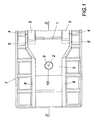
- Fig. 1
- die Aufliegeeinrichtung eines erfindungsgemäßen Sattelanhängers in einer vereinfachten Draufsicht,
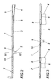
- Fig. 2
- einen Schnitt durch die Aufliegeeinrichtung nach der Linie II-II der Fig. 1 in einem größeren Maßstab,
- Fig. 3
- einen Schnitt durch die Aufliegeeinrichtung nach der Linie III-III der Fig. 2,
- Fig. 4
- einen Schnitt durch die Gleitplatte im Bereich des Königszapfens in einem größeren Maßstab und
- Fig. 5
- eine der Fig. 4 entsprechende Darstellung einer Konstruktionsvariante.
- Wie sich insbesondere aus den Fig. 1 bis 3 ergibt, weist die Aufliegeeinrichtung 1 eines nicht näher dargestellten Sattelanhängers eine einen Königszapfen 2 aufnehmende Gleitplatte 3 auf, die als selbsttragende Platte ausgebildet ist und als solche an die Längsträger 4 des Fahrgestells lastabtragend angebunden wird. Zu diesem Zweck übergreifen die Ober- und Untergurte 5, 6 der im Anbindebereich als Kasten- oder I-Träger ausgebildeten Längsträger 4 die Gleitplatte 3 auf der Ober- und Unterseite. Wie der Fig. 2 entnommen werden kann, umfassen die Obergurte 5 die Gleitplatte 3 in einer Plattenvertiefung, um eine absatzlose, durch die Oberfläche der Gleitplatte 3 bestimmte Ladefläche zu erhalten. Die Untergurte 6 der Längsträger 4, die eine größere Übergriffslänge als die Obergurte 5 aufweisen, sind auf der Unterseite der Gleitplatte 3 aufgesetzt. Der den beispielsweise aus verlegten Dielen gefügten Boden des Sattelanhängers aufnehmende Gestellrahmen 7 ist an den längsseitigen Stirnflächen der Gleitplatte 1 angesetzt, und zwar mit Hilfe von Formrohren 8 mit einem im wesentlichen rechteckigen Querschnitt, wie dies der Fig. 3 entnommen werden kann. Durch diese Formrohre 8 können daher Brems-, Steuer- und Energieversorgungsleitungen durch die Aufliegeeinrichtung 1 geführt werden. Da die Gleitplatte 3 die Aufliege- und Zugkräfte übernimmt, braucht über den Gestellrahmen 7 lediglich die Auflast durch die Ladung des Sattelanhängers aufgenommen zu werden, was für den Gestellrahmen 7 vergleichsweise geringe Festigkeitsanforderungen mit sich bringt. Der Gestellrahmen 7 kann daher ohne weiteres in einer der Dicke der Gleitplatte 3 entsprechenden Höhe ausgeführt werden, so daß die Dicke der Gleitplatte 3 die Bauhöhe der Aufliegeeinrichtung bestimmt.
- Der Königszapfen 2 kann in unterschiedlicher Weise mit der Gleitplatte 3 verbunden werden. So ist es gemäß der Fig. 4 möglich, den Königszapfen in einen Aufnahmeteller 9 einzusetzen, der von oben in eine abgesetzte Durchtrittsöffnung 10 der Gleitplatte 3 eingreift und auf dem abgesetzten Öffnungsrand 11 befestigt wird. Aufgrund der aus Festigkeitsgründen notwendigen Dicke der Gleitplatte 3 ist der Aufnahmeteller 9 in der abgesetzten Durchtrittsöffnung 10 versenkt angeordnet und ragt daher nicht über die durch die Oberfläche der Gleitplatte 3 bestimmte Ladefläche vor.
- Gemäß der Fig. 5 wird der Königszapfen 2 über seinen Befestigungsflansch 12 von unten an der Gleitplatte 3 angeschraubt, die zu diesem Zweck eine vertiefte Ausnehmung 13 bildet. Auch bei dieser Ausführungsform ergibt sich keine Vergrößerung der Bauhöhe, weil der Befestigungsflansch 12 mit den Befestigungsschrauben innerhalb der Vertiefung der Ausnehmung 13 zu liegen kommt.
Claims (4)
- Sattelanhänger mit einer an Längsträger (4) eines Fahrgestells angebundenen Aufliegeeinrichtung (1), die einen Gestellrahmen (7) mit einer einen Königszapfen (2) tragenden Gleitplatte (3) umfaßt, dadurch gekennzeichnet, daß die Gleitplatte (3) als selbsttragende, an die Längsträger (4) des Fahrgestells angebundene Platte ausgebildet ist und daß der Gestellrahmen (7), der eine höchstens der Dicke der Gleitplatte (3) entsprechende Höhe aufweist, an den längsseitigen Stirnflächen der Gleitplatte (3) anschließt.
- Sattelanhänger nach Anspruch 1, dadurch gekennzeichnet, daß der Gestellrahmen (7) über Formrohre (8) mit einem im wesentlichen rechteckigen Querschnitt an die Gleitplatte (3) angeschlossen ist.
- Sattelanhänger nach Anspruch 1 oder 2, dadurch gekennzeichnet, daß der in einem Aufnahmeteller (9) gehaltene Königszapfen (2) von oben in eine abgesetzte Durchtrittsöffnung (10) der Gleitplatte (3) eingesetzt ist.
- Sattelanhänger nach Anspruch 1 oder 2, dadurch gekennzeichnet, daß der Königszapfen (2) mit seinem Befestigungsflansch (12) in eine Ausnehmung (13) auf der Unterseite der Gleitplatte (3) eingreift.
Priority Applications (1)
| Application Number | Priority Date | Filing Date | Title |
|---|---|---|---|
| SI200530208T SI1600364T1 (sl) | 2004-05-26 | 2005-05-02 | Polprikolica |
Applications Claiming Priority (2)
| Application Number | Priority Date | Filing Date | Title |
|---|---|---|---|
| AT0090704A AT413522B (de) | 2004-05-26 | 2004-05-26 | Sattelanhänger |
| AT9072004 | 2004-05-26 |
Publications (3)
| Publication Number | Publication Date |
|---|---|
| EP1600364A2 EP1600364A2 (de) | 2005-11-30 |
| EP1600364A3 EP1600364A3 (de) | 2006-12-27 |
| EP1600364B1 true EP1600364B1 (de) | 2008-01-09 |
Family
ID=34842281
Family Applications (1)
| Application Number | Title | Priority Date | Filing Date |
|---|---|---|---|
| EP05450081A Expired - Lifetime EP1600364B1 (de) | 2004-05-26 | 2005-05-02 | Sattelanhänger |
Country Status (4)
| Country | Link |
|---|---|
| EP (1) | EP1600364B1 (de) |
| AT (2) | AT413522B (de) |
| DE (1) | DE502005002461D1 (de) |
| SI (1) | SI1600364T1 (de) |
Families Citing this family (1)
| Publication number | Priority date | Publication date | Assignee | Title |
|---|---|---|---|---|
| FR2967614B1 (fr) * | 2010-11-18 | 2015-01-23 | Marc Marcel Ellegeest | Attelage automatique rotatif a bague |
Family Cites Families (3)
| Publication number | Priority date | Publication date | Assignee | Title |
|---|---|---|---|---|
| FR2657320B1 (fr) * | 1990-01-25 | 1992-09-11 | Europ Semi Remorques | Plateau de remorque ou de semi-remorque muni d'une structure d'attelage de faible epaisseur. |
| DE9110124U1 (de) * | 1991-08-16 | 1991-09-26 | Maschinenfabriken Bernard Krone Gmbh, 4441 Spelle | Sattelanhänger |
| DE20306057U1 (de) * | 2003-03-20 | 2003-07-24 | Cramer Kupplung GmbH & Co. KG, 45356 Essen | Aufliegervorrichtung für einen Sattelanhänger |
-
2004
- 2004-05-26 AT AT0090704A patent/AT413522B/de not_active IP Right Cessation
-
2005
- 2005-05-02 AT AT05450081T patent/ATE383299T1/de active
- 2005-05-02 SI SI200530208T patent/SI1600364T1/sl unknown
- 2005-05-02 DE DE502005002461T patent/DE502005002461D1/de not_active Expired - Lifetime
- 2005-05-02 EP EP05450081A patent/EP1600364B1/de not_active Expired - Lifetime
Also Published As
| Publication number | Publication date |
|---|---|
| EP1600364A3 (de) | 2006-12-27 |
| AT413522B (de) | 2006-03-15 |
| ATA9072004A (de) | 2005-08-15 |
| ATE383299T1 (de) | 2008-01-15 |
| EP1600364A2 (de) | 2005-11-30 |
| DE502005002461D1 (de) | 2008-02-21 |
| SI1600364T1 (sl) | 2008-06-30 |
Similar Documents
| Publication | Publication Date | Title |
|---|---|---|
| DE4316930C2 (de) | Sitzbank für Kraftfahrzeuge, insbesondere Wohnmobile | |
| DE102005044907B4 (de) | Heckseitige Fahrzeugkarosseriestruktur eines Kraftfahrzeugs | |
| DE69704882T2 (de) | Selbsttragender Kühlwagen | |
| DE69317993T2 (de) | Eingebaute Wägevorrichtung in einem Fahrzeug, wie ein Lastkraftwagen oder ein ähnliches Fahrzeug | |
| DE602006000206T2 (de) | Bewegbare Wanne für den Transport von einem Sattelauflieger, mit einer solchen Wanne ausgerüsteter Waggon und Ladenverfahren des Sattelaufliegers | |
| EP1600364B1 (de) | Sattelanhänger | |
| DE9304926U1 (de) | Fahrgestell für Fahrzeuganhänger | |
| WO2012022789A1 (de) | Lageranordnung einer sattelkupplung | |
| DE68915877T2 (de) | Strasseneinheit mit absetzbarer Trägerkarosserie. | |
| DE69408124T2 (de) | Fahrgestell für einen autobus | |
| DE3523742C2 (de) | ||
| EP0065623A1 (de) | Flanschkonstruktion für die Schraubverbindung zwischen einem Anhänger-Fahrgestell und dem Rahmen des Anhänger-Aufbaues | |
| DE102017100847A1 (de) | Trägerstruktur für ein nicht-angetriebenes Nutzfahrzeug | |
| EP0379909A2 (de) | Nutzfahrzeug mit reversierbarem Ladeboden | |
| DE10045169B4 (de) | Sattelauflieger-Fahrzeug zum Transport von Lang-oder Kurzmaterial | |
| EP0982160B1 (de) | Fahrzeugchassis mit Aufprallschutz für Fahrzeuge | |
| DE4212161A1 (de) | Sattelauflieger | |
| DE19843396C1 (de) | Bodengruppe für einen Fahrzeuganhänger, vorzugsweise einen Wohnanhänger | |
| DE4328623C2 (de) | Sattelanhänger | |
| EP1679252A1 (de) | Karosserieverbindungsanordnung | |
| EP0538893B1 (de) | Sattelzugfahrzeug | |
| DE3400878A1 (de) | Lastkraftfahrzeug mit kuppelbarem einachsanhaenger | |
| DE29711061U1 (de) | Fahrgestell für einen Kraftfahrzeuganhänger | |
| DE8901811U1 (de) | Haltevorrichtung für eine Anhänger-Kupplung | |
| DE29618927U1 (de) | Zwischenrahmen-Vorrichtung für Anhänger oder Sattelauflieger |
Legal Events
| Date | Code | Title | Description |
|---|---|---|---|
| PUAI | Public reference made under article 153(3) epc to a published international application that has entered the european phase |
Free format text: ORIGINAL CODE: 0009012 |
|
| AK | Designated contracting states |
Kind code of ref document: A2 Designated state(s): AT BE BG CH CY CZ DE DK EE ES FI FR GB GR HU IE IS IT LI LT LU MC NL PL PT RO SE SI SK TR |
|
| AX | Request for extension of the european patent |
Extension state: AL BA HR LV MK YU |
|
| PUAL | Search report despatched |
Free format text: ORIGINAL CODE: 0009013 |
|
| AK | Designated contracting states |
Kind code of ref document: A3 Designated state(s): AT BE BG CH CY CZ DE DK EE ES FI FR GB GR HU IE IS IT LI LT LU MC NL PL PT RO SE SI SK TR |
|
| AX | Request for extension of the european patent |
Extension state: AL BA HR LV MK YU |
|
| 17P | Request for examination filed |
Effective date: 20070226 |
|
| AKX | Designation fees paid |
Designated state(s): AT BE BG CH CY CZ DE DK EE ES FI FR GB GR HU IE IS IT LI LT LU MC NL PL PT RO SE SI SK TR |
|
| GRAP | Despatch of communication of intention to grant a patent |
Free format text: ORIGINAL CODE: EPIDOSNIGR1 |
|
| GRAS | Grant fee paid |
Free format text: ORIGINAL CODE: EPIDOSNIGR3 |
|
| GRAA | (expected) grant |
Free format text: ORIGINAL CODE: 0009210 |
|
| AK | Designated contracting states |
Kind code of ref document: B1 Designated state(s): AT BE BG CH CY CZ DE DK EE ES FI FR GB GR HU IE IS IT LI LT LU MC NL PL PT RO SE SI SK TR |
|
| REG | Reference to a national code |
Ref country code: GB Ref legal event code: FG4D Free format text: NOT ENGLISH |
|
| REG | Reference to a national code |
Ref country code: CH Ref legal event code: EP |
|
| REG | Reference to a national code |
Ref country code: IE Ref legal event code: FG4D Free format text: LANGUAGE OF EP DOCUMENT: GERMAN |
|
| REF | Corresponds to: |
Ref document number: 502005002461 Country of ref document: DE Date of ref document: 20080221 Kind code of ref document: P |
|
| REG | Reference to a national code |
Ref country code: RO Ref legal event code: EPE |
|
| REG | Reference to a national code |
Ref country code: CH Ref legal event code: PCAR Free format text: PATENTANWALTSBUREAU STEUDTNER;AHORNWEG 12;5702 NIEDERLENZ (CH) Ref country code: CH Ref legal event code: NV Representative=s name: DIPL.-ING. W. STEUDTNER |
|
| PG25 | Lapsed in a contracting state [announced via postgrant information from national office to epo] |
Ref country code: NL Free format text: LAPSE BECAUSE OF FAILURE TO SUBMIT A TRANSLATION OF THE DESCRIPTION OR TO PAY THE FEE WITHIN THE PRESCRIBED TIME-LIMIT Effective date: 20080109 |
|
| NLV1 | Nl: lapsed or annulled due to failure to fulfill the requirements of art. 29p and 29m of the patents act | ||
| PG25 | Lapsed in a contracting state [announced via postgrant information from national office to epo] |
Ref country code: LT Free format text: LAPSE BECAUSE OF FAILURE TO SUBMIT A TRANSLATION OF THE DESCRIPTION OR TO PAY THE FEE WITHIN THE PRESCRIBED TIME-LIMIT Effective date: 20080109 Ref country code: IS Free format text: LAPSE BECAUSE OF FAILURE TO SUBMIT A TRANSLATION OF THE DESCRIPTION OR TO PAY THE FEE WITHIN THE PRESCRIBED TIME-LIMIT Effective date: 20080509 Ref country code: FI Free format text: LAPSE BECAUSE OF FAILURE TO SUBMIT A TRANSLATION OF THE DESCRIPTION OR TO PAY THE FEE WITHIN THE PRESCRIBED TIME-LIMIT Effective date: 20080109 Ref country code: ES Free format text: LAPSE BECAUSE OF FAILURE TO SUBMIT A TRANSLATION OF THE DESCRIPTION OR TO PAY THE FEE WITHIN THE PRESCRIBED TIME-LIMIT Effective date: 20080420 |
|
| GBV | Gb: ep patent (uk) treated as always having been void in accordance with gb section 77(7)/1977 [no translation filed] | ||
| REG | Reference to a national code |
Ref country code: HU Ref legal event code: AG4A Ref document number: E003160 Country of ref document: HU |
|
| PG25 | Lapsed in a contracting state [announced via postgrant information from national office to epo] |
Ref country code: BG Free format text: LAPSE BECAUSE OF FAILURE TO SUBMIT A TRANSLATION OF THE DESCRIPTION OR TO PAY THE FEE WITHIN THE PRESCRIBED TIME-LIMIT Effective date: 20080409 |
|
| ET | Fr: translation filed | ||
| PG25 | Lapsed in a contracting state [announced via postgrant information from national office to epo] |
Ref country code: PL Free format text: LAPSE BECAUSE OF FAILURE TO SUBMIT A TRANSLATION OF THE DESCRIPTION OR TO PAY THE FEE WITHIN THE PRESCRIBED TIME-LIMIT Effective date: 20080109 Ref country code: PT Free format text: LAPSE BECAUSE OF FAILURE TO SUBMIT A TRANSLATION OF THE DESCRIPTION OR TO PAY THE FEE WITHIN THE PRESCRIBED TIME-LIMIT Effective date: 20080609 |
|
| REG | Reference to a national code |
Ref country code: IE Ref legal event code: FD4D |
|
| PG25 | Lapsed in a contracting state [announced via postgrant information from national office to epo] |
Ref country code: IE Free format text: LAPSE BECAUSE OF FAILURE TO SUBMIT A TRANSLATION OF THE DESCRIPTION OR TO PAY THE FEE WITHIN THE PRESCRIBED TIME-LIMIT Effective date: 20080109 Ref country code: DK Free format text: LAPSE BECAUSE OF FAILURE TO SUBMIT A TRANSLATION OF THE DESCRIPTION OR TO PAY THE FEE WITHIN THE PRESCRIBED TIME-LIMIT Effective date: 20080109 Ref country code: SE Free format text: LAPSE BECAUSE OF FAILURE TO SUBMIT A TRANSLATION OF THE DESCRIPTION OR TO PAY THE FEE WITHIN THE PRESCRIBED TIME-LIMIT Effective date: 20080409 |
|
| PLBE | No opposition filed within time limit |
Free format text: ORIGINAL CODE: 0009261 |
|
| STAA | Information on the status of an ep patent application or granted ep patent |
Free format text: STATUS: NO OPPOSITION FILED WITHIN TIME LIMIT |
|
| BERE | Be: lapsed |
Owner name: WILHELM SCHWARZMULLER -G. M.B.H. Effective date: 20080531 |
|
| 26N | No opposition filed |
Effective date: 20081010 |
|
| PG25 | Lapsed in a contracting state [announced via postgrant information from national office to epo] |
Ref country code: MC Free format text: LAPSE BECAUSE OF NON-PAYMENT OF DUE FEES Effective date: 20080531 Ref country code: GB Free format text: LAPSE BECAUSE OF FAILURE TO SUBMIT A TRANSLATION OF THE DESCRIPTION OR TO PAY THE FEE WITHIN THE PRESCRIBED TIME-LIMIT Effective date: 20080109 |
|
| PG25 | Lapsed in a contracting state [announced via postgrant information from national office to epo] |
Ref country code: EE Free format text: LAPSE BECAUSE OF FAILURE TO SUBMIT A TRANSLATION OF THE DESCRIPTION OR TO PAY THE FEE WITHIN THE PRESCRIBED TIME-LIMIT Effective date: 20080109 |
|
| PG25 | Lapsed in a contracting state [announced via postgrant information from national office to epo] |
Ref country code: BE Free format text: LAPSE BECAUSE OF NON-PAYMENT OF DUE FEES Effective date: 20080531 |
|
| PG25 | Lapsed in a contracting state [announced via postgrant information from national office to epo] |
Ref country code: CY Free format text: LAPSE BECAUSE OF FAILURE TO SUBMIT A TRANSLATION OF THE DESCRIPTION OR TO PAY THE FEE WITHIN THE PRESCRIBED TIME-LIMIT Effective date: 20080109 |
|
| PG25 | Lapsed in a contracting state [announced via postgrant information from national office to epo] |
Ref country code: LU Free format text: LAPSE BECAUSE OF NON-PAYMENT OF DUE FEES Effective date: 20080502 |
|
| PGFP | Annual fee paid to national office [announced via postgrant information from national office to epo] |
Ref country code: FR Payment date: 20100609 Year of fee payment: 6 Ref country code: HU Payment date: 20100409 Year of fee payment: 6 Ref country code: RO Payment date: 20100426 Year of fee payment: 6 |
|
| PG25 | Lapsed in a contracting state [announced via postgrant information from national office to epo] |
Ref country code: TR Free format text: LAPSE BECAUSE OF FAILURE TO SUBMIT A TRANSLATION OF THE DESCRIPTION OR TO PAY THE FEE WITHIN THE PRESCRIBED TIME-LIMIT Effective date: 20080109 |
|
| PGFP | Annual fee paid to national office [announced via postgrant information from national office to epo] |
Ref country code: CZ Payment date: 20100310 Year of fee payment: 6 Ref country code: IT Payment date: 20100527 Year of fee payment: 6 Ref country code: SI Payment date: 20100407 Year of fee payment: 6 Ref country code: SK Payment date: 20100423 Year of fee payment: 6 |
|
| PG25 | Lapsed in a contracting state [announced via postgrant information from national office to epo] |
Ref country code: GR Free format text: LAPSE BECAUSE OF FAILURE TO SUBMIT A TRANSLATION OF THE DESCRIPTION OR TO PAY THE FEE WITHIN THE PRESCRIBED TIME-LIMIT Effective date: 20080410 |
|
| PGFP | Annual fee paid to national office [announced via postgrant information from national office to epo] |
Ref country code: CH Payment date: 20100604 Year of fee payment: 6 |
|
| REG | Reference to a national code |
Ref country code: CH Ref legal event code: PCAR Free format text: PATENTANWALTSBUERO STEUDTNER;AHORNWEG 6;5702 NIEDERLENZ (CH) |
|
| REG | Reference to a national code |
Ref country code: CH Ref legal event code: PL |
|
| PG25 | Lapsed in a contracting state [announced via postgrant information from national office to epo] |
Ref country code: CZ Free format text: LAPSE BECAUSE OF NON-PAYMENT OF DUE FEES Effective date: 20110502 Ref country code: HU Free format text: LAPSE BECAUSE OF NON-PAYMENT OF DUE FEES Effective date: 20110503 Ref country code: LI Free format text: LAPSE BECAUSE OF NON-PAYMENT OF DUE FEES Effective date: 20110531 Ref country code: CH Free format text: LAPSE BECAUSE OF NON-PAYMENT OF DUE FEES Effective date: 20110531 |
|
| REG | Reference to a national code |
Ref country code: SI Ref legal event code: KO00 Effective date: 20111206 |
|
| REG | Reference to a national code |
Ref country code: SK Ref legal event code: MM4A Ref document number: E 3394 Country of ref document: SK Effective date: 20110502 |
|
| REG | Reference to a national code |
Ref country code: FR Ref legal event code: ST Effective date: 20120131 |
|
| PG25 | Lapsed in a contracting state [announced via postgrant information from national office to epo] |
Ref country code: IT Free format text: LAPSE BECAUSE OF NON-PAYMENT OF DUE FEES Effective date: 20110502 Ref country code: SI Free format text: LAPSE BECAUSE OF NON-PAYMENT OF DUE FEES Effective date: 20110503 Ref country code: SK Free format text: LAPSE BECAUSE OF NON-PAYMENT OF DUE FEES Effective date: 20110502 |
|
| PG25 | Lapsed in a contracting state [announced via postgrant information from national office to epo] |
Ref country code: FR Free format text: LAPSE BECAUSE OF NON-PAYMENT OF DUE FEES Effective date: 20110531 |
|
| PG25 | Lapsed in a contracting state [announced via postgrant information from national office to epo] |
Ref country code: RO Free format text: LAPSE BECAUSE OF NON-PAYMENT OF DUE FEES Effective date: 20110502 |
|
| PGFP | Annual fee paid to national office [announced via postgrant information from national office to epo] |
Ref country code: AT Payment date: 20120504 Year of fee payment: 8 |
|
| PGFP | Annual fee paid to national office [announced via postgrant information from national office to epo] |
Ref country code: DE Payment date: 20130411 Year of fee payment: 9 |
|
| REG | Reference to a national code |
Ref country code: DE Ref legal event code: R119 Ref document number: 502005002461 Country of ref document: DE |
|
| REG | Reference to a national code |
Ref country code: AT Ref legal event code: MM01 Ref document number: 383299 Country of ref document: AT Kind code of ref document: T Effective date: 20140502 |
|
| REG | Reference to a national code |
Ref country code: DE Ref legal event code: R119 Ref document number: 502005002461 Country of ref document: DE Effective date: 20141202 |
|
| PG25 | Lapsed in a contracting state [announced via postgrant information from national office to epo] |
Ref country code: AT Free format text: LAPSE BECAUSE OF NON-PAYMENT OF DUE FEES Effective date: 20140502 |
|
| PG25 | Lapsed in a contracting state [announced via postgrant information from national office to epo] |
Ref country code: DE Free format text: LAPSE BECAUSE OF NON-PAYMENT OF DUE FEES Effective date: 20141202 |