EP1599683B1 - Mehrstrangschraubenfeder - Google Patents
Mehrstrangschraubenfeder Download PDFInfo
- Publication number
- EP1599683B1 EP1599683B1 EP04712878.0A EP04712878A EP1599683B1 EP 1599683 B1 EP1599683 B1 EP 1599683B1 EP 04712878 A EP04712878 A EP 04712878A EP 1599683 B1 EP1599683 B1 EP 1599683B1
- Authority
- EP
- European Patent Office
- Prior art keywords
- spring
- coil
- strand
- strands
- springs
- Prior art date
- Legal status (The legal status is an assumption and is not a legal conclusion. Google has not performed a legal analysis and makes no representation as to the accuracy of the status listed.)
- Expired - Lifetime
Links
- 239000000463 material Substances 0.000 claims description 23
- 230000002009 allergenic effect Effects 0.000 claims description 2
- 230000000712 assembly Effects 0.000 claims description 2
- 238000000429 assembly Methods 0.000 claims description 2
- 239000011248 coating agent Substances 0.000 claims description 2
- 238000000576 coating method Methods 0.000 claims description 2
- 238000010276 construction Methods 0.000 description 25
- 239000006260 foam Substances 0.000 description 14
- 229910000831 Steel Inorganic materials 0.000 description 10
- 239000007787 solid Substances 0.000 description 10
- 239000010959 steel Substances 0.000 description 10
- 239000004033 plastic Substances 0.000 description 8
- 229920003023 plastic Polymers 0.000 description 8
- 229920001971 elastomer Polymers 0.000 description 6
- 230000000284 resting effect Effects 0.000 description 6
- 239000005060 rubber Substances 0.000 description 6
- 238000004519 manufacturing process Methods 0.000 description 5
- 230000004044 response Effects 0.000 description 5
- 239000004593 Epoxy Substances 0.000 description 4
- 239000002131 composite material Substances 0.000 description 4
- 238000000034 method Methods 0.000 description 4
- RTAQQCXQSZGOHL-UHFFFAOYSA-N Titanium Chemical compound [Ti] RTAQQCXQSZGOHL-UHFFFAOYSA-N 0.000 description 3
- 239000004744 fabric Substances 0.000 description 3
- 239000010936 titanium Substances 0.000 description 3
- 229910052719 titanium Inorganic materials 0.000 description 3
- 238000004804 winding Methods 0.000 description 3
- 229910000906 Bronze Inorganic materials 0.000 description 2
- RYGMFSIKBFXOCR-UHFFFAOYSA-N Copper Chemical compound [Cu] RYGMFSIKBFXOCR-UHFFFAOYSA-N 0.000 description 2
- 229910052782 aluminium Inorganic materials 0.000 description 2
- XAGFODPZIPBFFR-UHFFFAOYSA-N aluminium Chemical compound [Al] XAGFODPZIPBFFR-UHFFFAOYSA-N 0.000 description 2
- 238000005219 brazing Methods 0.000 description 2
- 239000010974 bronze Substances 0.000 description 2
- 230000006835 compression Effects 0.000 description 2
- 238000007906 compression Methods 0.000 description 2
- 239000010949 copper Substances 0.000 description 2
- 229910052802 copper Inorganic materials 0.000 description 2
- KUNSUQLRTQLHQQ-UHFFFAOYSA-N copper tin Chemical compound [Cu].[Sn] KUNSUQLRTQLHQQ-UHFFFAOYSA-N 0.000 description 2
- 238000002788 crimping Methods 0.000 description 2
- 230000007246 mechanism Effects 0.000 description 2
- 229910052751 metal Inorganic materials 0.000 description 2
- 239000002184 metal Substances 0.000 description 2
- 238000003466 welding Methods 0.000 description 2
- WZRJTRPJURQBRM-UHFFFAOYSA-N 4-amino-n-(5-methyl-1,2-oxazol-3-yl)benzenesulfonamide;5-[(3,4,5-trimethoxyphenyl)methyl]pyrimidine-2,4-diamine Chemical compound O1C(C)=CC(NS(=O)(=O)C=2C=CC(N)=CC=2)=N1.COC1=C(OC)C(OC)=CC(CC=2C(=NC(N)=NC=2)N)=C1 WZRJTRPJURQBRM-UHFFFAOYSA-N 0.000 description 1
- 229910000975 Carbon steel Inorganic materials 0.000 description 1
- 239000004809 Teflon Substances 0.000 description 1
- 229920006362 Teflon® Polymers 0.000 description 1
- 230000002411 adverse Effects 0.000 description 1
- 238000007743 anodising Methods 0.000 description 1
- 238000009954 braiding Methods 0.000 description 1
- 229910052799 carbon Inorganic materials 0.000 description 1
- 239000010962 carbon steel Substances 0.000 description 1
- 230000007797 corrosion Effects 0.000 description 1
- 238000005260 corrosion Methods 0.000 description 1
- 230000003247 decreasing effect Effects 0.000 description 1
- 230000007812 deficiency Effects 0.000 description 1
- 238000007688 edging Methods 0.000 description 1
- 230000000694 effects Effects 0.000 description 1
- 239000013013 elastic material Substances 0.000 description 1
- 239000000835 fiber Substances 0.000 description 1
- 229920002457 flexible plastic Polymers 0.000 description 1
- 230000004927 fusion Effects 0.000 description 1
- 238000005246 galvanizing Methods 0.000 description 1
- 230000001771 impaired effect Effects 0.000 description 1
- 238000005304 joining Methods 0.000 description 1
- 239000004816 latex Substances 0.000 description 1
- 229920000126 latex Polymers 0.000 description 1
- 230000007257 malfunction Effects 0.000 description 1
- 238000010310 metallurgical process Methods 0.000 description 1
- 150000002739 metals Chemical class 0.000 description 1
- 230000002093 peripheral effect Effects 0.000 description 1
- 239000004810 polytetrafluoroethylene Substances 0.000 description 1
- 229920001343 polytetrafluoroethylene Polymers 0.000 description 1
- 230000002028 premature Effects 0.000 description 1
- 238000003825 pressing Methods 0.000 description 1
- 230000000750 progressive effect Effects 0.000 description 1
- 239000012858 resilient material Substances 0.000 description 1
- 239000000565 sealant Substances 0.000 description 1
- 238000000926 separation method Methods 0.000 description 1
Images


Classifications
-
- A—HUMAN NECESSITIES
- A47—FURNITURE; DOMESTIC ARTICLES OR APPLIANCES; COFFEE MILLS; SPICE MILLS; SUCTION CLEANERS IN GENERAL
- A47C—CHAIRS; SOFAS; BEDS
- A47C27/00—Spring, stuffed or fluid mattresses or cushions specially adapted for chairs, beds or sofas
- A47C27/04—Spring, stuffed or fluid mattresses or cushions specially adapted for chairs, beds or sofas with spring inlays
-
- A—HUMAN NECESSITIES
- A47—FURNITURE; DOMESTIC ARTICLES OR APPLIANCES; COFFEE MILLS; SPICE MILLS; SUCTION CLEANERS IN GENERAL
- A47C—CHAIRS; SOFAS; BEDS
- A47C23/00—Spring mattresses with rigid frame or forming part of the bedstead, e.g. box springs; Divan bases; Slatted bed bases
- A47C23/04—Spring mattresses with rigid frame or forming part of the bedstead, e.g. box springs; Divan bases; Slatted bed bases using springs in compression, e.g. coiled
- A47C23/043—Spring mattresses with rigid frame or forming part of the bedstead, e.g. box springs; Divan bases; Slatted bed bases using springs in compression, e.g. coiled using wound springs
- A47C23/0438—Spring mattresses with rigid frame or forming part of the bedstead, e.g. box springs; Divan bases; Slatted bed bases using springs in compression, e.g. coiled using wound springs of special shape
-
- A—HUMAN NECESSITIES
- A47—FURNITURE; DOMESTIC ARTICLES OR APPLIANCES; COFFEE MILLS; SPICE MILLS; SUCTION CLEANERS IN GENERAL
- A47C—CHAIRS; SOFAS; BEDS
- A47C27/00—Spring, stuffed or fluid mattresses or cushions specially adapted for chairs, beds or sofas
- A47C27/04—Spring, stuffed or fluid mattresses or cushions specially adapted for chairs, beds or sofas with spring inlays
- A47C27/06—Spring inlays
- A47C27/065—Spring inlays of special shape
-
- B—PERFORMING OPERATIONS; TRANSPORTING
- B21—MECHANICAL METAL-WORKING WITHOUT ESSENTIALLY REMOVING MATERIAL; PUNCHING METAL
- B21F—WORKING OR PROCESSING OF METAL WIRE
- B21F27/00—Making wire network, i.e. wire nets
- B21F27/12—Making special types or portions of network by methods or means specially adapted therefor
- B21F27/16—Making special types or portions of network by methods or means specially adapted therefor for spring mattresses
-
- B—PERFORMING OPERATIONS; TRANSPORTING
- B21—MECHANICAL METAL-WORKING WITHOUT ESSENTIALLY REMOVING MATERIAL; PUNCHING METAL
- B21F—WORKING OR PROCESSING OF METAL WIRE
- B21F35/00—Making springs from wire
-
- B—PERFORMING OPERATIONS; TRANSPORTING
- B21—MECHANICAL METAL-WORKING WITHOUT ESSENTIALLY REMOVING MATERIAL; PUNCHING METAL
- B21F—WORKING OR PROCESSING OF METAL WIRE
- B21F35/00—Making springs from wire
- B21F35/003—Multi-filament springs, e.g. made of stranded, braided, cable or multi-filament material
-
- F—MECHANICAL ENGINEERING; LIGHTING; HEATING; WEAPONS; BLASTING
- F16—ENGINEERING ELEMENTS AND UNITS; GENERAL MEASURES FOR PRODUCING AND MAINTAINING EFFECTIVE FUNCTIONING OF MACHINES OR INSTALLATIONS; THERMAL INSULATION IN GENERAL
- F16F—SPRINGS; SHOCK-ABSORBERS; MEANS FOR DAMPING VIBRATION
- F16F1/00—Springs
- F16F1/02—Springs made of steel or other material having low internal friction; Wound, torsion, leaf, cup, ring or the like springs, the material of the spring not being relevant
- F16F1/024—Covers or coatings therefor
-
- F—MECHANICAL ENGINEERING; LIGHTING; HEATING; WEAPONS; BLASTING
- F16—ENGINEERING ELEMENTS AND UNITS; GENERAL MEASURES FOR PRODUCING AND MAINTAINING EFFECTIVE FUNCTIONING OF MACHINES OR INSTALLATIONS; THERMAL INSULATION IN GENERAL
- F16F—SPRINGS; SHOCK-ABSORBERS; MEANS FOR DAMPING VIBRATION
- F16F1/00—Springs
- F16F1/02—Springs made of steel or other material having low internal friction; Wound, torsion, leaf, cup, ring or the like springs, the material of the spring not being relevant
- F16F1/04—Wound springs
-
- F—MECHANICAL ENGINEERING; LIGHTING; HEATING; WEAPONS; BLASTING
- F16—ENGINEERING ELEMENTS AND UNITS; GENERAL MEASURES FOR PRODUCING AND MAINTAINING EFFECTIVE FUNCTIONING OF MACHINES OR INSTALLATIONS; THERMAL INSULATION IN GENERAL
- F16F—SPRINGS; SHOCK-ABSORBERS; MEANS FOR DAMPING VIBRATION
- F16F3/00—Spring units consisting of several springs, e.g. for obtaining a desired spring characteristic
- F16F3/02—Spring units consisting of several springs, e.g. for obtaining a desired spring characteristic with springs made of steel or of other material having low internal friction
- F16F3/04—Spring units consisting of several springs, e.g. for obtaining a desired spring characteristic with springs made of steel or of other material having low internal friction composed only of wound springs
Definitions
- the invention relates generally to spring construction, and more particularly to multi stranded coil springs.
- a standard bed construction that has been popular for some time includes a frame for supporting a box spring.
- the box spring in turn, is designed to support a mattress.
- Mattresses are available in a variety of sizes and are also constructed in various ways.
- One such construction that has proved to be highly desirable includes the use of an innerspring having a plurality of discrete coil springs, which can be encapsulated in individual fabric pockets joined together in a string. An assembly of this type is commonly known as a Marshall construction.
- strings of coils may be arranged, for example, in a chevron or other pattern to provide an innerspring assembly in which the individual springs have longitudinal axes oriented parallel one to another and the springs are closely packed together in an array having a generally rectangular shape in plan with the ends of the springs lying in a common plane.
- a suitable quilted foam pad may then be used to cover the innerspring and provide a generally planar surface on which a person can sleep.
- the innerspring is covered on both sides and has fabric edging connecting the opposed surface covers, thereby defining a unitary mattress assembly.
- each spring is manufactured from a single, solid, coiled steel wire.
- the spring characteristic is defined, for example, by the wire size and spring dimensions (pitch, coil length, coil diameter, etc.), which can be selected according to the desired properties of the seating or resting surface of the article of furniture or mattress in a manner known in the art.
- US 374,658 discloses a coil spring assembly comprising a plurality of strands configured as a multi-strand cord, the multi-strand cord coiled into a first helical spring having four or more active coils, at least one inactive coil forming a closed end, and a free length of at least four inches (101.6mm).
- a coil spring assembly including, a plurality of strands configured as a multi-strand cord, the multi-strand cord coiled into a first helical spring having four or more active coils, at least one inactive coil forming a closed end, and a free height of at least about four inches (101.6 mm).
- the strands of the cord are twisted together, while in other constructions the strands are braided together.
- two, three or more strands are twisted together into the multi-strand cord.
- three or more strands are braided together into the multi-strand cord.
- the strands are formed from solid steel wire.
- the strands may be formed, for example, from bronze, aluminum, plastic, copper, titanium, rubber or any other suitable material.
- the strands of the cord are all made from the same material, however, in alternate constructions, at least one strand is made from a different material than at least one other of the strands. Additionally, in some embodiments, the strands all have about the same cross-sectional diameter (i.e., gauge). However, in other embodiments, at least one of the strands has a gauge that is different from at least one other of the strands. In one preferred constructions, all of the strands of the cord have substantially the same cross-sectional shape. However, in alternate constructions, at least one of the strands has a cross-sectional shape different from at least one other of the strands.
- the multi-strand cord is formed as a continuous, single segment cord.
- the cord includes a plurality of longitudinal segments, axially connected end-to-end to form a single cord.
- at least one of the cord segments includes one or more strands formed from a different material than at least one of the strands in another of the cord segments.
- at least one of the segments includes multiple strands and at least one of the segments is single stranded.
- at least one of the strands of the multi-strand cord includes multiple segments, and at least one of the strands of the multi-strand cord is formed as a continuous signal segment strand.
- At least one of the strand segments is formed from a different material than at least one other of the strand segments. According to one feature, through such segment configurations providing differing elastic properties, the advantages of the invention can be employed to form a spring assembly having a variable spring rate.
- one or more of the strands are coated, sealed or otherwise surface treated prior to being formed into the multi-strand cord.
- the strands may be coated with a plastic, epoxy or PTFE (Teflon).
- the strands may also be protected by a metallurgical process, such as by galvanizing or anodizing.
- the multi-strand cord may itself be coated, sealed or otherwise treated, for example, with an epoxy or plastic.
- the multi-strand cord is sleeved in, for example flexible plastic or rubber.
- the first helical spring is substantially encased in a foam-like or rubber-like material subsequent to assembly.
- the strands of the multi-strand cord are joined together, for example, at one or both terminal ends. Additionally, or alternatively, the strands may be joined together at locations along its length.
- Fastening mechanisms include welding, brazing, crimping, bushings or any other suitable joining mechanism and/or technique.
- each of the active coils of the first helical spring have substantially the same pitch.
- the pitch between first and second coils is different from the pitch between second and third coils.
- the spring assembly includes a second helical spring positioned concentrically inside the first helical spring.
- the second helical coil can include any of the features of the first helical spring, including being formed from a multi-stranded cord.
- the first an second coils may be attached at one or both terminal ends and/or at locations along their lengths.
- the invention provides a resting surface assembly, such as a mattress assembly, including a plurality of coil springs arranged to define a core structure, wherein at least a subset of the coil springs are multi-strand coil springs fabricated from a multi strand cord.
- the multi-strand coil springs are positioned in substantially parallel alignment to each of the coil springs that are not part of the subset.
- the multi-strand coil springs and the coil springs that are not part of the subset are placed side-by-side.
- a rest surface assembly such as a mattress assembly, including a plurality of coil springs arranged to define a core structure, wherein at least a subset of the coil springs includes a composite coil spring, with a first section of the composite coil spring being fabricated from a plurality of strands and a second section of the composite coil spring adjoining the first section in a longitudinal spring direction being fabricated of a single strand. Adjoining end portions of the first and second section are rigidly connected with each other.
- the coil springs forming the core can be single strand coil springs or multi-strand coil springs, and the coil springs may have different spring rates.
- the coil springs may also have a variable, such as a non-linear and/or progressive, spring rate.
- at least a portion of the coil springs and the multi-strand coil springs can be surrounded by a foam or rubber-like material. Alternatively, the entire core can be encased in the foam or rubber-like material.
- the multi-strand coil springs can also be implemented as pocketed springs.
- the multi-strand coil springs described herein can be used, for example, to construct a wide variety of coiled spring applications, including seating and resting surfaces of articles of furniture.
- the multi-strand coil construction can be a more versatile replacement for single strand or solid coils in mattresses, providing enhanced utility and performance.
- the coils described herein will be described with reference to pocketed coil mattresses.
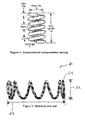
- Figure 1 illustrates the basic geometric parameters defining a helical compression spring.
- the primary spring geometric design parameters are: Free Length (L o ) representing the length of the unloaded spring; Diameter (d) representing the diameter of the wire or other material that is wound into the helical spring; Coil Diameter (D) representing the mean diameter of the helical spring, i.e., (D outer + D inner )/2; and Total Number of Coils (N t ) representing the number of turns in the helical spring.
- Active Coils representing the number of coils which deform when the spring is loaded, as opposed to the inactive turns at each end which are in contact with the spring seat or base, but do not substantially deform
- Solid Length L s
- Pitch representing the distance from center to center of the wire in adjacent active coils.
- Springs in seating and resting surfaces of articles of furniture typically employ closed end springs of the type illustrated in Figure 1 . Closed end springs typically have at most one inactive coil at each end of the spring.
- the selection of the spring material is usually the first step in parametric spring design. Material selection may be based on a number of factors, including temperature range, tensile strength, elastic modulus, fatigue life, corrosion resistance, cost, etc.
- High-carbon spring steels are the most commonly used of all springs materials. They are relatively inexpensive, readily available, and easily worked. Examples include Music (ASTM A228) wire and Hard Drawn (ASTM A227) wire, which are suitable for springs used, for example, in mattresses. Spring wires can be surface-treated, such as by being galvanized or coated with a plastic or epoxy.
- Spring wire used in mattress coil spring construction typically has a diameter of between about 0.06" (16 gauge, 1.524 millimeters) and about 0.09" (13 gauge, 2.286 millimeters), with each coil spring made of a single strand of spring wire.
- the exact design parameters for mattress coil springs depend, for example, on the desired firmness, which is in addition determined by the number of springs per unit surface area of the mattress.
- Both single strand and, according to the invention, multi-strand coils can be designed to have a variable spring rate, meaning that the spring excursion varies non-linearly with the applied load.
- FIG. 2 shows schematically a multi-strand coil spring 20.
- the coil spring 20 employs a multi-strand cord 22, which is bent to form the coil spring 20.
- the number of strands employed varies according to the application and the type of material used to form the strands.
- the cord 22 is formed from braiding three or more strands.
- the multi-strand cord 22 includes from three to about fifty braided strands. As described below, testing by applicants has shown that coil springs formed from multi-strand cords, braided or twisted, have improved performance characteristics over conventional single strand spring.
- An exemplary free length Lo 26 is between about 5" and about 6".
- the spring 20 can be made, for example, of carbon steel, such as ASTM
- the fatigue performance of the illustrated multi-strand spring design is estimated to be between about 100,000 and about 1,000,000 operation cycles at about 2.75" (7cm) deflection, which corresponds to a useful life of about 15 years.
- the efficiency and performance of the spring is understood to increase with the number of strands.
- the cost also tends to increase with the number of strands.
- a significant advantage of the invention is that multi-strand springs are essentially fault tolerant in that they remain functional even when one or more of the strands break.
- the strands may be twisted, woven, clipped or bonded together, and any suitable method for forming the multi-strand coil spring may be employed without departing from the scope of the invention.
- the strands may be formed, for example, from steel, aluminum, plastic, copper, titanium, rubber or any other suitable material, with the type of material selected depending on the application at hand.
- the strands may have an ovular, circular, hexagonal, square, flattened version of any of the preceding or any other suitable cross-sectional geometry, and may be formed into any number of coils.
- the strand gauge may vary according to the application, and in one embodiment is about 710 gauge (6.76cm), although other gauges may be used.
- the coils themselves may be formed as active or inactive coils, and may all have substantially equal Coil Diameters (D).
- the Coil Diameter (D) may vary from coil to coil, and may be arranged, for example to have sequentially increasing Coil Diameters (D), Sequentially decreasing Coil Diameters, or some combination of both, to form any suitable coil diameter pattern, for example, for forming a coil spring having a variable spring rate. Other ways to form coils having a variable spring rate are discussed below with respect to Figure 6 .
- the coils are depicted as being substantially circular in geometry, they may be oval, hexagonal, rectangular, square or any other suitable geometry.
- the Pitch (P) is depicted in Figure 2 as being substantially constant from active coil to active coil, this need not be the case and the pitch may vary from active coil to active coil.
- the exemplary multi-strand coil spring 20 can be fabricated by initially providing the individual strands with a helical twist prior to the cording operation.
- the helix of the multi-strand spring preferably opposes the helix of the individual strands to counteract a tendency of the strands to loosen when the spring is operated, i.e., compressed. Additionally, as with conventional springs, a torque is applied to the cord during coiling.
- coiling may be achieved by passing a braided cord through a coiler, such as the type of coiler employed for forming steel mattress coils, wherein a heavy-gauge steel wire is compressed into a barrel-shaped coil such that no turns touch for eliminating noise and vibration.
- Coils are passed to a pocketing machine or station to pocket the springs into individual sleeves of a non-woven, non-allergenic fabric such as Duon.
- Each sleeve is ultrasonically sealed by a process where the fibers are melted together to form solid plastic seams, which are secure and tear-resistant.
- the coils are then fusion bonded to produce a strong, stable construction.
- the number of coils in each unit may vary, and the types of coils and the number of strands and gauge of strands can vary from pocket to pocket, and multi-strand coils may be employed in combination with single strand coils.
- the individual strands are connected to each other at least at the ends of the coil. Since the strands can rub against each other over the length of the coil, which can cause fretting and premature wear, the strands may be coated and/or pre-galvanized or otherwise treated. Moreover, the multi-strand coil may also be sealed/coated with a sealant, such as an epoxy.
- the various strands of the multi-strand coil spring 20 may be made of differing materials, for example, different types of metals, such as bronze, titanium and the like, as well as various types of spring steels having different elastic properties.
- different types of metals such as bronze, titanium and the like
- spring steels having different elastic properties.
- Other elastic materials having spring-like properties for example suitable plastics, may also be used.
- the strands can be selectively welded at predetermined locations along the length of the multi-strand cord, either when the multi-strand cord is fabricated or when the coil is being formed.
- the coil can thereafter be coated or galvanized along the multi-strand cord.
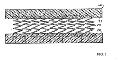
- Figure 3 depicts a section of a mattress 20 constructed with multi-strand wire coils 26 whereby additional support is provided by encasing at least the end sections of the springs in the foam 22, 24.
- Other resilient materials such as rubber and/or latex, can also be used.
- This arrangement obviates the need for connecting the ends of the springs individually to a frame or to each other and can furthermore provide a sleeping surface adapted for the comfort of a user.
- the illustrative construction advantageously provides additional lateral support for the multi-strand coils.
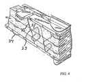
- support for the multi-strand coil springs and the mattress construction in general may also be improved by placing foam 30 between or around the coil springs 34, for example, by slitting the foam 30 substantially parallel (32a, 32b, 32c) to the spring turns (see Figure 5 ) and pressing the foam into the sides of the coil spring.
- This approach makes it possible to reduce the number of springs in a mattress, thereby reducing also the weight and the manufacturing costs of the mattress.
- spring elements 39 such as vertical springs
- the orientation of the slits can be arranged so as to match the orientation of the individual sections 33, 35 of the spring elements.
- adjacent springs 34 and/or spring elements 39 can be connected in an alternating arrangement, whereby a top section of a spring element 39 is connected to the top section of an adjacent spring element 39 by cross-wire 38, with the bottom section of a top-connected spring element 39 then connected to a bottom section of the next spring element 39 (not shown), and so on.
- a succession of springs can be manufactured from a continuous wire (either solid or braided/stranded) without separating the individual springs.
- Figure 5 illustrates that the multi-strand springs 34 may be arranged in a row that extends along at least a portion of the length of the mattress.
- the multi-strand springs 34 are arranged as an edge support disposed at the peripheral edge of the mattress and capable of providing a more robust and firm edge for the mattress.
- the multi-strand springs may have a spring constant that is greater than the spring constant of other springs employed within the mattress.
- the firmness of the multi-strand springs 34 may be selected for the intended purpose of providing greater support, and in particular, sufficient support to allow a person to sit comfortably on the edge of the mattress, without the mattress edge collapsing under the person's weight.
- the edge support may be provided to the lateral edges of the mattress or may be applied around the full periphery of the mattress.
- Figure 6 illustrates an exemplary embodiment of a spring 60, which can have a variable spring rate.
- the multi-strand wire coils of the invention can be employed in the design of such a spring.
- a spring 60 with a variable spring rate can provide a mattress sleeping surface that has a "soft" response if less pressure exerted by a user (i.e. if the weight of the user is relatively low), with the response becoming "harder” for heavier users.
- a first section 62 of the spring 60 may be manufactured, for example, from a solid coil wire having a first, typically lower spring rate (stiffer spring).
- a second section 64 may be implemented, for example, as a multi-strand coil wire and attached to an end of the section 62, for example, by crimping a sleeve 66 over the adjoining end portions of each section 62, 64.
- the sleeve 66 can be made of metal or a sturdy plastic that can withstand the applied torsion and other forces.
- Other means for connecting the sections 62 and 64, with or without a sleeve 66 may include, for example, welding or brazing.
- multi-strand coil springs have a greater spring rate than single strand coil springs.
- the spring 60 can be configured such that the multi-strand section 64 compresses under a first load, giving the "soft" response, and the single strand section 62 thereafter compresses under an increased load relative to the first load to provide the "harder" response relative to the section 64.
- the response can be further adjusted, for example, by inserting foam (30; see FIGS. 4 and 5 ), as described above.
- a multi-strand coil 72 is inserted into and/or affixed inside another (multi-strand wire) coil spring 74 of a larger diameter to create a combined spring 70.
- the combined spring 70 can be configured to have a desired constant or variable spring rate, thus providing similar advantages to the hybrid spring 60 of Figure 6 .
- Either or both coil springs 72 and 74 can be made from a multi-strand cord, braided cord or single strand, or can have the split coil configuration depicted in Figure 6 .
- a mattress core or other resting surface of an article of furniture may be manufactured by first arranging outer coil springs in a desired pattern and then selectively placing multi-strand wire coils inside the outer coil springs.
- the inner coils can be secured to the outer coils in a conventional manner, for example, with hog rings, wire, straps, etc.
- the manufacture may be particularly simplified by using the foam construction depicted in Figures 3-5 , in which case the inner coil springs may simply be placed inside the outer springs without additional mechanical attachment to the outer coil spring, before the foam is applied.
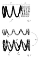
- Figures 8A and 8B show the exemplary multi-strand coil spring illustrated in Figure 2 during flexing. Testing results demonstrate that a three cord multi-strand coil spring having strands of steel with an average gauge will withstand about 4.4 million coil flexes from a height of about 9.75 inches (24.8cm) ( Figure 8A ) to a height of about 1.5 inches (3.8cm) ( Figure 8B ) without separation.
- the coil spring is formed utilizing a commercial coller machine and the steel strands have no bands or coating.
- Multi-strand coil springs of the type utilized possess adequate performance characteristics for a wide variety of coiled spring applications and may be tailored to specifically perform even more applications. Such applications include furniture uses, particularly rest surfaces, such as mattresses exemplified by the previously discussed embodiments.
- the multi-strand springs described above can be formed from a multi-strand cord using a suitable coil winding machine that eliminates torsion in the feed cord, such as the coil winding machine disclosed in commonly assigned U.S. Serial No. 10/661,363 , entitled methods for Manufacturing Coil Spring":
- Such continuous coils from multi-strand wire may perform best if wound by maintaining the same winding sense between coils so as to prevent the individual strands from loosening during spring compression.
Landscapes
- Engineering & Computer Science (AREA)
- General Engineering & Computer Science (AREA)
- Mechanical Engineering (AREA)
- Mattresses And Other Support Structures For Chairs And Beds (AREA)
- Springs (AREA)
- Wire Processing (AREA)
Claims (6)
- Spiralfederanordnung (20), geeignet für Matratzenanordnungen, die Folgendes umfasst:mehrere Litzen, die entweder miteinander verdreht oder verflochten sind, um eine Mehrlitzenschnur (22) zu bilden, wobei die Mehrlitzenschnur zu einer ersten Schraubenfeder mit vier oder mehr aktiven Windungen gewickelt ist;wobei die Schraubenfeder Folgendes umfasst:mindestens eine inaktive Windung (24), die ein geschlossenes Ende bildet und eine freie Länge von mindestens vier Zoll (101,6 mm) aufweist;dadurch gekennzeichnet, dass:die Schraubenfeder tonnenförmig ist und taschenartig in einer Hülle aufgenommen ist, um die Spiralfederanordnung zu erzeugen, wobei die Hülle aus einem nicht allergenen Vliesmaterial gebildet ist.
- Spiralfederanordnung (20) nach Anspruch 1, wobei die mehreren Litzen aus dem gleichen Material gebildet sind.
- Spiralfederanordnung (20) nach Anspruch 1, wobei mindestens eine der mehreren Litzen aus einem anderen Material gebildet sind als mindestens eine andere der mehreren Litzen.
- Spiralfederanordnung (20) nach Anspruch 1, wobei mindestens eine der mehreren Litzen mehrere Segmente aufweist, wobei mindestens eines der Segmente aus einem anderen Material gebildet ist als mindestens eine andere der mehreren Segmente.
- Spiralfederanordnung (20) nach Anspruch 1, wobei die Mehrlitzenschnur mehrere Segmente aufweist, wobei mindestens eines der Segmente aus einem anderen Material gebildet ist als mindestens eine andere der mehreren Segmente, um eine veränderliche Federkonstante vorzusehen.
- Spiralfederanordnung (20) nach Ansprüchen 1-5, wobei die Mehrlitzenschnur eine Beschichtung aufweist.
Applications Claiming Priority (7)
| Application Number | Priority Date | Filing Date | Title |
|---|---|---|---|
| US10/371,177 US7047581B2 (en) | 2003-02-19 | 2003-02-19 | Stranded mattress spring |
| US371177 | 2003-02-19 | ||
| US688852 | 2003-10-15 | ||
| US10/688,852 US6944899B2 (en) | 2003-02-19 | 2003-10-15 | Stranded mattress spring |
| US51211503P | 2003-10-17 | 2003-10-17 | |
| US512115P | 2003-10-17 | ||
| PCT/US2004/004962 WO2004074706A2 (en) | 2003-02-19 | 2004-02-19 | Multi-stranded coil spring |
Related Child Applications (1)
| Application Number | Title | Priority Date | Filing Date |
|---|---|---|---|
| EP10184048 Division-Into | 2010-09-30 |
Publications (4)
| Publication Number | Publication Date |
|---|---|
| EP1599683A3 EP1599683A3 (de) | 2005-10-13 |
| EP1599683A2 EP1599683A2 (de) | 2005-11-30 |
| EP1599683A4 EP1599683A4 (de) | 2006-06-28 |
| EP1599683B1 true EP1599683B1 (de) | 2016-01-13 |
Family
ID=44073469
Family Applications (1)
| Application Number | Title | Priority Date | Filing Date |
|---|---|---|---|
| EP04712878.0A Expired - Lifetime EP1599683B1 (de) | 2003-02-19 | 2004-02-19 | Mehrstrangschraubenfeder |
Country Status (6)
| Country | Link |
|---|---|
| EP (1) | EP1599683B1 (de) |
| JP (2) | JP2006518829A (de) |
| AU (1) | AU2004201650B2 (de) |
| CA (1) | CA2484536C (de) |
| MX (1) | MXPA05008816A (de) |
| WO (1) | WO2004074706A2 (de) |
Families Citing this family (13)
| Publication number | Priority date | Publication date | Assignee | Title |
|---|---|---|---|---|
| FR2891884A1 (fr) * | 2005-10-12 | 2007-04-13 | Peugeot Citroen Automobiles Sa | Ressort helicoidal pour volant a commandes centrales fixes de vehicule automobile |
| EP2418985B1 (de) * | 2009-04-14 | 2016-03-09 | Sealy Technology LLC | Spule-in-spule-federn und innenfedern dafür |
| US8382534B2 (en) * | 2010-04-22 | 2013-02-26 | Saint-Gobain Performance Plastics Corporation | System, method and apparatus for stranded canted coil spring |
| GB201102187D0 (en) * | 2011-02-09 | 2011-03-23 | Harrison Spinks Components Ltd | Multi-purpose resiient pad |
| KR101391940B1 (ko) * | 2011-05-05 | 2014-05-30 | 씨스톤 테크놀로지스(주) | 토션댐퍼 |
| WO2013107034A1 (zh) * | 2012-01-20 | 2013-07-25 | 成都优阳机电产品设计有限公司 | 柔性支撑轴 |
| KR101727554B1 (ko) | 2015-03-06 | 2017-04-17 | (주) 비엠비 | 매트리스 |
| DE102016103800A1 (de) * | 2016-03-03 | 2017-09-07 | Brose Fahrzeugteile Gmbh & Co. Kg, Bamberg | Antriebsanordnung einer Klappenanordnung eines Kraftfahrzeugs |
| CN106725823A (zh) * | 2016-12-30 | 2017-05-31 | 苏州达力客自动化科技有限公司 | 一种软钻弹簧 |
| JP2021522529A (ja) * | 2018-04-30 | 2021-08-30 | ピーエーエスエムアール テクノロジー エー プロプリエタリー リミテッド | 放射線放出を処置するための装置及び方法 |
| KR102096072B1 (ko) * | 2018-10-29 | 2020-04-02 | 이창근 | 침대 매트리스 |
| KR102353642B1 (ko) * | 2021-03-22 | 2022-01-21 | 주식회사 모나미 | 동작소음 감음구조를 갖는 다색 필기구 |
| JP7580707B2 (ja) * | 2022-09-29 | 2024-11-12 | 康夫 飛松 | 束ねばね |
Family Cites Families (31)
| Publication number | Priority date | Publication date | Assignee | Title |
|---|---|---|---|---|
| US15869A (en) * | 1856-10-07 | Coiled spring fob railroad-cars | ||
| US99475A (en) * | 1870-02-01 | Improved railway-car spring | ||
| DE300804C (de) * | ||||
| US374658A (en) * | 1887-12-13 | Speings | ||
| US274715A (en) * | 1883-03-27 | buckley | ||
| US685160A (en) * | 1900-09-01 | 1901-10-22 | James Marshall | Mattress. |
| US683344A (en) * | 1901-04-20 | 1901-09-24 | Finlay Sim | Support for bed-netting. |
| US837751A (en) * | 1906-09-10 | 1906-12-04 | Edgar Webster Summers | Convertible spring seat and bed. |
| US1451936A (en) * | 1921-09-20 | 1923-04-17 | Leonard A Young | Method of forming compound springs |
| US2398237A (en) * | 1944-01-28 | 1946-04-09 | Marsack Patents Corp | Mattress |
| US2480158A (en) * | 1945-07-23 | 1949-08-30 | David T Owen | Spring and spring construction |
| DE815907C (de) * | 1950-01-01 | 1951-10-04 | Motorrad U Fahrradteilefabrik | Abfederung fuer Fahrzeuge, insbesondere fuer Kraftradgabeln |
| US2918271A (en) * | 1956-08-02 | 1959-12-22 | Rockwell Standard Co | Twisted spring elements |
| US3985097A (en) * | 1974-12-31 | 1976-10-12 | Acf Industries, Incorporated | Apparatus for coating workpieces with a plastic material |
| US4025681A (en) * | 1975-03-24 | 1977-05-24 | The Boeing Company | Environmentally durable metal honeycomb structure |
| CH637739A5 (en) * | 1978-08-26 | 1983-08-15 | Roehrs Werner Dr Kg | Elastomer-coated multi-wire spring |
| JPS5891940A (ja) * | 1981-11-27 | 1983-06-01 | Mitsubishi Rayon Co Ltd | 複合材料から成るコイル状バネ |
| US4473217A (en) * | 1982-01-07 | 1984-09-25 | Kato Hatsujo Kaisha, Limited | Fiber-reinforced resin coil spring and method of manufacturing the same |
| JPS5997333A (ja) * | 1982-11-25 | 1984-06-05 | Oi Seisakusho Co Ltd | ばね |
| JPS59170478A (ja) * | 1983-03-17 | 1984-09-26 | Nhk Spring Co Ltd | 熱応動装置 |
| US5098493A (en) * | 1986-11-10 | 1992-03-24 | Tayco Developments, Inc. | Method of fabricating springs formed of rope pressure-saturated or impregnated with binder |
| JPS63168335A (ja) * | 1986-12-30 | 1988-07-12 | Yokohama Rubber Co Ltd:The | コ−ド材料の巾出し装置 |
| US4889327B1 (en) * | 1988-03-15 | 1994-12-20 | Harris Trust And Savings Bank | Multiple-strand torsion spring |
| DE3900473A1 (de) * | 1989-01-10 | 1990-07-26 | Theodor Schroeder Federnfabrik | Schraubendruckfeder |
| JPH0366957A (ja) * | 1989-08-01 | 1991-03-22 | Nhk Spring Co Ltd | テンショナ |
| JPH0759236B2 (ja) * | 1990-06-29 | 1995-06-28 | オリンパス光学工業株式会社 | 内視鏡用処置具装置 |
| US5210890A (en) * | 1992-09-21 | 1993-05-18 | Tualatin Sleep Products | Mattress foundation with springs and foam elements |
| JPH10184751A (ja) * | 1996-12-27 | 1998-07-14 | Nhk Spring Co Ltd | 2段ピッチ圧縮コイルばね |
| JPH10213197A (ja) * | 1997-01-31 | 1998-08-11 | Koyo Seiko Co Ltd | オートテンショナ |
| US5868383A (en) * | 1997-03-27 | 1999-02-09 | L&P Property Management Company | Multiple rate coil spring assembly |
| JP2000023787A (ja) * | 1998-07-10 | 2000-01-25 | Aisin Seiki Co Ltd | マットレス |
-
2004
- 2004-02-19 CA CA2484536A patent/CA2484536C/en not_active Expired - Lifetime
- 2004-02-19 JP JP2005512628A patent/JP2006518829A/ja not_active Ceased
- 2004-02-19 WO PCT/US2004/004962 patent/WO2004074706A2/en not_active Ceased
- 2004-02-19 AU AU2004201650A patent/AU2004201650B2/en not_active Expired
- 2004-02-19 MX MXPA05008816A patent/MXPA05008816A/es active IP Right Grant
- 2004-02-19 EP EP04712878.0A patent/EP1599683B1/de not_active Expired - Lifetime
-
2010
- 2010-11-01 JP JP2010245095A patent/JP2011078793A/ja not_active Withdrawn
Also Published As
| Publication number | Publication date |
|---|---|
| CA2484536C (en) | 2013-08-13 |
| EP1599683A4 (de) | 2006-06-28 |
| JP2011078793A (ja) | 2011-04-21 |
| WO2004074706A2 (en) | 2004-09-02 |
| CA2484536A1 (en) | 2004-09-02 |
| MXPA05008816A (es) | 2005-10-18 |
| EP1599683A2 (de) | 2005-11-30 |
| WO2004074706A3 (en) | 2005-10-13 |
| AU2004201650A1 (en) | 2004-09-02 |
| AU2004201650B2 (en) | 2011-03-24 |
| AU2004201650A8 (en) | 2004-09-02 |
| JP2006518829A (ja) | 2006-08-17 |
Similar Documents
| Publication | Publication Date | Title |
|---|---|---|
| US8099811B2 (en) | Multi-stranded coil spring | |
| US6944899B2 (en) | Stranded mattress spring | |
| JP2011078793A (ja) | 複数撚り合わせコイルバネ | |
| US7047581B2 (en) | Stranded mattress spring | |
| EP2286107B1 (de) | Mikrolegierte feder | |
| CA2704203C (en) | Asymmetrical combined cylindrical and conical springs | |
| US20110148018A1 (en) | Asymmetrical combined cylindrical and conical springs | |
| WO1996012428A1 (en) | Innerspring construction with springs having free terminal convolutions | |
| EP2418985A1 (de) | Spule-in-spule-federn und innenfedern dafür | |
| CA2876037C (en) | Spring core having a fully active spring and method of manufacturing the same | |
| EP3937730A1 (de) | Komfortschicht mit einem sich wiederholenden muster von taschenminispiralfedern mit unterschiedlichen höhen | |
| US9044102B2 (en) | Spring core having border wire with generally rectangular cross-section | |
| HK1085363B (en) | Multi-stranded coil spring | |
| US20230389713A1 (en) | Mattress assembly including coil innerspring units, coil innerspring units, and processes for making the same | |
| US20120047657A1 (en) | Spring Assembly Having Continuous Bands of Springs |
Legal Events
| Date | Code | Title | Description |
|---|---|---|---|
| PUAI | Public reference made under article 153(3) epc to a published international application that has entered the european phase |
Free format text: ORIGINAL CODE: 0009012 |
|
| PUAK | Availability of information related to the publication of the international search report |
Free format text: ORIGINAL CODE: 0009015 |
|
| AK | Designated contracting states |
Kind code of ref document: A2 Designated state(s): AT BE BG CH CY CZ DE DK EE ES FI FR GB GR HU IE IT LI LU MC NL PT RO SE SI SK TR |
|
| AX | Request for extension of the european patent |
Extension state: AL LT LV MK |
|
| AK | Designated contracting states |
Kind code of ref document: A3 Designated state(s): AT BE BG CH CY CZ DE DK EE ES FI FR GB GR HU IE IT LI LU MC NL PT RO SE SI SK TR |
|
| AX | Request for extension of the european patent |
Extension state: AL LT LV MK |
|
| RIC1 | Information provided on ipc code assigned before grant |
Ipc: 7A 47C 27/04 A |
|
| RIN1 | Information on inventor provided before grant (corrected) |
Inventor name: DEFRANKS, MICHAEL, S. Inventor name: GLADNEY, RICHARD, F. Inventor name: KUCHEL, BERNHARD, W. |
|
| 17P | Request for examination filed |
Effective date: 20060314 |
|
| RBV | Designated contracting states (corrected) |
Designated state(s): AT BE BG CH CY CZ DE DK EE ES FI FR GB GR HU IE IT LI LU MC NL PT RO SE SI SK TR |
|
| DAX | Request for extension of the european patent (deleted) | ||
| A4 | Supplementary search report drawn up and despatched |
Effective date: 20060531 |
|
| REG | Reference to a national code |
Ref country code: HK Ref legal event code: DE Ref document number: 1085363 Country of ref document: HK |
|
| 17Q | First examination report despatched |
Effective date: 20080215 |
|
| GRAP | Despatch of communication of intention to grant a patent |
Free format text: ORIGINAL CODE: EPIDOSNIGR1 |
|
| INTG | Intention to grant announced |
Effective date: 20150717 |
|
| GRAS | Grant fee paid |
Free format text: ORIGINAL CODE: EPIDOSNIGR3 |
|
| GRAA | (expected) grant |
Free format text: ORIGINAL CODE: 0009210 |
|
| AK | Designated contracting states |
Kind code of ref document: B1 Designated state(s): AT BE BG CH CY CZ DE DK EE ES FI FR GB GR HU IE IT LI LU MC NL PT RO SE SI SK TR |
|
| REG | Reference to a national code |
Ref country code: GB Ref legal event code: FG4D |
|
| REG | Reference to a national code |
Ref country code: CH Ref legal event code: EP |
|
| REG | Reference to a national code |
Ref country code: IE Ref legal event code: FG4D |
|
| REG | Reference to a national code |
Ref country code: AT Ref legal event code: REF Ref document number: 769912 Country of ref document: AT Kind code of ref document: T Effective date: 20160215 |
|
| REG | Reference to a national code |
Ref country code: DE Ref legal event code: R096 Ref document number: 602004048503 Country of ref document: DE |
|
| REG | Reference to a national code |
Ref country code: FR Ref legal event code: PLFP Year of fee payment: 13 |
|
| REG | Reference to a national code |
Ref country code: NL Ref legal event code: MP Effective date: 20160113 |
|
| PG25 | Lapsed in a contracting state [announced via postgrant information from national office to epo] |
Ref country code: BE Free format text: LAPSE BECAUSE OF NON-PAYMENT OF DUE FEES Effective date: 20160229 |
|
| REG | Reference to a national code |
Ref country code: AT Ref legal event code: MK05 Ref document number: 769912 Country of ref document: AT Kind code of ref document: T Effective date: 20160113 |
|
| PG25 | Lapsed in a contracting state [announced via postgrant information from national office to epo] |
Ref country code: NL Free format text: LAPSE BECAUSE OF FAILURE TO SUBMIT A TRANSLATION OF THE DESCRIPTION OR TO PAY THE FEE WITHIN THE PRESCRIBED TIME-LIMIT Effective date: 20160113 |
|
| PG25 | Lapsed in a contracting state [announced via postgrant information from national office to epo] |
Ref country code: GR Free format text: LAPSE BECAUSE OF FAILURE TO SUBMIT A TRANSLATION OF THE DESCRIPTION OR TO PAY THE FEE WITHIN THE PRESCRIBED TIME-LIMIT Effective date: 20160414 Ref country code: ES Free format text: LAPSE BECAUSE OF FAILURE TO SUBMIT A TRANSLATION OF THE DESCRIPTION OR TO PAY THE FEE WITHIN THE PRESCRIBED TIME-LIMIT Effective date: 20160113 Ref country code: FI Free format text: LAPSE BECAUSE OF FAILURE TO SUBMIT A TRANSLATION OF THE DESCRIPTION OR TO PAY THE FEE WITHIN THE PRESCRIBED TIME-LIMIT Effective date: 20160113 |
|
| REG | Reference to a national code |
Ref country code: HK Ref legal event code: GR Ref document number: 1085363 Country of ref document: HK |
|
| PG25 | Lapsed in a contracting state [announced via postgrant information from national office to epo] |
Ref country code: PT Free format text: LAPSE BECAUSE OF FAILURE TO SUBMIT A TRANSLATION OF THE DESCRIPTION OR TO PAY THE FEE WITHIN THE PRESCRIBED TIME-LIMIT Effective date: 20160513 Ref country code: SE Free format text: LAPSE BECAUSE OF FAILURE TO SUBMIT A TRANSLATION OF THE DESCRIPTION OR TO PAY THE FEE WITHIN THE PRESCRIBED TIME-LIMIT Effective date: 20160113 Ref country code: AT Free format text: LAPSE BECAUSE OF FAILURE TO SUBMIT A TRANSLATION OF THE DESCRIPTION OR TO PAY THE FEE WITHIN THE PRESCRIBED TIME-LIMIT Effective date: 20160113 |
|
| REG | Reference to a national code |
Ref country code: CH Ref legal event code: PL |
|
| REG | Reference to a national code |
Ref country code: DE Ref legal event code: R097 Ref document number: 602004048503 Country of ref document: DE |
|
| PG25 | Lapsed in a contracting state [announced via postgrant information from national office to epo] |
Ref country code: MC Free format text: LAPSE BECAUSE OF FAILURE TO SUBMIT A TRANSLATION OF THE DESCRIPTION OR TO PAY THE FEE WITHIN THE PRESCRIBED TIME-LIMIT Effective date: 20160113 Ref country code: LI Free format text: LAPSE BECAUSE OF NON-PAYMENT OF DUE FEES Effective date: 20160229 Ref country code: EE Free format text: LAPSE BECAUSE OF FAILURE TO SUBMIT A TRANSLATION OF THE DESCRIPTION OR TO PAY THE FEE WITHIN THE PRESCRIBED TIME-LIMIT Effective date: 20160113 Ref country code: CH Free format text: LAPSE BECAUSE OF NON-PAYMENT OF DUE FEES Effective date: 20160229 Ref country code: DK Free format text: LAPSE BECAUSE OF FAILURE TO SUBMIT A TRANSLATION OF THE DESCRIPTION OR TO PAY THE FEE WITHIN THE PRESCRIBED TIME-LIMIT Effective date: 20160113 |
|
| PLBE | No opposition filed within time limit |
Free format text: ORIGINAL CODE: 0009261 |
|
| STAA | Information on the status of an ep patent application or granted ep patent |
Free format text: STATUS: NO OPPOSITION FILED WITHIN TIME LIMIT |
|
| PG25 | Lapsed in a contracting state [announced via postgrant information from national office to epo] |
Ref country code: SK Free format text: LAPSE BECAUSE OF FAILURE TO SUBMIT A TRANSLATION OF THE DESCRIPTION OR TO PAY THE FEE WITHIN THE PRESCRIBED TIME-LIMIT Effective date: 20160113 Ref country code: RO Free format text: LAPSE BECAUSE OF FAILURE TO SUBMIT A TRANSLATION OF THE DESCRIPTION OR TO PAY THE FEE WITHIN THE PRESCRIBED TIME-LIMIT Effective date: 20160113 Ref country code: CZ Free format text: LAPSE BECAUSE OF FAILURE TO SUBMIT A TRANSLATION OF THE DESCRIPTION OR TO PAY THE FEE WITHIN THE PRESCRIBED TIME-LIMIT Effective date: 20160113 |
|
| REG | Reference to a national code |
Ref country code: IE Ref legal event code: MM4A |
|
| 26N | No opposition filed |
Effective date: 20161014 |
|
| PG25 | Lapsed in a contracting state [announced via postgrant information from national office to epo] |
Ref country code: BE Free format text: LAPSE BECAUSE OF FAILURE TO SUBMIT A TRANSLATION OF THE DESCRIPTION OR TO PAY THE FEE WITHIN THE PRESCRIBED TIME-LIMIT Effective date: 20160113 |
|
| PG25 | Lapsed in a contracting state [announced via postgrant information from national office to epo] |
Ref country code: IE Free format text: LAPSE BECAUSE OF NON-PAYMENT OF DUE FEES Effective date: 20160219 |
|
| REG | Reference to a national code |
Ref country code: FR Ref legal event code: PLFP Year of fee payment: 14 |
|
| PG25 | Lapsed in a contracting state [announced via postgrant information from national office to epo] |
Ref country code: SI Free format text: LAPSE BECAUSE OF FAILURE TO SUBMIT A TRANSLATION OF THE DESCRIPTION OR TO PAY THE FEE WITHIN THE PRESCRIBED TIME-LIMIT Effective date: 20160113 Ref country code: BG Free format text: LAPSE BECAUSE OF FAILURE TO SUBMIT A TRANSLATION OF THE DESCRIPTION OR TO PAY THE FEE WITHIN THE PRESCRIBED TIME-LIMIT Effective date: 20160413 |
|
| REG | Reference to a national code |
Ref country code: FR Ref legal event code: PLFP Year of fee payment: 15 |
|
| PG25 | Lapsed in a contracting state [announced via postgrant information from national office to epo] |
Ref country code: CY Free format text: LAPSE BECAUSE OF FAILURE TO SUBMIT A TRANSLATION OF THE DESCRIPTION OR TO PAY THE FEE WITHIN THE PRESCRIBED TIME-LIMIT Effective date: 20160113 Ref country code: HU Free format text: LAPSE BECAUSE OF FAILURE TO SUBMIT A TRANSLATION OF THE DESCRIPTION OR TO PAY THE FEE WITHIN THE PRESCRIBED TIME-LIMIT; INVALID AB INITIO Effective date: 20040219 |
|
| PG25 | Lapsed in a contracting state [announced via postgrant information from national office to epo] |
Ref country code: TR Free format text: LAPSE BECAUSE OF FAILURE TO SUBMIT A TRANSLATION OF THE DESCRIPTION OR TO PAY THE FEE WITHIN THE PRESCRIBED TIME-LIMIT Effective date: 20160113 Ref country code: LU Free format text: LAPSE BECAUSE OF NON-PAYMENT OF DUE FEES Effective date: 20160219 |
|
| PGFP | Annual fee paid to national office [announced via postgrant information from national office to epo] |
Ref country code: FR Payment date: 20230328 Year of fee payment: 20 |
|
| PGFP | Annual fee paid to national office [announced via postgrant information from national office to epo] |
Ref country code: IT Payment date: 20230221 Year of fee payment: 20 Ref country code: GB Payment date: 20230327 Year of fee payment: 20 Ref country code: DE Payment date: 20230329 Year of fee payment: 20 |
|
| P01 | Opt-out of the competence of the unified patent court (upc) registered |
Effective date: 20230703 |
|
| REG | Reference to a national code |
Ref country code: DE Ref legal event code: R071 Ref document number: 602004048503 Country of ref document: DE |
|
| REG | Reference to a national code |
Ref country code: GB Ref legal event code: PE20 Expiry date: 20240218 |
|
| PG25 | Lapsed in a contracting state [announced via postgrant information from national office to epo] |
Ref country code: GB Free format text: LAPSE BECAUSE OF EXPIRATION OF PROTECTION Effective date: 20240218 |