EP1599669B1 - Fuel injection valve - Google Patents
Fuel injection valve Download PDFInfo
- Publication number
- EP1599669B1 EP1599669B1 EP03767438A EP03767438A EP1599669B1 EP 1599669 B1 EP1599669 B1 EP 1599669B1 EP 03767438 A EP03767438 A EP 03767438A EP 03767438 A EP03767438 A EP 03767438A EP 1599669 B1 EP1599669 B1 EP 1599669B1
- Authority
- EP
- European Patent Office
- Prior art keywords
- ejection openings
- fuel
- another
- respect
- valve
- Prior art date
- Legal status (The legal status is an assumption and is not a legal conclusion. Google has not performed a legal analysis and makes no representation as to the accuracy of the status listed.)
- Expired - Lifetime
Links
- 239000000446 fuel Substances 0.000 title claims description 63
- 238000002347 injection Methods 0.000 title claims description 39
- 239000007924 injection Substances 0.000 title claims description 39
- 238000002485 combustion reaction Methods 0.000 claims description 18
- 238000000034 method Methods 0.000 claims description 12
- 238000009826 distribution Methods 0.000 claims description 4
- 238000007789 sealing Methods 0.000 claims description 4
- 239000007921 spray Substances 0.000 description 14
- 239000000203 mixture Substances 0.000 description 8
- 238000004939 coking Methods 0.000 description 5
- 238000007906 compression Methods 0.000 description 2
- 230000005484 gravity Effects 0.000 description 2
- 238000009825 accumulation Methods 0.000 description 1
- 230000015572 biosynthetic process Effects 0.000 description 1
- 230000015556 catabolic process Effects 0.000 description 1
- 230000003750 conditioning effect Effects 0.000 description 1
- 238000010276 construction Methods 0.000 description 1
- 238000013016 damping Methods 0.000 description 1
- 238000006731 degradation reaction Methods 0.000 description 1
- 230000001419 dependent effect Effects 0.000 description 1
- 230000006866 deterioration Effects 0.000 description 1
- 230000000694 effects Effects 0.000 description 1
- 230000005284 excitation Effects 0.000 description 1
- 230000001788 irregular Effects 0.000 description 1
- 238000004519 manufacturing process Methods 0.000 description 1
- 230000035515 penetration Effects 0.000 description 1
- 238000001556 precipitation Methods 0.000 description 1
- 238000002360 preparation method Methods 0.000 description 1
Images

Classifications
-
- F—MECHANICAL ENGINEERING; LIGHTING; HEATING; WEAPONS; BLASTING
- F02—COMBUSTION ENGINES; HOT-GAS OR COMBUSTION-PRODUCT ENGINE PLANTS
- F02M—SUPPLYING COMBUSTION ENGINES IN GENERAL WITH COMBUSTIBLE MIXTURES OR CONSTITUENTS THEREOF
- F02M61/00—Fuel-injectors not provided for in groups F02M39/00 - F02M57/00 or F02M67/00
- F02M61/16—Details not provided for in, or of interest apart from, the apparatus of groups F02M61/02 - F02M61/14
- F02M61/18—Injection nozzles, e.g. having valve seats; Details of valve member seated ends, not otherwise provided for
- F02M61/1806—Injection nozzles, e.g. having valve seats; Details of valve member seated ends, not otherwise provided for characterised by the arrangement of discharge orifices, e.g. orientation or size
- F02M61/1846—Dimensional characteristics of discharge orifices
-
- F—MECHANICAL ENGINEERING; LIGHTING; HEATING; WEAPONS; BLASTING
- F02—COMBUSTION ENGINES; HOT-GAS OR COMBUSTION-PRODUCT ENGINE PLANTS
- F02M—SUPPLYING COMBUSTION ENGINES IN GENERAL WITH COMBUSTIBLE MIXTURES OR CONSTITUENTS THEREOF
- F02M51/00—Fuel-injection apparatus characterised by being operated electrically
- F02M51/06—Injectors peculiar thereto with means directly operating the valve needle
- F02M51/061—Injectors peculiar thereto with means directly operating the valve needle using electromagnetic operating means
- F02M51/0625—Injectors peculiar thereto with means directly operating the valve needle using electromagnetic operating means characterised by arrangement of mobile armatures
- F02M51/0664—Injectors peculiar thereto with means directly operating the valve needle using electromagnetic operating means characterised by arrangement of mobile armatures having a cylindrically or partly cylindrically shaped armature, e.g. entering the winding; having a plate-shaped or undulated armature entering the winding
- F02M51/0671—Injectors peculiar thereto with means directly operating the valve needle using electromagnetic operating means characterised by arrangement of mobile armatures having a cylindrically or partly cylindrically shaped armature, e.g. entering the winding; having a plate-shaped or undulated armature entering the winding the armature having an elongated valve body attached thereto
- F02M51/0675—Injectors peculiar thereto with means directly operating the valve needle using electromagnetic operating means characterised by arrangement of mobile armatures having a cylindrically or partly cylindrically shaped armature, e.g. entering the winding; having a plate-shaped or undulated armature entering the winding the armature having an elongated valve body attached thereto the valve body having cylindrical guiding or metering portions, e.g. with fuel passages
-
- F—MECHANICAL ENGINEERING; LIGHTING; HEATING; WEAPONS; BLASTING
- F02—COMBUSTION ENGINES; HOT-GAS OR COMBUSTION-PRODUCT ENGINE PLANTS
- F02M—SUPPLYING COMBUSTION ENGINES IN GENERAL WITH COMBUSTIBLE MIXTURES OR CONSTITUENTS THEREOF
- F02M61/00—Fuel-injectors not provided for in groups F02M39/00 - F02M57/00 or F02M67/00
- F02M61/16—Details not provided for in, or of interest apart from, the apparatus of groups F02M61/02 - F02M61/14
- F02M61/18—Injection nozzles, e.g. having valve seats; Details of valve member seated ends, not otherwise provided for
- F02M61/1806—Injection nozzles, e.g. having valve seats; Details of valve member seated ends, not otherwise provided for characterised by the arrangement of discharge orifices, e.g. orientation or size
- F02M61/1833—Discharge orifices having changing cross sections, e.g. being divergent
-
- F—MECHANICAL ENGINEERING; LIGHTING; HEATING; WEAPONS; BLASTING
- F02—COMBUSTION ENGINES; HOT-GAS OR COMBUSTION-PRODUCT ENGINE PLANTS
- F02M—SUPPLYING COMBUSTION ENGINES IN GENERAL WITH COMBUSTIBLE MIXTURES OR CONSTITUENTS THEREOF
- F02M61/00—Fuel-injectors not provided for in groups F02M39/00 - F02M57/00 or F02M67/00
- F02M61/16—Details not provided for in, or of interest apart from, the apparatus of groups F02M61/02 - F02M61/14
- F02M61/18—Injection nozzles, e.g. having valve seats; Details of valve member seated ends, not otherwise provided for
- F02M61/1853—Orifice plates
Definitions
- the DE 101 18 163 A1 discloses a multi-hole fuel injection valve in which the injection orifices are mounted so that the mixture flows circulating in the combustion chamber are shielded from the injection orifices of the multi-hole fuel injection valve and thereby no fuel can settle in the region of the injection openings.
- the ejection openings are surrounded in one embodiment at the end face of the valve seat body by a ring wall and in another embodiment, the same effect is achieved by lowering the outlets, so that the injection orifices relative to the end face of the valve seat body are reset.
- the fuel injection valve 1 consists of a nozzle body 2, in which a valve needle 3 is arranged.
- the valve needle 3 is in operative connection with a valve closing body 4, which cooperates with a arranged on a valve seat body 5 valve seat surface 6 to a sealing seat.
- the valve closing body is formed almost spherical and thereby contributes to an offset-free guidance in the valve seat body 5.
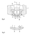
- the fuel injection valve 1 is an inwardly opening fuel injection valve 1, which has two injection openings 7.
- the spray openings 7 open according to the invention in extensions 38 in the valve seat body 5, which serve as coking.
- a detailed illustration of the spray openings 7 is the Fig. 2 and the following description.
- the armature 20 drops after sufficient degradation of the magnetic field by the pressure of the return spring 23 on the first flange 21 from the inner pole 13, whereby the valve needle 3 moves against the stroke direction.
- the valve closing body 4 is seated on the valve seat surface 6 and the fuel injection valve 1 is closed.
- the armature 20 is seated on the anchor stop formed by the second flange 34.
- the entirety of all spray openings 7 injects a mixture cloud into the combustion chamber whose center of gravity axis can be inclined in any spatial direction with respect to a longitudinal axis 37 of the fuel injection valve 1 between 0 ° and 70 ° and whose conical expansion is between 30 ° and 100 °.
Description
Die Erfindung geht aus von einem Brennstoffeinspritzventil nach der Gattung des Hauptanspruchs.The invention relates to a fuel injection valve according to the preamble of the main claim.
Beispielsweise ist aus der
Nachteilig an dem aus der obengenannten Druckschrift bekannten Brennstoffeinspritzventil sind insbesondere die eingeschränkten Eingriffsmöglichkeiten bei der Formung der Gemischwolke. Außer einer Variation der Strahlaufweitung und der Ausrichtung der Schwerpunktsachse der Gemischwolke ist es kaum möglich, auf Abweichungen von der Kegelform in Form von unregelmäßigen Gemischwolken und heterogen verteilte Strahlpenetration Einfluß zu nehmen. Dementsprechend sind die Möglichkeiten zur Reduktion des Brennstoffverbrauchs oder der Abgasemission gering.A disadvantage of the fuel injection valve known from the above-mentioned document in particular the limited intervention options in the formation of the Mixture cloud. Apart from a variation of the beam expansion and the orientation of the center of gravity of the mixture cloud, it is hardly possible to influence deviations from the conical shape in the form of irregular mixture clouds and heterogeneously distributed beam penetration. Accordingly, the possibilities for reducing fuel consumption or exhaust emission are low.
Die
Das erfindungsgemäße Verfahren zum Betreiben eines Brennstoffeinspritzventils mit den kennzeichnenden Merkmalen des Hauptanspruchs hat demgegenüber den Vorteil, daß durch einen hohen Brennstoffdruck in der Brennstoffverteilerleitung eine Gemischwolke mit hoher Zerstäubungsgüte für ein strahlgeführtes Brennverfahren erzeugt werden kann, ohne die bei Brennstoffeinspritzventilen mit Dralleinsatz auftretenden Nachteile wie hohen Brennstoffverbrauch, Verkokung der Ventilspitze oder erhöhte Abgasemissionen in Kauf nehmen zu müssen.The inventive method for operating a fuel injection valve having the characterizing features of the main claim has the advantage that a mixture cloud with high Zerstäubungsgüte can be generated by a high fuel pressure in the fuel distribution line for a spray-guided combustion process, without the disadvantages occurring in fuel injection valves with swirl insert disadvantages such as high fuel consumption . Coking of the valve tip or increased exhaust emissions to accept.
Die Abspritzöffnungen münden in Erweiterungen aus, welche vorteilhafterweise für einen wirksamen Verkokungsschutz im Mündungsbereich der Abspritzöffnungen sorgen.The injection openings open into extensions, which advantageously provide effective coking protection in the mouth region of the injection openings.
Durch ein definiertes Verhältnis der Gesamtlänge 1 bzw. der reduzierten Länge 1' zuströmseitig der Erweiterungen und des Durchmessers d der Abspritzöffnungen l:d kann sichergestellt werden, daß eine optimal Strahlaufbereitung möglich ist.By means of a defined ratio of the total length 1 or the reduced length 1 'on the inflow side of the extensions and of the diameter d of the spray-discharge openings 1: d, it can be ensured that optimum jet conditioning is possible.
Durch die in den Unteransprüchen aufgeführten Maßnahmen sind vorteilhafte Weiterbildungen des im Hauptanspruch angegebenen Brennstoffeinspritzventils möglich.The measures listed in the dependent claims advantageous refinements of the fuel injection valve specified in the main claim are possible.
Vorteilhafterweise können die zumindest zwei Abspritzöffnungen in beliebiger Weise in dem Ventilsitzkörper angebracht werden, z. B. auf konzentrischen oder exzentrischen Lochkreisen oder - ellipsen oder auf geraden oder gebogenen Reihen.Advantageously, the at least two ejection openings can be mounted in any desired manner in the valve seat body, for. On concentric or eccentric bolt circles or ellipses or on straight or curved rows.
Zudem können die Mittelpunkte der Abspritzöffnungen äquidistant oder unterschiedlich weit voneinander beabstandet sein, ebenso, wie die Orientierung der Achsen der Abspritzöffnungen beliebig sein kann.In addition, the centers of the injection orifices can be equidistant or spaced differently from each other, as well as the orientation of the axes of the injection orifices may be arbitrary.
Vorteilhafterweise ist keine der Abspritzöffnungen auf die Zündkerze gerichtet, so daß eine Verkokung der Funkenstrecke und eine verkürzte Lebensdauer vermieden werden können.Advantageously, none of the spray openings is directed to the spark plug, so that a coking of the spark gap and a shortened life can be avoided.
Ein Ausführungsbeispiel der Erfindung ist in der Zeichnung vereinfacht dargestellt und in der nachfolgenden Beschreibung näher erläutert. Es zeigt:
- Fig. 1
- einen schematischen Schnitt durch ein Ausführungsbeispiel eines erfindungsgemäß ausgestalteten Brennstoffeinspritzventils in einer Gesamtansicht,
- Fig. 2
- einen Ausschnitt aus dem in
Fig. 1 dargestellten Ausführungsbeispiel eines erfindungsgemäß ausgestalteten Brennstoffeinspritzventils im Bereich II inFig. 1 , und - Fig. 3
- einen vergrößerten Ausschnitt aus
Fig. 2 im Bereich III.
- Fig. 1
- FIG. 2 shows a schematic section through an exemplary embodiment of a fuel injection valve designed according to the invention in an overall view, FIG.
- Fig. 2
- a section of the in
Fig. 1 illustrated embodiment of an inventively designed fuel injection valve in the area II inFig. 1 , and - Fig. 3
- an enlarged section
Fig. 2 in area III.
Das Brennstoffeinspritzventil 1 besteht aus einem Düsenkörper 2, in welchem eine Ventilnadel 3 angeordnet ist. Die Ventilnadel 3 steht in Wirkverbindung mit einem Ventilschließkörper 4, der mit einer auf einem Ventilsitzkörper 5 angeordneten Ventilsitzfläche 6 zu einem Dichtsitz zusammenwirkt. Der Ventilschließkörper ist nahezu kugelförmig ausgebildet und trägt dadurch zu einer versatzfreien Führung im Ventilsitzkörper 5 bei. Bei dem Brennstoffeinspritzventil 1 handelt es sich im Ausführungsbeispiel um ein nach innen öffnendes Brennstoffeinspritzventil 1, welches über zwei Abspritzöffnungen 7 verfügt. Die Abspritzöffnungen 7 münden dabei erfindungsgemäß in Erweiterungen 38 im Ventilsitzkörper 5 aus, welche als Verkokungsschutz dienen. Eine detaillierte Darstellung der Abspritzöffnungen 7 ist der
Der Düsenkörper 2 ist durch eine Dichtung 8 gegen einen Außenpol 9 einer Magnetspule 10 abgedichtet. Die Magnetspule 10 ist in einem Spulengehäuse 11 gekapselt und auf einen Spulenträger 12 gewickelt, welcher an einem Innenpol 13 der Magnetspule 10 anliegt. Der Innenpol 13 und der Außenpol 9 sind durch einen Spalt 26 voneinander getrennt und stützen sich auf einem Verbindungsbauteil 29 ab. Die Magnetspule 10 wird über eine Leitung 19 von einem über einen elektrischen Steckkontakt 17 zuführbaren elektrischen Strom erregt. Der Steckkontakt 17 ist von einer Kunststoffummantelung 18 umgeben, die am Innenpol 13 angespritzt sein kann.The
Die Ventilnadel 3 ist in einer Ventilnadelführung 14 geführt, welche scheibenförmig ausgeführt ist. Zur Hubeinstellung dient eine zugepaarte Einstellscheibe 15. An der anderen Seite der Einstellscheibe 15 befindet sich ein Anker 20. Dieser steht über einen ersten Flansch 21 kraftschlüssig mit der Ventilnadel 3 in Verbindung, welche durch eine Schweißnaht 22 mit dem ersten Flansch 21 verbunden ist. Auf dem ersten Flansch 21 stützt sich eine Rückstellfeder 23 ab, welche in der vorliegenden Bauform des Brennstoffeinspritzventils 1 durch eine Hülse 24 auf Vorspannung gebracht wird.The
Abströmseitig des Ankers 20 ist ein zweiter Flansch 34 angeordnet, der als unterer Ankeranschlag dient. Er ist über eine Schweißnaht 35 kraftschlüssig mit der Ventilnadel 3 verbunden. Zwischen dem Anker 20 und dem zweiten Flansch 34 ist ein elastischer Zwischenring 33 zur Dämpfung von Ankerprellern beim Schließen des Brennstoffeinspritzventils 1 angeordnet.Downstream of the
In der Ventilnadelführung 14 und im Anker 20 verlaufen Brennstoffkanäle 30 und 31. Am Ventilschließkörper 4 sind Anschliffe 32 ausgebildet, welche den Brennstoff zum Dichtsitz führen. Der Brennstoff wird über eine zentrale Brennstoffzufuhr 16 zugeführt und durch ein Filterelement 25 gefiltert. Das Brennstoffeinspritzventil 1 ist durch eine Dichtung 28 gegen eine nicht weiter dargestellte Verteilerleitung abgedichtet. Eine weitere Dichtung 36 dichtet gegen den ebenfalls nicht weiter dargestellten Zylinderkopf der Brennkraftmaschine ab.In the
Im Ruhezustand des Brennstoffeinspritzventils 1 wird der erste Flansch 21 an der Ventilnadel 3 von der Rückstellfeder 23 entgegen seiner Hubrichtung so beaufschlagt, daß der Ventilschließkörper 4 am Ventilsitz 6 in dichtender Anlage gehalten wird. Der Anker 20 liegt auf dem Zwischenring 33 auf, der sich auf dem zweiten Flansch 34 abstützt. Bei Erregung der Magnetspule 10 baut diese ein Magnetfeld auf, welches den Anker 20 entgegen der Federkraft der Rückstellfeder 23 in Hubrichtung bewegt. Dabei nimmt der Anker 20 den ersten Flansch 21, welcher mit der Ventilnadel 3 verschweißt ist, und damit die Ventilnadel 3 ebenfalls in Hubrichtung mit. Der mit der Ventilnadel 3 in Wirkverbindung stehende Ventilschließkörper 4 hebt von der Ventilsitzfläche 6 ab, wodurch der zur Abspritzöffnung 7 geführte Brennstoff abgespritzt wird.In the idle state of the fuel injection valve 1, the
Wird der Spulenstrom abgeschaltet, fällt der Anker 20 nach genügendem Abbau des Magnetfeldes durch den Druck der Rückstellfeder 23 auf den ersten Flansch 21 vom Innenpol 13 ab, wodurch sich die Ventilnadel 3 entgegen der Hubrichtung bewegt. Dadurch setzt der Ventilschließkörper 4 auf der Ventilsitzfläche 6 auf und das Brennstoffeinspritzventil 1 wird geschlossen. Der Anker 20 setzt auf dem durch den zweiten Flansch 34 gebildeten Ankeranschlag auf.If the coil current is turned off, the
Erfindungsgemäß sind, wie aus
Eine Gesamtlänge 1 der Abspritzöffnungen 7 beträgt in diesem Fall 
bei einem vorgegebenen Durchmesser d der Abspritzöffnungen 7. Eine reduzierte Länge 1' der Abspritzöffnungen 7 zuströmseitig der Erweiterung 38 darf für eine optimale Strahlaufbereitung einen bestimmten Wert nicht überschreiten. Die Bemaßungen gehen aus dabei 
for a given diameter d of the
In
Der Durchmesser d der Abspritzöffnungen 7 beträgt dabei 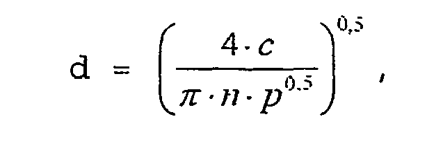
wobei ![]()
ist. n bezeichnet die Anzahl der Abspritzöffnungen 7 und beträgt mindestens 2, p ist der in der Brennstoffverteilerleitung anliegende Brennstoffdruck in Mpa.The diameter d of the
in which ![]()
is. n denotes the number of
Die Abspritzöffnungen 7 können an beliebigen Stellen des Ventilsitzkörpers 5 angebracht sein. Die Konfiguration der Abspritzöffnungen 7 kann aus einem oder mehreren runden oder elliptischen, konzentrisch oder exzentrisch zueinander oder zu einem Mittelpunkt des Ventilsitzkörpers 5 angeordneten Lochkreisen oder aus einer oder mehreren parallel, schräg, versetzt oder nicht versetzt zueinander angeordneten geraden oder gebogenen Lochreihen bestehen.The
Ein Abstand zwischen Mittelpunkten der Abspritzöffnungen 7 kann äquidistant oder unterschiedlich sein, sollte jedoch aus fertigungstechnischen Gründen mindestens 180% des Durchmessers d der Abspritzöffnungen 7 betragen. Die räumliche Orientierung einer Längsachse der Abspritzöffnungen 7 kann für jede Abspritzöffnung 7 verschieden sein. Keine der Längsachsen ist jedoch auf eine nicht weiter dargestellte, ebenfalls im Brennraum der Brennkraftmaschine angeordnete Zündkerze gerichtet. Dadurch kann eine verkürzte Lebensdauer der Zündkerze vermieden werden.A distance between centers of the
Die Gesamtheit aller Abspritzöffnungen 7 spritzt eine Gemischwolke in den Brennraum ein, deren Schwerpunktsachse in beliebiger räumlicher Richtung gegenüber einer Längsachse 37 des Brennstoffeinspritzventils 1 zwischen 0° und 70° geneigt sein kann und deren kegelförmige Aufweitung zwischen 30° und 100° liegt.The entirety of all
Die Wandstärke t des Ventilsitzkörpers 5 berechnet sich dabei wie folgt: ![]()
mit ![]()
und dem Brennstoffdruck p in der Brennstoffverteilerleitung in Mpa.The wall thickness t of the ![]()
With ![]()
and the fuel pressure p in the fuel rail in Mpa.
Entsprechend der Wandstärke t ergibt sich mit der jeweiligen Neigung der Abspritzöffnungen 7 die Gesamtlänge 1 und die reduzierte Länge 1' der Abspritzöffnungen 7. Der Ventilsitzkörper 5 kann in einfacher Weise in den entsprechenden Bereichen bearbeitet werden.Corresponding to the wall thickness t, the overall length 1 and the reduced length 1 'of the spray-
Die Erfindung ist nicht auf das dargestellte Ausführungsbeispiel beschränkt und z. B. für beliebig angeordnete Abspritzöffnungen 7 sowie für beliebige Bauweisen von nach innen öffnenden Mehrloch-Brennstoffeinspritzventilen 1 anwendbar, gemäß folgenden Ansprüchen.The invention is not limited to the illustrated embodiment and z. B. for arbitrarily arranged
Claims (11)
- Method for operating a fuel injection valve (1) for directly injecting fuel into a combustion chamber (39) of an internal combustion engine, having an excitable actuator (10), having a valve needle (3), which is operatively connected to the actuator (10) and which is acted on in a closing direction by a restoring spring (23), for actuating a valve closing body (4) which forms a sealing seat together with a valve seat surface (6) which is formed on a valve seat body (5), and having a number n of at least n = 2 ejection openings (7), with the ejection openings (7) widening into a widened portion (38) in an ejection direction of the fuel,
characterized
in that the pressure p of the fuel flowing through the fuel injection valve (1) is greater than 10 bar, with a wall thickness t of the valve seat body (5) amounting to t ≥ k*p0.5 [mm], where k = 0.06 mm/Mpa0.5 and p, in Mpa, is the fuel pressure prevailing in the fuel distribution line,
in that the ratio of a total length 1 of the ejection openings (7) to a smallest diameter d of the ejection openings amounts to 1 s 3*d,
in that a reduced length 1' of the ejection openings (7) at the inflow side of the widened portion (38) amounts to 1' ≤ 3 · d, where d is the smallest diameter of the ejection opening and where the diameter d amounts to
where c is a constant, and
in that the value of c lies in the range 0.3 ≤ c ≤ 0.6 [mm2 Mpa0.5]. - Method according to Claim 1,
characterized
in that the ejection openings (7) are arranged on one or more round or elliptical hole circles which are arranged concentrically or eccentrically with respect to one another or with respect to a central point of the valve seat body (5). - Method according to Claim 1 or 2,
characterized
in that the ejection openings (7) are arranged in one or more straight or curved hole rows which are arranged in parallel with one another, obliquely with respect to one another or so as to be offset or not offset with respect to one another. - Method according to one of Claims 1 to 3,
characterized
in that a spacing between central points of two adjacent ejection openings (7) is equidistant. - Method according to Claim 4,
characterized
in that the spacing between the central points of two adjacent ejection openings (7) amounts to at least 180% of the diameter (d) of the ejection openings (7). - Method according to one of Claims 1 to 5,
characterized
in that a spatial orientation of a longitudinal axis is different for each ejection opening (7). - Method according to one of Claims 1 to 6,
characterized
in that each ejection opening (7) opens out into a separate widened portion (38). - Method according to one of Claims 1 to 6,
characterized
in that the widened portions (38) of a plurality of ejection openings (7) are connected to one another. - Method according to Claim 8,
characterized
in that the widened portions (38) are arranged on one or more round or elliptical hole circles which are arranged concentrically or eccentrically with respect to one another or with respect to a central point of the valve seat body (5). - Method according to Claim 8,
characterized
in that the widened portions (38) are arranged in one or more straight or curved hole rows which are arranged in parallel with one another, obliquely with respect to one another or so as to be offset or not offset with respect to one another. - Method according to one of Claims 1 to 10,
characterized
none of the longitudinal axes of the ejection openings in that (7) is directed towards a spark plug which is arranged in the combustion chamber of the internal combustion engine.
Applications Claiming Priority (3)
| Application Number | Priority Date | Filing Date | Title |
|---|---|---|---|
| DE10307931 | 2003-02-25 | ||
| DE10307931A DE10307931A1 (en) | 2003-02-25 | 2003-02-25 | Fuel injector |
| PCT/DE2003/003841 WO2004076851A1 (en) | 2003-02-25 | 2003-11-19 | Fuel injection valve |
Publications (2)
| Publication Number | Publication Date |
|---|---|
| EP1599669A1 EP1599669A1 (en) | 2005-11-30 |
| EP1599669B1 true EP1599669B1 (en) | 2009-10-14 |
Family
ID=32920611
Family Applications (1)
| Application Number | Title | Priority Date | Filing Date |
|---|---|---|---|
| EP03767438A Expired - Lifetime EP1599669B1 (en) | 2003-02-25 | 2003-11-19 | Fuel injection valve |
Country Status (5)
| Country | Link |
|---|---|
| US (1) | US7677478B2 (en) |
| EP (1) | EP1599669B1 (en) |
| JP (1) | JP4200137B2 (en) |
| DE (2) | DE10307931A1 (en) |
| WO (1) | WO2004076851A1 (en) |
Families Citing this family (24)
| Publication number | Priority date | Publication date | Assignee | Title |
|---|---|---|---|---|
| DE10319694A1 (en) * | 2003-05-02 | 2004-12-02 | Robert Bosch Gmbh | Fuel injector |
| DE10354467A1 (en) * | 2003-11-21 | 2005-06-09 | Robert Bosch Gmbh | Fuel injector |
| FR2878583A1 (en) * | 2004-11-29 | 2006-06-02 | Renault Sas | Fuel injector nozzle for e.g. direct injection diesel engine of motor vehicle, has injection conduit with inner cylindrical wall against which liquid fuel boundary layer reseals, after passage of bump formed by convex portions |
| JP2007177766A (en) * | 2005-12-28 | 2007-07-12 | Toyota Motor Corp | Fuel injection device |
| JP4610631B2 (en) * | 2008-05-01 | 2011-01-12 | 三菱電機株式会社 | Fuel injection valve |
| JP4988791B2 (en) * | 2009-06-18 | 2012-08-01 | 日立オートモティブシステムズ株式会社 | Fuel injection valve |
| US20110030635A1 (en) * | 2009-08-04 | 2011-02-10 | International Engine Intellectual Property Company, Llc | Fuel injector nozzle for reduced coking |
| JP5395007B2 (en) * | 2010-07-22 | 2014-01-22 | 日立オートモティブシステムズ株式会社 | Fuel injection valve and vehicle internal combustion engine equipped with the same |
| KR101198805B1 (en) * | 2010-12-02 | 2012-11-07 | 현대자동차주식회사 | Injector for vehicle |
| FR2968720B1 (en) * | 2010-12-09 | 2015-08-07 | Continental Automotive France | INJECTOR, IN PARTICULAR FOR THE MULTIPOINT INJECTION OF FUEL IN AN INTERNAL COMBUSTION ENGINE |
| DE102011089240A1 (en) * | 2011-12-20 | 2013-06-20 | Robert Bosch Gmbh | Fuel injection valve and method for forming injection openings |
| JP5959892B2 (en) * | 2012-03-26 | 2016-08-02 | 日立オートモティブシステムズ株式会社 | Spark ignition type fuel injection valve |
| DE102012209326A1 (en) * | 2012-06-01 | 2013-12-05 | Robert Bosch Gmbh | Fuel injector |
| DE102012221713A1 (en) * | 2012-11-28 | 2014-05-28 | Robert Bosch Gmbh | Injector |
| KR101337713B1 (en) * | 2012-12-20 | 2013-12-06 | 주식회사 현대케피코 | Vehicular gdi injector with valve seat body for fuel atomization |
| US9850869B2 (en) * | 2013-07-22 | 2017-12-26 | Delphi Technologies, Inc. | Fuel injector |
| JP6364962B2 (en) * | 2014-05-28 | 2018-08-01 | 株式会社デンソー | Fuel injection valve |
| JP6311472B2 (en) * | 2014-06-16 | 2018-04-18 | 株式会社デンソー | Fuel injection valve |
| JP5969564B2 (en) * | 2014-10-01 | 2016-08-17 | トヨタ自動車株式会社 | Fuel injection valve |
| JP6292188B2 (en) * | 2015-04-09 | 2018-03-14 | 株式会社デンソー | Fuel injection device |
| US10995655B2 (en) * | 2016-11-30 | 2021-05-04 | Hitachi Automotive Systems, Ltd. | Fuel injection device |
| US10865754B2 (en) * | 2017-04-05 | 2020-12-15 | Progress Rail Services Corporation | Fuel injector having needle tip and nozzle body surfaces structured for reduced sac volume and fracture resistance |
| US10612508B2 (en) * | 2017-06-28 | 2020-04-07 | Caterpillar Inc. | Fuel injector for internal combustion engines |
| NO20171100A1 (en) | 2017-07-04 | 2019-01-07 | Rsm Imagineering As | A dual-acting pressure boosting liquid partition device, system, fleet and use |
Citations (1)
| Publication number | Priority date | Publication date | Assignee | Title |
|---|---|---|---|---|
| US20020144671A1 (en) * | 1998-06-22 | 2002-10-10 | Hitachi, Ltd. | Cylinder injection type internal combustion engine, control method for internal combustion engine, and fuel injection valve |
Family Cites Families (13)
| Publication number | Priority date | Publication date | Assignee | Title |
|---|---|---|---|---|
| US4657189A (en) * | 1985-03-13 | 1987-04-14 | Aisan Kogyo Kabushiki Kaisha | Electromagnetic fuel injection valve for an internal combustion engine having a plurality of intake valves |
| JP2819702B2 (en) * | 1989-12-12 | 1998-11-05 | 株式会社デンソー | Fuel injection valve |
| JPH09177589A (en) * | 1995-12-27 | 1997-07-08 | Mitsubishi Electric Corp | In-cylinder injection type fuel controller of internal combustion engine |
| DE19625059A1 (en) | 1996-06-22 | 1998-01-02 | Bosch Gmbh Robert | Injection valve, in particular for injecting fuel directly into a combustion chamber of an internal combustion engine |
| JP3343672B2 (en) | 1997-08-18 | 2002-11-11 | 愛三工業株式会社 | Fuel injection valve |
| JPH11117833A (en) | 1997-10-13 | 1999-04-27 | Honda Motor Co Ltd | Fuel injection nozzle and manufacture thereof |
| DE19815918A1 (en) | 1998-04-09 | 1999-10-21 | Man B & W Diesel As | Fuel injector |
| DE19838771A1 (en) | 1998-08-26 | 2000-03-02 | Man B & W Diesel Ag | Injection nozzle for internal combustion engine, particularly diesel engine, has at least one spray hole in surface adjacent to combustion chamber for feeding fuel |
| JP2000145590A (en) | 1998-11-10 | 2000-05-26 | Aisan Ind Co Ltd | Fuel injection valve |
| DE19854828A1 (en) | 1998-11-27 | 2000-05-31 | Bosch Gmbh Robert | Fuel injection nozzle for self-igniting internal combustion engines |
| JP2001165017A (en) | 1998-12-14 | 2001-06-19 | Denso Corp | Fuel injection nozzle |
| DE10118163B4 (en) * | 2001-04-11 | 2007-04-19 | Robert Bosch Gmbh | Fuel injector |
| DE10122350B4 (en) | 2001-05-09 | 2006-09-07 | Robert Bosch Gmbh | fuel injection system |
-
2003
- 2003-02-25 DE DE10307931A patent/DE10307931A1/en not_active Withdrawn
- 2003-11-19 US US10/545,514 patent/US7677478B2/en not_active Expired - Fee Related
- 2003-11-19 JP JP2004568638A patent/JP4200137B2/en not_active Expired - Fee Related
- 2003-11-19 WO PCT/DE2003/003841 patent/WO2004076851A1/en active Application Filing
- 2003-11-19 EP EP03767438A patent/EP1599669B1/en not_active Expired - Lifetime
- 2003-11-19 DE DE50312036T patent/DE50312036D1/en not_active Expired - Lifetime
Patent Citations (1)
| Publication number | Priority date | Publication date | Assignee | Title |
|---|---|---|---|---|
| US20020144671A1 (en) * | 1998-06-22 | 2002-10-10 | Hitachi, Ltd. | Cylinder injection type internal combustion engine, control method for internal combustion engine, and fuel injection valve |
Also Published As
| Publication number | Publication date |
|---|---|
| JP4200137B2 (en) | 2008-12-24 |
| JP2006509157A (en) | 2006-03-16 |
| DE50312036D1 (en) | 2009-11-26 |
| WO2004076851A1 (en) | 2004-09-10 |
| US7677478B2 (en) | 2010-03-16 |
| US20070012805A1 (en) | 2007-01-18 |
| DE10307931A1 (en) | 2004-10-28 |
| EP1599669A1 (en) | 2005-11-30 |
Similar Documents
| Publication | Publication Date | Title |
|---|---|---|
| EP1599669B1 (en) | Fuel injection valve | |
| EP1379773B1 (en) | Fuel injection valve | |
| EP1339975B1 (en) | Fuel injection valve | |
| EP1623109B1 (en) | Fuel injection valve | |
| WO2002012711A1 (en) | Fuel injection valve | |
| EP1379778B1 (en) | Fuel injection valve | |
| EP2521853B1 (en) | Fuel injection valve | |
| EP1395749B1 (en) | Fuel injection valve | |
| EP1474604B1 (en) | Fuel injection valve | |
| EP1312796B1 (en) | Fuel injection valve | |
| EP1633973B1 (en) | Fuel injection valve | |
| EP1327066B1 (en) | Fuel injection valve | |
| DE10354467A1 (en) | Fuel injector | |
| DE10050751A1 (en) | Fuel injection valve for IC engines has swirl-generating device formed by swirl channels in upstream side of valve seat body | |
| EP2925998B1 (en) | Injection valve | |
| EP1702156B1 (en) | Fuel injection valve | |
| DE10049519B4 (en) | Fuel injector | |
| EP1598550B1 (en) | Fuel injector | |
| EP1260703B1 (en) | Fuel injection valve | |
| DE102005024067A1 (en) | Fuel injection valve for internal combustion engines has an excitable actuator for operating a valve-closing body to form a sealed seating with a valve-seating surface | |
| EP1559906A2 (en) | Fuel injection valve | |
| DE10331805A1 (en) | Fuel injection valve for internal combustion engines with magnetic coil co-acting with valve needle with resetting spring acting in stop direction | |
| DE10304866A1 (en) | Motor vehicle internal combustion engine fuel injection valve has injection openings formed in valve seat with radial seating extending above them | |
| DE10342773A1 (en) | Fuel injecting valve for internal combustion engine, has vacuum sealed seat with seat surface, where angle of vacuum sealed seat is of specified degree and hose down opening is arranged such that opening is in downstream side of seat |
Legal Events
| Date | Code | Title | Description |
|---|---|---|---|
| PUAI | Public reference made under article 153(3) epc to a published international application that has entered the european phase |
Free format text: ORIGINAL CODE: 0009012 |
|
| 17P | Request for examination filed |
Effective date: 20050926 |
|
| AK | Designated contracting states |
Kind code of ref document: A1 Designated state(s): AT BE BG CH CY CZ DE DK EE ES FI FR GB GR HU IE IT LI LU MC NL PT RO SE SI SK TR |
|
| RBV | Designated contracting states (corrected) |
Designated state(s): DE FR GB IT |
|
| 17Q | First examination report despatched |
Effective date: 20051223 |
|
| GRAP | Despatch of communication of intention to grant a patent |
Free format text: ORIGINAL CODE: EPIDOSNIGR1 |
|
| GRAS | Grant fee paid |
Free format text: ORIGINAL CODE: EPIDOSNIGR3 |
|
| GRAA | (expected) grant |
Free format text: ORIGINAL CODE: 0009210 |
|
| AK | Designated contracting states |
Kind code of ref document: B1 Designated state(s): DE FR GB IT |
|
| REG | Reference to a national code |
Ref country code: GB Ref legal event code: FG4D Free format text: NOT ENGLISH |
|
| REF | Corresponds to: |
Ref document number: 50312036 Country of ref document: DE Date of ref document: 20091126 Kind code of ref document: P |
|
| PGFP | Annual fee paid to national office [announced via postgrant information from national office to epo] |
Ref country code: FR Payment date: 20100105 Year of fee payment: 7 Ref country code: GB Payment date: 20091221 Year of fee payment: 7 |
|
| PGFP | Annual fee paid to national office [announced via postgrant information from national office to epo] |
Ref country code: IT Payment date: 20091224 Year of fee payment: 7 |
|
| PGFP | Annual fee paid to national office [announced via postgrant information from national office to epo] |
Ref country code: DE Payment date: 20100121 Year of fee payment: 7 |
|
| PLBE | No opposition filed within time limit |
Free format text: ORIGINAL CODE: 0009261 |
|
| STAA | Information on the status of an ep patent application or granted ep patent |
Free format text: STATUS: NO OPPOSITION FILED WITHIN TIME LIMIT |
|
| 26N | No opposition filed |
Effective date: 20100715 |
|
| GBPC | Gb: european patent ceased through non-payment of renewal fee |
Effective date: 20101119 |
|
| REG | Reference to a national code |
Ref country code: FR Ref legal event code: ST Effective date: 20110801 |
|
| REG | Reference to a national code |
Ref country code: DE Ref legal event code: R119 Ref document number: 50312036 Country of ref document: DE Effective date: 20110601 Ref country code: DE Ref legal event code: R119 Ref document number: 50312036 Country of ref document: DE Effective date: 20110531 |
|
| PG25 | Lapsed in a contracting state [announced via postgrant information from national office to epo] |
Ref country code: FR Free format text: LAPSE BECAUSE OF NON-PAYMENT OF DUE FEES Effective date: 20101130 |
|
| PG25 | Lapsed in a contracting state [announced via postgrant information from national office to epo] |
Ref country code: GB Free format text: LAPSE BECAUSE OF NON-PAYMENT OF DUE FEES Effective date: 20101119 |
|
| PG25 | Lapsed in a contracting state [announced via postgrant information from national office to epo] |
Ref country code: IT Free format text: LAPSE BECAUSE OF NON-PAYMENT OF DUE FEES Effective date: 20101119 |
|
| PG25 | Lapsed in a contracting state [announced via postgrant information from national office to epo] |
Ref country code: DE Free format text: LAPSE BECAUSE OF NON-PAYMENT OF DUE FEES Effective date: 20110531 |