EP1599668B1 - Dispositif d'injection de carburant pour un moteur a combustion interne - Google Patents
Dispositif d'injection de carburant pour un moteur a combustion interne Download PDFInfo
- Publication number
- EP1599668B1 EP1599668B1 EP03773513A EP03773513A EP1599668B1 EP 1599668 B1 EP1599668 B1 EP 1599668B1 EP 03773513 A EP03773513 A EP 03773513A EP 03773513 A EP03773513 A EP 03773513A EP 1599668 B1 EP1599668 B1 EP 1599668B1
- Authority
- EP
- European Patent Office
- Prior art keywords
- pump
- interior
- fuel
- injection device
- fuel injection
- Prior art date
- Legal status (The legal status is an assumption and is not a legal conclusion. Google has not performed a legal analysis and makes no representation as to the accuracy of the status listed.)
- Expired - Lifetime
Links
- 239000000446 fuel Substances 0.000 title claims description 53
- 238000002347 injection Methods 0.000 title claims description 21
- 239000007924 injection Substances 0.000 title claims description 21
- 238000002485 combustion reaction Methods 0.000 title claims description 10
- 230000006698 induction Effects 0.000 claims 4
- 238000011144 upstream manufacturing Methods 0.000 claims 1
- 239000002828 fuel tank Substances 0.000 description 5
- 230000006835 compression Effects 0.000 description 1
- 238000007906 compression Methods 0.000 description 1
- 238000001816 cooling Methods 0.000 description 1
- 230000001419 dependent effect Effects 0.000 description 1
- 238000011161 development Methods 0.000 description 1
- 230000018109 developmental process Effects 0.000 description 1
- 238000005461 lubrication Methods 0.000 description 1
Images
Classifications
-
- F—MECHANICAL ENGINEERING; LIGHTING; HEATING; WEAPONS; BLASTING
- F02—COMBUSTION ENGINES; HOT-GAS OR COMBUSTION-PRODUCT ENGINE PLANTS
- F02M—SUPPLYING COMBUSTION ENGINES IN GENERAL WITH COMBUSTIBLE MIXTURES OR CONSTITUENTS THEREOF
- F02M59/00—Pumps specially adapted for fuel-injection and not provided for in groups F02M39/00 -F02M57/00, e.g. rotary cylinder-block type of pumps
- F02M59/02—Pumps specially adapted for fuel-injection and not provided for in groups F02M39/00 -F02M57/00, e.g. rotary cylinder-block type of pumps of reciprocating-piston or reciprocating-cylinder type
- F02M59/10—Pumps specially adapted for fuel-injection and not provided for in groups F02M39/00 -F02M57/00, e.g. rotary cylinder-block type of pumps of reciprocating-piston or reciprocating-cylinder type characterised by the piston-drive
- F02M59/102—Mechanical drive, e.g. tappets or cams
-
- F—MECHANICAL ENGINEERING; LIGHTING; HEATING; WEAPONS; BLASTING
- F02—COMBUSTION ENGINES; HOT-GAS OR COMBUSTION-PRODUCT ENGINE PLANTS
- F02M—SUPPLYING COMBUSTION ENGINES IN GENERAL WITH COMBUSTIBLE MIXTURES OR CONSTITUENTS THEREOF
- F02M59/00—Pumps specially adapted for fuel-injection and not provided for in groups F02M39/00 -F02M57/00, e.g. rotary cylinder-block type of pumps
- F02M59/02—Pumps specially adapted for fuel-injection and not provided for in groups F02M39/00 -F02M57/00, e.g. rotary cylinder-block type of pumps of reciprocating-piston or reciprocating-cylinder type
- F02M59/08—Pumps specially adapted for fuel-injection and not provided for in groups F02M39/00 -F02M57/00, e.g. rotary cylinder-block type of pumps of reciprocating-piston or reciprocating-cylinder type characterised by two or more pumping elements with conjoint outlet or several pumping elements feeding one engine cylinder
-
- F—MECHANICAL ENGINEERING; LIGHTING; HEATING; WEAPONS; BLASTING
- F02—COMBUSTION ENGINES; HOT-GAS OR COMBUSTION-PRODUCT ENGINE PLANTS
- F02M—SUPPLYING COMBUSTION ENGINES IN GENERAL WITH COMBUSTIBLE MIXTURES OR CONSTITUENTS THEREOF
- F02M63/00—Other fuel-injection apparatus having pertinent characteristics not provided for in groups F02M39/00 - F02M57/00 or F02M67/00; Details, component parts, or accessories of fuel-injection apparatus, not provided for in, or of interest apart from, the apparatus of groups F02M39/00 - F02M61/00 or F02M67/00; Combination of fuel pump with other devices, e.g. lubricating oil pump
- F02M63/0001—Fuel-injection apparatus with specially arranged lubricating system, e.g. by fuel oil
-
- F—MECHANICAL ENGINEERING; LIGHTING; HEATING; WEAPONS; BLASTING
- F02—COMBUSTION ENGINES; HOT-GAS OR COMBUSTION-PRODUCT ENGINE PLANTS
- F02M—SUPPLYING COMBUSTION ENGINES IN GENERAL WITH COMBUSTIBLE MIXTURES OR CONSTITUENTS THEREOF
- F02M63/00—Other fuel-injection apparatus having pertinent characteristics not provided for in groups F02M39/00 - F02M57/00 or F02M67/00; Details, component parts, or accessories of fuel-injection apparatus, not provided for in, or of interest apart from, the apparatus of groups F02M39/00 - F02M61/00 or F02M67/00; Combination of fuel pump with other devices, e.g. lubricating oil pump
- F02M63/02—Fuel-injection apparatus having several injectors fed by a common pumping element, or having several pumping elements feeding a common injector; Fuel-injection apparatus having provisions for cutting-out pumps, pumping elements, or injectors; Fuel-injection apparatus having provisions for variably interconnecting pumping elements and injectors alternatively
- F02M63/0225—Fuel-injection apparatus having a common rail feeding several injectors ; Means for varying pressure in common rails; Pumps feeding common rails
Definitions
- the invention relates to a fuel injection device for an internal combustion engine according to the preamble of claim 1.
- Such a fuel injector is known from WO 01/40656 A.
- This fuel injection device has a high-pressure pump, is conveyed by the fuel in a memory, is taken from the fuel for injection to the internal combustion engine.
- a delivery pump is provided, is conveyed by the fuel from a fuel tank to the high pressure pump.
- the high-pressure pump has a housing and at least one pump element which is driven by a drive arranged in an interior of the housing.
- the pump element has a pump piston driven by the drive in a lifting movement, which limits a pump working space. During a suction stroke of the pump piston, the latter sucks fuel into the pump working chamber via an inlet and during a delivery stroke of the pump piston it displaces fuel from the pump working chamber via a drain.
- the pump piston moves in its suction stroke into the interior of the housing and during its delivery stroke out of the interior.
- the feed pump can be driven electrically or mechanically. In order to generate a sufficiently high pressure while a powerful and correspondingly expensive drive for the feed pump is required. Alternatively, a feed pump with low power electric drive and In addition, a feed pump can be combined with mechanical drive, which is also expensive.
- the fuel injection device with the features of claim 1 has the advantage that the high-pressure pump at the same time forms a feed pump through which the sucked at their suction strokes fuel is promoted.
- the feed pump is conveyed by the fuel from the fuel tank into the interior of the housing of the high-pressure pump, it can be designed with low power and correspondingly inexpensive.
- the embodiment according to claim 2 allows continuous operation of the feed pump, in that it can flow discharged from this with closed check valve fuel in the discharge area.
- the embodiment of claim 6 allows a flow rate that is greater than the required suction amount of the pump element and thus also an overflow, by which the drive in the interior of the housing can be lubricated and cooled.
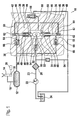
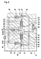
- FIG. 1 shows a fuel injection device for an internal combustion engine in a schematic representation with a high-pressure pump at the end of the delivery stroke of the pump elements and Figure 2, the high-pressure pump at the end of the suction stroke of the pump elements.
- FIG. 1 shows a fuel injection device of an internal combustion engine, for example of a motor vehicle, which has a high-pressure pump 10.
- a high-pressure pump 10 By the high pressure pump 10 while fuel is conveyed under high pressure in a memory 12, is taken from the fuel for injection to the internal combustion engine.
- an injector 14 At each cylinder of the internal combustion engine, an injector 14 is arranged, which is connected via a line 16 to the memory 12.
- the injector 14 has a control valve 18, which is controlled by an electronic control device 20, and by which the opening of the injector 14 and thus the fuel injection is controlled.
- a feed pump 22 fuel is conveyed from a fuel tank 24 to the high-pressure pump 10.
- the feed pump 22 preferably has an electric drive, but may also be driven mechanically.
- a filter 26 is arranged to filter the funded by the high pressure pump 10 fuel.
- the high-pressure pump 10 has a housing 30 in which an input shaft 32 is rotatably mounted about an axis 33 in an inner space 31.
- the drive shaft 32 is driven for example by the internal combustion engine.
- the drive shaft 32 has in the interior 31 at least one cam 34, wherein in the illustrated embodiment, a double cam is provided which has two diametrically opposed cam lobes.
- the high-pressure pump 10 has at least one pump element 36 arranged in the housing 30, with two diametrically opposite pump elements 36 being provided in the exemplary embodiment shown.
- each Pump element 36 has a pump piston 38 which is tightly guided in a cylinder bore 40 extending at least approximately radially to the axis of rotation 33 of the drive shaft 32 and defines a pump working space 42 in this with its outwardly facing end face.
- the cylinder bore 40 may be formed directly in the housing 30 or in an inserted into the housing 30 insert.
- the pump piston 38 protrudes with its radially inwardly facing end of the cylinder bore 40 and is supported via a plunger 44 on the cam 34 of the drive shaft 30 from.
- the plunger 44 is guided tightly in a bore 46 in the housing 30 and preferably has a larger diameter than the pump piston 38 in its the pump working space 42 bounding area.
- the pump piston 38 has at its piston foot 39, with which it is supported on the plunger 44, a larger diameter than in its the pump working space 42 limiting range and an approximately equal diameter as the plunger 44.
- a prestressed spring 48 for example in the form of a helical compression spring, clamped by the pump piston 38 and the piston foot 39 of the plunger 44 is held in contact with the cam 34 of the drive shaft 32.
- a cylindrical roller 50 is inserted, which rolls on the cam 34.
- the plunger 44 limited with its the pump piston 38 facing away from the bore 46 and protruding part of the interior 31 of the housing 30.
- the plunger 44 may also be omitted, in which then the pump piston 38 via its piston foot 39, in which, for example, a roller 50 may be arranged can, directly on the cam 34 is supported.
- the funded by the feed pump 22 fuel is supplied via a line 23 to the interior 31 of the housing 30 of the high-pressure pump 10.
- a check valve 52 opening towards the interior 31 is arranged, this prevents fuel from the interior 31 to the feed pump 22 can flow back.
- a line 54 from a discharge area, which may be, for example, a return 55 to the fuel tank 24.
- a line 56 leads to a discharge area, which in turn may be the return 55 to the fuel tank 24.
- a pressure valve 58 is arranged, which releases the connection to the return 55 only when a predetermined pressure in the interior 31 is exceeded and at lower pressure, the connection to the return line 55 keeps closed.
- an inlet 60 opens into the pump working chamber 42 of the pump elements 36, in which a non-return valve 62 opening into the pump working chamber 42 is arranged as an inlet valve. From the pump working chamber 42 also leads in each case from a drain 64, which opens into the memory 12 and in which a from the pump working chamber 42 to the memory 12 out opening check valve 66 is arranged as an outlet valve.
- the inlet 60 of the pump working spaces 42 of the pump elements 36 is in each case connected to the interior 31 of the housing 30 of the high-pressure pump 10.
- the pump pistons 38 of the pump elements 36 promote synchronously with each other, that is, these simultaneously perform their respective delivery stroke and their respective suction stroke.
- the check valve 52 thereby opens and funded by the feed pump 22 fuel flows into the interior 31 and fills it.
- the feed pump 22 continuously delivers fuel and the fuel delivered by the feed pump 22 when the check valve 52 is closed flows via the line 54 into the return 55.
- the plunger 44 Since the plunger 44 has a larger diameter than the pump piston 38 in their respective pump working space 42 limiting area 38 more fuel from the interior 31 is displaced by this during the suction stroke of the pump piston as sucked by the pump piston 38 into the pump work chambers 42.
- the excess amount of fuel flows with open pressure valve 58 via the line 56 in the return line 55. This is a constant emptying and filling of the interior 31 with fuel achieved and thus good lubrication and cooling of the drive of the high-pressure pump 10, in particular the drive shaft 32, and the Plunger 44 and running on the cam 34 rollers 50.
- the feed pump 22 only needs to generate a relatively low pressure in order to fill the interior 31 with fuel can.
- the plungers 44 have approximately the same diameter as the pump pistons 38 in their respective pump working space 42 limiting range, so that a correspondingly smaller amount of fuel is conveyed by the plunger 44.
- FIG. 1 shows the high-pressure pump 10 at the end of the delivery stroke of the pump piston 38, in which the pump pistons 38 are in the region of their outer dead center.
- the plunger 44 are immersed furthest in the holes 46 and the volume of the interior 31 is the largest.
- the intake valves 62 are closed, the exhaust valves 66 are opened and the check valve 52 is opened, so that fuel is conveyed by the feed pump 22 into the inner space 31.
- the high-pressure pump 10 is shown at the end of the suction stroke of the pump piston 38, in which the pump piston 38 are in the region of its inner dead center.
- the plungers 44 are immersed furthest out of the holes 46 in the interior 31, so that the volume of the interior 31 is the smallest.
- the intake valves 62 are opened, the exhaust valves 66 and the check valve 52 are closed.
Claims (10)
- Dispositif d'injection de carburant pour un moteur à combustion interne, comprenant :- une pompe haute pression (10) permettant d'acheminer du carburant dans un accumulateur (12), à partir duquel le carburant est prélevé pour être injecté au niveau du moteur à combustion interne,- une pompe d'alimentation (22) permettant d'acheminer le carburant depuis un réservoir de stockage de carburant (24) jusqu'à la pompe haute pression (10),la pompe haute pression (10) présentant un boîtier (30) avec un espace intérieur (31) dans lequel est disposé un entraînement (32, 34) pour au moins un élément de pompe (36) de la pompe haute pression (10), l'élément de pompe (36) présentant un piston de pompe (38) entraîné par l'entraînement (32, 34) dans un mouvement de course et qui délimite une chambre de travail de la pompe (42) dans laquelle est acheminé du carburant par une arrivée (60) lors d'une course d'admission du piston de pompe (38) et hors de laquelle, du carburant est refoulé par une évacuation (64) jusque dans l'accumulateur (12) lors d'une course de refoulement du piston de pompe (38),
le piston de pompe (38) se déplaçant, lors de sa course d'admission, vers l'espace intérieur (31) et lors de sa course de refoulement, en s'éloignant de l'espace intérieur (31),
caractérisé en ce que
la pompe d'alimentation (22) achemine le carburant dans l'espace intérieur (31) par une liaison (23) présentant un clapet anti-retour (52) s'ouvrant vers l'espace intérieur (31) du boîtier (30) et l'arrivée (60) de la chambre de travail de la pompe (42) est reliée à l'espace intérieur (31) de telle sorte que lors d'une course d'admission du piston de pompe (38), dans son mouvement orienté vers l'espace intérieur (31), le carburant refoulé hors de l'espace intérieur (31) est admis dans la chambre de travail de la pompe (42). - Dispositif d'injection de carburant selon la revendication 1,
caractérisé en ce qu'
avant la liaison (23) entre la pompe d'alimentation (22) et l'espace intérieur (31) du boîtier (30), en amont du clapet anti-retour (52), une liaison (54) part vers une zone de détente (55). - Dispositif d'injection de carburant selon la revendication 1 ou 2,
caractérisé en ce que
le piston de pompe (38) est sollicité dans la direction de sa course d'admission par un ressort précontraint (48). - Dispositif d'injection de carburant selon l'une des revendications 1 à 3,
caractérisé en ce que
l'entraînement présente un arbre d'entraînement (32) comprenant au moins une came (34) provoquant le mouvement de course du piston de pompe (38). - Dispositif d'injection de carburant selon l'une des revendications là 4,
caractérisé en ce que
le piston de pompe (38) s'appuie par un poussoir (44) contre l'entraînement (32, 34), il est guidé de façon étanche dans un alésage (46) du boîtier (30) et délimite partiellement l'espace intérieur (31). - Dispositif d'injection de carburant selon la revendication 5,
caractérisé en ce que
le poussoir (44) présente un diamètre supérieur au piston de pompe (38) dans sa zone délimitant la chambre de travail de la pompe (42). - Dispositif d'injection de carburant selon l'une des revendications 4 à 6,
caractérisé par
une came multiple (34). - Dispositif d'injection de carburant selon l'une des revendications précédentes,
caractérisé en ce que
dans l'arrivée (60) de la chambre de travail de la pompe (42) est disposé un clapet anti-retour (62) s'ouvrant vers la chambre de travail de la pompe (42). - Dispositif d'injection de carburant selon l'une des revendications précédentes,
caractérisé en ce que
la pompe haute pression (10) présente plusieurs éléments de pompe (36). - Dispositif d'injection de carburant selon l'une des revendications précédentes,
caractérisé en ce qu'
à partir de l'espace intérieur (31) du boîtier (30), une liaison (56) part vers une zone de détente (55) dans laquelle est disposée une soupape de compression (58) qui ouvre la liaison (54) lorsque l'on dépasse une pression prédéterminée dans l'espace intérieur (31).
Applications Claiming Priority (3)
| Application Number | Priority Date | Filing Date | Title |
|---|---|---|---|
| DE10307877 | 2003-02-25 | ||
| DE10307877A DE10307877A1 (de) | 2003-02-25 | 2003-02-25 | Kraftstoffeinspritzeinrichtung für eine Brennkraftmaschine |
| PCT/DE2003/003394 WO2004076847A1 (fr) | 2003-02-25 | 2003-10-13 | Dispositif d'injection de carburant pour un moteur a combustion interne |
Publications (2)
| Publication Number | Publication Date |
|---|---|
| EP1599668A1 EP1599668A1 (fr) | 2005-11-30 |
| EP1599668B1 true EP1599668B1 (fr) | 2006-07-26 |
Family
ID=32797716
Family Applications (1)
| Application Number | Title | Priority Date | Filing Date |
|---|---|---|---|
| EP03773513A Expired - Lifetime EP1599668B1 (fr) | 2003-02-25 | 2003-10-13 | Dispositif d'injection de carburant pour un moteur a combustion interne |
Country Status (5)
| Country | Link |
|---|---|
| US (1) | US7850435B2 (fr) |
| EP (1) | EP1599668B1 (fr) |
| JP (1) | JP4461026B2 (fr) |
| DE (2) | DE10307877A1 (fr) |
| WO (1) | WO2004076847A1 (fr) |
Families Citing this family (11)
| Publication number | Priority date | Publication date | Assignee | Title |
|---|---|---|---|---|
| DE102007038519A1 (de) * | 2007-06-28 | 2009-01-02 | Robert Bosch Gmbh | Hochdruckkraftstoffpumpenanordnung, die über den Ventiltrieb einer Brennkraftmaschine angetrieben wird |
| DE102007034036A1 (de) * | 2007-07-20 | 2009-01-22 | Robert Bosch Gmbh | Kraftstoffhochdruckpumpe mit Rollenstößel |
| JP5094349B2 (ja) * | 2007-11-30 | 2012-12-12 | 株式会社日立産機システム | シリンダ装置、圧縮機およびシリンダ装置の製造方法 |
| US20100119393A1 (en) * | 2008-11-12 | 2010-05-13 | Delphi Technologies, Inc. | Hydraulic pump assembly |
| IT1395139B1 (it) * | 2009-08-06 | 2012-09-05 | Bosch Gmbh Robert | Pompa di alta pressione per alimentare combustibile ad un motore a combustione interna |
| DE102011004939A1 (de) | 2011-03-02 | 2012-09-06 | Robert Bosch Gmbh | Kraftstofffördereinrichtung und Verfahren zum Betätigen einer Kraftstofffördereinrichtung |
| CN102979732B (zh) * | 2012-10-30 | 2015-10-28 | 无锡鸿声铝业有限公司 | 真空旋转密封泵滚珠摩擦进油结构 |
| DE102012224408A1 (de) * | 2012-12-27 | 2014-07-17 | Robert Bosch Gmbh | Kraftstoffeinspritzsystem |
| JP6040912B2 (ja) * | 2013-11-12 | 2016-12-07 | 株式会社デンソー | 高圧ポンプ |
| DE102014225982A1 (de) * | 2014-12-16 | 2016-06-16 | Robert Bosch Gmbh | Pumpe, insbesondere Kraftstoffhochdruckpumpe |
| EP3808968A1 (fr) | 2019-10-16 | 2021-04-21 | Volvo Car Corporation | Agencement de transfert de force d'un arbre à cames vers un dispositif de sortie |
Family Cites Families (11)
| Publication number | Priority date | Publication date | Assignee | Title |
|---|---|---|---|---|
| DE19531811A1 (de) * | 1995-08-30 | 1997-03-06 | Bosch Gmbh Robert | Kraftstoffeinspritzpumpe |
| EP0979353B1 (fr) * | 1998-02-27 | 2004-09-29 | Stanadyne Corporation | Pompe d'alimentation pour rampe d'alimentation en essence |
| US6694950B2 (en) * | 1999-02-17 | 2004-02-24 | Stanadyne Corporation | Hybrid control method for fuel pump using intermittent recirculation at low and high engine speeds |
| DE19926308A1 (de) | 1999-06-09 | 2000-12-21 | Bosch Gmbh Robert | Pumpenanordnung für Kraftstoff |
| DE19933567C1 (de) * | 1999-07-16 | 2001-02-01 | Siemens Ag | Einspritzsystem für eine Brennkraftmaschine |
| DE19937673A1 (de) * | 1999-08-10 | 2001-02-22 | Siemens Ag | Einspritzanlage für eine Brennkraftmaschine |
| IT1310754B1 (it) * | 1999-11-30 | 2002-02-22 | Elasis Sistema Ricerca Fiat | Sistema di valvole per il controllo della pressione di ingresso di unliquido in una pompa ad alta pressione, e relativa valvola di |
| DE10010945B4 (de) * | 2000-03-06 | 2004-07-22 | Robert Bosch Gmbh | Pumpe zur Versorgung eines Kraftstoffeinspritzsystems und einer hydraulischen Ventilsteuerung für Brennkraftmaschinen |
| US6722864B2 (en) * | 2001-12-12 | 2004-04-20 | Denso Corporation | Fuel injection pump |
| DE10200792A1 (de) * | 2002-01-11 | 2003-07-31 | Bosch Gmbh Robert | Kraftstoffpumpe für eine Brennkraftmaschine |
| EP1803933B1 (fr) * | 2005-12-27 | 2010-05-19 | C.R.F. Societa Consortile per Azioni | Pompe haute pression de carburant, avec le carter en communication avec l'arrivée de carburant |
-
2003
- 2003-02-25 DE DE10307877A patent/DE10307877A1/de not_active Withdrawn
- 2003-10-13 WO PCT/DE2003/003394 patent/WO2004076847A1/fr active IP Right Grant
- 2003-10-13 DE DE50304406T patent/DE50304406D1/de not_active Expired - Lifetime
- 2003-10-13 JP JP2004568633A patent/JP4461026B2/ja not_active Expired - Fee Related
- 2003-10-13 EP EP03773513A patent/EP1599668B1/fr not_active Expired - Lifetime
- 2003-10-13 US US10/546,655 patent/US7850435B2/en not_active Expired - Fee Related
Also Published As
| Publication number | Publication date |
|---|---|
| JP4461026B2 (ja) | 2010-05-12 |
| US7850435B2 (en) | 2010-12-14 |
| DE10307877A1 (de) | 2004-09-02 |
| US20060193736A1 (en) | 2006-08-31 |
| JP2006514202A (ja) | 2006-04-27 |
| EP1599668A1 (fr) | 2005-11-30 |
| DE50304406D1 (de) | 2006-09-07 |
| WO2004076847A1 (fr) | 2004-09-10 |
Similar Documents
| Publication | Publication Date | Title |
|---|---|---|
| EP2207955B1 (fr) | Soupape de décharge de carburant pour dispositif d'injection de carburant, et dispositif d'injection de carburant présentant une soupape de décharge de carburant | |
| EP2798191B1 (fr) | Soupape de décharge de carburant pour un injecteur de carburant et injecteur de carburant équipé d'une soupape de décharge de carburant | |
| DE10118754B4 (de) | Hochdruckpumpe | |
| WO2005111405A1 (fr) | Pompe haute pression destinee a un dispositif d'injection de carburant d'un moteur a combustion interne | |
| EP1599668B1 (fr) | Dispositif d'injection de carburant pour un moteur a combustion interne | |
| WO2005124153A1 (fr) | Pompe haute pression conçue pour un dispositif d'injection de carburant d'un moteur a combustion interne | |
| EP2795095B1 (fr) | Pompe, en particulier une pompe á carburant pour un systeme d'injection de carburant | |
| DE102008017824A1 (de) | Stößelbaugruppe für eine Hochdruckpumpe und Hochdruckpumpe | |
| EP1537334B1 (fr) | Pompe, notamment pour un systeme d'injection de carburant destine a un moteur a combustion interne | |
| EP3061967B1 (fr) | Pompe, en particulier pompe haute pression pour carburant | |
| DE102008062518B4 (de) | Hochdruckpumpe | |
| EP2134966B1 (fr) | Pompe, notamment pompe de carburant à haute pression | |
| WO2005015017A1 (fr) | Pompe haute pression pour dispositif d'injection de carburant de moteur a combustion interne | |
| EP2143946A1 (fr) | Agencement de pompe | |
| DE10355028A1 (de) | Hochdruckpumpe, insbesondere für eine Kraftstoffeinspritzeinrichtung einer Brennkraftmaschine | |
| WO2020244882A1 (fr) | Pompe, en particulier pompe à carburant haute pression | |
| WO2009013175A1 (fr) | Pompe, en particulier pompe à carburant haute pression | |
| DE10210300B4 (de) | Pumpenelement für eine Hochdruckpumpe und Hochdruckpumpe mit steuerbarer Fördermenge | |
| DE102004023962A1 (de) | Verfahren zum Ansteuern einer Kraftstoffhochdruckpumpe einer Brennkraftmaschine und Kraftstoffeinspritzsystem für eine Brennkraftmaschine | |
| DE102021209214A1 (de) | Pumpengruppe mit einer Hochdruckpumpe und einer Niederdruckpumpe | |
| EP2872778B1 (fr) | Pompe à haute pression | |
| DE102012201308A1 (de) | Hochdruckpumpe | |
| DE102022201334A1 (de) | Pumpe, insbesondere Kraftstoffhochdruckpumpe | |
| WO2013098259A1 (fr) | Pompe, en particulier pompe à carburant haute pression pour un système d'injection de carburant | |
| DE102010043404A1 (de) | Hochdruckpumpe |
Legal Events
| Date | Code | Title | Description |
|---|---|---|---|
| PUAI | Public reference made under article 153(3) epc to a published international application that has entered the european phase |
Free format text: ORIGINAL CODE: 0009012 |
|
| 17P | Request for examination filed |
Effective date: 20050926 |
|
| AK | Designated contracting states |
Kind code of ref document: A1 Designated state(s): AT BE BG CH CY CZ DE DK EE ES FI FR GB GR HU IE IT LI LU MC NL PT RO SE SI SK TR |
|
| GRAP | Despatch of communication of intention to grant a patent |
Free format text: ORIGINAL CODE: EPIDOSNIGR1 |
|
| RBV | Designated contracting states (corrected) |
Designated state(s): DE FR IT |
|
| GRAS | Grant fee paid |
Free format text: ORIGINAL CODE: EPIDOSNIGR3 |
|
| GRAA | (expected) grant |
Free format text: ORIGINAL CODE: 0009210 |
|
| AK | Designated contracting states |
Kind code of ref document: B1 Designated state(s): DE FR IT |
|
| PG25 | Lapsed in a contracting state [announced via postgrant information from national office to epo] |
Ref country code: IT Free format text: LAPSE BECAUSE OF FAILURE TO SUBMIT A TRANSLATION OF THE DESCRIPTION OR TO PAY THE FEE WITHIN THE PRESCRIBED TIME-LIMIT;WARNING: LAPSES OF ITALIAN PATENTS WITH EFFECTIVE DATE BEFORE 2007 MAY HAVE OCCURRED AT ANY TIME BEFORE 2007. THE CORRECT EFFECTIVE DATE MAY BE DIFFERENT FROM THE ONE RECORDED. Effective date: 20060726 |
|
| REF | Corresponds to: |
Ref document number: 50304406 Country of ref document: DE Date of ref document: 20060907 Kind code of ref document: P |
|
| PGFP | Annual fee paid to national office [announced via postgrant information from national office to epo] |
Ref country code: IT Payment date: 20061031 Year of fee payment: 4 |
|
| ET | Fr: translation filed | ||
| PLBE | No opposition filed within time limit |
Free format text: ORIGINAL CODE: 0009261 |
|
| STAA | Information on the status of an ep patent application or granted ep patent |
Free format text: STATUS: NO OPPOSITION FILED WITHIN TIME LIMIT |
|
| 26N | No opposition filed |
Effective date: 20070427 |
|
| REG | Reference to a national code |
Ref country code: FR Ref legal event code: ST Effective date: 20080630 |
|
| PGFP | Annual fee paid to national office [announced via postgrant information from national office to epo] |
Ref country code: FR Payment date: 20061020 Year of fee payment: 4 |
|
| PG25 | Lapsed in a contracting state [announced via postgrant information from national office to epo] |
Ref country code: FR Free format text: LAPSE BECAUSE OF NON-PAYMENT OF DUE FEES Effective date: 20071031 |
|
| PG25 | Lapsed in a contracting state [announced via postgrant information from national office to epo] |
Ref country code: IT Free format text: LAPSE BECAUSE OF NON-PAYMENT OF DUE FEES Effective date: 20071013 |
|
| PGFP | Annual fee paid to national office [announced via postgrant information from national office to epo] |
Ref country code: DE Payment date: 20181206 Year of fee payment: 16 |
|
| REG | Reference to a national code |
Ref country code: DE Ref legal event code: R119 Ref document number: 50304406 Country of ref document: DE |
|
| PG25 | Lapsed in a contracting state [announced via postgrant information from national office to epo] |
Ref country code: DE Free format text: LAPSE BECAUSE OF NON-PAYMENT OF DUE FEES Effective date: 20200501 |