EP1599668B1 - Fuel injection device for an internal combustion engine - Google Patents
Fuel injection device for an internal combustion engine Download PDFInfo
- Publication number
- EP1599668B1 EP1599668B1 EP03773513A EP03773513A EP1599668B1 EP 1599668 B1 EP1599668 B1 EP 1599668B1 EP 03773513 A EP03773513 A EP 03773513A EP 03773513 A EP03773513 A EP 03773513A EP 1599668 B1 EP1599668 B1 EP 1599668B1
- Authority
- EP
- European Patent Office
- Prior art keywords
- pump
- interior
- fuel
- injection device
- fuel injection
- Prior art date
- Legal status (The legal status is an assumption and is not a legal conclusion. Google has not performed a legal analysis and makes no representation as to the accuracy of the status listed.)
- Expired - Lifetime
Links
- 239000000446 fuel Substances 0.000 title claims description 53
- 238000002347 injection Methods 0.000 title claims description 21
- 239000007924 injection Substances 0.000 title claims description 21
- 238000002485 combustion reaction Methods 0.000 title claims description 10
- 230000006698 induction Effects 0.000 claims 4
- 238000011144 upstream manufacturing Methods 0.000 claims 1
- 239000002828 fuel tank Substances 0.000 description 5
- 230000006835 compression Effects 0.000 description 1
- 238000007906 compression Methods 0.000 description 1
- 238000001816 cooling Methods 0.000 description 1
- 230000001419 dependent effect Effects 0.000 description 1
- 238000011161 development Methods 0.000 description 1
- 230000018109 developmental process Effects 0.000 description 1
- 238000005461 lubrication Methods 0.000 description 1
Images
Classifications
-
- F—MECHANICAL ENGINEERING; LIGHTING; HEATING; WEAPONS; BLASTING
- F02—COMBUSTION ENGINES; HOT-GAS OR COMBUSTION-PRODUCT ENGINE PLANTS
- F02M—SUPPLYING COMBUSTION ENGINES IN GENERAL WITH COMBUSTIBLE MIXTURES OR CONSTITUENTS THEREOF
- F02M59/00—Pumps specially adapted for fuel-injection and not provided for in groups F02M39/00 -F02M57/00, e.g. rotary cylinder-block type of pumps
- F02M59/02—Pumps specially adapted for fuel-injection and not provided for in groups F02M39/00 -F02M57/00, e.g. rotary cylinder-block type of pumps of reciprocating-piston or reciprocating-cylinder type
- F02M59/10—Pumps specially adapted for fuel-injection and not provided for in groups F02M39/00 -F02M57/00, e.g. rotary cylinder-block type of pumps of reciprocating-piston or reciprocating-cylinder type characterised by the piston-drive
- F02M59/102—Mechanical drive, e.g. tappets or cams
-
- F—MECHANICAL ENGINEERING; LIGHTING; HEATING; WEAPONS; BLASTING
- F02—COMBUSTION ENGINES; HOT-GAS OR COMBUSTION-PRODUCT ENGINE PLANTS
- F02M—SUPPLYING COMBUSTION ENGINES IN GENERAL WITH COMBUSTIBLE MIXTURES OR CONSTITUENTS THEREOF
- F02M59/00—Pumps specially adapted for fuel-injection and not provided for in groups F02M39/00 -F02M57/00, e.g. rotary cylinder-block type of pumps
- F02M59/02—Pumps specially adapted for fuel-injection and not provided for in groups F02M39/00 -F02M57/00, e.g. rotary cylinder-block type of pumps of reciprocating-piston or reciprocating-cylinder type
- F02M59/08—Pumps specially adapted for fuel-injection and not provided for in groups F02M39/00 -F02M57/00, e.g. rotary cylinder-block type of pumps of reciprocating-piston or reciprocating-cylinder type characterised by two or more pumping elements with conjoint outlet or several pumping elements feeding one engine cylinder
-
- F—MECHANICAL ENGINEERING; LIGHTING; HEATING; WEAPONS; BLASTING
- F02—COMBUSTION ENGINES; HOT-GAS OR COMBUSTION-PRODUCT ENGINE PLANTS
- F02M—SUPPLYING COMBUSTION ENGINES IN GENERAL WITH COMBUSTIBLE MIXTURES OR CONSTITUENTS THEREOF
- F02M63/00—Other fuel-injection apparatus having pertinent characteristics not provided for in groups F02M39/00 - F02M57/00 or F02M67/00; Details, component parts, or accessories of fuel-injection apparatus, not provided for in, or of interest apart from, the apparatus of groups F02M39/00 - F02M61/00 or F02M67/00; Combination of fuel pump with other devices, e.g. lubricating oil pump
- F02M63/0001—Fuel-injection apparatus with specially arranged lubricating system, e.g. by fuel oil
-
- F—MECHANICAL ENGINEERING; LIGHTING; HEATING; WEAPONS; BLASTING
- F02—COMBUSTION ENGINES; HOT-GAS OR COMBUSTION-PRODUCT ENGINE PLANTS
- F02M—SUPPLYING COMBUSTION ENGINES IN GENERAL WITH COMBUSTIBLE MIXTURES OR CONSTITUENTS THEREOF
- F02M63/00—Other fuel-injection apparatus having pertinent characteristics not provided for in groups F02M39/00 - F02M57/00 or F02M67/00; Details, component parts, or accessories of fuel-injection apparatus, not provided for in, or of interest apart from, the apparatus of groups F02M39/00 - F02M61/00 or F02M67/00; Combination of fuel pump with other devices, e.g. lubricating oil pump
- F02M63/02—Fuel-injection apparatus having several injectors fed by a common pumping element, or having several pumping elements feeding a common injector; Fuel-injection apparatus having provisions for cutting-out pumps, pumping elements, or injectors; Fuel-injection apparatus having provisions for variably interconnecting pumping elements and injectors alternatively
- F02M63/0225—Fuel-injection apparatus having a common rail feeding several injectors ; Means for varying pressure in common rails; Pumps feeding common rails
Definitions
- the invention relates to a fuel injection device for an internal combustion engine according to the preamble of claim 1.
- Such a fuel injector is known from WO 01/40656 A.
- This fuel injection device has a high-pressure pump, is conveyed by the fuel in a memory, is taken from the fuel for injection to the internal combustion engine.
- a delivery pump is provided, is conveyed by the fuel from a fuel tank to the high pressure pump.
- the high-pressure pump has a housing and at least one pump element which is driven by a drive arranged in an interior of the housing.
- the pump element has a pump piston driven by the drive in a lifting movement, which limits a pump working space. During a suction stroke of the pump piston, the latter sucks fuel into the pump working chamber via an inlet and during a delivery stroke of the pump piston it displaces fuel from the pump working chamber via a drain.
- the pump piston moves in its suction stroke into the interior of the housing and during its delivery stroke out of the interior.
- the feed pump can be driven electrically or mechanically. In order to generate a sufficiently high pressure while a powerful and correspondingly expensive drive for the feed pump is required. Alternatively, a feed pump with low power electric drive and In addition, a feed pump can be combined with mechanical drive, which is also expensive.
- the fuel injection device with the features of claim 1 has the advantage that the high-pressure pump at the same time forms a feed pump through which the sucked at their suction strokes fuel is promoted.
- the feed pump is conveyed by the fuel from the fuel tank into the interior of the housing of the high-pressure pump, it can be designed with low power and correspondingly inexpensive.
- the embodiment according to claim 2 allows continuous operation of the feed pump, in that it can flow discharged from this with closed check valve fuel in the discharge area.
- the embodiment of claim 6 allows a flow rate that is greater than the required suction amount of the pump element and thus also an overflow, by which the drive in the interior of the housing can be lubricated and cooled.
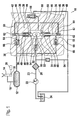
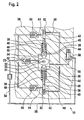
- FIG. 1 shows a fuel injection device for an internal combustion engine in a schematic representation with a high-pressure pump at the end of the delivery stroke of the pump elements and Figure 2, the high-pressure pump at the end of the suction stroke of the pump elements.
- FIG. 1 shows a fuel injection device of an internal combustion engine, for example of a motor vehicle, which has a high-pressure pump 10.
- a high-pressure pump 10 By the high pressure pump 10 while fuel is conveyed under high pressure in a memory 12, is taken from the fuel for injection to the internal combustion engine.
- an injector 14 At each cylinder of the internal combustion engine, an injector 14 is arranged, which is connected via a line 16 to the memory 12.
- the injector 14 has a control valve 18, which is controlled by an electronic control device 20, and by which the opening of the injector 14 and thus the fuel injection is controlled.
- a feed pump 22 fuel is conveyed from a fuel tank 24 to the high-pressure pump 10.
- the feed pump 22 preferably has an electric drive, but may also be driven mechanically.
- a filter 26 is arranged to filter the funded by the high pressure pump 10 fuel.
- the high-pressure pump 10 has a housing 30 in which an input shaft 32 is rotatably mounted about an axis 33 in an inner space 31.
- the drive shaft 32 is driven for example by the internal combustion engine.
- the drive shaft 32 has in the interior 31 at least one cam 34, wherein in the illustrated embodiment, a double cam is provided which has two diametrically opposed cam lobes.
- the high-pressure pump 10 has at least one pump element 36 arranged in the housing 30, with two diametrically opposite pump elements 36 being provided in the exemplary embodiment shown.
- each Pump element 36 has a pump piston 38 which is tightly guided in a cylinder bore 40 extending at least approximately radially to the axis of rotation 33 of the drive shaft 32 and defines a pump working space 42 in this with its outwardly facing end face.
- the cylinder bore 40 may be formed directly in the housing 30 or in an inserted into the housing 30 insert.
- the pump piston 38 protrudes with its radially inwardly facing end of the cylinder bore 40 and is supported via a plunger 44 on the cam 34 of the drive shaft 30 from.
- the plunger 44 is guided tightly in a bore 46 in the housing 30 and preferably has a larger diameter than the pump piston 38 in its the pump working space 42 bounding area.
- the pump piston 38 has at its piston foot 39, with which it is supported on the plunger 44, a larger diameter than in its the pump working space 42 limiting range and an approximately equal diameter as the plunger 44.
- a prestressed spring 48 for example in the form of a helical compression spring, clamped by the pump piston 38 and the piston foot 39 of the plunger 44 is held in contact with the cam 34 of the drive shaft 32.
- a cylindrical roller 50 is inserted, which rolls on the cam 34.
- the plunger 44 limited with its the pump piston 38 facing away from the bore 46 and protruding part of the interior 31 of the housing 30.
- the plunger 44 may also be omitted, in which then the pump piston 38 via its piston foot 39, in which, for example, a roller 50 may be arranged can, directly on the cam 34 is supported.
- the funded by the feed pump 22 fuel is supplied via a line 23 to the interior 31 of the housing 30 of the high-pressure pump 10.
- a check valve 52 opening towards the interior 31 is arranged, this prevents fuel from the interior 31 to the feed pump 22 can flow back.
- a line 54 from a discharge area, which may be, for example, a return 55 to the fuel tank 24.
- a line 56 leads to a discharge area, which in turn may be the return 55 to the fuel tank 24.
- a pressure valve 58 is arranged, which releases the connection to the return 55 only when a predetermined pressure in the interior 31 is exceeded and at lower pressure, the connection to the return line 55 keeps closed.
- an inlet 60 opens into the pump working chamber 42 of the pump elements 36, in which a non-return valve 62 opening into the pump working chamber 42 is arranged as an inlet valve. From the pump working chamber 42 also leads in each case from a drain 64, which opens into the memory 12 and in which a from the pump working chamber 42 to the memory 12 out opening check valve 66 is arranged as an outlet valve.
- the inlet 60 of the pump working spaces 42 of the pump elements 36 is in each case connected to the interior 31 of the housing 30 of the high-pressure pump 10.
- the pump pistons 38 of the pump elements 36 promote synchronously with each other, that is, these simultaneously perform their respective delivery stroke and their respective suction stroke.
- the check valve 52 thereby opens and funded by the feed pump 22 fuel flows into the interior 31 and fills it.
- the feed pump 22 continuously delivers fuel and the fuel delivered by the feed pump 22 when the check valve 52 is closed flows via the line 54 into the return 55.
- the plunger 44 Since the plunger 44 has a larger diameter than the pump piston 38 in their respective pump working space 42 limiting area 38 more fuel from the interior 31 is displaced by this during the suction stroke of the pump piston as sucked by the pump piston 38 into the pump work chambers 42.
- the excess amount of fuel flows with open pressure valve 58 via the line 56 in the return line 55. This is a constant emptying and filling of the interior 31 with fuel achieved and thus good lubrication and cooling of the drive of the high-pressure pump 10, in particular the drive shaft 32, and the Plunger 44 and running on the cam 34 rollers 50.
- the feed pump 22 only needs to generate a relatively low pressure in order to fill the interior 31 with fuel can.
- the plungers 44 have approximately the same diameter as the pump pistons 38 in their respective pump working space 42 limiting range, so that a correspondingly smaller amount of fuel is conveyed by the plunger 44.
- FIG. 1 shows the high-pressure pump 10 at the end of the delivery stroke of the pump piston 38, in which the pump pistons 38 are in the region of their outer dead center.
- the plunger 44 are immersed furthest in the holes 46 and the volume of the interior 31 is the largest.
- the intake valves 62 are closed, the exhaust valves 66 are opened and the check valve 52 is opened, so that fuel is conveyed by the feed pump 22 into the inner space 31.
- the high-pressure pump 10 is shown at the end of the suction stroke of the pump piston 38, in which the pump piston 38 are in the region of its inner dead center.
- the plungers 44 are immersed furthest out of the holes 46 in the interior 31, so that the volume of the interior 31 is the smallest.
- the intake valves 62 are opened, the exhaust valves 66 and the check valve 52 are closed.
Description
Die Erfindung geht aus von einer Kraftstoffeinspritzeinrichtung für eine Brennkraftmaschine nach der Gattung des Anspruchs 1.The invention relates to a fuel injection device for an internal combustion engine according to the preamble of claim 1.
Eine solche Kraftstoffeinspritzeinrichtung ist durch die WO 01/40656 A bekannt. Diese Kraftstoffeinspritzeinrichtung weist eine Hochdruckpumpe auf, durch die Kraftstoff in einen Speicher gefördert wird, aus dem Kraftstoff zur Einspritzung an der Brennkraftmaschine entnommen wird. Ausserdem ist eine Förderpumpe vorgesehen, durch die Kraftstoff aus einem Kraftstoffvorratsbehälter zur Hochdruckpumpe gefördert wird. Die Hochdruckpumpe weist ein Gehäuse und wenigstens ein Pumpenelement auf, das durch einen in einem Innenraum des Gehäuses angeordneten Antrieb angetrieben wird. Das Pumpenelement weist einen durch den Antrieb in einer Hubbewegung angetriebenen Pumpenkolben auf, der einen Pumpenarbeitsraum begrenzt. Bei einem Saughub des Pumpenkolbens saugt dieser über einen Zulauf Kraftstoff in den Pumpenarbeitsraum an und bei einem Förderhub des Pumpenkolbens verdrängt dieser über einen Ablauf Kraftstoff aus dem Pumpenarbeitsraum. Der Pumpenkolben bewegt sich bei seinem Saughub in den Innenraum des Gehäuses hinein und bei seinem Förderhub aus dem Innenraum heraus. Die Förderpumpe kann elektrisch oder mechanisch angetrieben sein. Um einen ausreichend hohen Druck erzeugen zu können ist dabei ein leistungsstarker und entsprechend teurer Antrieb für die Förderpumpe erforderlich. Alternativ können auch eine Förderpumpe mit elektrischem Antrieb geringer Leistung und zusätzlich eine Förderpumpe mit mechanischem Antrieb kombiniert werden, was aber auch teuer ist.Such a fuel injector is known from WO 01/40656 A. This fuel injection device has a high-pressure pump, is conveyed by the fuel in a memory, is taken from the fuel for injection to the internal combustion engine. In addition, a delivery pump is provided, is conveyed by the fuel from a fuel tank to the high pressure pump. The high-pressure pump has a housing and at least one pump element which is driven by a drive arranged in an interior of the housing. The pump element has a pump piston driven by the drive in a lifting movement, which limits a pump working space. During a suction stroke of the pump piston, the latter sucks fuel into the pump working chamber via an inlet and during a delivery stroke of the pump piston it displaces fuel from the pump working chamber via a drain. The pump piston moves in its suction stroke into the interior of the housing and during its delivery stroke out of the interior. The feed pump can be driven electrically or mechanically. In order to generate a sufficiently high pressure while a powerful and correspondingly expensive drive for the feed pump is required. Alternatively, a feed pump with low power electric drive and In addition, a feed pump can be combined with mechanical drive, which is also expensive.
Die erfindungsgemäße Kraftstoffeinspritzeinrichtung mit den Merkmalen gemäß Anspruch 1 hat demgegenüber den Vorteil, dass die Hochdruckpumpe zugleich eine Förderpumpe bildet, durch die der bei deren Saughüben anzusaugende Kraftstoff gefördert wird. Die Förderpumpe, durch die Kraftstoff aus dem Kraftstoffvorratsbehälter in den Innenraum des Gehäuses der Hochdruckpumpe gefördert wird, kann dabei mit geringer Leistung und entsprechend kostengünstig ausgeführt sein.The fuel injection device according to the invention with the features of claim 1 has the advantage that the high-pressure pump at the same time forms a feed pump through which the sucked at their suction strokes fuel is promoted. The feed pump, is conveyed by the fuel from the fuel tank into the interior of the housing of the high-pressure pump, it can be designed with low power and correspondingly inexpensive.
In den abhängigen Ansprüchen sind vorteilhafte Ausgestaltungen und Weiterbildungen der erfindungsgemäßen Kraftstoffeinspritzeinrichtung angegeben. Die Ausbildung gemäß Anspruch 2 ermöglicht einen kontinuierlichen Betrieb der Förderpumpe, indem von dieser bei geschlossenem Rückschlagventil geförderter Kraftstoff in den Entlastungsbereich abströmen kann. Die Ausbildung gemäß Anspruch 6 ermöglicht eine Fördermenge, die grösser ist als die erforderliche Saugmenge des Pumpenelements und somit auch eine Überströmmenge, durch die der Antrieb im Innenraum des Gehäuses geschmiert und gekühlt werden kann.In the dependent claims advantageous refinements and developments of the fuel injection device according to the invention are given. The embodiment according to claim 2 allows continuous operation of the feed pump, in that it can flow discharged from this with closed check valve fuel in the discharge area. The embodiment of claim 6 allows a flow rate that is greater than the required suction amount of the pump element and thus also an overflow, by which the drive in the interior of the housing can be lubricated and cooled.
Ein Ausführungsbeispiel der Erfindung ist in der Zeichnung dargestellt und in der nachfolgenden Beschreibung näher erläutert. Es zeigen Figur 1 eine Kraftstoffeinspritzeinrichtung für eine Brennkraftmaschine in schematischer Darstellung mit einer Hochdruckpumpe am Ende des Förderhubs von deren Pumpenelementen und Figur 2 die Hochdruckpumpe am Ende des Saughubs von deren Pumpenelementen.An embodiment of the invention is illustrated in the drawing and explained in more detail in the following description. 1 shows a fuel injection device for an internal combustion engine in a schematic representation with a high-pressure pump at the end of the delivery stroke of the pump elements and Figure 2, the high-pressure pump at the end of the suction stroke of the pump elements.
In Figur 1 ist eine Kraftstoffeinspritzeinrichtung einer Brennkraftmaschine beispielsweise eines Kraftfahrzeugs dargestellt, die eine Hochdruckpumpe 10 aufweist. Durch die Hochdruckpumpe 10 wird dabei Kraftstoff unter Hochdruck in einen Speicher 12 gefördert, aus dem Kraftstoff zur Einspritzung an der Brennkraftmaschine entnommen wird. An jedem Zylinder der Brennkraftmaschine ist dabei ein Injektor 14 angeordnet, der über eine Leitung 16 mit dem Speicher 12 verbunden ist. Der Injektor 14 weist ein Steuerventil 18 auf, das durch eine elektronische Steuereinrichtung 20 angesteuert wird, und durch das die Öffnung des Injektors 14 und damit die Kraftstoffeinspritzung gesteuert wird.FIG. 1 shows a fuel injection device of an internal combustion engine, for example of a motor vehicle, which has a high-
Durch eine Förderpumpe 22 wird Kraftstoff aus einem Kraftstoffvorratsbehälter 24 zur Hochdruckpumpe 10 gefördert. Die Förderpumpe 22 weist vorzugsweise einen elektrischen Antrieb auf, kann aber auch mechanisch angetrieben sein. Zwischen der Förderpumpe 22 und der Hochdruckpumpe 10 ist ein Filter 26 angeordnet, um den durch die Hochdruckpumpe 10 geförderten Kraftstoff zu filtern.By a
Die Hochdruckpumpe 10 weist ein Gehäuse 30 auf, in dem in einem Innenraum 31 eine Antriebswelle 32 um eine Achse 33 drehbar gelagert ist. Die Antriebswelle 32 wird beispielsweise durch die Brennkraftmaschine angetrieben. Die Antriebswelle 32 weist im Innenraum 31 wenigstens einen Nocken 34 auf, wobei beim dargestellten Ausführungsbeispiel ein Doppelnocken vorgesehen ist, der zwei einander diametral gegenüberliegende Nockenerhebungen aufweist. Die Hochdruckpumpe 10 weist wenigstens ein im Gehäuse 30 angeordnetes Pumpenelement 36 auf, wobei beim dargestellten Ausführungsbeispiel zwei einander diametral gegenüberliegende Pumpenelemente 36 vorgesehen sind. Jedes Pumpenelement 36 weist einen Pumpenkolben 38 auf, der in einer zumindest annähernd radial zur Drehachse 33 der Antriebswelle 32 verlaufenden Zylinderbohrung 40 dicht geführt ist und in dieser mit seiner nach aussen weisenden Stirnseite einen Pumpenarbeitsraum 42 begrenzt. Die Zylinderbohrung 40 kann direkt im Gehäuse 30 oder in einem in das Gehäuse 30 eingefügten Einsatz ausgebildet sein. Der Pumpenkolben 38 ragt mit seinem radial nach innen weisenden Ende aus der Zylinderbohrung 40 heraus und stützt sich über einen Stössel 44 am Nocken 34 der Antriebswelle 30 ab. Der Stössel 44 ist in einer Bohrung 46 im Gehäuse 30 dicht geführt und weist vorzugsweise einen grösseren Durchmesser auf als der Pumpenkolben 38 in seinem den Pumpenarbeitsraum 42 begrenzenden Bereich. Der Pumpenkolben 38 weist an seinem Kolbenfuss 39, mit dem er sich am Stössel 44 abstützt, einen grösseren Durchmesser als in seinem den Pumpenarbeitsraum 42 begrenzenden Bereich und einen etwa gleich grossen Durchmesser wie der Stössel 44 auf. Zwischen dem Gehäuse 30 und dem Kolbenfuss 39 ist eine vorgespannte Feder 48, beispielsweise in Form einer Schraubendruckfeder, eingespannt, durch die der Pumpenkolben 38 und über dessen Kolbenfuss 39 der Stössel 44 in Anlage am Nocken 34 der Antriebswelle 32 gehalten wird. In die dem Nocken 34 zugewandte Seite des Stössels 44 ist eine zylindrische Rolle 50 eingesetzt, die auf dem Nocken 34 abrollt. Der Stössel 44 begrenzt mit seiner dem Pumpenkolben 38 abgewandten und aus der Bohrung 46 ragenden Teil den Innenraum 31 des Gehäuses 30. Der Stössel 44 kann auch entfallen, wobei sich dann der Pumpenkolben 38 über seinen Kolbenfuss 39, in dem beispielsweise eine Rolle 50 angeordnet sein kann, direkt am Nocken 34 abstützt.The high-
Der durch die Förderpumpe 22 geförderte Kraftstoff wird über eine Leitung 23 dem Innenraum 31 des Gehäuses 30 der Hochdruckpumpe 10 zugeführt. In der Leitung 23 ist ein zum Innenraum 31 hin öffnendes Rückschlagventil 52 angeordnet, das verhindert, dass aus dem Innenraum 31 Kraftstoff zur Förderpumpe 22 zurückströmen kann. Von der Leitung 23 führt zwischen der Förderpumpe 22 und dem Rückschlagventil 52 eine Leitung 54 zu einem Entlastungsbereich ab, der beispielsweise ein Rücklauf 55 zum Kraftstoffvorratsbehälter 24 sein kann. Vom Innenraum 31 des Gehäuses 30 der Hochdruckpumpe 10 führt eine Leitung 56 zu einem Entlastungsbereich ab, der wiederum der Rücklauf 55 zum Kraftstoffvorratsbehälter 24 sein kann. In der Leitung 56 ist ein Druckventil 58 angeordnet, das die Verbindung zum Rücklauf 55 erst bei Überschreiten eines vorgegebenen Drucks im Innenraum 31 freigibt und bei geringerem Druck die Verbindung zum Rücklauf 55 verschlossen hält.The funded by the
In den Pumpenarbeitsraum 42 der Pumpenelemente 36 mündet jeweils ein Zulauf 60, in dem ein in den Pumpenarbeitsraum 42 öffnendes Rückschlagventil 62 als Einlassventil angeordnet ist. Vom Pumpenarbeitsraum 42 führt ausserdem jeweils ein Ablauf 64 ab, der in den Speicher 12 mündet und in dem ein aus dem Pumpenarbeitsraum 42 zum Speicher 12 hin öffnendes Rückschlagventil 66 als Auslassventil angeordnet ist. Der Zulauf 60 der Pumpenarbeitsräume 42 der Pumpenelemente 36 ist jeweils mit dem Innenraum 31 des Gehäuses 30 der Hochdruckpumpe 10 verbunden. Die Pumpenkolben 38 der Pumpenelemente 36 fördern synchron miteinander, das heisst diese führen gleichzeitig ihren jeweiligen Förderhub und ihren jeweiligen Saughub aus. Wenn die Pumpenkolben 38 ihren Saughub ausführen, so bewegen diese sich durch die Federn 48 bewirkt entsprechend dem Profil des Nockens 34, an dem die Stössel 44 über die Rollen 50 anliegen, radial nach innen und deren Stössel 44 bewegen sich aus der Bohrung 46 heraus in den Innenraum 31 hinein. Hierbei wird das Volumen des Innenraums 31 verringert, so dass der Druck im Innenraum 31 steigt, wobei durch das Rückschlagventil 52 verhindert wird, dass Kraftstoff in den Rücklauf 55 verdrängt wird. Beim Saughub der Pumpenkolben 38 herrscht in den Pumpenarbeitsräumen 42 ein geringerer Druck als im Innenraum 31, so dass bei geöffneten Einlassventilen 62 Kraftstoff aus dem Innenraum 31 verdrängt und in die Pumpenarbeitsräume 42 gefördert wird. Beim Förderhub der Pumpenkolben 38 schliessen die Einlassventile 62 und bei Überschreiten eines vorgegebenen Drucks öffnen die Auslassventile 66, so dass Kraftstoff über den Ablauf 64 in den Speicher 12 gefördert wird.In each case, an
Beim Förderhub der Pumpenkolben 38 bewegen diese sich durch den Nocken 34 bewirkt gegen die Kraft der Federn 48 radial nach aussen und die Stössel 44 bewegen sich in die Bohrung 46 hinein, so dass das Volumen des Innenraums 31 vergrössert wird. Das Rückschlagventil 52 öffnet dabei und durch die Förderpumpe 22 geförderter Kraftstoff strömt in den Innenraum 31 ein und befüllt diesen. Die Förderpumpe 22 fördert kontinuierlich Kraftstoff und der bei geschlossenem Rückschlagventil 52 durch die Förderpumpe 22 geförderte Kraftstoff strömt über die Leitung 54 in den Rücklauf 55.During the delivery stroke of the
Da die Stössel 44 einen grösseren Durchmesser aufweisen als die Pumpenkolben 38 in deren den jeweiligen Pumpenarbeitsraum 42 begrenzendem Bereich wird durch diese beim Saughub der Pumpenkolben 38 mehr Kraftstoff aus dem Innenraum 31 verdrängt als durch die Pumpenkolben 38 in die Pumpenarbeitsräume 42 angesaugt wird. Die überschüssige Kraftstoffmenge strömt bei geöffnetem Druckventil 58 über die Leitung 56 in den Rücklauf 55. Hierdurch wird ein ständiges Entleeren und Befüllen des Innenraums 31 mit Kraftstoff erreicht und somit eine gute Schmierung und Kühlung des Antriebs der Hochdruckpumpe 10, insbesondere der Antriebswelle 32, sowie der Stössel 44 und der auf dem Nocken 34 ablaufenden Rollen 50. Die Förderpumpe 22 braucht dabei nur einen relativ geringen Druck zu erzeugen, um den Innenraum 31 mit Kraftstoff befüllen zu können. Beim Saughub der Pumpenkolben 38 wird durch diese im Innenraum 31 ein relativ hoher Druck erzeugt, der eine ausreichende und schnelle Befüllung der Pumpenarbeitsräume 42 ermöglicht. Es kann auch vorgesehen sein, dass die Stössel 44 etwa denselben Durchmesser wie die Pumpenkolben 38 in deren den jeweiligen Pumpenarbeitsraum 42 begrenzendem Bereich aufweisen, so dass eine entsprechend geringere Kraftstoffmenge durch die Stössel 44 gefördert wird.Since the
In Figur 1 ist die Hochdruckpumpe 10 am Ende des Förderhubs der Pumpenkolben 38 dargestellt, bei dem sich die Pumpenkolben 38 im Bereich ihres äusseren Totpunkts befinden. Die Stössel 44 sind dabei am weitesten in die Bohrungen 46 eingetaucht und das Volumen des Innenraums 31 ist am grössten. Die Einlassventile 62 sind geschlossen, die Auslassventile 66 sind geöffnet und das Rückschlagventil 52 ist geöffnet, so dass Kraftstoff durch die Förderpumpe 22 in den Innenraum 31 gefördert wird. In Figur 2 ist die Hochdruckpumpe 10 am Ende des Saughubs der Pumpenkolben 38 dargestellt, bei dem sich die Pumpenkolben 38 im Bereich ihres inneren Totpunkts befinden. Die Stössel 44 sind dabei am weitesten aus den Bohrungen 46 heraus in den Innenraum 31 eingetaucht, so dass das Volumen des Innenraums 31 am kleinsten ist. Die Einlassventile 62 sind geöffnet, die Auslassventile 66 und das Rückschlagventil 52 sind geschlossen.FIG. 1 shows the high-
Claims (10)
- Fuel injection device for an internal combustion engine, having a high-pressure pump (10) which feeds fuel into an accumulator (12) from which fuel is extracted for injection in the internal combustion engine, having a feed pump (22) which feeds fuel from a fuel reservoir vessel (24) to the high-pressure pump (10), the high-pressure pump (10) having a housing (30) with an interior (31) in which a drive (32, 34) for at least one pump element (36) of the high-pressure pump (10) is arranged, the pump element (36) having a pump piston (38) which is driven in a reciprocating movement by the drive (32, 34) and which bounds a pump working space (42) into which fuel is fed via an inlet (60) during an induction stroke of the pump piston (38) and from which fuel is expelled into the accumulator (12) via an outlet (64) during a delivery stroke of the pump piston (38), the pump piston (38) moving towards the interior (31) during its induction stroke and away from the interior (31) during its delivery stroke, characterized in that the feed pump (22) feeds fuel into the interior (31) via a connection (23) which has a non-return valve (52) which opens towards the interior (31) of the housing (30), and in that the inlet (60) of the pump working space (42) is connected to the interior (31) so that fuel which is expelled from the interior (31) during the induction stroke of the pump piston (38) by the movement of said pump piston (38) in the direction of the interior (31) is sucked into the pump working space (42).
- Fuel injection device according to Claim 1, characterized in that a connection (54) leads off to the relief area (55) from the connection (23) between the feed pump (22) and the interior (31) of the housing (30), upstream of the non-return valve (52).
- Fuel injection device according to Claim 1 or 2, characterized in that a prestressed spring (48) acts on the pump piston (38) in the direction of its induction stroke.
- Fuel injection device according to one of Claims 1 to 3, characterized in that the drive has a drive shaft (32) with at least one cam (34) which brings about the reciprocating movement of the pump piston (38).
- Fuel injection device according to one of Claims 1 to 4, characterized in that the pump piston (38) is supported on the drive (32, 34) by means of a tappet (44) which is guided in a sealed fashion in a bore (46) in the housing (30) and which partially bounds the interior (31).
- Fuel injection device according to Claim 5, characterized in that the tappet (44) has a larger diameter than the pump piston (38) in its region bounding the pump working space (42).
- Fuel injection device according to one of Claims 4 to 6, characterized in that the cam (34) is a multiple cam.
- Fuel injection device according to one of the preceding claims, characterized in that a non-return valve (62) which opens towards the pump working space (42) is arranged in the inlet (60) of the pump working space (42).
- Fuel injection device according to one of the preceding claims, characterized in that the high-pressure pump (10) has a plurality of pump elements (36).
- Fuel injection device according to one of the preceding claims, characterized in that a connection (56) leads off from the interior (31) of the housing (30) to a relief region (55) in which a pressure valve (58) which opens the connection (54) when a predefined pressure in the interior (31) is exceeded is arranged.
Applications Claiming Priority (3)
| Application Number | Priority Date | Filing Date | Title |
|---|---|---|---|
| DE10307877A DE10307877A1 (en) | 2003-02-25 | 2003-02-25 | Fuel injection device for an internal combustion engine |
| DE10307877 | 2003-02-25 | ||
| PCT/DE2003/003394 WO2004076847A1 (en) | 2003-02-25 | 2003-10-13 | Fuel injection device for an internal combustion engine |
Publications (2)
| Publication Number | Publication Date |
|---|---|
| EP1599668A1 EP1599668A1 (en) | 2005-11-30 |
| EP1599668B1 true EP1599668B1 (en) | 2006-07-26 |
Family
ID=32797716
Family Applications (1)
| Application Number | Title | Priority Date | Filing Date |
|---|---|---|---|
| EP03773513A Expired - Lifetime EP1599668B1 (en) | 2003-02-25 | 2003-10-13 | Fuel injection device for an internal combustion engine |
Country Status (5)
| Country | Link |
|---|---|
| US (1) | US7850435B2 (en) |
| EP (1) | EP1599668B1 (en) |
| JP (1) | JP4461026B2 (en) |
| DE (2) | DE10307877A1 (en) |
| WO (1) | WO2004076847A1 (en) |
Families Citing this family (11)
| Publication number | Priority date | Publication date | Assignee | Title |
|---|---|---|---|---|
| DE102007038519A1 (en) * | 2007-06-28 | 2009-01-02 | Robert Bosch Gmbh | High pressure fuel pump assembly, which is driven by the valve train of an internal combustion engine |
| DE102007034036A1 (en) * | 2007-07-20 | 2009-01-22 | Robert Bosch Gmbh | High-pressure fuel pump with roller tappet |
| JP5094349B2 (en) * | 2007-11-30 | 2012-12-12 | 株式会社日立産機システム | Cylinder device, compressor, and method of manufacturing cylinder device |
| US20100119393A1 (en) * | 2008-11-12 | 2010-05-13 | Delphi Technologies, Inc. | Hydraulic pump assembly |
| IT1395139B1 (en) * | 2009-08-06 | 2012-09-05 | Bosch Gmbh Robert | HIGH PRESSURE PUMP FOR FUEL SUPPLY TO AN INTERNAL COMBUSTION ENGINE |
| DE102011004939A1 (en) | 2011-03-02 | 2012-09-06 | Robert Bosch Gmbh | Fuel conveying device for fuel injection system of internal combustion engine, is provided with delivery pump that conveys fuel from reservoir to high pressure pump |
| CN102979732B (en) * | 2012-10-30 | 2015-10-28 | 无锡鸿声铝业有限公司 | Vacuum rotatory sealing pump ball friction oil charging structure |
| DE102012224408A1 (en) * | 2012-12-27 | 2014-07-17 | Robert Bosch Gmbh | Fuel injection system e.g. common-rail injection system of internal combustion engine, has return-flow pipe whose downstream is connected with high-pressure pump that is integrated with spring-loaded valve which is check valve |
| JP6040912B2 (en) * | 2013-11-12 | 2016-12-07 | 株式会社デンソー | High pressure pump |
| DE102014225982A1 (en) * | 2014-12-16 | 2016-06-16 | Robert Bosch Gmbh | Pump, in particular high-pressure fuel pump |
| EP3808968A1 (en) * | 2019-10-16 | 2021-04-21 | Volvo Car Corporation | An arrangement for transferring force from a camshaft to an output device |
Family Cites Families (11)
| Publication number | Priority date | Publication date | Assignee | Title |
|---|---|---|---|---|
| DE19531811A1 (en) * | 1995-08-30 | 1997-03-06 | Bosch Gmbh Robert | Fuel injection pump |
| BR9904868A (en) * | 1998-02-27 | 2000-09-26 | Stanadyne Automotive Corp | Fuel supply pump and process of operating a fuel injection system |
| US6694950B2 (en) * | 1999-02-17 | 2004-02-24 | Stanadyne Corporation | Hybrid control method for fuel pump using intermittent recirculation at low and high engine speeds |
| DE19926308A1 (en) * | 1999-06-09 | 2000-12-21 | Bosch Gmbh Robert | Pump assembly for fuel |
| DE19933567C1 (en) | 1999-07-16 | 2001-02-01 | Siemens Ag | Combustion engine fuel-injection system esp. for diesel engine |
| DE19937673A1 (en) | 1999-08-10 | 2001-02-22 | Siemens Ag | Injection system for an internal combustion engine |
| IT1310754B1 (en) * | 1999-11-30 | 2002-02-22 | Elasis Sistema Ricerca Fiat | VALVE SYSTEM FOR INLET PRESSURE CONTROL OF A LIQUID IN A HIGH PRESSURE PUMP, AND RELATED VALVE |
| DE10010945B4 (en) | 2000-03-06 | 2004-07-22 | Robert Bosch Gmbh | Pump for supplying a fuel injection system and a hydraulic valve control for internal combustion engines |
| US6722864B2 (en) * | 2001-12-12 | 2004-04-20 | Denso Corporation | Fuel injection pump |
| DE10200792A1 (en) * | 2002-01-11 | 2003-07-31 | Bosch Gmbh Robert | Fuel pump for an internal combustion engine |
| EP1803933B1 (en) * | 2005-12-27 | 2010-05-19 | C.R.F. Societa Consortile per Azioni | High-pressure pump for a fuel, with sump in communication with the fuel inlet |
-
2003
- 2003-02-25 DE DE10307877A patent/DE10307877A1/en not_active Withdrawn
- 2003-10-13 EP EP03773513A patent/EP1599668B1/en not_active Expired - Lifetime
- 2003-10-13 JP JP2004568633A patent/JP4461026B2/en not_active Expired - Fee Related
- 2003-10-13 DE DE50304406T patent/DE50304406D1/en not_active Expired - Lifetime
- 2003-10-13 WO PCT/DE2003/003394 patent/WO2004076847A1/en active IP Right Grant
- 2003-10-13 US US10/546,655 patent/US7850435B2/en not_active Expired - Fee Related
Also Published As
| Publication number | Publication date |
|---|---|
| JP2006514202A (en) | 2006-04-27 |
| US20060193736A1 (en) | 2006-08-31 |
| DE10307877A1 (en) | 2004-09-02 |
| JP4461026B2 (en) | 2010-05-12 |
| DE50304406D1 (en) | 2006-09-07 |
| US7850435B2 (en) | 2010-12-14 |
| EP1599668A1 (en) | 2005-11-30 |
| WO2004076847A1 (en) | 2004-09-10 |
Similar Documents
| Publication | Publication Date | Title |
|---|---|---|
| EP2207955B1 (en) | Fuel overflow valve for a fuel injection system, and fuel injection system having a fuel overflow valve | |
| EP2798191B1 (en) | Fuel overflow valve for a fuel injection device, and fuel injection device comprising fuel overflow valve | |
| DE10118754B4 (en) | high pressure pump | |
| WO2005111405A1 (en) | High-pressure pump for a fuel injection device pertaining to an internal combustion engine | |
| EP1599668B1 (en) | Fuel injection device for an internal combustion engine | |
| WO2005124153A1 (en) | High-pressure pump for a fuel injection device of an internal combustion engine | |
| EP2795095B1 (en) | Pump, in particular a fuel pump for a fuel injection system | |
| DE102008017824A1 (en) | Tappet assembly for high-pressure pump of internal-combustion engine in motor vehicle, has retaining ring and formed such that movement of roller is controlled in roller shoe in direction of roller longitudinal axis | |
| EP1537334B1 (en) | Pump, especially for a fuel injection device for an internal combustion engine | |
| EP3061967B1 (en) | Pump, in particular high-pressure fuel pump | |
| DE102008062518B4 (en) | high pressure pump | |
| EP2134966B1 (en) | Pump, in particular high-pressure fuel pump | |
| WO2005015017A1 (en) | High pressure pump for a fuel injection device of a combustion engine | |
| EP2143946A1 (en) | Pump array | |
| DE10355028A1 (en) | High pressure pump especially for vehicle has the piston rod and cam follower made in one piece and spring loaded to press onto the drive cam | |
| WO2020244882A1 (en) | Pump, in particular a high-pressure fuel pump | |
| WO2009013175A1 (en) | Pump, particularly high-pressure fuel pump | |
| DE10210300B4 (en) | Pump element for a high-pressure pump and high-pressure pump with controllable flow rate | |
| DE102004023962A1 (en) | Fuel high pressure pump and injection system controlling method, involves reducing number of discharge strokes of fuel high-pressure pump relative to number of injections, if injection quantity is smaller than minimum output | |
| DE102021209214A1 (en) | Pump group with a high-pressure pump and a low-pressure pump | |
| EP2872778B1 (en) | High-pressure pump | |
| DE102012201308A1 (en) | High-pressure pump for delivering fluid e.g. diesel to diesel engine, has elastic sealing element to seal connecting unit for connecting closure element and piston carrier, with respect to inlet and outlet channels | |
| DE102022201334A1 (en) | Pump, in particular high-pressure fuel pump | |
| WO2013098259A1 (en) | Pump, in particular high-pressure fuel pump for a fuel injection device | |
| DE102010043404A1 (en) | High pressure pump for supplying fluid, has pump housing, where pump unit is partially arranged in housing recess, and guide is mechanically coupled with cover such that covering recess and guiding recess form common recess |
Legal Events
| Date | Code | Title | Description |
|---|---|---|---|
| PUAI | Public reference made under article 153(3) epc to a published international application that has entered the european phase |
Free format text: ORIGINAL CODE: 0009012 |
|
| 17P | Request for examination filed |
Effective date: 20050926 |
|
| AK | Designated contracting states |
Kind code of ref document: A1 Designated state(s): AT BE BG CH CY CZ DE DK EE ES FI FR GB GR HU IE IT LI LU MC NL PT RO SE SI SK TR |
|
| GRAP | Despatch of communication of intention to grant a patent |
Free format text: ORIGINAL CODE: EPIDOSNIGR1 |
|
| RBV | Designated contracting states (corrected) |
Designated state(s): DE FR IT |
|
| GRAS | Grant fee paid |
Free format text: ORIGINAL CODE: EPIDOSNIGR3 |
|
| GRAA | (expected) grant |
Free format text: ORIGINAL CODE: 0009210 |
|
| AK | Designated contracting states |
Kind code of ref document: B1 Designated state(s): DE FR IT |
|
| PG25 | Lapsed in a contracting state [announced via postgrant information from national office to epo] |
Ref country code: IT Free format text: LAPSE BECAUSE OF FAILURE TO SUBMIT A TRANSLATION OF THE DESCRIPTION OR TO PAY THE FEE WITHIN THE PRESCRIBED TIME-LIMIT;WARNING: LAPSES OF ITALIAN PATENTS WITH EFFECTIVE DATE BEFORE 2007 MAY HAVE OCCURRED AT ANY TIME BEFORE 2007. THE CORRECT EFFECTIVE DATE MAY BE DIFFERENT FROM THE ONE RECORDED. Effective date: 20060726 |
|
| REF | Corresponds to: |
Ref document number: 50304406 Country of ref document: DE Date of ref document: 20060907 Kind code of ref document: P |
|
| PGFP | Annual fee paid to national office [announced via postgrant information from national office to epo] |
Ref country code: IT Payment date: 20061031 Year of fee payment: 4 |
|
| ET | Fr: translation filed | ||
| PLBE | No opposition filed within time limit |
Free format text: ORIGINAL CODE: 0009261 |
|
| STAA | Information on the status of an ep patent application or granted ep patent |
Free format text: STATUS: NO OPPOSITION FILED WITHIN TIME LIMIT |
|
| 26N | No opposition filed |
Effective date: 20070427 |
|
| REG | Reference to a national code |
Ref country code: FR Ref legal event code: ST Effective date: 20080630 |
|
| PGFP | Annual fee paid to national office [announced via postgrant information from national office to epo] |
Ref country code: FR Payment date: 20061020 Year of fee payment: 4 |
|
| PG25 | Lapsed in a contracting state [announced via postgrant information from national office to epo] |
Ref country code: FR Free format text: LAPSE BECAUSE OF NON-PAYMENT OF DUE FEES Effective date: 20071031 |
|
| PG25 | Lapsed in a contracting state [announced via postgrant information from national office to epo] |
Ref country code: IT Free format text: LAPSE BECAUSE OF NON-PAYMENT OF DUE FEES Effective date: 20071013 |
|
| PGFP | Annual fee paid to national office [announced via postgrant information from national office to epo] |
Ref country code: DE Payment date: 20181206 Year of fee payment: 16 |
|
| REG | Reference to a national code |
Ref country code: DE Ref legal event code: R119 Ref document number: 50304406 Country of ref document: DE |
|
| PG25 | Lapsed in a contracting state [announced via postgrant information from national office to epo] |
Ref country code: DE Free format text: LAPSE BECAUSE OF NON-PAYMENT OF DUE FEES Effective date: 20200501 |