EP1537334B1 - Pompe, notamment pour un systeme d'injection de carburant destine a un moteur a combustion interne - Google Patents
Pompe, notamment pour un systeme d'injection de carburant destine a un moteur a combustion interne Download PDFInfo
- Publication number
- EP1537334B1 EP1537334B1 EP03739364A EP03739364A EP1537334B1 EP 1537334 B1 EP1537334 B1 EP 1537334B1 EP 03739364 A EP03739364 A EP 03739364A EP 03739364 A EP03739364 A EP 03739364A EP 1537334 B1 EP1537334 B1 EP 1537334B1
- Authority
- EP
- European Patent Office
- Prior art keywords
- pump
- blind bore
- bore
- housing part
- valve
- Prior art date
- Legal status (The legal status is an assumption and is not a legal conclusion. Google has not performed a legal analysis and makes no representation as to the accuracy of the status listed.)
- Expired - Lifetime
Links
- 239000000446 fuel Substances 0.000 title claims description 21
- 238000002485 combustion reaction Methods 0.000 title claims description 5
- 238000002347 injection Methods 0.000 title claims description 4
- 239000007924 injection Substances 0.000 title claims description 4
- 230000007704 transition Effects 0.000 claims description 4
- 230000006835 compression Effects 0.000 description 2
- 238000007906 compression Methods 0.000 description 2
- 238000004519 manufacturing process Methods 0.000 description 2
- 230000001419 dependent effect Effects 0.000 description 1
- 238000011161 development Methods 0.000 description 1
- 230000018109 developmental process Effects 0.000 description 1
- 239000002828 fuel tank Substances 0.000 description 1
- 238000007789 sealing Methods 0.000 description 1
Images
Classifications
-
- F—MECHANICAL ENGINEERING; LIGHTING; HEATING; WEAPONS; BLASTING
- F02—COMBUSTION ENGINES; HOT-GAS OR COMBUSTION-PRODUCT ENGINE PLANTS
- F02M—SUPPLYING COMBUSTION ENGINES IN GENERAL WITH COMBUSTIBLE MIXTURES OR CONSTITUENTS THEREOF
- F02M55/00—Fuel-injection apparatus characterised by their fuel conduits or their venting means; Arrangements of conduits between fuel tank and pump F02M37/00
- F02M55/004—Joints; Sealings
- F02M55/005—Joints; Sealings for high pressure conduits, e.g. connected to pump outlet or to injector inlet
-
- F—MECHANICAL ENGINEERING; LIGHTING; HEATING; WEAPONS; BLASTING
- F02—COMBUSTION ENGINES; HOT-GAS OR COMBUSTION-PRODUCT ENGINE PLANTS
- F02M—SUPPLYING COMBUSTION ENGINES IN GENERAL WITH COMBUSTIBLE MIXTURES OR CONSTITUENTS THEREOF
- F02M59/00—Pumps specially adapted for fuel-injection and not provided for in groups F02M39/00 -F02M57/00, e.g. rotary cylinder-block type of pumps
- F02M59/44—Details, components parts, or accessories not provided for in, or of interest apart from, the apparatus of groups F02M59/02 - F02M59/42; Pumps having transducers, e.g. to measure displacement of pump rack or piston
-
- F—MECHANICAL ENGINEERING; LIGHTING; HEATING; WEAPONS; BLASTING
- F04—POSITIVE - DISPLACEMENT MACHINES FOR LIQUIDS; PUMPS FOR LIQUIDS OR ELASTIC FLUIDS
- F04B—POSITIVE-DISPLACEMENT MACHINES FOR LIQUIDS; PUMPS
- F04B1/00—Multi-cylinder machines or pumps characterised by number or arrangement of cylinders
- F04B1/04—Multi-cylinder machines or pumps characterised by number or arrangement of cylinders having cylinders in star- or fan-arrangement
- F04B1/0404—Details or component parts
- F04B1/0452—Distribution members, e.g. valves
-
- F—MECHANICAL ENGINEERING; LIGHTING; HEATING; WEAPONS; BLASTING
- F04—POSITIVE - DISPLACEMENT MACHINES FOR LIQUIDS; PUMPS FOR LIQUIDS OR ELASTIC FLUIDS
- F04B—POSITIVE-DISPLACEMENT MACHINES FOR LIQUIDS; PUMPS
- F04B53/00—Component parts, details or accessories not provided for in, or of interest apart from, groups F04B1/00 - F04B23/00 or F04B39/00 - F04B47/00
- F04B53/16—Casings; Cylinders; Cylinder liners or heads; Fluid connections
Definitions
- the invention relates to a pump, in particular for a fuel injection device for an internal combustion engine according to the preamble of claim 1.
- Such a pump is through the DE 198 48 035 A1 known.
- This pump has at least one pump element with a pump piston which is tightly guided in a cylinder bore of a housing part and delimits a pump working space in the cylinder bore with its end face.
- the pump piston is driven in a stroke.
- the pump working space has a connection with an inlet channel controlled by an inlet valve opening into the pump working space, and a connection with a drainage channel controlled by an outlet valve opening from the pump working space.
- the inlet valve has a valve member cooperating with a valve seat, which is acted upon by a valve spring to the valve seat.
- the opening into the pump working chamber part of the inlet channel is formed by an inserted into a bore of the housing part separate component, on which also the valve seat is formed.
- the bore of the housing part is closed with a screw plug. Due to the many items, the production and assembly of the known pump is complicated and expensive.
- the pump according to the invention with the features of claim 1 has the advantage that it is easy and inexpensive to manufacture and assemble, since the number of their parts is reduced.
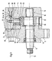
- FIG. 1 a pump in a longitudinal section
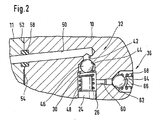
- FIG. 2 one in FIG. 1 With II designated section of the pump in an enlarged view.
- a pump is shown, which is provided in particular for a fuel injection device for an internal combustion engine, for example a motor vehicle.
- the pump thereby fuel under high pressure of up to 2000 bar promoted, for example, in a memory.
- the pump has a housing which has, for example, a housing part 10 and a flange part 11 connected thereto.
- a drive shaft 12 is arranged through which one or more arranged in the housing pump elements 14 are driven.
- a plurality of pump elements 14 are arranged distributed over the circumference of the drive shaft 12.
- the drive shaft 12 is connected via a bearing 16 in the housing part 10 and over a bearing 18 in the flange 11 is rotatably mounted about an axis 13 and is driven in a manner not shown by the internal combustion engine.
- the drive shaft 12 has an eccentric portion 20 on which a cam ring 22 is mounted.
- the pump element 14 has a pump piston 24 which is displaceably guided in an at least approximately radially to the drive shaft 12 extending cylinder bore 26 of the housing part 10.
- the pump piston 24 is supported with its piston foot 25 on the cam ring 22, wherein the piston 25 is held by a spring 28, which is supported on the one hand on the housing part 10 and the other hand on the piston 25 in contact with the cam ring 22.
- a pump working chamber 30 is limited in the cylinder bore 26 with its front side.
- the pump working space 30 can be connected to a fuel feed channel 34, in which low pressure prevails, by means of an inlet valve 32 which opens into the pump working chamber 30.
- the pump working chamber 30 can also be connected to the accumulator by means of an outlet valve 36 which opens toward the accumulator via a fuel outlet channel 38 extending in the housing part 10.
- the pump piston 24 When the pump piston 24 moves radially inward, it performs a suction stroke, wherein the inlet valve 32 is opened, so that fuel flows into the pump working chamber 30 via the fuel inlet passage 34, while the outlet valve 36 is closed.
- the pump piston 24 moves radially outward, it performs a delivery stroke, wherein the inlet valve 32 is closed and the fuel compressed by the pump piston 24 passes through the open outlet valve 36 under high pressure via the fuel drain passage 38 into the memory.
- a first blind bore 42 adjoins the pump work chamber 30, which is arranged in the end region of the cylinder bore 26 which is radially remote from the drive shaft 12, as part of the fuel feed channel 34.
- the first blind bore 42 has compared to the cylinder bore 26 has a smaller diameter and preferably extends at least approximately coaxial with the cylinder bore 26.
- the first blind bore 42 terminates within the housing part 10.
- the transition from the cylinder bore 26 to the first blind bore 42 is for example at least approximately conical and forms a valve seat 44 for the inlet valve 32.
- the inlet valve 32 has a valve member 46, which is formed for example as a ball, and which cooperates with the valve seat 44 for controlling the connection of the pump chamber 30 with the fuel supply passage 34.
- valve member 46 is acted upon by a prestressed valve spring 48, for example in the form of a helical compression spring, toward the valve seat 44.
- a support member may be arranged in the form of a spring plate.
- the valve spring 48 may be fixedly supported on the housing part 10 or as shown in the figure on the end face of the pump piston 24th
- first blind bore 42 opens as a further part of the fuel inlet channel 34 introduced in the housing part 10 second blind bore 50, which also ends in the housing part 10.
- the second blind bore 50 extends inclined to the first blind bore 42, preferably at least approximately perpendicular to the first blind bore 42 and at least approximately parallel to the rotational axis 13 of the drive shaft 12.
- the second blind bore 50 is introduced from a side facing the flange 11 side surface 52 of the housing part 10.
- the fuel inlet channel 34 is set starting from a side surface 54 the flange 11, wherein on the flange 11, a connection 56 may be provided for a supply line via which fuel is supplied from a fuel tank, for example by a feed pump.
- a sealing element 58 may be clamped.
- the mutually facing side surfaces 52 and 54 of the housing part 10 and the flange 11 extend for example at least approximately perpendicular to the axis of rotation 13 of the drive shaft 12 and may be flat.
- the housing part 10 and the flange 11 are connected to each other in a manner not shown, for example by means of several screws.
- the fuel channel 34 in the housing part 10 forming blind holes 42 and 50 can be introduced in a simple manner from the cylinder bore 26 forth or from the side surface 52 ago in the housing part 10.
- the housing part 10 has no openings for the fuel channel 34 on its outer side.
- For the inlet valve 32 only the valve member 46 and the valve spring 48 and optionally the support element arranged between them are required as additional components.
- a common housing part 10 is provided for a plurality of pump elements 14, in which a corresponding number of the cylinder bores 26 and the blind holes 42 and 50 are introduced.
- a separate housing part 10 is provided for each pump element 14, in each of which only a cylinder bore 26 and a blind bore 42,50 is introduced. The housing parts 10 of the pump elements 14 are then connected together in a suitable manner.
- a bore 60 which is at least approximately perpendicular to the longitudinal axis of the Cylinder bore 26 extends.
- the bore 60 is formed multi-stepped in diameter, with their opening into the pump working chamber 30 end portion has a small diameter.
- a central portion of the bore 60 joins away from the pump working space 30, wherein the transition between the end portion and the central portion may be approximately conical, for example, and forms a valve seat 62 for the outlet valve 36.
- a valve member 64 of the outlet valve 36 for example in the form of a ball, cooperates with the fuel outlet channel 38 for controlling the connection of the pump working chamber 30.
- a screw plug 66 is screwed. Between the plug screw 66 and the valve member 64 is a biased valve spring 68, for example in the form of a helical compression spring, clamped by the valve member 64 is acted upon the valve seat 62 out.
Claims (7)
- Pompe, notamment pour un système d'injection de carburant destiné à un moteur à combustion interne, avec au moins un élément de pompe (14), qui comprend un piston de pompe (24) guidé de façon étanche dans un alésage de cylindre (26) d'une partie de boîtier (10), qui limite une chambre de travail de pompe (30) dans l'alésage de cylindre (26) et qui est mis en mouvement dans une course, dans laquelle la chambre de travail de pompe (30) présente une communication avec un canal d'arrivée (34) commandée par une soupape d'admission (32) s'ouvrant dans la chambre de travail de pompe (30) et une communication avec un canal d'évacuation (38) commandée par une soupape d'échappement (36) s'ouvrant hors de la chambre de travail de pompe (30), dans laquelle la soupape d'admission (32) présente un organe de soupape (46) coopérant avec un siège de soupape (44), qui est poussé dans une direction de fermeture vers le siège de soupape (44) par un ressort de soupape (48), caractérisée en ce que le canal d'arrivée (34) dans la partie de boîtier (10) présente une partie, sous la forme d'un premier alésage borgne (42) de plus petit diamètre que l'alésage de cylindre (26), qui se raccorde à la chambre de travail de pompe (30) dans l'alésage de cylindre (26), en ce que le siège de soupape (44) est formé à la transition de l'alésage de cylindre (26) au premier alésage borgne (42), et en ce qu'un deuxième alésage borgne (50) débouche dans le premier alésage borgne (42) en formant une autre partie du canal d'arrivée (34).
- Pompe selon la revendication 1, caractérisée en ce que le premier alésage borgne (42) s'étend au moins à peu près coaxialement à l'alésage de cylindre (26).
- Pompe selon la revendication 1 ou 2, caractérisée en ce que le deuxième alésage borgne (50) s'étend en position inclinée par rapport au premier alésage borgne (42) dans la partie de boîtier (10).
- Pompe selon la revendication 3, caractérisée en ce que le deuxième alésage borgne (50) s'étend au moins à peu près perpendiculairement au premier alésage borgne (42).
- Pompe selon l'une quelconque des revendications 1 à 4, caractérisée en ce que le deuxième alésage borgne (50) part d'une face latérale (52) de la partie de boîtier (10), à laquelle se raccorde une autre partie de boîtier (11).
- Pompe selon l'une quelconque des revendications précédentes, caractérisée en ce qu'un arbre d'entraînement (12) est monté de façon rotative dans la partie de boîtier (10) pour entraîner ledit au moins un élément de pompe (14), en ce que l'alésage de cylindre (26) et le premier alésage borgne (42) s'étendent au moins à peu près radialement à l'axe de rotation (13) de l'arbre d'entraînement (12) et en ce que le deuxième alésage borgne (50) s'étend au moins à peu près parallèlement à l'axe de rotation (13) de l'arbre d'entraînement (12).
- Pompe selon l'une quelconque des revendications précédentes, caractérisée en ce qu'il est prévu pour chaque élément de pompe (14) une partie de boîtier séparée (10), dans laquelle sont prévus l'alésage de cylindre (26), le premier alésage borgne (42), le siège de soupape (44) et le deuxième alésage borgne (50) pour l'élément de pompe (14).
Applications Claiming Priority (3)
| Application Number | Priority Date | Filing Date | Title |
|---|---|---|---|
| DE10239728A DE10239728A1 (de) | 2002-08-29 | 2002-08-29 | Pumpe, insbesondere für eine Kraftstoffeinspritzeinrichtung für eine Brennkraftmaschine |
| DE10239728 | 2002-08-29 | ||
| PCT/DE2003/000383 WO2004022975A1 (fr) | 2002-08-29 | 2003-02-11 | Pompe, notamment pour un systeme d'injection de carburant destine a un moteur a combustion interne |
Publications (2)
| Publication Number | Publication Date |
|---|---|
| EP1537334A1 EP1537334A1 (fr) | 2005-06-08 |
| EP1537334B1 true EP1537334B1 (fr) | 2010-10-13 |
Family
ID=31502103
Family Applications (1)
| Application Number | Title | Priority Date | Filing Date |
|---|---|---|---|
| EP03739364A Expired - Lifetime EP1537334B1 (fr) | 2002-08-29 | 2003-02-11 | Pompe, notamment pour un systeme d'injection de carburant destine a un moteur a combustion interne |
Country Status (5)
| Country | Link |
|---|---|
| US (1) | US7210463B2 (fr) |
| EP (1) | EP1537334B1 (fr) |
| JP (1) | JP4309840B2 (fr) |
| DE (2) | DE10239728A1 (fr) |
| WO (1) | WO2004022975A1 (fr) |
Families Citing this family (7)
| Publication number | Priority date | Publication date | Assignee | Title |
|---|---|---|---|---|
| DE102004028999A1 (de) * | 2004-06-16 | 2006-01-05 | Robert Bosch Gmbh | Hochdruckpumpe für eine Kraftstoffeinspritzeinrichtung einer Brennkraftmaschine |
| EP1813844A1 (fr) * | 2006-01-31 | 2007-08-01 | Centro Studi Componenti per Veicoli S.P.A. | Pompe à piston à haute pression pour l'alimentation en carburant d'un moteur à combustion interne |
| DE102008043217A1 (de) * | 2008-10-28 | 2010-04-29 | Robert Bosch Gmbh | Kraftstoff-Hochdruckpumpe für eine Brennkraftmaschine |
| US20130017107A1 (en) * | 2011-07-14 | 2013-01-17 | Neo Mechanics Limited | Diesel engine fuel injection pump which pistons are sealed with all metal seal rings |
| ITMI20132109A1 (it) * | 2013-12-17 | 2015-06-18 | Bosch Gmbh Robert | Gruppo pompa per alimentare combustibile, preferibilmente gasolio, ad un motore a combustione interna |
| US10012228B2 (en) * | 2014-04-17 | 2018-07-03 | Danfoss Power Solutions Gmbh & Co. Ohg | Variable fluid flow hydraulic pump |
| GB2555599A (en) * | 2016-11-02 | 2018-05-09 | Delphi Int Operations Luxembourg Sarl | Fuel pump |
Family Cites Families (8)
| Publication number | Priority date | Publication date | Assignee | Title |
|---|---|---|---|---|
| IT1218675B (it) * | 1987-08-25 | 1990-04-19 | Weber Srl | Pompa a stantuffi radiali in particolare pompa per l'iniezione di combustibile in motori a ciclo diesel |
| IT239879Y1 (it) * | 1996-12-23 | 2001-03-13 | Elasis Sistema Ricerca Fiat | Perfezionamenti ad una pompa a pistoni, in particolare ad una pompa apistoni radiali per il carburante di un motore a combustione interna. |
| DE19801353A1 (de) * | 1998-01-16 | 1999-07-22 | Bosch Gmbh Robert | Radialkolbenpumpe zur Kraftstoffhochdruckversorgung |
| DE19848035A1 (de) * | 1998-10-17 | 2000-04-20 | Bosch Gmbh Robert | Radialkolbenpumpe für Kraftstoffhochdruckerzeugung |
| JP4088738B2 (ja) | 1998-12-25 | 2008-05-21 | 株式会社デンソー | 燃料噴射ポンプ |
| IT1310755B1 (it) * | 1999-11-30 | 2002-02-22 | Elasis Sistema Ricerca Fiat | Pompa idraulica ad alta pressione, in particolare pompa a pistoniradiali per il carburante di un motore a combustione interna. |
| DE10117600C1 (de) | 2001-04-07 | 2002-08-22 | Bosch Gmbh Robert | Hochdruck-Kraftstoffpumpe für ein Kraftstoffsystem einer direkteinspritzenden Brennkraftmaschine, Kraftstoffsystem sowie Brennkraftmaschine |
| US20040022654A1 (en) * | 2002-08-05 | 2004-02-05 | Takashi Ishida | Piston type small discharge pump |
-
2002
- 2002-08-29 DE DE10239728A patent/DE10239728A1/de not_active Withdrawn
-
2003
- 2003-02-11 WO PCT/DE2003/000383 patent/WO2004022975A1/fr active Application Filing
- 2003-02-11 JP JP2004533186A patent/JP4309840B2/ja not_active Expired - Fee Related
- 2003-02-11 EP EP03739364A patent/EP1537334B1/fr not_active Expired - Lifetime
- 2003-02-11 DE DE50313186T patent/DE50313186D1/de not_active Expired - Lifetime
- 2003-02-11 US US10/493,951 patent/US7210463B2/en not_active Expired - Lifetime
Also Published As
| Publication number | Publication date |
|---|---|
| DE50313186D1 (de) | 2010-11-25 |
| US20050031478A1 (en) | 2005-02-10 |
| WO2004022975A1 (fr) | 2004-03-18 |
| JP4309840B2 (ja) | 2009-08-05 |
| JP2005537425A (ja) | 2005-12-08 |
| EP1537334A1 (fr) | 2005-06-08 |
| DE10239728A1 (de) | 2004-03-11 |
| US7210463B2 (en) | 2007-05-01 |
Similar Documents
| Publication | Publication Date | Title |
|---|---|---|
| EP2207955B1 (fr) | Soupape de décharge de carburant pour dispositif d'injection de carburant, et dispositif d'injection de carburant présentant une soupape de décharge de carburant | |
| EP1727983B1 (fr) | Pompe haute pression, notamment destinee a un dispositif d'injection de carburant d'un moteur a combustion interne | |
| EP2032850B1 (fr) | Pompe haute pression conçue en particulier pour un dispositif d'injection de carburant d'un moteur à combustion interne | |
| EP2798191B1 (fr) | Soupape de décharge de carburant pour un injecteur de carburant et injecteur de carburant équipé d'une soupape de décharge de carburant | |
| EP1552145B1 (fr) | Pompe haute pression notamment destinee a un dispositif d'injection de carburant d'un moteur a combustion interne | |
| WO2008138800A1 (fr) | Injecteur à actionneur piézoélectrique | |
| DE102010031600A1 (de) | Hochdruckpumpe | |
| WO2005124153A1 (fr) | Pompe haute pression conçue pour un dispositif d'injection de carburant d'un moteur a combustion interne | |
| EP1357283B1 (fr) | Dispositif d'injection de carburant pour un moteur à combustion interne | |
| WO2013092968A2 (fr) | Pompe, en particulier pompe carburant haute pression pour un dispositif d'injection de carburant | |
| EP1537334B1 (fr) | Pompe, notamment pour un systeme d'injection de carburant destine a un moteur a combustion interne | |
| EP1599668B1 (fr) | Dispositif d'injection de carburant pour un moteur a combustion interne | |
| EP2331821B1 (fr) | Pompe haute pression à pistons radiaux | |
| WO2004055368A1 (fr) | Pompe haute pression pour un dispositif d'injection de carburant d'un moteur a combustion interne | |
| EP1530681B1 (fr) | Dispositif d'injection de carburant d'une machine a combustion interne | |
| DE10139055A1 (de) | Verfahren, Computerprogramm, Steuer- und/oder Regelgerät sowie Kraftstoffsystem für eine Brennkraftmaschine | |
| EP1736662B1 (fr) | Clapet anti-retour, notamment pour une pompe à haute pression d'un dispositif d'injection de combustible pour un moteur à combustion interne | |
| WO2003018991A1 (fr) | Système d'injection de carburant pour moteur à combustion interne | |
| EP1759115B1 (fr) | Pompe a haute pression pour un dispositif d'injection de carburant d'un moteur a combustion interne | |
| EP3061967B1 (fr) | Pompe, en particulier pompe haute pression pour carburant | |
| DE10355028A1 (de) | Hochdruckpumpe, insbesondere für eine Kraftstoffeinspritzeinrichtung einer Brennkraftmaschine | |
| DE102022208452A1 (de) | Kraftstoffüberströmventil für eine Kraftstoffhochdruckpumpe | |
| DE10139545A1 (de) | Kraftstoffeinspritzeinrichtung für eine Brennkraftmaschine | |
| DE102009001465A1 (de) | Einspritzpumpe zur Versorgung einer Kolbenkraftmaschine mit Treibstoff | |
| WO2013037543A1 (fr) | Pompe, notamment pompe à carburant haute pression |
Legal Events
| Date | Code | Title | Description |
|---|---|---|---|
| PUAI | Public reference made under article 153(3) epc to a published international application that has entered the european phase |
Free format text: ORIGINAL CODE: 0009012 |
|
| 17P | Request for examination filed |
Effective date: 20050329 |
|
| AK | Designated contracting states |
Kind code of ref document: A1 Designated state(s): AT BE BG CH CY CZ DE DK EE ES FI FR GB GR HU IE IT LI LU MC NL PT SE SI SK TR |
|
| RBV | Designated contracting states (corrected) |
Designated state(s): BG CH CY CZ DE FR GB LI |
|
| GRAP | Despatch of communication of intention to grant a patent |
Free format text: ORIGINAL CODE: EPIDOSNIGR1 |
|
| RBV | Designated contracting states (corrected) |
Designated state(s): DE FR GB |
|
| GRAS | Grant fee paid |
Free format text: ORIGINAL CODE: EPIDOSNIGR3 |
|
| GRAA | (expected) grant |
Free format text: ORIGINAL CODE: 0009210 |
|
| AK | Designated contracting states |
Kind code of ref document: B1 Designated state(s): DE FR GB |
|
| REG | Reference to a national code |
Ref country code: GB Ref legal event code: FG4D Free format text: NOT ENGLISH |
|
| REF | Corresponds to: |
Ref document number: 50313186 Country of ref document: DE Date of ref document: 20101125 Kind code of ref document: P |
|
| PLBE | No opposition filed within time limit |
Free format text: ORIGINAL CODE: 0009261 |
|
| STAA | Information on the status of an ep patent application or granted ep patent |
Free format text: STATUS: NO OPPOSITION FILED WITHIN TIME LIMIT |
|
| 26N | No opposition filed |
Effective date: 20110714 |
|
| REG | Reference to a national code |
Ref country code: DE Ref legal event code: R097 Ref document number: 50313186 Country of ref document: DE Effective date: 20110714 |
|
| PGFP | Annual fee paid to national office [announced via postgrant information from national office to epo] |
Ref country code: GB Payment date: 20150223 Year of fee payment: 13 |
|
| REG | Reference to a national code |
Ref country code: FR Ref legal event code: PLFP Year of fee payment: 14 |
|
| GBPC | Gb: european patent ceased through non-payment of renewal fee |
Effective date: 20160211 |
|
| PG25 | Lapsed in a contracting state [announced via postgrant information from national office to epo] |
Ref country code: GB Free format text: LAPSE BECAUSE OF NON-PAYMENT OF DUE FEES Effective date: 20160211 |
|
| REG | Reference to a national code |
Ref country code: FR Ref legal event code: PLFP Year of fee payment: 15 |
|
| REG | Reference to a national code |
Ref country code: FR Ref legal event code: PLFP Year of fee payment: 16 |
|
| PGFP | Annual fee paid to national office [announced via postgrant information from national office to epo] |
Ref country code: DE Payment date: 20180426 Year of fee payment: 16 |
|
| PGFP | Annual fee paid to national office [announced via postgrant information from national office to epo] |
Ref country code: FR Payment date: 20190221 Year of fee payment: 17 |
|
| REG | Reference to a national code |
Ref country code: DE Ref legal event code: R119 Ref document number: 50313186 Country of ref document: DE |
|
| PG25 | Lapsed in a contracting state [announced via postgrant information from national office to epo] |
Ref country code: DE Free format text: LAPSE BECAUSE OF NON-PAYMENT OF DUE FEES Effective date: 20190903 |
|
| PG25 | Lapsed in a contracting state [announced via postgrant information from national office to epo] |
Ref country code: FR Free format text: LAPSE BECAUSE OF NON-PAYMENT OF DUE FEES Effective date: 20200229 |