EP1599004A1 - Kommunikationssteuerprogramm und kommunikationssteuerverfahren - Google Patents
Kommunikationssteuerprogramm und kommunikationssteuerverfahren Download PDFInfo
- Publication number
- EP1599004A1 EP1599004A1 EP03707157A EP03707157A EP1599004A1 EP 1599004 A1 EP1599004 A1 EP 1599004A1 EP 03707157 A EP03707157 A EP 03707157A EP 03707157 A EP03707157 A EP 03707157A EP 1599004 A1 EP1599004 A1 EP 1599004A1
- Authority
- EP
- European Patent Office
- Prior art keywords
- communication
- connection
- physical
- computer
- logical
- Prior art date
- Legal status (The legal status is an assumption and is not a legal conclusion. Google has not performed a legal analysis and makes no representation as to the accuracy of the status listed.)
- Withdrawn
Links
Images

















Classifications
-
- H—ELECTRICITY
- H04—ELECTRIC COMMUNICATION TECHNIQUE
- H04L—TRANSMISSION OF DIGITAL INFORMATION, e.g. TELEGRAPHIC COMMUNICATION
- H04L41/00—Arrangements for maintenance, administration or management of data switching networks, e.g. of packet switching networks
- H04L41/06—Management of faults, events, alarms or notifications
- H04L41/0654—Management of faults, events, alarms or notifications using network fault recovery
- H04L41/0668—Management of faults, events, alarms or notifications using network fault recovery by dynamic selection of recovery network elements, e.g. replacement by the most appropriate element after failure
-
- H—ELECTRICITY
- H04—ELECTRIC COMMUNICATION TECHNIQUE
- H04L—TRANSMISSION OF DIGITAL INFORMATION, e.g. TELEGRAPHIC COMMUNICATION
- H04L43/00—Arrangements for monitoring or testing data switching networks
- H04L43/08—Monitoring or testing based on specific metrics, e.g. QoS, energy consumption or environmental parameters
- H04L43/0805—Monitoring or testing based on specific metrics, e.g. QoS, energy consumption or environmental parameters by checking availability
- H04L43/0811—Monitoring or testing based on specific metrics, e.g. QoS, energy consumption or environmental parameters by checking availability by checking connectivity
-
- H—ELECTRICITY
- H04—ELECTRIC COMMUNICATION TECHNIQUE
- H04L—TRANSMISSION OF DIGITAL INFORMATION, e.g. TELEGRAPHIC COMMUNICATION
- H04L45/00—Routing or path finding of packets in data switching networks
-
- H—ELECTRICITY
- H04—ELECTRIC COMMUNICATION TECHNIQUE
- H04L—TRANSMISSION OF DIGITAL INFORMATION, e.g. TELEGRAPHIC COMMUNICATION
- H04L45/00—Routing or path finding of packets in data switching networks
- H04L45/28—Routing or path finding of packets in data switching networks using route fault recovery
-
- H—ELECTRICITY
- H04—ELECTRIC COMMUNICATION TECHNIQUE
- H04L—TRANSMISSION OF DIGITAL INFORMATION, e.g. TELEGRAPHIC COMMUNICATION
- H04L69/00—Network arrangements, protocols or services independent of the application payload and not provided for in the other groups of this subclass
- H04L69/40—Network arrangements, protocols or services independent of the application payload and not provided for in the other groups of this subclass for recovering from a failure of a protocol instance or entity, e.g. service redundancy protocols, protocol state redundancy or protocol service redirection
Definitions
- This invention relates to a communication control program and method for controlling communication between computers and, more particularly, to a communication control program and method for performing communication via some transmission routes.
- two LAN adaptors are installed in a system.
- One LAN adaptor is used as an operational host and the other is used as a standby host.
- the operational host breaks down, the operational host LAN adaptor is made invalid while the standby host LAN adaptor is made valid instead (for example, refer to Patent Reference 1).
- the standby host LAN adaptor is made valid instead (for example, refer to Patent Reference 1).
- the other communication adaptor when a communication adaptor is switched to another in a system having some communication adaptors, the other communication adaptor performs multi-address transmission to send an ARP (Address Resolution Protocol) request message (for example, refer to Patent Reference 2).
- ARP Address Resolution Protocol
- the communication adaptor can obtain the MAC (Media Access Control) addresses of other devices to establish the communication.
- a conventional method of switching connections takes time from occurrence of a transmission route trouble until when a process such as an application recognizes disconnection of the connection. This is because the transmission route trouble is not detected until the packet transmission is failed several times. Therefore, communication between processes of different computers is suspended while the packet transmission is repeated. This deteriorates processing efficiency of the network.
- This invention has been made in view of foregoing, and intends to provide a communication management program for preventing communication between processes of different computers from being interrupted due to a trouble in one transmission route.
- this invention provides a communication control program which realizes the functions shown in Fig. 1.
- the communication program of this invention is for performing communication with another computer via a plurality of communication devices each having a transmission route.
- a computer 1 executes the following process with this communication control program.
- the computer 1 selects at least one of communication devices 1c and 1d and establishes physical connections via the selected communication devices, in response to a connection request from a prescribed process. Then the computer 1 defines the one or more established physical connections as a logical connection. When a trouble happens in a physical connection included in the logical connection, the computer 1 establishes another physical connection via a communication device different from that of the troubled physical connection, and includes this connection in the logical connection. When receiving a communication request applied to the logical connection from the process 1a, the computer 1 performs communication via the physical connections included in the logical connection, in response to the communication request.
- one or more physical connections are established and are defined as a logical connection.
- a trouble happens in a physical connection another connection is made via a different communication device.
- the physical connections included in the logical connection are kept alive.
- communication request applied to the logical connection is sent from the process 1a, communication starts via the physical connections included in the logical connection.
- a communication control method for performing communication with another computer via a plurality of communication devices each having a transmission route.
- at least one out of the communication devices is selected, and physical connections are established via the selected communication devices and are defined as a logical connection.
- another physical connection is established via a communication device different from that of the troubled physical connection, and is included in the logical connection.
- communication starts via the physical connections included in the logical connection, in response to the communication request.
- one or more physical connections are established and are defined as a logical connection, in response to a connection request sent from a process.
- a trouble happens in a physical connection another connection is made via a different communication device.
- the physical connections included in the logical connection are kept alive.
- communication request applied to the logical connection is sent from the process, communication starts via the physical connections included in the logical connection.
- Fig. 1 is a conceptual diagram of this invention which is implemented to this embodiment. This invention is applied to a transmission system in which some transmission routes exist between computers 1 and 2.
- the computer 1 has some communication devices 1c and 1d.
- a communication controller 1b receives communication requests from a process 1a.
- This communication controller 1b controls the communication devices 1c and 1d to perform communication with the computer 2.
- the computer 2 has some communication devices 2c and 2d.
- a communication controller 2b receives communication requests from a process 2a.
- the communication controller 2b controls the communication devices 2c and 2d to perform communication with the computer 1.
- Each of the communication controllers 1b and 2b of the computers 1 and 2 collectively manages physical connections each of which is established via a transmission route 3, 4, in order to virtually use them as one transmission system (logical connection).
- a notice of this data communication environment including the virtual transmission route (logical connection) is given to the process 1a, 2a which is executed by a user.
- the communication controller 1b selects one or more communication devices 1c, 1d and establishes physical connections via the selected communication devices. Then the communication controller 1b defines the one or more established physical connections as a logical connection. When a trouble happens in a physical connection included in the logical connection, the communication controller 1b establishes another physical connection via a communication device which is different from that of the troubled physical connection, and includes this connection in the logical connection. When the communication controller 1b receives a communication request applied to the logical connection, from the process, it performs communication via the physical connections included in the logical connection, for the communication request.
- physical transmission routes 3 and 4 to be included in a virtual transmission route can be dynamically selected depending on system operating conditions. As a result, communication reliability can be enhanced. For example, simultaneous use of some usable transmission routes 3 and 4 can improve transmission efficiency.
- each connection can be managed by using the connection identifiers (for example, IP addresses) of computers 1 and 2, the name of a used device in a computer 1, route information specifying a route, the communication identifiers (for example, TCP port numbers) of applications which communicate with each other, and a communication number specifying a physical connection.
- a logical connection can be recognized based on the connection identifiers and communication identifiers of the computers 1 and 2.
- Physical communication is recognized based on the communication number in addition to them. That is, logical communication is a set of a plurality of physical communication. It should be noted that the physical communication may be recognized by, not the processes 1a and 2a, but only by the communication controllers 1b and 2b.
- connection forms for communication there are two connection forms for communication: logical (external) connection and physical (internal) connection.
- the logical connection form (logical connection) is a set of physical connections that allows a plurality of transmission routes 3 and 4 to be desirably used.
- the externality of the logical connection means that the connection is recognized by the processes 1a and 2a positioned outside a communication management function.
- the physical connection form is a physical connection comprising an arbitrary communication device and a transmission route connected to the communication device.
- the internality of the physical connection means that existence of the connection is hidden from the processes 1a and 2a positioned outside the communication management function.
- the process 1a, 2a which requests for communication in such system, starts the communication by specifying a partner connection identifier and own and partner communication identifiers.
- the communication controller 1b, 2b automatically selects a suitable communication device and transmission route based on the operating conditions of communication devices and establishes a physical connection. Therefore, reliability and performance can be surely improved without changing system usage.
- devices can be exchanged or added without interrupting user's operation.
- a plurality of routes can be automatically selected to make simultaneous connections.
- This simultaneous communication via the plurality of routes can make a communication speed between the processes 1a and 2a faster. Even if a trouble happens in one transmission route, the communication between the processes 1a and 2a is not interrupted while the other physical connections via different transmission routes are alive, resulting in enhancing reliability.
- reconnection can be made every time when one physical connection is disconnected or when all physical connections are disconnected.
- Fig. 2 shows an example of the system configuration of this embodiment.
- a plurality of computers 100, 200, 300, ... are connected to each other via two switchers 410 and 420. Therefore, there are two transmission routes between the computers: a transmission route via the switcher 410 and a transmission route via the switcher 420.
- Fig. 3 shows an example of the hardware configuration of a computer.
- the computer 100 is entirely controlled by a CPU (Central Processing Unit) 101.
- the CPU 101 is connected to a RAM (Random Access Memory) 102, an HDD (Hard Disk Drive) 103, a graphics processing unit 104, an input device interface 105, and communication devices 106 and 107 via a bus 108.
- RAM Random Access Memory
- HDD Hard Disk Drive
- 104 graphics processing unit
- input device interface 105 input device interface 105
- communication devices 106 and 107 via a bus 108.
- the RAM 102 temporarily stores at least part of OS (Operating System) program and application programs which the CPU 101 runs. In addition, the RAM 102 stores various kinds of data which are required for CPU processing.
- the HDD 103 stores the OS and application programs.
- the graphics processing unit 104 is connected to a monitor 11.
- the graphics processing unit 104 displays images on the monitor 11 under the control of the CPU 101.
- the input device interface 105 is connected to a keyboard 12 and a mouse 13.
- the input device interface 105 transfers signals from the keyboard 12 and the mouse 13 to the CPU 101 via the bus 108.
- the communication device 106 is connected to the switcher 410.
- the communication device 106 communicates data with other computers via the switcher 410.
- the communication device 107 is connected to the switcher 420.
- the communication device 107 communicates data with other computers via the switcher 420.
- FIG. 3 shows an example of the hardware configuration of the computer 100 and the other computers 200 and 300 can have the same hardware configuration.
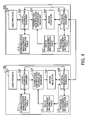
- Fig. 4 is a functional block diagram of the computers.
- the computer 100 is provided with a communication management information table 111, a route management information table 112, a physical management information table 113, a user process 121, a logical communication manager 122, a connection identification information manager 123, a device selector 124, and a physical communication manager 125.
- the communication management information table 111 manages information on logical communication routes (logical connections) which is provided to the user process 121.
- the route management information table 112 manages transmission routes (communication devices and transmission routes) to communication partners.
- the physical management information table 113 manages the states of connections (physical connections) which are established on physical transmission routes.
- the user process 121 executes processes based on the application programs. For communication with another computer, the user process 121 operates as a server or as a client.
- the user process 121 functioning as a client sends a communication start request in response to an input command requesting for a process including communication with a server.
- This communication start request includes partner connection identifier/own communication identifier/partner communication identifier.
- the logical communication manager 122 When the logical communication manager 122 receives the communication start request from the user process 121, it creates the communication management information table 111. The logical communication manager 122 recognizes a logical connection in a tree structure (communication management tree) based on the communication management information table 111. When the logical communication manager 122 creates the communication management information table 111, it updates the communication management tree. Then the contents of the communication start request are sent to the connection identification information manager 123.
- a tree structure communication management tree
- connection identification information manager 123 recognizes physical connections in a tree structure (state management tree) based on the route management information table 112 to determine whether identifiers are effective and which devices are usable. The connection identification information manager 123 gives the determination result to the device selector 124.
- the device selector 124 determines which device and route are to be used, based on a load status with the round robin method or the like. When the device selector 124 selects a route to be used, it sends a request for establishing communication, to the physical communication manager 125 being connected with the selected route.
- the physical communication manager 125 creates the route management information table 112 in response to the communication start request from the device selector 124 and tries to establish a connection. When the connection is failed, the device selector 124 continues this process to reselect a device to be used. Then the physical communication manager 125 retries a connection by using the reselected device.
- the computer 200 is provided with a communication management information table 211, a route management information table 212, a physical management information table 213, a user process 221, a logical communication manager 222, a connection identification information manager 223, a device selector 224, and a physical communication manager 225.
- the constituent elements function in the same way as those of the computer 100.
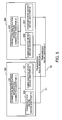
- Fig. 5 is a conceptual diagram of connections in this embodiment. As shown in Fig. 5, the computer 100 selects a communication device 106, 107 to be used for communication, based on connection identification information 131. Similarly, the computer 200 selects a communication device 206, 207 to be used for communication, based on connection identification information 231.
- connection identifiers of the computers 100 and 200 are taken as “1” and “2,” respectively.
- identifiers of the communication devices 106 and 107 of the computer 100 are taken as “A” and “B,” respectively.
- the identifiers of the communication devices 206 and 207 of the computer 200 are taken as "C” and "D,” respectively.
- the communication devices 106 and 206 are connected to each other via a transmission route 31 of which the identifier is taken as "X.”
- the communication devices 107 and 207 are connected to each other via a transmission route 32 of which the identifier is taken as "Y.”
- Fig. 6 shows an example of the data structure of the communication management information table.
- the communication management information table 111 is created for each logical connection and each communication management information table is given a communication identifier.
- the communication management information table 111 has columns for status of own process, logical communication management identifier, own connection identifier, partner connection identifier, physical communication, own communication identifier, partner communication identifier, reconnection availability, and establishment. Information arranged in a row is associated with each other.
- the status of own process column shows whether a user process of the own computer performing communication is a server or a client.
- the logical communication management identifier column shows identification information identifying a logical connection, which is recognized by the process.
- the own connection identifier column shows the identification information (for example, IP address) of the own computer on the network.
- the partner connection identifier column shows the identification information of a partner computer on the network.
- the physical communication column shows the identification information of a transmission route to be used for the communication.
- the own communication identifier column shows the identification information of the user process which performs the communication.
- the partner communication identifier column shows the identification information of the user process which is the communication partner.
- the reconnection availability column shows whether reconnection can be made or not. "Y" in this reconnection availability column indicates reconnectable.
- the establishment column shows whether a physical connection has been established. In this Fig. 6, "Y" in this establishment column indicates that a physical connection has been established.
- Fig. 7 shows an example of the data structure of the route management information table.
- the route management information table 112 has columns for route identifier, partner connection identifier, used device, route, number of using lines, and usability. Information arranged in a row is associated with each other.
- the route identifier column shows the identification information (combination of the identification information of a communication device and the identification information of a transmission route) of a communication route.
- the partner connection identifier column shows the connection identifier (for example, IP address) of a communication partner computer.
- the used device column shows the identification information of a communication device.
- the route column shows the identification information of the transmission route.
- the number of using lines column shows the number of lines (physical connections) which uses this communication route for communication.
- the usability column shows whether this communication route is usable. In this Fig. 7, usable is represented by "Y" while unusable is represented by "N.”
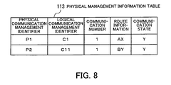
- Fig. 8 shows an example of the data structure of the physical management information table.
- the physical management information table 113 has columns for physical communication management identifier, logical communication management identifier, communication number, route information and communication state. Information arranged in a row is associated with each other.
- the physical communication management identifier column shows identification information specifying a physical connection.
- the logical communication management identifier column shows identification information specifying a logical connection to which this physical connection belongs.
- the communication number column shows the serial number of this physical communication in the same logical connection.
- the route information column shows the identification information of a transmission route to be used for the communication.
- the communication state column shows information showing a communication state. In this Fig. 8, communicable is represented by a communication state "Y" while incommunicable is represented by a communication state "N.”
- the state management tree and the communication management tree are created based on such structured data.
- Fig. 9 shows an example of the state management tree.
- the connection identifier "1" (own connection identifier) of the computer 100 is set as the root.
- the connection identifier "2" (partner connection identifier) of the communication partner computer 200 is set.
- the identifiers "A" and "B” of the used devices are set.
- Beneath the used devices the identifiers "X” and "Y” of the routes (transmission routes 31 and 32) connected to the used devices are set.
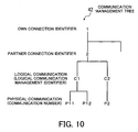
- Fig. 10 shows an example of the communication management tree.
- the connection identifier "1" (own connection identifier) of the computer 100 is set as the root.
- the connection identifier "2" (partner connection identifier) of the communication partner computer 200 is set.
- Beneath the partner connection identifier logical communication management identifiers "C1" and "C2" which are identification information on logical connections are set.
- Beneath the logical connections communication numbers "P11,” “P12,” and “P2" which are the physical communication identifiers are set.
- the following process is executed.
- the user process 121 sends a communication start request (including a partner connection identifier, an own communication identifier, and a partner communication identifier)
- the logical communication manager 122 creates the communication management information table 111. Since the communication management information table 111 for the communication start request is created, the communication management tree which is recognized by the logical communication manager 122 is updated. Then the communication start request is given to the connection identification information manager 123 to establish this connection.
- connection identification information manager 123 recognizes the state management tree from the route management information table 112. Then the connection identification information manager 123 determines whether there is a transmission route to a computer with the partner connection identifier and which communication device is used for communication via the transmission route. The connection identification information manager 123 sends the determination result to the device selector 124.
- the device selector 124 detects the load statuses (for example, the number of using lines) of the communication devices which are usable for communication with the computer specified by the partner connection identifier, and determines a communication device to be used, with the round robin method.
- the information on the communication device to be used is sent to the physical communication manager 125.
- the physical communication manager 125 creates the management information tables and tries to establish this connection. Specifically, when the physical communication manager 125 sends a connection request to the computer 200 and receives a reply of connection permission, it establishes the connection. When the connection is failed, the device selector 124 continues this process. The device selector 124 selects another communication device and notifies the physical communication manager 125 of this selection. The physical communication manager 125 retries to make a connection based on the given communication information. When this connection can be established successfully, the physical communication manager 125 updates the route management information table 212 and the physical management information table 213. Then the logical communication manager 122 is notified of this establishment of the physical connection and updates the communication management information table 111.
- the physical communication manager 225 receives the connection request from the physical communication manager 125 and notifies the logical communication manager 222 of this request. Then the logical communication manager 222, the connection identification information manager 223, and the device selector 224 operate to select a communication device to be used and update the communication management information table 211, the route management information table 212, and the physical management information table 213, in the same way as when the user process 211 outputs a connection start request. In a case where the connection request is met, the physical communication manager 225 sends a reply of connection permission. Then when an establishment declaration is given from the computer 100, the physical communication manager 225 establishes this physical connection. The logical communication manager 222 is notified of this establishment of the physical connection and updates the communication management information table 211.
- the physical communication manager 125 is able to establish some physical connections via different transmission routes for one logical connection. In this case, the physical communication manager 125 assigns each physical connection a communication number from 1. To establish a physical connection to be used instead of a troubled physical connection, the physical communication manager 125 sends a reconnection request via another transmission route by using the same communication number. When the new physical connection is established, communication can resume with the same communication number as before the trouble.
- each communicating computer is designed to be able to receive connection requests including the own communication identifier even after a connection is established.
- a process when a process operates as a server, it can receive connection requests from a client.
- a server function at least to receive connection requests
- the logical communication manager 122 While normal communication is performed after a connection is established, the logical communication manager 122 directly sends requests to the physical communication manager 125.
- the physical communication manager 125 gives data to the physical communication manager 225 of the computer 200.
- the physical communication manager 225 gives the received data to the logical communication manager 222.
- the logical communication manager 222 gives the data to the user process 221.
- one or both of the physical communication managers 125 and 225 detect the trouble.
- communication devices using the InfiniBand architecture can detect troubles in transmission routes and notify higher-ranked controllers (physical communication manager 125, 225).
- the physical communication manager 125 When the physical communication manager 125 detects a trouble, it requests the device selector 124 to reselect a communication device to be used. Then, the physical communication manager 125 reestablishes this communication via the communication device selected by the device selector 124. In this connection, the same communication number is used for the troubled physical connection and the new physical connection.
- the physical communication manager 225 receiving the connection request for reconnection gives this request to the logical communication manager 222.
- the logical communication manager 222 determines whether this request is a reconnection request, based on whether the same connection identifiers/communication identifiers/communication number exists in the communication management information table 211. The determination result is given to the connection identification information manager 223.
- the connection identification information manager 223 deletes the existing connection identification information on the physical connection from the physical management information table 213 and accepts the reconnection request.
- a first arriving reconnection request has priority. If reconnection requests are made at the same time (before reconnection is completed), a request from one of a client and a server (the function of a user process) has priority. In a case where reconnection requests from a server have priority, for example, the server computer discards reconnection requests from a client computer. Alternatively, a request from one (normally, client) which first sends a connection request may have priority.
- each established connection is assigned a communication number.
- a plurality of physical communication are considered as being under the logical connection, and simultaneous communication is performed by sharing loads with a division rule of the logical communication managers 122 and 222.
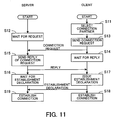
- Fig. 11 is a sequence diagram showing a procedure of establishing a connection.
- Fig. 11 shows the server process on the left side and the client process on the right side. A flow of normally establishing a connection will be described with the user process 121 of the computer 100 as a server and the user process 221 of the computer 200 as a client.
- the client computer 200 selects a connection partner in response to a communication start request from the user process 221 (step S11).
- the communication start request includes a partner connection identifier, an own communication identifier, and a partner communication identifier in order to specify the communication partner. It is now considered that the computer 100 is selected as the connection partner.
- the server computer 100 is in standby mode for receiving a connection request (step S12).
- the computer 200 sends a connection request to the computer 100 (step S13). Then the computer 200 enters standby mode for receiving a reply (step S14).
- the computer 100 When receiving the connection request, the computer 100 sends a reply of a connection request (step S15). Then the computer 100 enters standby mode for receiving an establishment declaration (step S16).
- the computer 200 receiving the reply of the connection request issues an establishment declaration (step S17). Thereby the computer 200 has an established connection (step S18).
- the computer 100 receiving the establishment declaration also has the established connection (step S19) .
- FIG. 12 and 13 show server information in the upper row and client information in the lower row.
- Fig. 12 shows the first half of the state transitions recognized by the information tables.
- the first state (ST1) is a state before connection establishment starts.
- the server communication management information table 111 shows status of own process "server,” logical communication management identifier "C1,” own connection identifier "1,” partner connection identifier "-,” physical communication “--,” own communication identifier “10,” partner communication identifier "--,” reconnection availability "-,” and establishment “N.”
- “-” represents that no information is registered.
- the establishment "N” represents that a connection has not been established.
- the client communication management information table 211 shows status of own process "client,” logical communication management identifier "C2,” own connection identifier “2,” partner connection identifier "1,” physical communication “--,” own communication identifier “99,” partner communication identifier “10,” reconnection availability “Y,” and establishment “N.”
- “-” represents that no information is registered.
- the establishment “N” represents that a connection has not been established.
- the partner identifier and the partner communication identifier specified by a communication start request are registered. At this time, no information is registered in the physical management information tables 113 and 213.
- the second state (ST2) is a state after the client selects a connection partner (step S11).
- the client computer 200 selects the connection partner, physical communication "P2" is set in the client communication management information table 211.
- the third state (ST3) is a state after the server sends a reply of a connection request (step S15).
- partner connection identifier "2,” partner communication identifier "99,” and reconnection availability "Y" are set in the server communication management information table 111.
- Fig. 13 shows the second half of the state transitions recognized by the information tables.
- the fourth state (ST4) is a state after the client issues an establishment declaration (step S17).
- establishment "Y" is set in the client communication management information table 211.
- the establishment "Y” is a flag indicating that a connection has been established.
- the communication state column in the client physical management information table 213 is changed to "Y" (indicating a communicable state).
- the fifth state (ST5) is a state after a connection is established (step S19).
- establishment "Y" is set in the communication management information table 111.
- the communication state column of the server physical management information table 113 is changed to "Y.”
- a physical connection is established and information on the logical connection and physical connection are registered in the communication management information tables and the physical management information tables of the server and client.
- Fig. 14 is a flowchart showing a server's connection establishment process. This process of Fig. 14 will be described following step numbers.
- Step 21 The server computer 100 determines whether a connection request has arrived. When yes, this process goes on to step S22. When no, this step S21 is repeated until a connection request arrives.
- Step S22 The computer 100 determines whether the received connection request is from a connectable computer. When yes, this process goes on to step S23. When no, the process goes on to step S29.
- Step S23 The computer 100 stores information indicating whether the connection partner allows reconnection. This information on whether reconnection is allowed is detected from, for example, a connection request. For this process, the client computer 200 sends a connection request together with the information indicating whether to allow reconnection.
- Step S24 The computer 100 sends a reply of connection permission to the client computer 200.
- Step S25 The computer 100 determines whether a prescribed time has passed after the replay was sent in step S24. When yes, this process goes on to step S29. When no, the process goes on to step S26.
- Step S26 The computer 100 determines whether a reply has arrived from the client computer 200. When yes, this process goes on to step S27. When no, the process returns back to step S25 to determine whether a prescribed time has passed.
- Step S27 The computer 100 determines whether the received reply is an establishment declaration. When yes, this process goes on to step S28. When no (for example, a notification of connection rejection), the process goes on to step S30.
- Step S28 The computer 100 establishes this connection and ends this process.
- Step S29 Since the connection request is from an unconnectable computer or since the computer 100 does not receive a reply from the client computer 200 for a prescribed time after sending the reply of connection permission, the computer 100 sends a reply of connection rejection to the computer 200.
- Step S30 Since the computer 100 sent the reply of connection rejection or since the computer 100 received a reply other than an establishment declaration in step S27, it decides a connection failure and ends this process.
- Fig. 15 is a flowchart showing a client's connection establishment process. This process of Fig. 14 will be described following step numbers.
- Step S41 The client computer 200 selects a connection partner.
- Step S42 The computer 200 sends a connection request to the connection partner computer 100.
- Step S43 The computer 200 determines whether a prescribed time has passed after sending the connection request. When yes, this process goes on to step S51. When no, the process goes on to step S44.
- Step S44 The computer 200 determines whether a reply has come from the server computer 100. When yes, this process goes on to step S45. When no, the process returns back to step S43.
- Step S45 The computer 200 determines whether the received reply indicates connection permission. When yes, this process goes on to step S46. When no, the process goes on to step S52.
- Step S46 The computer 200 determines whether this connection can be established. When yes, this process goes on to step S47. When no, the process goes on to step S51.
- Step S47 The computer 200 determines whether the partner computer 100 allows reconnection. When yes, this process goes on to step S48. When no, the process goes on to step S49.
- Step S48 The computer 200 sets a server with the own communication identifier.
- Step S49 The computer 200 sends a reply of establishment declaration to the computer 100.
- Step S50 The computer 200 establishes this connection and ends this process.
- Step S51 Since the computer 200 does not receive a reply for a prescribed time after sending the connection request or since the computer 200 determined in step S46 that this connection could not be established, it sends a reply of connection rejection to the computer 100.
- Step S52 Since the computer 200 sent the reply of connection rejection or since the computer 200 received the reply of connection rejection in step S45, it decides a connection failure and ends this process.
- Fig. 16 is a sequence diagram showing a procedure for a case where a client computer detects a connection trouble.
- Fig. 16 shows a server process on the left side and a client process on the right side. A flow of normally reestablishing a connection will be described with the user process 121 of the computer 100 as a server and the user process 221 of the computer 200 as a client.
- the client computer 200 detects a trouble in a physical connection and selects a reconnection route (step S61). Thereby the computer 100 is selected as a reconnection partner. At this time, the server computer 100 is in standby mode for receiving a reconnection request (step S62).
- the computer 200 sends a reconnection request to the computer 100 (step S63). Then the computer 200 enters standby mode for receiving a reply (step S64).
- the computer 100 receiving the reconnection request sends a reply to the reconnection request (step S65). Then the computer 100 enters standby mode for receiving an establishment declaration (step S66).
- the computer 200 receiving the reply to the reconnection request issues an establishment declaration (step S67). Thereby the computer 200 has an established connection (step S68). The computer 100 receiving the establishment declaration also has the established connection (step S69).
- a connection is reestablished.
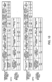
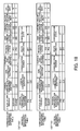
- the state transitions recognized by the communication management information tables and the physical management information tables in a case where the client detects a trouble and sends a reconnection request will be now described with reference to Figs. 17 and 18.
- the communication management information tables and the physical management information tables of Figs. 17 and 18 show server information in the upper row and client information in the lower row.
- Fig. 17 shows the first half of the state transitions recognized by the information tables.
- the first state (ST11) is a state after the client detects a trouble.
- registered in the server communication management information table 111 are status of own process "server,” logical communication management identifier "C1,” own connection identifier “1,” partner connection identifier “2,” physical communication “P1,” own communication identifier “10,” partner communication identifier "99,” reconnection availability “Y,” and establishment “Y.”
- client communication management information table 211 registered in the client communication management information table 211 are status of own process "client,” logical communication management identifier "C2,” own connection identifier “2,” partner connection identifier "1,” physical communication “--,” own communication identifier “99,” partner communication identifier "10,” reconnection availability "Y,” and establishment "N.”
- the partner identifier and the partner communication identifier specified by a communication start request are registered in the client communication management information table 211.
- registered in the server physical management information table 113 are physical communication management identifier "P1,” logical communication management identifier "C1,” communication number "1,” route information "AX,” and communication state "Y.”
- no information is registered in the client physical management information table 213.
- the second state (ST12) is a state after the client selects a reconnection route (step S61) and sends a reconnection request (step S63).
- step S61 selects a reconnection route
- step S63 sends a reconnection request
- step S63 sends a reconnection request
- physical communication "P4" is set in the client communication management information table 211.
- the third state (ST13) is a state after the server sends a reply to the reconnection request (step S65) .
- the server computer 100 recognizes the trouble because of the reception of the reconnection request, so that the establishment column of the communication management information table 111 is changed to "N.” At this time, the communication state column of the server physical management information table 113 is changed to "N.”
- Fig. 18 shows the second half of the state transitions recognized by the information tables.
- the fourth state (ST14) is a state after the client issues an establishment declaration (step S67).
- the establishment column of the client communication management information table 211 is changed to "Y.”
- the communication state column of the client physical management information table 213 is changed to "Y.”
- the fifth state (ST15) is a state after a connection is established (step S69).
- the server computer 100 receives the establishment declaration, the establishment column of the physical management information table 111 is changed to "Y.”
- the communication state column of the server physical management information table 113 is changed to "Y.”
- reconnection is automatically made by using a transmission route different from a troubled transmission route, in response to a reconnection request from a client.
- Fig. 19 is a sequence diagram showing a procedure for a case where a server computer detects a connection trouble.
- Fig. 19 shows a server process on the left side and a client process on the right side. A flow of normally reestablishing a connection will be described with the user process 121 of the computer 100 as a server and the user process 221 of the computer 200 as a client.
- the server computer 100 detects a trouble in a physical connection and selects a reconnection route (step S71). Thereby the computer 200 is selected as a reconnection partner. At this time, the client computer 200 is in standby mode for receiving a reconnection request (step S72).
- the computer 100 sends a reconnection request to the computer 200 (step S73). Then the computer 100 enters standby mode for receiving a reply (step S74).
- the computer 200 receiving the reconnection request sends a reply to the reconnection request (step S75). Then the computer 200 enters standby mode for receiving an establishment declaration (step S76).
- the computer 100 receiving the reply to the reconnection request issues an establishment declaration (step S77). Thereby the computer 100 has an established connection (step S78). In addition, the computer 200 receiving the establishment declaration also has the established connection (step S79).
- a connection is reestablished.
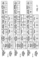
- the state transitions recognized by the communication management information tables and the physical management information tables in a case where the server detects a trouble and sends a reconnection request will be described with reference to Figs. 20 and 21.
- the communication management information tables and the physical management information tables of Figs. 20 and 21 show server information in the upper row and client information in the lower row.
- Fig. 20 is the first half of the state transitions recognized by the information tables.
- the first state (ST21) is a state after the server detects a trouble.
- registered in the server communication management information table 111 are status of own process "server,” logical communication management identifier "C1,” own connection identifier "1,” partner connection identifier "2,” physical communication "--,” own communication identifier “10,” partner communication identifier "99,” reconnection availability "Y,” and establishment "N.”
- client communication management information table 211 registered in the client communication management information table 211 are status of own process "client,” logical communication management identifier "C2,” own connection identifier “2,” partner connection identifier "1,” physical communication “P2,” own communication identifier “99,” partner communication identifier "10,” reconnection availability “Y,” and establishment “Y.”
- the second state (ST22) is a state after the server selects a reconnection route (step S71) and sends a reconnection request (step S73).
- step S71 selects a reconnection route
- step S73 sends a reconnection request
- the third state (ST23) is a state after the client sends a reply to the reconnection request (step S75).
- the client computer 200 recognizes the trouble because of the reception of the reconnection request, the establishment column of the communication management information table 211 is changed to "N.”
- the communication state column of the client physical management information table 213 is changed to "N.”
- Fig. 21 is the second half of the state transitions recognized by the information tables.
- the fourth state (ST24) is a state after the server issues an establishment declaration (step S77).
- the server computer 100 issues the establishment declaration
- the establishment column of the server communication management information table 111 is changed to "Y.”
- the communication state of the server physical management information table 113 is changed to "Y.”
- the fifth state (ST25) is a state after the connection is established (step S79).
- the client computer 200 receives the establishment declaration, the establishment column of the communication management information table 211 is changed to "Y.”
- the communication state column of the client physical management information table 213 is changed to "Y.”
- reconnection is automatically made via a transmission route different from a troubled transmission route, in response to a reconnection request from the server.
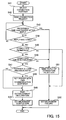
- Fig. 22 is a flowchart showing how a server computer operates when detecting a connection trouble. This process of Fig. 22 will be described following step numbers.
- Step S81 The server computer 100 which detected a trouble in a physical connection determines whether reconnection to the client computer 200 can be made. When yes, this process goes on to step S82. When no, the process goes on to step S89.
- Step S82 The computer 100 selects a reconnection route.
- Step S83 The computer 100 sends a reconnection request by using the same communication identifier which was used for the troubled physical connection.
- Step S84 The computer 100 determines whether a reconnection request has arrived from the partner (client computer 200). When yes, this process goes on to step S85. When no, the process goes on to step S86.
- Step S85 The computer 100 rejects the reconnection request sent from the client computer 200.
- Step S86 The computer 100 determines whether a reply to the reconnection request has come. When yes, this process goes on to step S87. When no, the process returns back to step S84.
- Step S87 The computer 100 determines whether the reply to the reconnection request is a notification of reconnection rejection. When yes, this process goes on to step S89. When no, the process goes on to step S88.
- Step S88 The computer 100 reestablishes a connection (physical connection) by using the communication route selected in step S82 and ends this process.
- Step S89 The computer 100 decides to disconnect the connection and ends this process.
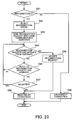
- Fig. 23 is a flowchart showing how a client computer operates when detecting a connection trouble. This process of Fig. 23 will be described following step numbers.
- Step S91 The client computer 200 which detected a trouble in a physical connection determines whether a connection to the server computer 100 can be made. When yes, this process goes on to step S92. When no, the process goes on to step S99.
- Step S92 The computer 200 selects a reconnection route.
- Step S93 The computer 200 sends a reconnection request by using the same communication identifier which was used for the troubled physical connection.
- Step S94 The computer 200 determines whether a reconnection request has arrived from the partner (server computer 100). When yes, this process goes on to step S95. When no, the process goes on to step S96.
- Step S95 The computer 200 accepts the reconnection request sent from the server computer 100. Then this process goes on to step S98.
- Step S96 The computer 100 determines whether a reply to the reconnection request has come. When yes, this process goes on to step S97. When no, the process returns back to step S94.
- Step S97 The computer 100 determines whether the reply to the reconnection request is a notification of reconnection rejection. When yes, this process returns back to step S94. When no, the process goes on to step S98.
- Step S98 The computer 100 reestablishes a connection (physical connection) via the communication route selected in step S92 and ends this process.
- Step S99 The computer 100 decides to disconnect the connection and ends this process.
- a connection route being used by few lines is selected based on the route management information table. For example, referring to the route management information table 112 of Fig. 7, a route with a route identifier "AX" is selected.
- Fig. 24 is a flowchart showing how to select a connection route. A case where the computer 100 selects a connection route will be described. This process of Fig. 24 will be described following step numbers.
- Step S101 The computer 100 selects a route being used by the fewest lines, out of usable routes. In this connection, some routes may be selected.
- Step S102 The computer 100 determines whether one route has been selected. When one route has been selected, this process goes on to step S104. When some routes have been selected, the process goes on to step S103.
- Step S103 The computer 100 selects a route having the smallest route identifier (the first order in view of letter arrangement). For example, when route identifiers are indicated in alphabets, A is the smallest while Z is the largest.
- Step S104 The computer 100 determines one selected route as a connection route.
- the above example is a case where one physical connection is established between computers. Alternatively, some physical connections may be established for one logical connection. In this case of establishing a plurality of physical connections via different routes, a plurality of physical communication management identifiers are registered in the physical communication column of a communication management information table.
- Fig. 25 shows an example of the server communication management information table for a case where communication is performed via a plurality of routes.
- the communication management information table 111 of Fig. 25 shows that two physical connections with physical communication management identifiers "P1" and "P2" are established for a logical connection with a logical communication management identifier "C1.”
- Fig. 26 shows an example of the client communication management information table for a case where communication is performed via a plurality of routes.
- the communication management information table 211 of Fig. 26 shows that two physical connections with physical communication management identifiers "P3" and "P4" are established for a logical connection with a logical communication management identifier "C2.”
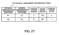
- Fig. 27 shows an example of the server physical management information table for a case where communication is performed via a plurality of routes.
- the physical management information table 113 of Fig. 27 shows that physical management information on two physical connections with the same logical communication management identifier "C1" is registered. These connections are different in connection route.
- Fig. 28 shows an example of the client physical management information table for a case where communication is performed via a plurality of routes.
- the physical management information table 213 of Fig. 28 shows that physical management information on two physical connections with the same logical communication management identifier "C2" is registered. These connections are different in connection route.
- a negotiation packet for performing division is first sent.
- the negotiation packet is sent from a sending end with a physical connection with the smallest communication number and requires a reply. Only a case where data is to be transferred via a plurality of routes requires a reply.
- a request packet is sent from a sending end to a receiving end.
- the request packet includes information on transfer size and division size.
- the transfer size is the size of all data to be transferred.
- the division size is the maximum size of data which is transmittable via one physical connection.
- the receiving end receiving the request packet sends a reply packet to the sending end.
- the reply packet includes information on reception size.
- the reception size is the size of data which is receivable on the receiving end.
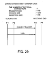
- Fig. 29 shows an example of data transfer for a case where division is unnecessary. This example is made with two physical connections, transfer size of 1KB, division size of 1MB, and reception size of 1KB.
- the division size is larger than the transfer size, data is transferred from the sending end to the receiving end after a request packet. Since transfer size ⁇ division size, data is not divided even if two physical connections are established but the data is transferred via one physical connection ("P1" of the sending end and "P3" of the receiving end).
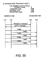
- Fig. 30 shows the first example for the data division and transfer. This example is made with two physical connections, transfer size of 8MB, division size of 1MB, and reception size of 8MB. In this case where the transfer size is larger than the division size, data is divided and transferred with the two physical connections. In this case, the sending end sends a request packet and the receiving end sends a reply packet.
- the sending end recognizes that the receiving end is able to receive data of the transfer size, based on the reception size indicated by the reply packet, and starts the data division and transfer.
- 1MB data transfer from the sending end "P1" to the receiving end "P3” and 1MB data transfer from the sending end "P2" to the receiving end "P4" are alternately performed. Then 8MB data transfer is completed in the 8th transfer.
- Fig. 31 shows the second example for the data division and transfer. This example is made with two physical connections, transfer size of 7MB, division size of 2MB, and reception size of 7MB. In this case where there is a reminder when the transfer size is divided by the division size, only the remaining data is transferred in the last data transfer.
- 2MB data transfer from the sending end "P1" to the receiving end "P3" and 2MB data transfer from the sending end "P2" to the receiving end "P4" are alternately performed. Then after 2MB data transfer is performed three times, the remaining 1MB data is transferred in the fourth data transfer.
- Fig. 32 shows the third example for the data division and transfer. This example is made with two physical connections, transfer size of 8MB, division size of 2MB, and reception size of 5MB. In this case where the transfer size is larger than the reception size, only data of the reception size is transferred.
- 2MB data transfer from the sending end "P1" to the receiving end "P3" and 2MB data transfer from the sending end "P2" to the receiving end "P4" are alternately performed. Then after the 2MB data transfer is performed twice, the remaining 1 MB data is transferred in the third data transfer. That is, 5MB data in total is transferred.
- Fig. 33 is a sequence diagram showing the data division and transfer process. This process of Fig. 33 will be described following step numbers. A case where data is transferred from the computer 100 to the computer 200 will be described.
- Step S111 The receiving computer 200 is in standby mode for receiving a request packet.
- Step S112 The sending computer 100 sends a request packet to the receiving computer 200 in response to a request from the user process.
- Step S113 The computer 200 receiving the request packet compares the transfer size to the division size, the sizes specified by the request packet. When the transfer size is larger than the division size, this process goes on to step S114. When the division size is larger, the process goes on to step S118.
- Step S115 Similarly to the receiving computer 200, the computer 100 sending the request packet also compares the transfer size to the division size. When the transfer size is larger than the division size, this process goes on to step S116. When the division size is larger, the process goes on to S117.
- Step S117 The computer 100 enters standby mode for receiving a reply packet from the computer 200.
- Step S118 The computer 200 sends a reply packet including reception size information to the computer 100.
- Step S119 The computer 100 receiving the reply packet equalizes the transfer size to the reception size.
- Step S120 The computer 100 calculates LOOP and AN values by taking PN as the number of physical connections, PS as division size and TS as transfer size (equal to reception size).
- LOOP is the quotient of TS ⁇ (PS ⁇ PN), and its reminder is taken as LS.
- AN is the quotient of LS-PS, and its reminder is taken as AS.
- Step S121 The computer 200 calculates LOOP and AN values by taking PN as the number of physical connections, PS as division size, and TS as reception size.
- LOOP is the quotient of TS ⁇ (PS ⁇ PN) , and its reminder is taken as LS.
- AN is the quotient of LS ⁇ PS, and its reminder is taken as AS.
- Step S122 The computer 100 transfers data of division size via each established physical connection, for a number of times specified by LOOP.
- Step S123 The computer 200 receives data of division size via each established physical connection, for a number of times specified by LOOP.
- Step S124 The computer 100 transfers data of division size via each of physical connections with AN and lower communication numbers.
- Step S125 The computer 200 receives data of division size via each of physical connections with AN and lower communication numbers.
- Step S126 The computer 100 transfers data of AS via a physical connection with an AN or lower communication number.
- Step S127 The computer 200 receives data of AS via a physical connection with an AN or lower communication number.
- Suitable computer-readable storage media include magnetic storage media, optical discs, magneto-optical storage media, and semiconductor memory devices.
- Magnetic storage media include hard disk drives (HDD), flexible disks (FD), and magnetic tapes.
- Optical discs include DVDs (Digital Versatile Disc), DVD-RAMs (Random Access Memory), CD-ROMs (Compact Disc Read Only Memory), and CD-R (Recordable)/RW (ReWritable).
- Magneto-optical storage media include MOs (Magneto-Optical disc).
- Each computer stores the program in its local storage unit, which has previously been installed from a portable storage medium or downloaded from a server computer.
- the computer performs intended functions by running the program read out of the local storage unit.
- the computer may execute the program, reading out program files directly from a portable storage medium.
- Another alternative method is that the computer dynamically downloads and runs the program from a server computer to execute the functions.
- one or more physical connections are defined as a logical connection, and when a trouble happens in a physical connection, reconnection is made via a different communication device, and communication is performed via the physical connections included in the logical connection in response to a communication request applied to the logical connection. Therefore, a process which sends the communication request recognizes that the logical connection is continuously kept alive. As a result, a retry process which is performed when a communication trouble happens is not required, resulting in continuing the communication and realizing high reliable communication between computers.
Landscapes
- Engineering & Computer Science (AREA)
- Computer Networks & Wireless Communication (AREA)
- Signal Processing (AREA)
- Computer Security & Cryptography (AREA)
- Environmental & Geological Engineering (AREA)
- Computer And Data Communications (AREA)
- Data Exchanges In Wide-Area Networks (AREA)
Applications Claiming Priority (1)
| Application Number | Priority Date | Filing Date | Title |
|---|---|---|---|
| PCT/JP2003/002277 WO2004077781A1 (ja) | 2003-02-27 | 2003-02-27 | 通信制御プログラムおよび通信制御方法 |
Publications (2)
| Publication Number | Publication Date |
|---|---|
| EP1599004A1 true EP1599004A1 (de) | 2005-11-23 |
| EP1599004A4 EP1599004A4 (de) | 2010-04-28 |
Family
ID=32923112
Family Applications (1)
| Application Number | Title | Priority Date | Filing Date |
|---|---|---|---|
| EP03707157A Withdrawn EP1599004A4 (de) | 2003-02-27 | 2003-02-27 | Kommunikationssteuerprogramm und kommunikationssteuerverfahren |
Country Status (4)
| Country | Link |
|---|---|
| US (1) | US7768905B2 (de) |
| EP (1) | EP1599004A4 (de) |
| JP (1) | JP4040628B2 (de) |
| WO (1) | WO2004077781A1 (de) |
Families Citing this family (8)
| Publication number | Priority date | Publication date | Assignee | Title |
|---|---|---|---|---|
| US7904563B2 (en) * | 2006-03-31 | 2011-03-08 | Microsoft Corporation | Establishing and utilizing terminal server dynamic virtual channels |
| JP4499757B2 (ja) * | 2007-03-27 | 2010-07-07 | 株式会社エヌ・ティ・ティ・ドコモ | 通信接続サーバ及び通信接続方法 |
| US7911830B2 (en) * | 2007-05-17 | 2011-03-22 | Integrated Magnetoelectronics | Scalable nonvolatile memory |
| KR101010911B1 (ko) * | 2008-12-31 | 2011-01-26 | 엔에이치엔(주) | 메시징 네트워크 시스템의 메시지 송수신 방법 |
| US8429674B2 (en) * | 2010-07-20 | 2013-04-23 | Apple Inc. | Maintaining data states upon forced exit |
| CN103092701B (zh) | 2011-10-31 | 2017-02-08 | 联想(北京)有限公司 | 一种通信方法、装置及电子设备 |
| JP2014022835A (ja) * | 2012-07-13 | 2014-02-03 | Fujitsu Ltd | 電子装置および送信制御方法 |
| US9172600B1 (en) * | 2013-12-31 | 2015-10-27 | Symantec Corporation | Efficient I/O error analysis and proactive I/O failover to alternate paths for InfiniBand channel |
Family Cites Families (27)
| Publication number | Priority date | Publication date | Assignee | Title |
|---|---|---|---|---|
| US5182751A (en) * | 1990-12-31 | 1993-01-26 | At&T Bell Laboratories | Switching system using identical switching nodes |
| US5862335A (en) * | 1993-04-01 | 1999-01-19 | Intel Corp. | Method and apparatus for monitoring file transfers and logical connections in a computer network |
| DE4416719C2 (de) * | 1994-05-11 | 1998-08-20 | Siemens Ag | Schaltungsanordnung zum störungsfreien Umleiten eines Nachrichtenzellenstromes auf einen Ersatzweg |
| US6069894A (en) * | 1995-06-12 | 2000-05-30 | Telefonaktiebolaget Lm Ericsson | Enhancement of network operation and performance |
| US6246665B1 (en) * | 1995-12-27 | 2001-06-12 | Fujitsu Limited | Method for attending occurrence of failure in an exchange system that exchanges cells having fixed-length, and interface unit and concentrator equipped in the exchange system using the method |
| JPH09270793A (ja) * | 1996-04-03 | 1997-10-14 | Sony Corp | 通信制御方法 |
| JPH09326810A (ja) | 1996-06-06 | 1997-12-16 | Nippon Denki Ido Tsushin Kk | 障害時のコネクション切り替え方法 |
| US5841780A (en) * | 1996-08-29 | 1998-11-24 | Lucent Technologies Inc. | ISDN BRI link restoration without loss of calls |
| US5828652A (en) | 1996-09-30 | 1998-10-27 | Lucent Technologies, Inc. | Establishment of a flexible rate interface link to restore channels from a failed communication link |
| JPH10320327A (ja) | 1997-03-19 | 1998-12-04 | Fujitsu Ltd | 二重化された通信アダプタの切替方法、切替方式、および切替用プログラムを格納した記録媒体 |
| US6314525B1 (en) * | 1997-05-13 | 2001-11-06 | 3Com Corporation | Means for allowing two or more network interface controller cards to appear as one card to an operating system |
| US6308281B1 (en) * | 1998-09-02 | 2001-10-23 | International Business Machines Corporation | Virtual client to gateway connection over multiple physical connections |
| US6308282B1 (en) | 1998-11-10 | 2001-10-23 | Honeywell International Inc. | Apparatus and methods for providing fault tolerance of networks and network interface cards |
| US6473396B1 (en) * | 1999-01-04 | 2002-10-29 | Cisco Technology, Inc. | Use of logical addresses to implement module redundancy |
| US6301254B1 (en) * | 1999-03-15 | 2001-10-09 | Tellabs Operations, Inc. | Virtual path ring protection method and apparatus |
| US6763479B1 (en) * | 2000-06-02 | 2004-07-13 | Sun Microsystems, Inc. | High availability networking with alternate pathing failover |
| JP2002026909A (ja) * | 2000-07-11 | 2002-01-25 | Hitachi Ltd | 回線多重化方法及び情報中継装置 |
| EP1182903A1 (de) * | 2000-08-21 | 2002-02-27 | Lucent Technologies Inc. | Punkt-zu-Punkt Schutz in Punkt-zu-Mehrpunkt Netzwerken |
| US7046619B2 (en) * | 2000-11-07 | 2006-05-16 | Ciena Corporation | Method and system for bi-directional path switched network |
| GB2371706B (en) * | 2001-01-30 | 2003-04-23 | 3Com Corp | Link aggregation control for network devices |
| JP4141106B2 (ja) * | 2001-02-06 | 2008-08-27 | 富士通株式会社 | 帯域制御装置 |
| US6956824B2 (en) * | 2001-06-14 | 2005-10-18 | Tropic Networks Inc. | Extension of link aggregation protocols over the network |
| CA2459027C (en) * | 2001-06-15 | 2006-04-25 | Tropic Networks Inc. | Extension of link aggregation protocols over the network and a switching node therefor |
| ATE418198T1 (de) * | 2001-09-04 | 2009-01-15 | Rumi Sheryar Gonda | Verfahren zum unterstützen von sdh/sonet-aps auf ethernet |
| US20030063723A1 (en) * | 2001-09-28 | 2003-04-03 | Derek Booth | Interactive system for managing and remotely connecting customer utility loads |
| US7134040B2 (en) * | 2002-04-17 | 2006-11-07 | International Business Machines Corporation | Method, system, and program for selecting a path to a device to use when sending data requests to the device |
| US7145865B1 (en) * | 2002-06-26 | 2006-12-05 | Bellsouth Intellectual Property Corp. | Method for moving network elements with minimal network outages in an active ATM network |
-
2003
- 2003-02-27 JP JP2004568758A patent/JP4040628B2/ja not_active Expired - Fee Related
- 2003-02-27 WO PCT/JP2003/002277 patent/WO2004077781A1/ja not_active Ceased
- 2003-02-27 EP EP03707157A patent/EP1599004A4/de not_active Withdrawn
-
2005
- 2005-03-23 US US11/087,273 patent/US7768905B2/en not_active Expired - Fee Related
Also Published As
| Publication number | Publication date |
|---|---|
| JP4040628B2 (ja) | 2008-01-30 |
| EP1599004A4 (de) | 2010-04-28 |
| US20050180432A1 (en) | 2005-08-18 |
| US7768905B2 (en) | 2010-08-03 |
| WO2004077781A1 (ja) | 2004-09-10 |
| JPWO2004077781A1 (ja) | 2006-06-08 |
Similar Documents
| Publication | Publication Date | Title |
|---|---|---|
| US9071632B2 (en) | Service management roles of processor nodes in distributed node service management | |
| US6055568A (en) | Method and apparatus for dynamically configuring a decentralized network of computers | |
| JP4748086B2 (ja) | 通信中継装置、リソース解放方法および通信中継装置のプログラム | |
| KR20050012130A (ko) | 클러스터형 컴퓨터 시스템의 클러스터 데이터 포트 서비스 | |
| US7769839B2 (en) | Method and structure for autoconfiguration of overlay networks by automatic selection of a network designated router | |
| EP1599004A1 (de) | Kommunikationssteuerprogramm und kommunikationssteuerverfahren | |
| CN112788089A (zh) | 多边缘云的网络通讯控制方法及边缘运算装置与系统 | |
| WO2025139833A1 (zh) | 端口故障切换的方法、设备和存储介质 | |
| JP4948054B2 (ja) | 管理装置及び通信端末装置及び通信システム及び通信管理方法 | |
| KR100881538B1 (ko) | 블루투스 논리적 링크 제어 및 적응 프로토콜 채널을구성하는 방법 | |
| CN111669280B (zh) | 一种报文传输方法、装置及存储介质 | |
| US7656790B2 (en) | Handling link failures with re-tagging | |
| CN101237696B (zh) | 基站接入单元切换方法及基站 | |
| JPH1168884A (ja) | 伝送媒体接続装置および制御装置ならびに被制御装置および記憶媒体 | |
| EP1547321B1 (de) | Verfahren zur bestimmung eines übergeordneten portals in einem drahtlosen netzwerk und entsprechende portaleinrichtung | |
| JP2016181819A (ja) | ネットワークの制御装置及び制御方法、並びに、ネットワークスイッチ | |
| KR100445425B1 (ko) | 분산 레이드 제어기 환경에서의 부하 분산 방법 | |
| JP4579850B2 (ja) | ブレード型システムおよびコネクション管理方法 | |
| JP5114300B2 (ja) | ネットワークシステム、ネットワーク端末装置、及びlanスイッチ | |
| JP2007141129A (ja) | システム切替方法、その計算機システム及びプログラム | |
| KR19990053166A (ko) | 멀티포인트 통신 시스템 및 멀티캐스트 경로 오류 제어 및경로 재배정 방법 | |
| US11012369B2 (en) | Aggregated switch path optimization system | |
| JP2004007078A (ja) | 無線通信システム及び無線管理装置並びに収容装置選定方法及びプログラム | |
| WO2006057349A1 (ja) | 管理システム及びそれに用いられる装置と、そのプログラムと、管理方法 | |
| CN101415241A (zh) | 媒体资源管理的方法、系统和设备 |
Legal Events
| Date | Code | Title | Description |
|---|---|---|---|
| PUAI | Public reference made under article 153(3) epc to a published international application that has entered the european phase |
Free format text: ORIGINAL CODE: 0009012 |
|
| 17P | Request for examination filed |
Effective date: 20050317 |
|
| AK | Designated contracting states |
Kind code of ref document: A1 Designated state(s): AT BE BG CH CY CZ DE DK EE ES FI FR GB GR HU IE IT LI LU MC NL PT SE SI SK TR |
|
| RBV | Designated contracting states (corrected) |
Designated state(s): DE |
|
| A4 | Supplementary search report drawn up and despatched |
Effective date: 20100331 |
|
| 17Q | First examination report despatched |
Effective date: 20111212 |
|
| STAA | Information on the status of an ep patent application or granted ep patent |
Free format text: STATUS: THE APPLICATION IS DEEMED TO BE WITHDRAWN |
|
| 18D | Application deemed to be withdrawn |
Effective date: 20170809 |